

Page 1

GB Operating instructions for RolloSystems T2
VBD 509-1-GB (09.09)
Article No.: RS-T2-80
Page 2
2
GB
i
...describe how to connect and operate the RolloSystems T2
..
..
.
Before you begin work, please read these instructions through completely and follow all the
safety instructions.
Please store these instructions in a safe place and pass them on to any future owners.
Damage resulting from non-compliance with these instructions and safety instructions will void
the guarantee. We assume no liability for any consequential damage.
Dear Customers, ...
... With your purchase of this drive for sliding doors and sliding shutters you have chosen
a quality product manufactured by Rademacher. We would like to thank you for your confidence.
The RolloSystems T2
has been developed with the greatest possible convenience in mind.
Having applied uncompromising quality standards, and carried out thorough testing, we are proud
to be able to present you with this innovative product.
It’s brought to you by all the highly-qualified personnel
here at RADEMACHER.
These instructions...
i
Key to symbolsi
Danger of fatal electric shock
This sign warns of danger when working on electrical connections, components, etc. It requires
that safety precautions be taken to protect the life and health of the person concerned.
This concerns your safety.
Please pay particular attention and carefully follow all instructions marked with this symbol.
NOTE/IMPORTANT/CAUTION
This is to draw your attention to information that is important for trouble-free operation.
Page 3

3
GB
i
Introduction ...................................................................................................................2
Key to symbols .............................................................................................................. 2
General view ................................................................................................................. 4
Included in delivery ........................................................................................................ 5
Correct usage ................................................................................................................ 6
Permissible sliding doors / sliding shutters ........................................................................ 6
Operating conditions ....................................................................................................... 6
Incorrect usage .............................................................................................................. 7
General safety instructions ............................................................................................... 8
Functional description .............................................................................. 9
- Obstacle detection ................................................................................................. 10
- Manual decoupling ................................................................................................ 10
Overview of features ........................................................................... 11
Important information prior to assembly and installation .................................................... 12
Electrical connection / Power supply ............................................................................... 13
+ 12 V
output .................................................................................................... 13
Brief description of control inputs .................................................................................... 14
Connecting an external sensor or motion detector ............................................................. 15
Connecting a roller shutter switch ................................................................................... 16
Connecting the ArtMotion motion detector ....................................................................... 17
Drive menu structure ............................................................................ 19
Calling up functions / Setting assistance / Operation........................................................ 19
Calling up the menu and selecting a function (Example) .................................................... 20
Installation sequence............................................................................. 21
Automatic end point search / Brief explanation ................................................................ 22
Starting automatic end point search ................................................................................ 23
Reversing the running direction ...................................................................................... 24
Setting the braking distance .......................................................................................... 25
Setting the sensitivity of obstacle detection ...................................................................... 26
Setting speeds, automatically and manually ..................................................................... 27
1. Automatic setting of the speed according to the type of mounting .............................. 28
2. Switching to manual setting of opening speed ........................................................ 28
3. Switching to automatic speed setting according to the type of mounting ..................... 29
Setting the closing speed .............................................................................................. 30
Activating automatic closing ........................................................................................... 31
Switching acoustic signal on/off .................................................................................... 32
Switching Push mode on/off ......................................................................................... 33
Setting the function of control inputs A
and B ................................................ 34
Clear / Deleting all settings / Viewing software version .................................................... 37
Activating/deactivating a radio motion detector ................................................................ 38
Activating/deactivating a manual transmitter ................................................................... 40
Obstacle detection / What to do if... ? ........................................................................... 42
Automatic synchronisation after power failure ................................................................... 43
Automatic synchronisation at the „Closed“ end point......................................................... 43
Error messages ............................................................................................................ 44
Technical data / RolloSystems T2 .......................................................... 45
- Factory settings .................................................................................................... 46
- Testing ................................................................................................................ 46
Warranty conditions...................................................................................................... 47
Contents
Page 4

4
GB
i
9
1
2
3
4
8
5
6
7
10
General view
Legend
1 =
Plus key
2 =
OK
OK key
3 =
Minus key
4 = Toothed belt wheel
5 = Assembly block
6 = Toothed belt wheel cover
7 = Operating panel lid
8 = LED display
9 = Connecting cable
10 = Type plate
Page 5
5
GB
GB Operating instructions for RolloSystems T2
VBD 509-1-GB (09.09)
Article No.: RS-T2-80
i
1.
2.
3.
4.
5.
6.
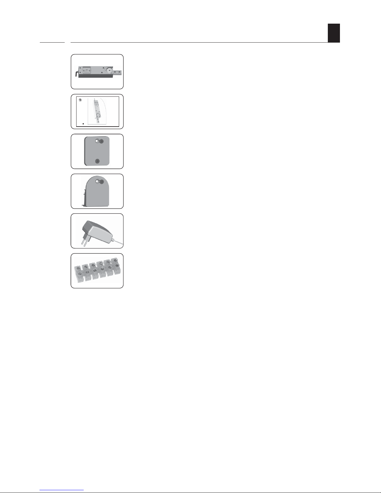
After unpacking the product, compare the
contents of the package with this list:
1 x Drive
1 x Operating instructions
1 x Operating panel lid *
1 x Toothed belt wheel cover *
1 x 24 V mains power adapter
1 x Connecting terminal
* incl. screws
1.
2.
3.
4.
5.
6.
Included in delivery
Page 6

6
GB
i
Correct usage
Use the RolloSystems T2 exclusively:
◆ To open and close sliding doors and sliding shutters of the respective permissible maximum
weight, in private households.
◆ According to the information and security requirements given in this manual.
Any other usage would be regarded as improper use.
◆ Single-wing or double-wing sliding doors with a maximum weight of 80 kg.
◆ The sliding door or sliding shutter fittings must correspond to DIN 1527 load class 6 (length
of useful life) and load class 3 (initial friction).
Permissible sliding doors / sliding shutters
i
Operating conditions
i
◆ An easily accessible 230 V/50 Hz socket must be available at the installation site.
◆ Only install the mains power adapter in dry rooms.
◆ It should be possible to easily open and close the sliding door or sliding shutter by hand, the
door or shutter should not stick, and must be installed horizontally.
◆ The sliding door or sliding shutter must be of a design with solid (fixed, immovable) end
stops.
Page 7

7
GB
i
The RolloSystems T2 must not be used:
◆ Without making the required adjustments for type of mounting/speeds (see page 27) and
end points (see page 22).
◆ To operate doors that are subject to building inspectorate specifications:
- Fire doors
- Smoke control doors
- Escape doors
- Doors in escape routes etc.
Incorrect assembly may lead to risk of injury
The manufacturer is not liable for damages resulting from incorrect or improper use (see page
47).
Observe the instructions in the guide rail system assembly manual.
Incorrect usage
Page 8

8
GB
i
General safety instructions
Work on electrical systems entails the risk of fatal electric shock.
◆ Always remove the mains power adapter from the socket before carrying out any work on
the RolloSystems T2 or on the sliding door or sliding shutter.
The use of defective equipment can lead to personal injury and damage to
property.
◆ Never use defective or damaged equipment.
◆ Check that the drive and power unit are intact.
◆ Please contact our Customer Service (see page 48) should you discover damage to the
system.
With power-driven sliding doors/sliding shutters there is a risk of injury through
crushing or cutting of a limb at the closing edges.
◆ Please ensure that no one remains in the range of motion of the sliding door/sliding
shutter during operation.
Incorrect use leads to an increased risk of injury.
◆ Never reach into moving sliding doors/sliding shutters or into actuated components.
◆ Brief all parties involved in how to use the system safely.
◆ Keep children away from travelling sliding doors/sliding shutters whenever these are in
movement.
◆ Forbid children from playing with the sliding door or sliding shutter, or with the external
controls.
◆ Keep remote controls somewhere that prevents them being used accidentally, e.g. by children
playing.
◆ Only pass through sliding doors/sliding shutters when they are fully open and at a standstill.
If safety attachments are defective or out of operation there is a risk of injury
or damage to property.
◆ Set the speed according to the type of mounting.
◆ Keep the path of travel free of foreign bodies, (e.g. ice, snow, dirt and stones).
Page 9

9
GB
i
Functional description
The RolloSystems T2 can be used to automate standard sliding doors/sliding shutters. The system
is assembled using the corresponding assembly set.
Simple menu navigation for rapid installation
Simple menu navigation enables the system to be installed rapidly and all major parameters to be
adjusted. With its wide range of setting options, the drive can be adapted to site-specific conditions
and individual requirements.
Installation is also made easier by automated sequences. For example, the end points are automatically learned and saved.
Gentle motion sequences lessen wear and tear
The movement of the sliding door/sliding shutter is initiated with a soft start, and before the end
point is reached the drive switches to soft stop so that the movement ends slowly.
Safety functions
An obstacle detection function monitors the movement of the sliding door/sliding shutter for
malfunctions (see below). Additionally the drive can be manually decoupled should a malfunction
occur (e.g. in the event of power failure).
Power supply
The sliding door drive is operated by means of 24 V safety low voltage, so it is supplied with a
corresponding 24 V power unit which can be plugged into any 230 V / 50 Hz power socket.
Flexible connection options for additional operating units
The RolloSystems T2 has two control inputs and one 12 V output for connecting external sensors,
motion detectors, tread sensors and other pulse sensors.
Definition of terms
For simplicity, the term „sliding unit“ will be used in the following chapters instead of „sliding
door/sliding shutter“.
Page 10

10
GB
i
Functional description / Obstacle detection
The drive features an automatic obstacle detection sensor.
If the sliding unit should encounter an obstacle when opening or closing, the drive stops automatically
and travels approx. 30 cm in the opposite direction.
Display as soon as an obstacle is identified.
NOTE
In certain circumstances, the obstacle detection sensor may incorrectly identify an obstacle, in
which case proceed as detailed on page 42.
Functional description / Manual decoupling
i
The RolloSystems T2 has a manual decoupling function.
In the event of a malfunction (e.g. power failure) the sliding unit can be decoupled from the drive
and moved by hand by giving it a hefty push. To recouple the sliding unit it has to be brought back
into position in relation to the toothed belt connector. When correctly positioned the follower will
clearly latch into the toothed belt connector.
Click
Page 11

11
GB
i
Overview of features
RolloSystems T2 functions and features
◆ Automatically learns the end points
◆ Automatic obstacle detection
◆ Automatic synchronisation after power failure
◆ Adjustable obstacle detection sensitivity
◆ Adjustable speeds (for opening and closing)
◆ Adjustable automatic closing
◆ Integral receiver for manual transmitter (433 Mhz Keeloq and radio motion detector)
◆ Adjustable Soft Start and Soft Stop
◆ Power supply with 24 V safety low voltage
◆ 12 V output (e.g. as power supply for motion detector and sensor)
◆ Adjustable inputs for connecting control units
Page 12

12
GB
Important information prior to assembly and installation
Before assembly, check:
◆ ... whether your sliding unit is suitable for the drive and
◆ ... that the sliding unit/ the mechanism is in perfect mechanical working order. It should be
possible to open and close the sliding door or sliding shutter easily.
Check the weight of the sliding unit
◆ The permissible total weight of 80 kg should not be exceeded, otherwise the drive may not
operate faultlessly. Therefore check the total weight of the sliding unit(s) before assembly
(e.g. with bathroom scales).
Page 13

13
GB
Electrical connection / Power supply
The power is supplied via the 24 V mains power adapter provided.
NOTE
Note the information given on the 24 V mains power adapter’s type plate. It gives all the information
necessary for connecting the drive.
Assignment of the connecting
cable on the 24 V mains power
adapter
Assignment of the connecting
cable on the drive
The polarity of the power unit cable is shown by a marking:
Wire Polarity Drive cable
not marked = + 24 V green (5)
marked = GND (ground) brown (1)
+ 12 V output (power supply for motion detector and sensor)
The drive has a + 12 V output for connecting external sensors and motion detectors.
Colour assignment of the drive cable for the + 12 V
output
Drive cable Assignment
pink (6) = + 12 V output (max. 70 mA)
grey (2) = GND (ground)
Page 14

14
GB
Brief description of control inputs A and B
Connection of external controls
The drive has two control inputs A
and B for connecting various external controls,
such as:
◆ Sensor
◆ Motion detector etc.
◆ Roller shutter switch
Colour assignment of the drive cable for the control inputs
Drive cable Assignment
white (3) = control input A
yellow (4) = control input B
Setting the function of the control inputs (see page 34)
The function of each control input can be set as needed. This is done in menus and .
The following functions can be set:
◆
Off
◆
NC mode (potential-free opener contact)
◆
NO mode (potential-free closer contact)
◆
Pause mode (potential-free closer contact)
◆ Opening, potential-free closer contact
(dead-man operation, e.g. for roller shutter switches)
◆
Closing, potential-free opener contact
(dead-man operation, e.g. for roller shutter switches)
Permissible voltage for control inputs
Input voltage: 9 V to 24 V
Input resistance: > 47 kΩ
IMPORTANT
Control inputs not in use must be connected to GND, brown (1) or grey (2).
Page 15
15
GB
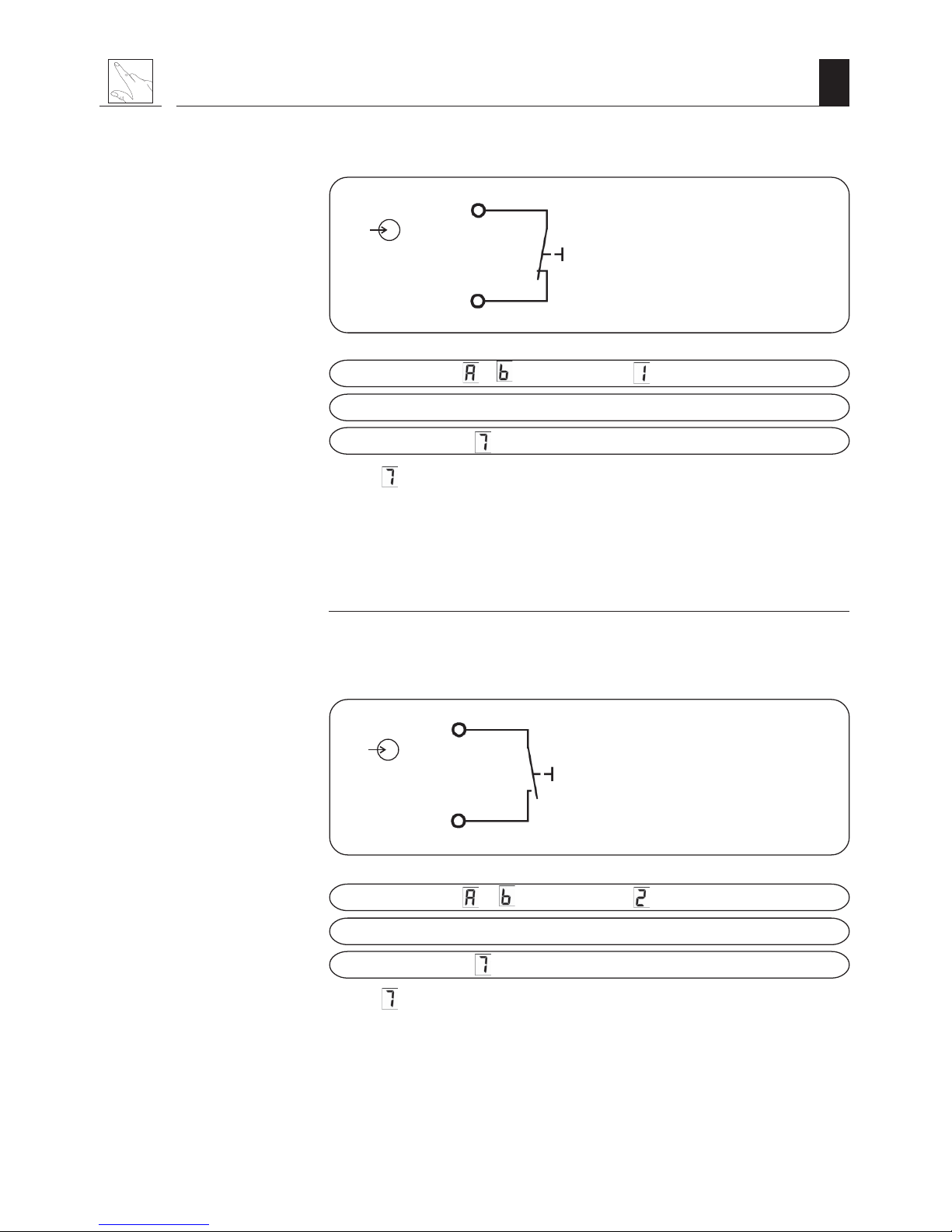
Connecting a potential-free opener contact as per + 12 V (NC mode).
pink (6)
12 V
Control input
Potential-free
opener contact
Setting mode in menu
or :
Switching signals: OPEN - STOP- CLOSE - STOP...
Switching signal if menu is enabled: OPEN (opening)
(Menu = Automatic closing)
NOTE
When connecting several motion detectors or sensors to this input, the switch contacts in this
mode must be switched in series.
Connecting a potential-free closer contact as per + 12 V (NO mode).
pink (6)
12 V
Control input
Potential-free
closer contact
Setting mode in menu
oror
oror
or
:
Switching signals: OPEN - STOP- CLOSE - STOP...
Switching signal if menu
is enabled: OPEN (opening)
(Menu
= Automatic closing)
NOTE
When connecting several motion detectors or sensors on this input, the switch contacts in this
mode must be switched in parallel.
Connecting an external sensor or motion detector
Page 16

16
GB
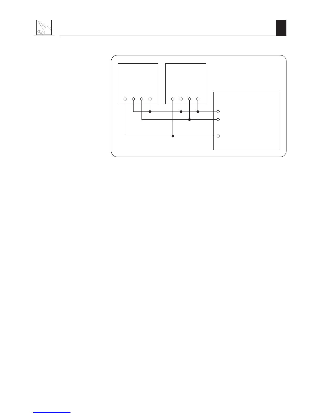
Connecting a potential-free roller shutter switch with + 12 V.
pink (6)
12 V
Control input
A
white (3)
B
yellow (4)
Potential-free closer
contact of a roller shutter
switch
(example)
Setting mode in menu
and
: (when both inputs are in use)
Control input A
(open)
Control input B
(close)
Switching signals: OPEN (opening) or CLOSE (closing)
NOTE
◆ Dead-man operation
The drive moves the door in the corresponding direction for as long as the signal persists. If
the signal lapses during travel the drive stops.
◆ Control inputs A
and B must not both be set to mode
and . If the required
application can be implemented using only one control input, the second control input can be
set to any other function.
Further applications:
◆ Automatic operation with the aid of a thermostat.
For this function a thermostat must be connected via a changeover contact.
◆ Automatic operation with the aid of a timer control (e.g. a 230 V roller
shutter control).
For this function the roller shutter control must be connected using a cut-off relay.
CAUTION
The cut-off relay must maintain the necessary safety barrier between the 230 V mains and
the low-voltage side.
Connecting a roller shutter switch
Page 17

17
GB
Connecting the ArtMotion motion detector
Connecting the motion detector in closer mode (NO)
The radar motion detector ArtMotion is recommended for use with the RolloSystems T2. It must
be operated in „High Active“ mode – refer to the motion detector assembly and operating
instructions.
Settingof the respective control inputs:
Connecting two ArtMotion motion detectors in closer mode
+ 24 V
GND
+
ArtMotion
Power
Supply
Potentialfree
output
white white
brown
brown
green
green
yellowyellow
Cable
green (5)
brown (1)
grey (2)
white (3)
or
yellow (4)
Controlinput
RolloSytems T2
ArtMotion 1 ArtMotion 2
RolloSystems T2
yellow
green
brown
white
yellow
green
brown
white
green
brown/grey
yellow
white
Control input
+ 24 V
GND (ground)
If an input is already assigned for a sensor or other device, the motion detector can be
connected to an input in parallel (see page 18).
Page 18
18
GB
Connecting the ArtMotion motion detector
Parallel connection of two ArtMotion motion detectors in closer mode
ArtMotion 1 ArtMotion 2
RolloSystems T2
green
brown/grey
yellow
or
white
+ 24 V
GND (ground)
Control input
amarillo
verde
marrón
blanco
amarillo
verde
marrón
blanco
Page 19

19
GB
Plus key
OK
OK key
Minus key
LED display
Calling up functions / Setting assistance / Operation
The drive has three operating keys and an LED display. All functions can be accessed and the
required settings made using the operating keys. The LED display provides information on the
function selected and the status of the function.
Drive menu structure
All necessary settings can be made in the drive control menu. Functions are selected via the
menu. The following table gives a brief introduction to the individual functions:
/
End point search
Reverse running direction
Set braking distance
Set sensitivity
Set mounting mode / opening speed
Set closing speed
Set automatic closing
Acoustic signal
Push mode
Set function of control inputs A
and B
Clear (restore factory settings)
Activate radio motion detector
Activate/deactivate manual transmitter
Page 20

20
GB
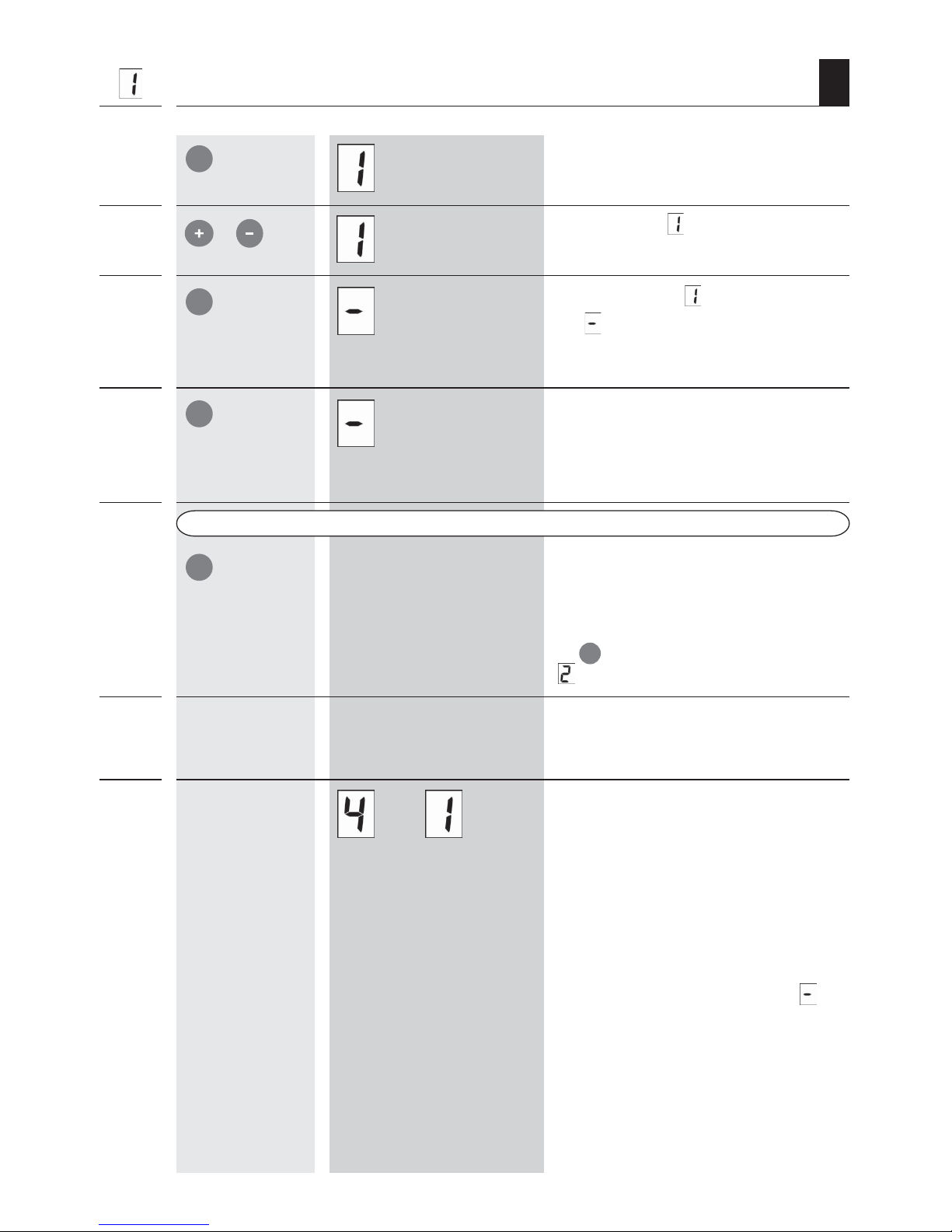
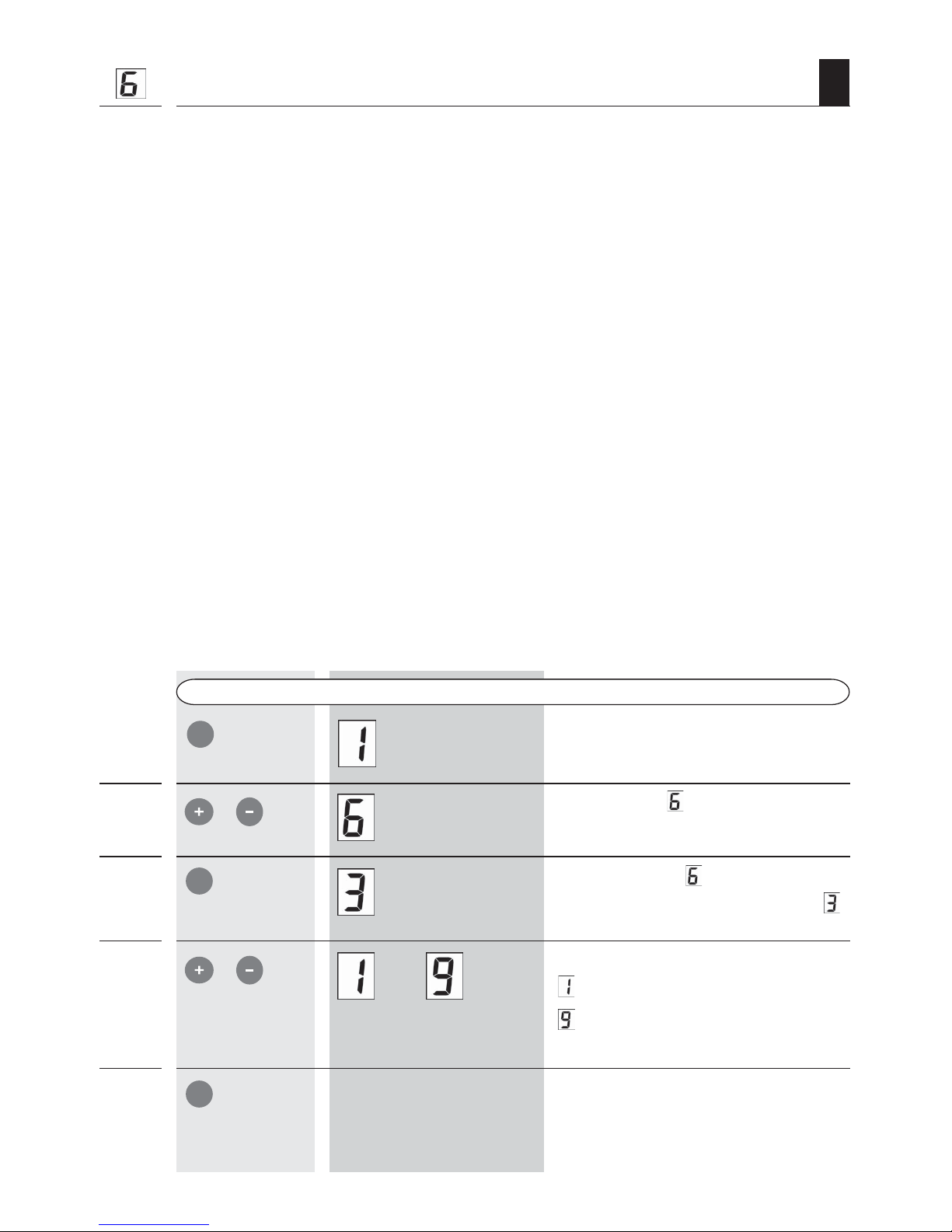
Calling up the menu and selecting a function (Example)
Display after plugging the power unit
into a 230 V socket.
The drive is idle (in standby mode).
1.
OK
Press for two
seconds
Select a function.
e.g.
„Function of control input A “
3.
/
4.
5.
/
Keys
LED display
Call up the menu.
Confirm the selection and switch to
setting mode.
The display flashes.
Set the required function.
e.g.
(closer contact, NC)
Return to menu.
Exit the menu.
The drive then returns to idle.
NOTE
If no key is pressed for 30 seconds, the drive automatically returns to idle mode.
Changes to settings are nevertheless saved.
6.
7.
2.
Press for two
seconds
OK
OK
OK
Page 21

21
GB
Installation sequence
1. / 2. / 3. ...
IMPORTANT
It is essential that the installation sequence is followed
It is essential that the installation sequence shown here and described in the following section is
complied with. Deviation from this or changes to some settings would require the system to be
reinstalled.
1. Before assembly check the weight of the sliding unit (max. 80 kg).
2. Assemble and connect the drive.
3. Menu
, activate a manual transmitter (optional)
4. Menu
, activate the search run for the end points.
5. Check the running direction (1
st
run = opening).
6. If necessary, menu , reverse running direction and repeat the search run.
7. Connect the required operating units (sensor, motion detector etc.).
8. Menu
/ , set the control inputs.
9. Menu
- activate further manual transmitters (optional)
or
Menu
, activate a radio motion detector.
10. Menu
, set an automatic closing time (optional).
Page 22

22
GB
Automatic end point search / Brief explanation
To ensure smooth operation, solid (fixed, immovable) end points must be available for the
drive in both travel directions.
Automatic search run
The drive independently learns both end points.
IMPORTANT
Never try to simulate end points (e.g. by stopping the sliding unit with your hand or foot), as
these temporary end points would be lost after a power failure, for example, due to the
automatic synchronisation runs (see page 43).
Automatic reference run
Once the two end points have been found, the drive automatically carries out four reference
runs, in order to set the amount of force required to move the sliding unit, depending on the
specific conditions at the installation site.
The automatic reference run is a potential source of danger.
During the automatic reference runs the force limitation is not yet operational, therefore it is
important to ensure that no-one is in the path of travel of the sliding unit when these runs are
being performed.
NOTE
If the end point search is too sensitive, or not sensitive enough, this can be adjusted in menu
item
(see page 26).
Manual adjustment of end points
During the end point search, the drive stops as soon as a control signal is sent during the automatic
end point search (e.g. from an external sensor or motion detector, or when the
OK
key is
pressed).
The following situations may occur which may lead to problems:
◆ The current position of the sliding unit is then saved as an end point.
◆ Automatic synchronisation after power failure is switched off.
◆ The end stops may be lost after a power failure, should the position of the sliding unit
have changed (e.g. by pushing).
Page 23
23
GB
Starting automatic end point search
Keys
LED display
2.
/
3.
4.
Press for three
seconds
6.
7.
. . .
5. Press
repeatedly
Only in the event that the direction of travel is incorrect, otherwise continue from number 6
Press for two
seconds
1.
OK
OK
OK
OK
Call up the menu.
Select function „Find end points“.
Confirm function
„Find end points“.
The
symbol appears and flashes.
The search run starts, the sliding door/
sliding shutter opens.
Release the key as soon as the drive starts up. The search
always begins in an „opening“ direction.
Cancel „Find end point“.
IMPORTANT
If the end point search starts in a „closing“ direction,
you should cancel the search run by repeatedly pressing
the
OK
key, then reverse the direction of travel in menu
(see page 24).
The drive carries out the automatic end point
search.
Completion of four automatic reference
runs.
As soon as the two end points have been found and
saved, four automatic reference runs are performed to
ascertain the force setting required.
NOTE
◆ The number of runs remaining are shown in a
flashing display.
◆ After the reference run the drive is idle
.
Page 24

24
GB
Reversing the running direction
2.
/
3.
Keys
LED display
Press for three
seconds
4.
5.
Press for two
seconds
1.
The running direction of the sliding unit is dependent on the following factors and may need to
be adjusted:
◆ on the installation situation (right-hand / left-hand installation) and
◆ on the connection of the sliding unit to the toothed belt (front or rear toothed belt).
NOTE
Valid end points have to be learned so that the direction of travel can be checked. Then for every
movement of the door, the direction of travel is shown in the LED display as follows:
Door travel direction LED display
Opening = (open)
= Also on the first search run to learn the end points.
Closing = (close)
IMPORTANT
Repeating end point search and reference runs.
When reversing the running direction, the end points and the reference run settings are automatically
deleted and must be repeated (see page 22/23).
OK
OK
OK
OK
Call up the menu.
Select function
„Running direction“.
Confirm selection
.
The current status of the function is shown and flashes
(e.g.
)
= Reversal of running direction is deactivated.
= Reversal of running direction is activated.
Reverse running direction.
Return to menu.
Page 25

25
GB
Setting the braking distance
2.
/
3.
Keys
LED display
4.
5.
/
. . .
Press for two
seconds
1.
Call up the menu.
Select function
„Braking distance“.
Confirm selection .
The braking distance set will flash on the display.
Set braking distance.
= short braking distance
= long braking distance
= factory setting
Return to menu.
OK
OK
OK
The braking distance helps to determine how strongly the drive or the sliding unit brakes before
the end points are reached. The braking distance can be adjusted to correspond to the weight of
the sliding unit (door panel or shutter) and the running performance.
NOTE
If the sliding unit stops suddenly while braking then travels in the opposite direction, the braking
distance has been set incorrectly. As too much force is used in braking when this happens, obstacle
detection is triggered and
is shown in the display.
It may be necessary to carry out a series of trial runs to set the braking distance correctly.
Weight of sliding unit Braking distance
light = short braking distance
heavy = long braking distance
factory setting =
IMPORTANT
Repeating end point search and reference runs.
Every time the braking distance is altered the end points, as well as the reference run settings,
are automatically deleted and must be repeated (see page 22/23).
Page 26
26
GB
Setting the sensitivity of obstacle detection
2.
/
3.
Keys LED displays
4.
5.
/
. . .
Press for two
seconds
1.
OK
OK
OK
With this function you can set the level of sensitivity for triggering obstacle detection.
Description Setting
high sensitivity =
low sensitivity =
factory setting =
IMPORTANT
When using the drive outside, you should set the sensitivity low enough that frost and wind do
not disrupt normal operation.
Call up the menu.
Select function „Sensitivity of
obstacle detection“.
Confirm selection
.
The current level of sensitivity is shown and flashes.
Set the required level of sensitivity.
= high sensitivity
= low sensitivity
= factory setting
= external use
Return to menu.
Page 27
27
GB
Setting speeds, automatically and manually
Automatically setting of the speed by selecting the type of mounting:
The speed can be set automatically contingent on the type of mounting (running into the wall or
running on the wall) in order to reduce the risk of injury (through impact or crushing) at the
closing edges of a sliding door or sliding shutter.
Type of mounting Setting
The sliding unit runs into the wall. =
The sliding unit is mounted on the wall. = (factory setting)
Correlation between type of mounting and speed
Setting Description
= fast opening / slow closing
= slow opening and closing
NOTE
Speed setting in compliance with safety standards.
The speed is set at the factory so as to comply with the maximum forces for a sliding door or for
a sliding shutter, as set out in the relevant safety standards, where the maximum weight of the
sliding unit is 80 kg. If necessary, the speed can be adjusted (raised) if lighter sliding units are
used.
Manual adjustment of the opening speed.
Alternatively the opening speed can also be set manually (see page 28).
IMPORTANT
Repeating the end point search and reference runs.
Every time the type of mounting or the speed is altered, the end points, as well as the reference
run settings, are automatically deleted and must be repeated (see page 22/23).
Extending the braking distance.
When the opening speed has been increased it may be necessary to extend the braking distance
in order to ensure smooth operation (see page 25).
Page 28

28
GB
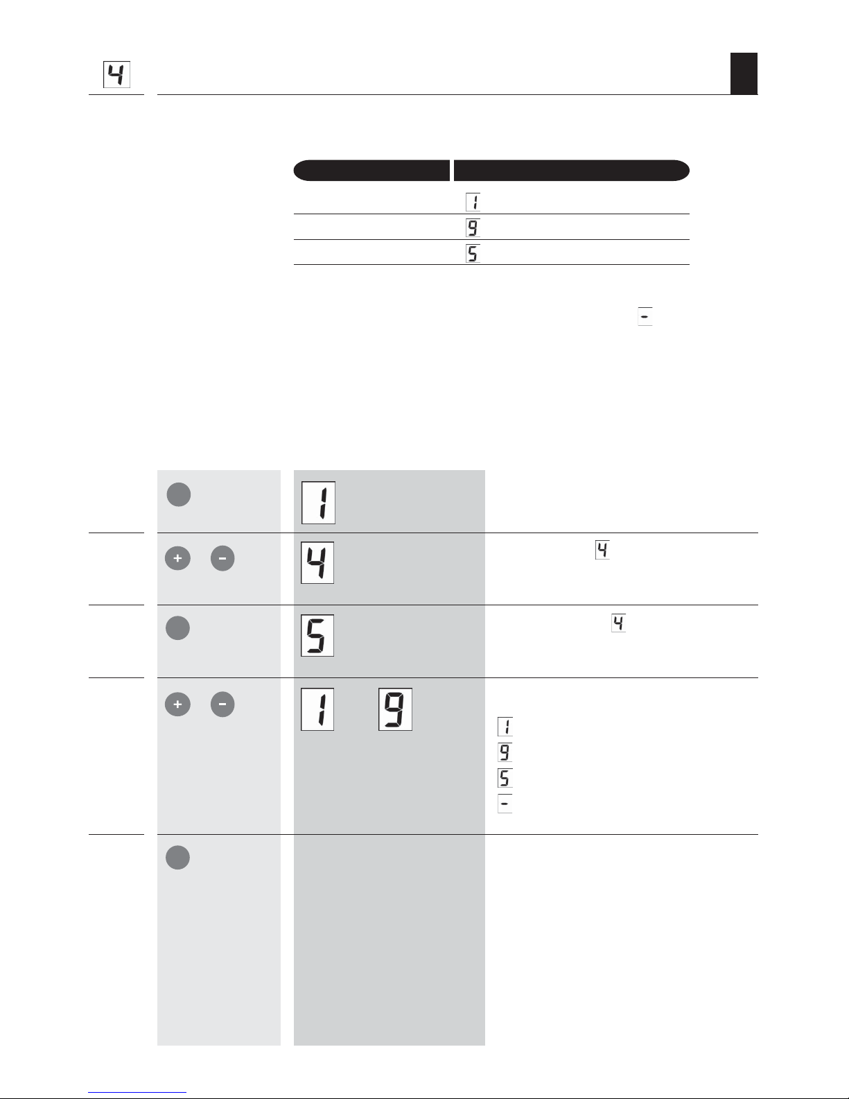
1. Automatic setting of the speed according to the type of mounting
Keys
LED display
2.
/
3.
4.
5.
/
. . .
Press for two
seconds
1.
2. Switching to manual setting of the opening speed
LED display
OK
Press for two
seconds
1.
+
Press for three seconds
simultaneously
2.
/
3.
4.
+
OK
OK
OK
OK
Keys
Call up the menu.
Select function
„Mounting type“.
Confirm selection .
The current type of mounting is shown and flashes.
Set the required type of mounting.
= The sliding unit runs into the wall.
= The sliding unit is mounted on the
wall (factory setting).
Return to menu.
Call up the menu.
Select function „Mounting type“.
Confirm selection .
The current type of mounting is shown and flashes.
Switch to manual setting of the opening
speed.
A signal sounds and the current speed is shown and
flashes (e.g. 4).
Page 29
29
GB
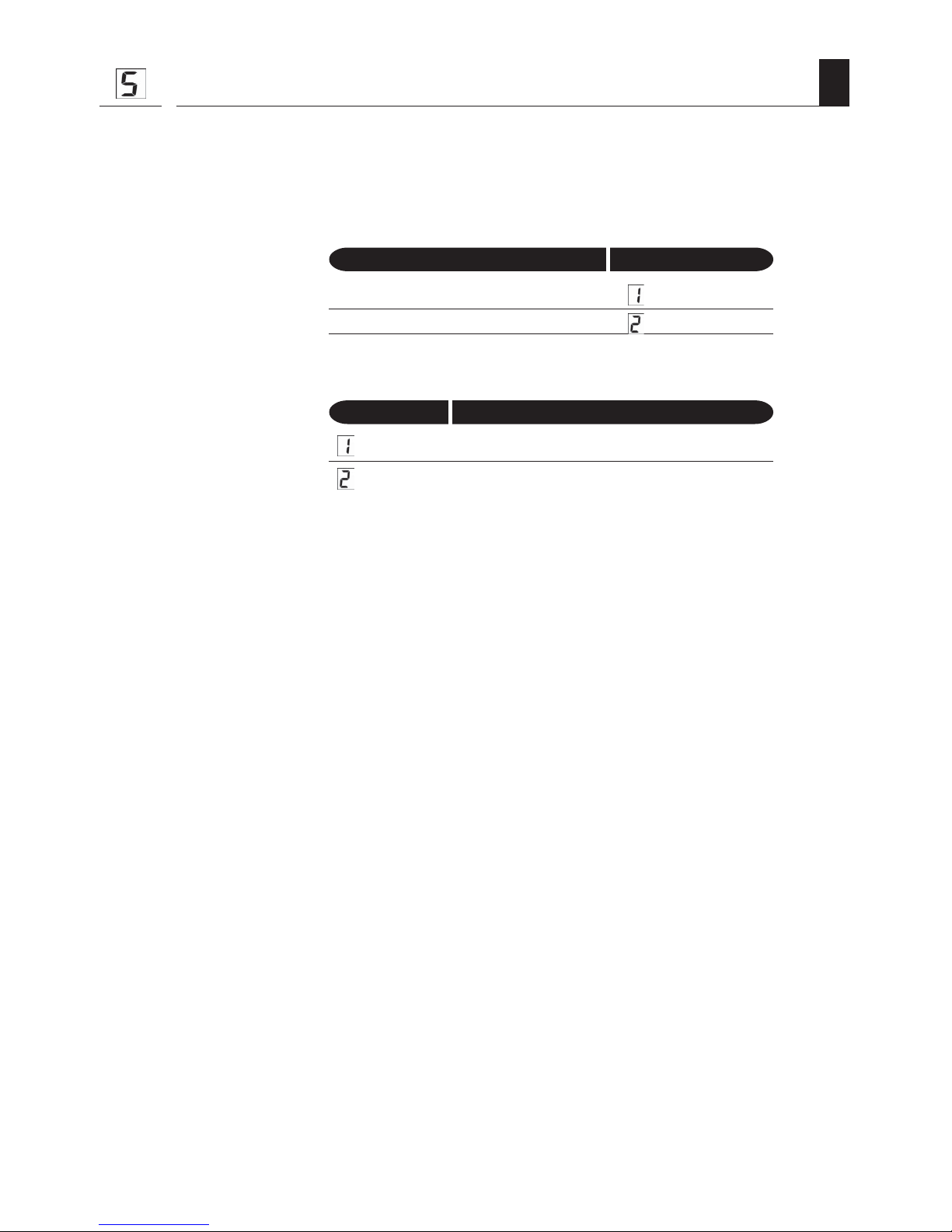
2. Switching to manual setting of the opening speed
5.
6.
Keys
LED display
. . .
/
+
Press for three seconds
simultaneously
Keys
LED display
2.
/
3.
4.
/
5.
6.
+
. . .
3. Switching to automatic speed setting according to the type of mounting
Press for two
seconds
1.
OK
OK
OK
OK
Set the required opening speed.
= slow speed
= high speed
Return to menu.
NOTE
Subsequently the closing speed can be
set in menu item 6 (see page 30).
Call up the menu.
Select function
„Mounting type“.
Confirm selection .
The current speed is shown and flashes (e.g. 4)
Switch to manual setting of opening
speed.
A signal sounds and the current type of mounting is
shownand flashes (e.g. 2).
Set the required type of mounting.
= The sliding unit runs into the wall.
= The sliding unit is mounted on the wall
(factory setting).
Return to menu.
Page 30
30
GB
Setting the closing speed
Keys
LED display
Manual setting of the closing speed.
2.
/
3.
4.
/
5.
. . .
Press for two
seconds
1.
Automatic setting of the closing speed, depending on the type of mounting
selected.
If automatic speed setting by selecting the type of mounting has been activated, the closing
speed is permanently set (depending on which type of mounting has been selected). In this
case it is not possible to set the closing speed separately.
Conditions for manually setting the closing speed.
If manual selection of the opening speed has been activated, it is also possible to manually set
the closing speed.
IMPORTANT
Repeating the end point search and reference runs.
Every time the closing speed is altered the end points, as well as the reference run settings, are
automatically deleted and must be repeated without fail (see page 22/23).
Extending the braking distance.
When the closing speed has been increased it may be necessary to extend the braking distance
in order to ensure smooth operation (see page 25).
Call up the menu.
OK
OK
OK
Select function „Closing speed“.
Confirm selection .
The current speed value is shown and flashes (e.g.
).
Set the required closing speed.
= slow speed
= high speed
Return to menu.
Page 31
31
GB
Activating automatic closing
Automatic closing.
This function ensures that the sliding unit automatically closes once it has been opened.
Setting variable closing times.
You can set different closing times to suit your individual needs.
Setting Closing time
= deactivate automatic closing time
= 3 seconds
= 6 seconds
= 10 seconds
= 15 seconds
= 21 seconds
= 28 seconds
= 37 seconds
= 48 seconds
= 60 seconds
Function of control inputs / in mode and when the „Automatic
closing“ function is activated.
Switching signal from a sensor or motion detector: OPEN (door opens)
After the set closing time: CLOSE (door closes)
Function of control inputs
/ in mode and when the „Automatic
closing“ function is deactivated.
Switching signal from a sensor or motion detector: OPEN - STOP- CLOSE - STOP...
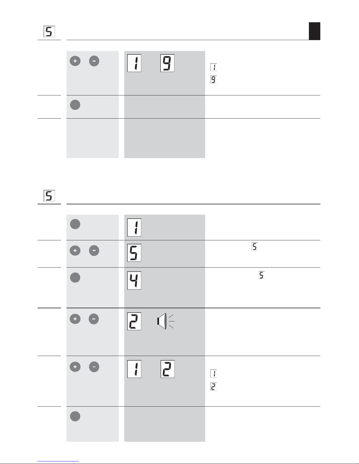
Page 32

32
GB
2.
/
3.
4.
/
5.
. . .
Activating automatic closing
Press for two
seconds
1.
Keys
LED display
2.
/
3.
4.
/
5.
Switching acoustic signal on/off
An acoustic signal sounds as a warning before every run. The signal can be switched off if necessary.
. . .
Press for two
seconds
1.
OK
OK
OK
OK
OK
OK
Call up the menu.
Select function „Automatic closing“.
Confirm selection .
The current status of the function/ the current closing
time is shown and flashes (e.g.
).
Set the required closing time.
... see table on page 31.
or
Deactivate the function
.
Return to menu.
Call up the menu.
Keys
LED display
Select function „Acoustic signal“.
Confirm selection
.
The current status of the function is shown and
flashes.
Set the required function.
= acoustic signal off.
= acoustic signal on (factory setting).
Return to menu.
Page 33

33
GB
Switching Push mode on/off
When the sliding unit is mechanically moved, the drive travels in the corresponding direction. It
takes significant force to move the sliding unit, therefore this should not be the usual method of
operation.
IMPORTANT
If the sliding door/sliding shutter is fitted with a mechanical coupling this can be decoupled when
the sliding unit is pushed before the drive recognises the manual movement. In this case the Push
mode does not function.
Keys
LED display
2.
/
3.
4.
/
5.
. . .
Press for two
seconds
1.
OK
OK
OK
Call up the menu.
Select function
„Push mode“.
Confirm selection
.
The current status of the function is shown and flashes.
Set the required function.
= Push mode off.
= Push mode on (factory setting).
Return to menu.
Page 34

34
GB
Setting the function of control inputs A and B
The function of each control input can be set as needed. This is done in menus and .
The following functions can be set:
Setting Function
= Off (factory setting)
= NC mode (potential-free opener contact)
= NO mode (potential-free closer contact)
= Pause mode
= Open (dead-man operation, e.g. for roller shutter switches)*
= Close (dead-man operation, e.g. for roller shutter switches)*
* only potential-free closer contacts for a roller shutter switch
Brief description of functions
= Off
The control input is switched off (factory setting). For example, a motion detector can
be switched off if needed, without having to disconnect it.
= NC mode
A potential-free opener contact (external sensor or motion detector) can be connected
to the control input.
= NO mode
A potential-free closer contact (external sensor or motion detector) can be connected
to the control input.
Page 35

35
GB
Setting the function of control inputs A and B
Brief description of functions
3 = Pause mode
◆ The sliding unit can be arrested in its current position by pressing the key provided
for this (Pause key). This makes it possible to conveniently clean the sliding unit
and the door/window opening, for example. Control signals from other external
controls (manual transmitter, external sensor, motion detector etc.) are suppressed.
◆ Press the Pause key again to switch the Pause mode off.
Signals
◆ 4 x acoustic signals as soon as Pause mode is switched on or off.
◆
when Pause mode is active
NOTE
◆ When Push mode is activated (see page 33), Pause mode is switched off as
soon as the sliding unit is moved manually.
◆ If function
„Automatic closing“ is active, the sliding unit is closed approx. 6
seconds after Pause mode is switched off.
4 = Open signal (closer contact)
and
5 = Close signal (closer contact)
These functions are used for connecting a roller shutter switch with potential-free closer
contacts or a control with comparable switching pulses.
Dead-man operation
The drive moves the sliding unit in the corresponding direction for as long as the signal
persists. If the signal lapses during the run the drive stops.
NOTE
As both control inputs A
and B
are used for the application both control
inputs should be configured accordingly.
◆ Control input A
= mode 4 (open)
◆ Control input B
= mode 5 (close)
Control inputs A
and B do not both have to be set to mode and . If
the application can be implemented using only one control input, the second control input
can also be set to any other function.
Page 36

36
GB
Keys LED display
2.
/
3.
4.
/
5.
. . .
Press for two
seconds
1.
or
Setting the function of control inputs A and B
OK
OK
OK
Call up the menu.
Set the required function or
„Control inputs“.
Confirm selection
or .
The current status of the function is shown and flashes,
e.g.
.
Set the required mode (see page 34).
Return to menu.
Page 37

37
GB
Clear / Deleting all settings / Viewing software version
Keys
LED display
2.
/
Press for two
seconds
1.
3.
4.
3 seconds
5.
OK
OK
OK
OK
A reset deletes all settings including the activated manual transmitter and radio motion
detector. After that the factory settings apply again (see page 46).
IMPORTANT
After a reset has been carried out all settings must be entered again.
NOTE
Press the OK key briefly to exit the function without performing a reset.
Call up the menu.
Select function
„Clear“.
Confirm selection .
First the current software version is shown briefly, e.g.
2.
Then the symbol shown appears and flashes.
Carry out the reset.
All settings are deleted. The drive is reset to its factory
settings (see page 46).
Return to menu.
Page 38

38
GB
Activating/deactivating a radio motion detector
Keys
LED display
Activating a radio motion detector
2.
/
3.
5.
4.
6.
Press for two
seconds
1.
OK
OK
OK
If required you can also control the drive with a radio motion detector.
IMPORTANT
◆ Only one motion detector channel can be activated.
◆ Before being activated, any additional motion detectors must be set to the same radio code
as the first radio motion detector (see the operating instructions for the respective radio
motion detector).
Also refer to the installation and operating instructions for the radio motion
detector .
Call up the menu.
Select function
„Activate radio
motion detector“.
Confirm selection
.
The current status of the function is shown and flashes.
= No radio motion detector is yet activated.
Insert batteries into the radio motion
detector.
Please refer to the operating instructions for the
motion detector in question.
When activation is successful the
display changes
= A radio motion detector is activated.
Return to menu.
Page 39

39
GB
Deactivating a radio motion detector
2.
/
+
Press for three seconds
simultaneously
4.
3.
5.
Press for two
seconds
1.
Activating/deactivating a radio motion detector
Keys
LED display
OK
OK
OK
Call up the menu.
Select function .
Confirm selection
.
The current status of the function is shown and flashes.
A successful deactivation is indicated by
a flashing display.
Return to menu.
Page 40

40
GB
Activating/deactivating a manual transmitter
Up to 9 manual transmitters can be activated.
Keys
LED display
Activating a manual transmitter
2.
/
3.
5.
4.
6.
Press for two
seconds
1.
Call up the menu.
Select function
„Activate manual
transmitter“.
Confirm selection .
The number of manual transmitters activated flashes in
the display.
= No manual transmitter is yet activated.
Activate the required manual transmitter.
When activation is successful the display
changes
= The number of manual transmitters activated
(e.g. 2) is displayed.
Return to menu.
OK
OK
OK
Page 41

41
GB
+
Press for three seconds
simultaneously
Deactivating all manual transmitters
2.
/
4.
Press for two
seconds
1.
3.
5.
Activating/deactivating a manual transmitter
Keys
LED display
OK
OK
OK
Call up the menu.
Select function
.
Confirm selection
.
The number of manual transmitters activated flashes in
the display.
Deactivate all activated manual
transmitters.
Successful deactivation is indicated by a flashing display.
Return to menu.
Page 42

42
GB
Obstacle detection / What to do if...?
1.
2.
3.
4.
5.
6.
... the drive stops unexpectedly and travels in the opposite direction?
Possible cause: The braking distance is too short or the speed is too high for the
sliding unit.
Solution: Extend braking distance or reduce speed
(see page 25/27).
Possible cause: The end points are incorrectly set.
Solution: Repeat automatic end point search (see page 23).
Possible cause: The sensitivity level for obstacle detection has been set too high.
Solution: Reduce sensitivity level for obstacle detection
(see page 26).
Possible cause: The sliding unit is running jerkily rather than smoothly and is
sticking.
Solution: Clear possible sticking places and remove any dirt.
Possible cause: The guide rails are not mounted level, so that the sliding unit has
to run uphill.
Solution: Correct the installation of the guide rails.
Possible cause: If system is mounted outside:
Guide rails or toothed belt are iced up.
Solution: Remove ice from the guide rails.
Page 43

43
GB
Automatic synchronisation at the „Closed“ end point
i
Automatic synchronisation after power failure
Automatic end point search (synchronisation)
If the end points were set by means of the automatic search run, after a power failure the end
points are automatically searched for again (synchronisation). To do this, the drive carries out up
to four synchronisation runs, depending on circumstances, until the end points have been definitively
located.
NOTE
Deactivating automatic synchronisation.
If the end points have been set manually, automatic synchronisation after a power failure is
deactivated. This means that the end stops may be displaced after a power failure, in which case
the end points have to be reset manually.
What happens if synchronisation has been unsuccessful?
If no end points have been located after the fourth synchronisation run, the drive switches to
„Asynchronous mode“.
= Asynchronous mode is shown on the displayand flashes. Correct operation
is then no longer possible.
Repeat synchronisation by transmitting a travel command or repeat end point
settings.
To ensure smooth operation, solid (fixed, immovable) end points must be available for the
drive in both travel directions.
= LED display after successful synchronisation at the „Closed“ end point.
If the end points are identified during installation, the drive automatically synchronises at the
„Closed“ end point . This ensures that the sliding unit is always completely closed when in a
„Closed“ position.
Page 44

44
GB
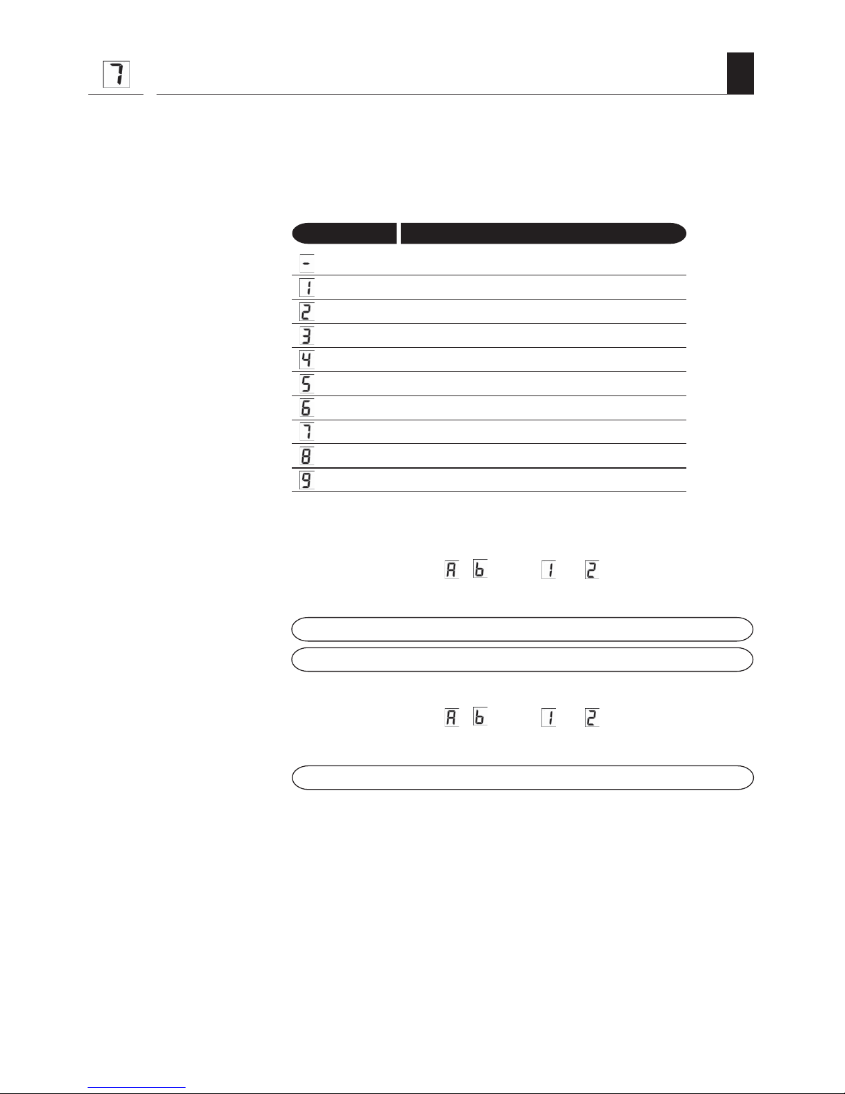
Error messages
Error messages are indicated by the LED display and a repeated acoustic signal. The LED display
first shows an „
“ and then the number (e.g. ) of the error message in question.
Display Description of error
: The configuration has been modified.
Remedy:
Perform an automatic end point search (see page 23).
: The end points are too close together.
Remedy:
Repeat an automatic end point search (see page 23).
: ◆ The drive is sticking, movement is no longer possible.
◆ The drive or the sensor electronics are defective.
Remedy:
◆ Check the toothed belt.
◆ Servicing required *
: Error in the drive electronics.
: Remedy:
◆ Servicing required *
: Error in the drive electronics.
Remedy:
◆ A reset may help (see page 37), if not
◆ Servicing required *
: The internal speed monitoring system has recognised an error.
Remedy:
◆ Repeat automatic end point search (see page 23).
◆ Servicing required * (should error re-occur)
* Please contact our Customer Service department
(see page 48).
Page 45

45
GB
TD
Technical data / RolloSystems T2
Supply voltage: 24 V safety low voltage,
via external 230 V/50 Hz mains power adapter
Drive rating: 50 W
Speed: max. 30 cm/s
Running performance: ◆ Soft Start / Soft Stop (adjustable)
◆ Automatic closing time (adjustable)
Number of control inputs: 2 ( A and B )
Safety functions: Obstacle detection / manual locking
Connecting cable: 6 x 0.34 mm2 LIYY (length = 2 m)
Protection type:
- Drive: IP55
- Power unit: IP20
Protection class:
- Drive: III
- Power unit: II
Permissible operating
temperature range: - 20° C to 50° C
Permissible door
panel weight: max. 80 kg
Dimensions (W x H x D): 48 mm x 60 mm x 200 mm
Travel: 30 cm to 3 m
Page 46

46
GB
TD
Technical data / Factory settings
Technical data / Testing
TD
Type approval to: DIN EN60335-1and DIN EN 60335-2-103
EMC testing to: DIN EN 55014-1 (emitted interference)
DIN EN 55014-2 (interference strenght)
IEC 61000-4-2, test level 4
IEC 61000-4-3, test level 3
IEC 61000-4-4, test level 3
IEC 61000-4-5, test level 3
IEC 61000-4-6, test level 3
IEC 61000-4-11
IEC 61000-4-13, test level 2
Reversal of running direction: (Off)
Automatic closing time: (Off)
Braking distance:
Sensitivity of obstacle detection:
Control input A
: (Off)
Control input B
: :
: :
: (Off)
Speed setting:
- Type of mounting: (The sliding unit is mounted on the wall)
- Opening speed:
- Closing speed:
Acoustic signal: (On)
Push mode: (On)
Automatic synchronisation: (On)
Page 47

47
GB
i
Warranty conditions
RADEMACHER Geräte-Elektronik GmbH provides a 24-month warranty for new systems that
have been installed in compliance with the installation instructions. All construction faults,
material defects and manufacturing defects are covered by the warranty.
The following are not covered by the warranty:
◆ Incorrect fitting or installation
◆ Non-observance of the installation and operating instructions
◆ Improper operation or wear and tear
◆ External influences, such as impacts, knocks or weathering
◆ Repairs and modifications by third party, unauthorised persons
◆ Use of unsuitable accessories
◆ Damage due to unauthorised electrical surges ( e.g. lightening strike )
◆ Operational malfunctions by radio frequency overlaps and other radio malfunctions
RADEMACHER shall remedy any defects, which occur within the warranty period free of charge
either by repair or by replacement of the affected parts or by supply of a new replacement unit or
one to the same value. There is no general extension of the original warranty period by delivery of
a replacement or by repair as per the terms of the warranty.
Page 48

Subject to technical modifications, misprints and errors. Diagrams subject to change.
RADEMACHER
Geräte-Elektronik GmbH & Co. KG
Buschkamp 7
46414 Rhede
info@rademacher.de
www.rademacher.de
Service:
Telefon: 01805/933171*
service@rademacher.de
* 14 ct/min aus dem Festnetz der DT AG/
Mobilfunktarif abweichend.
 Loading...