


The Accu-Series -
Accu-Pro™
Accu-Dose
Accu-kV
®
Radiation Measurement
Systems
User Guide

Radcal Corporation
426 West Duarte Road
Monrovia, CA 91016-4591 USA
USA (626) 357-7921
Fax USA (626) 357-8863
email Service@radcal.com
www.radcal.com
Radcal Part # MCD/9096
4091099 Rev:K4
Firmware V6.08 (Accu-Pro)
Firmware V7.03/V7.23 (Accu-Dose)
Firmware V5.22 (Accu-kV)
Printed: Feb 2013

INTRODUCTION ................................................................. 4
GETTING STARTED ............................................................. 6
MAKING ION CHAMBER MEASUREMENTS ..................................... 11
REFERENCE .................................................................... 12
Display ................................................................... 12
Sounds ................................................................... 13
Sensors .................................................................. 14
Main–Menu Functions .................................................... 17
Setup–Menu Functions ................................................... 19
Batteries ................................................................. 21
PERFORMANCE ................................................................ 23
Environmental conditions ................................................ 23
kV Sensors ............................................................... 23
Diode Sensors ........................................................... 25
Ion chambers ............................................................ 25
Ion Chamber Dose Timing Specifications ................................. 25
Waveform Output ........................................................ 36
Part numbers ............................................................ 36
OPERATOR MESSAGES ........................................................ 37
Self-test .................................................................. 37
Accu-kV .................................................................. 37
Ion chambers and dose diodes ........................................... 38
ACCESSORIES ................................................................. 41
XLPRO Excel add-in ...................................................... 41
90M9 mAs Sensor ........................................................ 42
90M10 mAs Sensor ....................................................... 43
10A96 Ion chamber Adapter .............................................. 44
Chamber Positioner ...................................................... 45
Accu-Pro™ System Carrying Cases ...................................... 46
APPENDIX - Mammography kVp measurements on Hologic Selenia ..................... 47
3

INTRODUCTION
The Accu-series instruments include the Accu-Pro™ for Dose and kV, the Accu-Dose for Dose only and
Accu-kV for kV only measurements. This manual is applicable to all instruments in the Accu-series.
The Accu-Pro™ system measures the characteristics of a diagnostic x-ray machine. Measurements are
processed and displayed by a microprocessor-based control unit. Sensors connect to the control unit via
a 4m cable that carries only digital signals and operating voltages to eliminate cable noise. Dose is
measured with ion chambers or solid-state detectors. Radcal Accu-kV sensors determine kV, filtration
and half-value measurements (diagnostic sensor) using differential absorption and an array of solid state
detectors. The mammographic (22-40kV) sensor Mo/Mo outputs can be corrected to W/Rh and W/Ag
anode-filter combinations (Hologic Selenia x-ray machine only).
A 13 kHz sample rate for kV measurements is used with FFT-based ripple measurements for accurate
kVp measurements on high-frequency generators.
Automatic compensation of kV measurements for filtration is available for diagnostic x-ray
measurements. This also provides estimates for filtration and half-value layer.
Stand-alone exposure measurements can be made using the Ion chamber digitizer and an ion chamber
or the dose diode digitizer and the DDX6-W or DDX6-M sensors. Using these sensors in conjunction with
the kV sensors provides dose and dose rate measurements synchronized to an x-ray pulse.
Using 40X11-W and DDX10-W or 40X10-M and DDX10-M sensors allows simultaneous dose and kV
waveform measurements
mA, mAs and mA waveform may be measured in conjunction with kV measurements using invasive or
non-invasive mA sensors.
The Accu-Pro™ operates from rechargeable NiMH or alkaline C cells.
The figure on page 46 shows the Accu-Pro™ system in its carry case.
A USB interface allows a PC to control and process measurements performed by the Accu-Pro™ system
. XLPRO, an Excel add-in, uses this capability to produce reports, graphs and to automate
measurements.
The figure on page 40 shows the pushbutton controls and the 2-line display. The connectors for the mA
sensor, USB and waveform are also visible. The battery charger interface is at the rear of the control unit.
The in-beam sensor connector is on the opposite side.
The controls include UP-arrow, DN-arrow and select pushbuttons that are used to navigate the menu
and to activate measurements. A test pushbutton provides a simulated x-ray signal so you can observe
how the measurements work. The power pushbutton provides for orderly shutdown and startup.
Measurement results are presented on the display and are available in digital form on using the USB
connection. The BNC provides calibrated real-time kV, dose or mA waveforms.
4

Accu-Pro™ Diagnostic Ion Chamber and kV Sensor Components
A. Accu-Pro™ (9096) Control Unit
B. 40x12-W Diagnostic Range kV Sensor
C. 10X6-6 Ion Chamber Sensor
D. Positioner
E. 9660 Ion Chamber Digitizer
F. 90C6-4 Sensor Cable
5

GETTING STARTED
This describes initial assembly and operation of an Accu-Pro™ system comprising a control unit, sensor
cable, diagnostic kV sensor and a 6cc ion chamber with an ion-chamber digitizer.
IMPORTANT: Stabilization is required before making any ion chamber measurements.
Stabilization is best done by putting the unit in Dose Rate mode/High Sensitivity and waiting for 3
minutes. See page 11 for details.
Connect the sensor cable to the control unit
:
Insert the rectangular connector on the sensor cable into
the socket on the right side of the instrument with the
Radcal logo facing you. It will click into place. To remove
it, pinch the levers on the side of the connector and pull
back.
Connect the kV sensor to the sensor cable
:
Hold the round connector by the rubber strain relief
and engage the kV sensor by rotating the connector
until it aligns with the mating socket on the sensor and
they move to engage, then press the connector. It
should click into place. To disconnect, pull straight
back on the ring, not on the strain relief, and the
connector will unlatch. Never attempt to unscrew the
connector.
Sensor cable connection
Connect the Ion chamber
Connect the ion chamber to the larger
circular connector on the Ion chamber
digitizer. Align the red dots and push the
connector until the mating surfaces
contact one another. Connect the sensor
cable to the smaller connector in the same
fashion.
kV sensor connection
Ion chamber connection
6

Connect the battery charger:
Connect the charger to the control unit
and plug it into an ac outlet. The charge
indicator should turn on orange indicating
the battery is being charged. The
instrument can operate while the battery
is being charged.
7

Turn on the Accu-Pro™:
Press the green power button. A set of vertical rectangles marches across the display to assure it is
operating, the calibration date is displayed, and self-test is performed. During self-test the control unit
reads the type and calibration factors of each sensor, measures the ion chamber temperature and the
ambient pressure. When self-test completes, the display will show the chamber information:
6cc Corr 1.03
HV Stabilize 13s
while the ion chamber and bias supply stabilizes. When the stabilization times out, pressure and
temperature display:
Press 99.2 kPa
Temp 20.1 deg C
The Corr value shown is the temperature and pressure correction that will be applied to the ion chamber
readings.
The top line of the display will then show:
Change or SELECT
and the second line will show setup or whatever measurement mode was active the last time power off
occurred.
If self-test is unsuccessful, a failure message is displayed. Pressing UP or DN allows operation to
proceed, however you must resolve the problem before accurate measurements can be performed. See
the discussion of error messages on page 37
Setup Defaults
The Accu-Pro™ has a number of options that are controlled from the Setup menu. The following
procedure resets the setup functions to factory defaults. Use UP to get
Change or SELECT
Setup
and press select to enter Setup . Press DN twice. The display should show:
SELECT restores
setup defaults
Then press select:
Accept changes ?
> OK
appears. Use DN until:
Press SELECT to
exit Setup:
appears. Press select.
Accept changes?
> OK
appears again. Press select to return to the main menu with all settings at factory defaults.
8

Functional test
Now that the Accu-Pro™ is operating, you can use the test button to become familiar with the operation
of the unit. The UP and DN arrows move through the main menu. The top line of the display continues to
show
Change or SELECT
while the second line shows the function to be performed.
Dose Rate test
Use UP or DN to reach the Dose Rate function, and press select.
The display will briefly show
6cc Corr 1.02
measuring zero
after which it will become
[ Dose Rate
0.0 mR/min
The up arrow indicates low-sensitivity mode.
Press and hold test
The display becomes:
[ Dose Rate
999.5 mR/min
The dose rate value depends on the ion-chamber calibration factor. It lies between 940 and 1060
mR/min.
KV Pulse test
- Diagnostic sensor 40-160kV
Press UP or DN until the display shows:
Change or SELECT
kV Pulse
Press select.
After a few seconds, the display changes to:
kV Pulse
W
while the kV sensor zero is being determined. After another few seconds, the annunciator beeps, the W
disappears and the system is ready to perform a measurement:
kV Pulse
A
The A indicates automatic filtration correction is active.
Press test. The kV sensor responds as if it had been exposed to a 100kV, 100 ms x-ray signal. When the
kV sensor detects a signal, the display becomes:
kV Pulse
The arrow indicates a signal is being measured. The arrow is replaced by a W when the pulse ends and
kV calculations are being performed. Finally, a beep sounds, the W disappears and the measurement
results are displayed:
The kVp reading results from the filtration correction for 10mm Al.
98.4 kVp
A1.99mR l 100ms
9

Pressing select displays filtration:
0.300 mm Cu HVL
A10.0mm AL 7.12
Pressing select again displays dose measurements:
1.993mR/pls
A1.196R/min C
The C indicates the radiation measurement comes from the dose sensor.
KV Pulse test
- Mammographic sensor 22-40 kV
The factory default setting is for a Mo/Mo track filter combination. To change to another combination see
MODE SELECT in Setup (page 19). See Appendix (page 47) for calibration example.
Attach the mammography kV sensor to the control unit.
Use UP DN to come to
Change or SELECT
kV Pulse
Press SELECT and have the display show
kV pulse
Press test. The kV sensor responds as if it had been exposed to a 30kV, 100 ms x-ray signal. The
display shows for a Mo-Mo setting
30.0kVp
Dx.xxmR 100ms
The D stands for default filtration - 30μm Molybdenum for the Mammography sensor
For a Tungsten/Rhodium setting, you will see a T in the lower left of the display after you select kV pulse.
On pressing the test button, you then have the display show
31.6kVp
Txx.xxmR 100ms
A Tungsten/Silver setting is different from the Tungsten/Rhodium setting. There is a range of calculated
kVp's (25-33kV) that exceed a set error band and the instrument will show an error message as a result.
The test button shows what this looks like. You will get two successive screens. The first reads
Exposure error
Bad W/Ag kV
The next screen reads
The S stands for silver
Once the measurement has been completed, the display retains the values. A subsequent exposure does
not replace them until the measurement is complete The > and W appear to the left of the exposure value
to indicate signal–present and kV– calculation respectively. When the W disappears, a beep sounds and
the new reading is displayed. An exposure made when either > nor W are displayed will not be correctly
analyzed.
kV-try again
SError cleared
10

MAKING ION CHAMBER MEASUREMENTS
1. Allow the system to reach equilibrium by selecting dose rate mode and waiting at least three
minutes. Do not touch digitizer. One does not need to shut the system off when replacing
chambers, however, do not disconnect the chamber when actual measurements are being made.
Each time a new chamber is used, the system must re-stabilized
.
Note: For changing environments, allow 10 minutes per 10 C for the sensor/electronics to
equilibrate.
2. Ensure that the system is set to high sensitivity on
(Setup->Mode SELECT->High sensitivity->On). This ensures that the system performs a fine
zero (as opposed to a coarse zero) prior to every measurement.
3. Do not move or touch the digitizer or the ion chamber during the zero measurement interval. If
low-level measurements are being made and there is a significant delay between measurements
(> 2-3 minutes) it is prudent to force a full re-zero by exiting the mode and re-entering.
11

REFERENCE
Display
The 2-line 16-character LCD displays menu selections and measurement results.
Characters positioned at the left side of the display have special meaning:
> in Setup indicates a parameter choice. Press select to chose the item.
For dose measurements:
? indicates dose-sensor signal was outside calibrated range .
> indicates high-sensitivity mode measurement.
[ indicates low -sensitivity mode measurement.
] indicates cumulative (zero-corrected) dose is negative.
For kV measurements:
W means Wait. The kV system is unable to process another exposure while W is displayed.
A indicates automatic filtration compensation is enabled.
D indicates default filtration will be used: 2.5 mm Aluminum for the diagnostic sensor.
30μm Molybdenum for the Mammography sensor
M indicates a user-selected filter (other than 2.5 mm Al).
T indicates a Tungsten/Rhodium anode/filter
S indicates a Tungsten/Silver anode/filter
In the lower right corner of the display:
C indicates a dose sensor (ion chamber or diode)
K indicates dose from the Accu-kV diode
The kV display may be configured in Setup. The following table shows the selections for each of the four
locations on the display. Default
values are underlined.
Location Measurement
Upper Left kVp
kV practical kV
kV avg
reduced
Upper
Right
Lower
Left
Lower*
Right
mAs
conv dose
width ms
width
pulses
width
pulses
kV diode
dose rate
width
ms
width
ms
rel
dose rate
mA
mA
pulses
* Readout not present if Lower Left is Conv Dose in kV
12

Fluoro Display Scrolling:
The kV displays provide filtration information by scrolling the display using select. A second press of
select in kV Pulse and Dental modes provides exposure information if a dose sensor or Accu-kV diode is
connected and displayed.
Sounds
A brief(5ms) 4 kHz tone is produced whenever a key-press is recognized. A longer (100 ms) tone occurs
when the kV measurement computation finished and a new reading is displayed. The longer sound also
occurs when an error occurs.
13

Sensors
The Accu-Pro™ control unit can connect to various sensors to provide dose and x-ray beam information.
The three main classes of sensors are the Accu-kV sensors that determine x-ray beam characteristics,
the ion chambers that measure radiation dose and the diode-based radiation sensors. Also available are
mA sensors used to determine x-ray anode current.
KV sensors
The Accu-kV sensors use differential absorbers and photodiodes to determine kV. You can select the
filtration to be used for kV calculations in Setup. Automatic filtration correction is available for the
diagnostic sensors. Both mammographic and diagnostic sensors are available that can accept a dose
diode input for observing radiation waveforms and to provide dose measurements synchronized to with
the kV pulse.
Diagnostic sensors are black; mammographic ones are purple.
40X9-M - Basic mammographic Accu-kV sensor.
40X10-M - Same as 40X9-M with provision for DDX-10M diode sensor to observe radiation
waveform using oscilloscope or XLPRO. (Discontinued - see below)
40X9-W - Basic diagnostic Accu-kV sensor. (Discontinued - see below)
40X10-W - Same as 40X9-W with provision for DDX-10W diode sensor to observe radiation
waveform using an oscilloscope or XLPRO (Discontinued - see below)
40X11-W - Same as 40X9-W with provision for DDX-10W and automatic filtration compensation.
(Discontinued - see below)
40X12-W - Same as 40X9-W with automatic filtration compensation.
FFT kV SENSORS with FLASH HVL (diagnostic range)
The D iagn ostic range sens or accu racy is ± 1 kV o r ± 1 % wh ichever is largest. The m amm o sen sor has a n M o -Mo
accuracy of ± 0.5 kV and < ± 1 kV for other track-filters.
40X12-W Accu-kV
The sensor f or Diagnostic range (40 kV to 160 kV) measu rements
Besides kVp , also measures, displays, and compensates for beam hardness (add ± 1 % when
on). Inherently correctly reads AMX4+ and AMX 700 portables. Flash H VL: ± 0.3 mm Al and ±
10 % of reading, 1-23 mm total equivalent thickness Al, 40-160 kVp.
40X9-Mo Accu- kV
The senso r for Mammographic range measurement s
This versatile sensor is designed for 0.5 kV accuracy for Mo-Mo mammographic beams. It may
also be used at < ± 1 kV accuracy for Tungsten-Silver / Rhodium tubes on Hologic Selenia
mammography machines.
Recommended for starter kit configuration.
14

Ion Chambers
Radcal ion chambers are recognized for reliable measurements They exhibit excellent energy response.
Their omnidirectional response makes them suitable for leakage and scatter measurements as well an
CT measurements. They are available in specialized configurations for particular systems. Ion chambers
require care in handling, require a bias voltage which must stabilize after bias is applied, and are much
larger than diode sensors.
ION CHAMBER DOSE SENSORS
The Ion Chamber Dose Sensors feature:
Calibration Accuracy ± 4%, Energy Dependence ± 5%. Plug-and-play.
10X6-6
The General Purpose, in Beam Chamber
A well documented wide dynamic range chamber with many dose
and rate applications.
10X6-6M
The Dedicated Mammography Chamber
A world standard for mammography.
10X6-60
The 'Service' Chamber
This thin profile makes it ideal for low input dose at an image
receptor and many other uses.
10X6-3CT
The Chamber for Computed Tomography Dose Index (CTDI)
Another industry standard.
10X6-180
The Leakage and Low Level Measurements Chamber
For leakage measurements. Cross-section of 100cm
low dose to image receptor.
10X6-1800
The Radiation Protection Chamber
For very low-level radiation measurements such as sheilding,
leakage, and environmental. Superior to typical survey meters for
accuracy.
2
. Also for very
Recommended for starter kit configuration.
15

Diode dose sensors
Diode sensors are compact, rugged, insensitive to handling, “instant-on” and do not require temperature
and pressure correction’ They are somewhat directional which reduces the effect of scatter. Their
energy response is not as uniform as the 10X6 ion chambers. Their directional response makes them
unsuitable for CT, scatter and leakage measurements. Temperature-dependent leakage current makes
them unsuitable for long-term dose measurements.
Accu-kV diode sensors (DDX10) are available that work in conjunction with an Accu-kV sensor. They
allow viewing radiation waveforms captured simultaneously with kV waveforms. They cannot make standalone radiation measurements. (Discontinued
DDX6 diode sensors connect to the DD60 diode digitizer. They are standalone dose sensors providing a
full set of radiation measurements.
DIODE DOSE SENSORS
The Diode Dose Sensors feature:
Calibration Accuracy ± 4%, Energy Dependence and Filtration dependence: see below.
DDX6-W
The Diode Dose Sensor for Diagnostic range measurements
Energy dependence ± 5 %, 40-150 kV at 2.5 mm Al. Filtration
dependence + 5 % to -10 % for 2.5 to 23 mm Al.
DDX6-M
The Diode Dose Sensor for Mammographic range measurements
Energy dependence ± 5 %, 20-40 kV, 25-35 µm Mo. ± 5 % 25-35 kV 30
µm Mo + 2 mm Al. ± 10% 22-40 kV, 30 µm Mo + 2 mm AL.
Recommended for starter kit configuration.
Relative dose:
The relative dose rate output is based on a single channel from the kV sensor. It is uncalibrated and
uncompensated, however it can serve as a measure of relative output for consistency tests and the
analog or USB waveform can assist in troubleshooting.
16

Main–Menu Functions
Italics indicate default functions. Using Setup you can add or remove functions to customize the main
menu. A flow chart representation of the main menu is shown on the enclosed diagram.
Setup
Provides access to configuration settings. See Setup–Menu Functions on page 19.
Dose Rate
Measures and displays dose rate. Performs an auto-zero and measures environmental conditions when
the mode is first selected. Applies that value to each reading. Measurement interval depends on dose
rate and varies between 0.3 and 5 seconds. An arrow in the upper left corner is on when a measurement
is in process. It points upward when low sensitivity mode is selected, and to the right the for high
sensitivity.
Max Dose Rate
Measures Dose rate. Displays the result only if the measured rate is greater than that displayed. select
resets the stored value.
Dose Accum/Hold
Measures total dose. Performs an auto-zero and measures environmental conditions when mode is first
selected and applies those values to the measurements. A down-pointing arrow in the upper left of the
display appears when accumulated zero-corrected dose is negative; up- and right-pointing arrows
indicate measurements in normal and high-sensitivity modes respectively. Updates the display once per
second.
Pressing select resets the accumulation but not the zero.
Auto Dose
Automatically measures the dose and duration of a single exposure. Displays the result until another
exposure occurs. Starts when the dose rate exceeds 0.01% FS; stops accumulating dose 200 ms after
the rate falls below 0.006% FS. Duration is measured between the trigger point and 50% of the peak rate.
The ending delay allows collection of all the charge in the exposure.
Last Dose
Like Dose Accum/Hold except select doesn’t reset the dose accumulator. The accumulator is updated
every 500 ms.
Pulsed Cine
Accumulates dose and displays it in units of dose per pulse or dose rate. Use Setup to define 6
measurement conditions, each of which specifies pulse rate (pulses/s), delay(pulses) , acquisition(pulses)
and threshold(varies with chamber). Available pulse rates include automatic (indicated as 0 pulses /s)
that works up to approximately 16 pulses/s and selected values between 0.25 and 90 pulses/s. The x-ray
machine must be operating during the entire time of the measurement.
kV Pulse
Measures and displays kVp and duration. If a dose sensor is connected measures and displays pulse
dose and dose rate. If the mA sensor is connected integrates mA to obtain mAs. Displays mA or mAs.
kVp measurements are calculated using a 100ms interval near the end of the pulse. Analyzes kV
waveforms up to 5 sec. Use select to access filtration and additional dose measurements. See page 12
for a description of the display options. See Display discussion on page 12 for the meaning of special
characters A, D and M (in filtration) and C and K (in dose).
17

kV Dental
Operates like kV Pulse. Disregards low-intensity preheat pulses if this feature is enabled in Setup.
Duration can display in pulses for 50- and 60-Hz half-wave machines.
kV Fluoro
Operates like kV Pulse. Measures kV for 1 second, computes and displays the result and then repeats.
Displayed values change slightly to adapt to a continuous waveform. Width measurements are omitted;
dose and mAs become dose rate and average mA respectively.
Power off
Turns the unit off. Saves the operating mode and displays
Power off
for several seconds and then removes power.
Occurs automatically after 30 minutes of inactivity or when power is pressed during operation.
18

Setup–Menu Functions
Pressing select at the main menu display
Change or SELECT
setup
enters Setup. The following information and options are provided in this mode::
! Serial No. and firmware Version
This manual applies to version 6.
! Pressure and temperature
Values used for ion-chamber compensation. Prefixed with Std if measured not selected.
! SELECT restores setup defaults.
Restores all items in Setup to default values. Default values are shown as Default
descriptions.
See detailed instructions on page 8
! Mode SELECT
Parameter Choices Accu-Pro Accu-Dose Accu-kV
in the following
Pressure Measured
Temperature Measured
Len/area suffix On(*cm or *cm2)/Off
High sensitivity
1
On/Off XX
Radiation units Roentgens
Auto shutdown On
(30 min)/Off X X X
Time units Seconds/Minutes
Mammo anode/filter Mo/Mo,
DAC output kV
1
The Accu-Pro measures the background zero when you select a dose mode. If high sensitivity is set to
/mA/Rel. intensity/dose rate X X
/Std 101.3 kPa X X
/Std 22 deg C X X
XX
/Grays/Coulombs X X
/Hours X X X
W/Ag, W/Rh X X
off, the system will make a quick coarse zero measurement. Some fluctuations will be observed in dose
rate mode and dose accumulate may exhibit drifting. If high sensitivity is set to on, the system will make
a fine zero measurement which takes 3 to 5 seconds. The dose rate will fluctuate much less and the
dose accumulate drift will be greatly reduced. It is recommended that high sensitivity mode is enabled for
most dose measurements.
! Function SELECT
Add/Remove functions from the main menu. See Page 17 for a list of functions
! kV disp(lay) SELECT
See table on page 12
! Intrinsic filt(ration) SELECT
Selects the filtration used to compute kV in the diagnostic range. Auto enables automatic calculation
based on beam hardness.
Auto
, Cu (32 steps from 0 to 0.695 mm), Al (32 steps from 0 to 23 mm).
19

! Dent(al) thr(eshold) SELECT
Raised threshold for kV-Dental. Values are multipliers of the kV pulse threshold. 1, 10, 25, 50,
100, 250
, 600, and 1500.
! Pulsed Rad Mod Index no. SELECT
Set up presets 0 thru 5 for Pulsed/Cine mode. For each, select four parameters:
Pulse Frequency
00.25.512345
66.2577.5891012.5
15 25 30 40 50 60 75 90
Trig threshold.
Number is relative dose rate. () is dose rate in nR/sec for 10X6-6
3 (55) 5(92) 10 (184) 18 (330) 30 (550)
55 (1000) 100 (1840) 182 (3300) 300 (5500) 500 (9200)
Acquire Delay
Number of frames: 1 - 256
converted to time based on selected pulse frequency
Acquire Interval
Number of frames: 1 - 256
converted to time based on selected pulse frequency
! Press SELECT to exit Setup
If any changes have been made, you then will see
Accept Changes?
> OK
select accepts the changes and returns to main menu.
UP or DN changes OK to Cancel and then select returns to the main menu discarding the changes.
20

Batteries
The Accu-Pro™ is powered by 2 C cells located behind a removable cover at the lower rear of the control
unit. Rechargeable nickel-metal-hydride (NimH) C-cells (Energizer NH35-2500) batteries are supplied
from the factory. Alkaline batteries (IEC LR14) may also be used. Operating time depends on the
measurement mode and battery but is usually in excess of 8 hours. Effective operating time is extended
by a timer that turns off the instrument after 30 minutes of inactivity.
“Battery LOW” appears when the battery voltage falls to where recharging or replacement will soon be
needed. When the battery voltage is too low for proper measurement, "Battery LOW" appears and the
system will not respond to select.. The instrument turns off when the batteries are depleted.
1000 to 6000 mAh NiMH cells are recommended. It takes approximately 3.5 hours to recharge fullydepleted 2500 m Ah cells. The system can operate while the battery is charging or with the charger
connected and no cells installed.
The charge indicator is orange while charging, green when the battery is charged, and red if a fault
occurs. Disconnect the charger power supply to clear the fault indication. The most common fault is
attempting to charge an alkaline battery.
The charger power supply plugs into the rear of the control unit as shown. Refer to the charger label for
input power requirements.
The figure on page 7 shows the charger connector and the charge indicator.
21

USB Interface
The Accu-Pro™ includes a USB interface for communication with a PC. USB driver software required to
implement this communication is automatically installed with XLPRO 4. A virtual serial-port driver is
available; contact Radcal for details
Connect a USB cable from the PC to the Accu-Pro™. If the driver is installed the green LED adjacent to
the USB connector will illuminate.
22

PERFORMANCE
Environmental conditions
Operating temperature:
15EC to 35EC
(30EC for 40X9,10-M sensors)
Pressure
60 to105 kPa
Humidity:
Up to 80% RH or 20 g/m
3
Storage Temperature:
-20EC to +50EC
kV Sensors
40X W Sensors:
Potential 40 kV - 160 kV
Accuracy 1 kV or 1% of value
Repeatability (COV of 10 150 ms exposures)
0.2kV
Long-term drift: 1 kV for 1 yr
Rotation (normal to source-detector line)
about sensor long axis: 1 kV for 6 º
about sensor short axis: 1 kV for 5 º
Alignment (tube anode-cathode vs sensor long axis)
1 kV for 10º
Width accuracy (2 ms - 5 sec): 0.1% of value + 0.2 ms
Ripple Error (Displayed kVp): 0.8 kV for 10%, 0-to-peak, ripple < 4 kHz
Filtration
kV, uncorrected 0.7kV/mm
kV, manual entry 1 kV
kV, automatic 1 kV 1 to 23 mm Al, 0.030 - 0.695 mm Cu
HVL (mm Al) 10% of value + 0.3 mm
Reference conditions:
21 - 23 C
Varian A192M tube (W-Re Anode)
HVL at 70 kV 2.9 mm Al
Anode current: 50 mA, < 1% ripple
Focus - Sensor distance 50 cm
Sensor long axis perpendicular to anode-cathode axis
Sensor plane normal to focus-sensor line
Width measured at 75% of kV waveform
For combined thicknesses, the Al equivalent thickness is 33 times the Cu
value.
23

40X M Sensors:
Potential 22 kV - 40 kV
Accuracy 0.5 kV for Mo/Mo
±1 kV for Hologic Selenia x-ray machines with W anode and Rh filter
Repeatability (COV of 10 150 ms exposures)
0.2kV for Mo/Mo
0.1kV for Hologic Selenia x-ray machines with W anode and Rh filter
Rotation (normal to source-detector line)
about sensor long axis: 0.5 kV for 6º
about sensor short axis: 0.5 kV for 5º
Alignment (tube anode-cathode vs sensor long axis)
0.5 kV for 10º
Long-term drift: 0.5 kV for 1 yr
Width accuracy (2 ms - 5 sec): 0.1% of value + 0.2 ms
Ripple Error (Displayed kVp): 0.5 kV for 10%, 0-to-peak, ripple < 4 kHz
Filtration
25 - 35 μm Mo 0.1kV/μm Mo
28 - 40 kV 0.8 kV/mm Al
Reference conditions:
Temperature 21 - 23 C
Mo Anode, 30 μm Mo total filtration
Anode current 50 mA, <1% ripple
Focus - sensor distance 30 cm
Sensor long axis perpendicular to anode-cathode axis
Sensor plane normal to focus-sensor line
Width measured at 75% of kV waveform
24

Diode Sensors
DDX10 W, DDX6-W diode sensors:
Energy dependence of sensitivity: +5% to -5% from 40 kVp to 120 kVp at 2.5 mm Al
Filtration dependence of sensitivity: +5% to -10% from 2.5 mm Al to 23 mm Al
Typical zero-level dose fluctuations: 1.5 μR, rms, for a 1-s pulse; 0.5 μR, rms, for a 0.1-s pulse
DDX10 M, DDX6-M diode sensors:
These sensors are calibrated for Mo/Mo. No corrections are applied for other anode/filter combinations.
Energy dependence of sensitivity: ± 5% from 25 kVp to 30 kVp at 30 μm Mo
Energy dependence of sensitivity: ± 5% from 25 kVp to 35 kVp at 30 μm Mo + 2 mm Al
Typical zero-level dose fluctuations: 1.8 μR, rms, for a 1-s pulse; 0.8 μR, rms, for a 0.1-s pulse
Ion chambers
Radcal ion chambers are unsealed. The control unit provides automatic correction for temperature,
pressure and chamber calibration using a memory chip and temperature sensor located in the chamber
stem and pressure measured at the control unit.
Overall ion chamber accuracy is ± 5% at reference conditions.
Ion Chamber Dose Timing Specifications
Measuring time (pulse width)
The Auto-Dose mode provides a pulse width (time) measurement capability when you use either ion
chambers or dose diodes.
For ion chambers, the 10X6-6 and 10X6-6M are recommended. The range of pulse width extends from
10 ms to 9999s. The uncertainty is 4 ms (or 50 ms for the 10X6-1800 only) plus 0.1% of width.
The minimum dose rate for the 6cc Chamber is 650 mR/min or 95 μGy/s.
Minimum total dose for the 6cc Chamber is 0.54 mR or 4.7 μGy.
For other 10X6-series chambers, these minimums are inversely proportional to chamber volume.
When using adapters for 10X5 or 10X9 chambers, time measurements are valid for the -6 and -6M
chambers only.
For time less than 10ms, the dose diode or kV sensors are recommended.
For the DDX6 diodes in Auto Dose the width uncertainty is 1.2 ms plus 0.1% of width over a range from 5
ms to 9999 s. Minimum dose rate is 102 μGy/s or 700 mR/min.
The kV Pulse mode provides pulse width measurement starting even lower at 2 ms and going up to
5.03 s when you use the 40X12-W and 40X9-M sensors. Over this range the uncertainty is 0.2 ms plus
0.1% of the width.
25

10X6-0.18
Exposure Rate 50 μR/s - 180
R/s
500 nGy/s - 1.58
Gy/s
Dose 200 μR - 2.0MR2 μGy - 17 kGy
Auto Dose
72 mR/s 631 μGy/s
Threshold
60
Calibration 4% @
Rate
2%, 3 mR/s - 180 R/s
Co
Dependence
Energy
5%, 45 keV - 1.33 Mev
Dependence
Construction C552 air-equivalent walls &
electrode, 0.18 cm
3
active volume.
3 m cable
Application High-intensity gamma radiation in-
beam measurements. Irradiators.
Center of
Sensitive
Volume
9
3Ø
12Ø
Dimensions in millimeters
14Ø
19
45
26

10X6-0.6
Exposure Rate 20 μR/s - 133
R/s
200 nGy/s - 1.17
Gy/s
Dose 100 μR - 589kR1 μGy - 5 kGy
Auto Dose
22 mR/s 189 μGy/s
Threshold
60
Calibration 4% @
Rate
2%, 10 mR/s - 100 R/s
Co
Dependence
Energy
Dependence
Construction C552 air-equivalent walls &
5%, 40 keV - 1.33 Mev
(with buildup cap)
3
electrode, 0.6 cm
active volume.
12 m cable
Application High-intensity gamma radiation in-
beam measurements. Irradiators.
Center of
Sensitive
Volume
3Ø
12
12Ø
2 MeV
Build-up
Cap
Dimensions in millimeters
9Ø
21
54
15Ø
16
38
27

10X6-0.6CT
Exposure Rate 20 μR/s - 133 R/s 200 nGy/s - 1.17 Gy/s
Dose 100 μR - 589 kR 1 μGy - 5 kGy
Auto Dose
22 mR/s 189 μGy/s
Threshold
Calibration 4% @ 150 kV,10.2 mm Al HVL
Rate
2%, 10 mR/s - 100 R/s
Dependence
Energy
5%, 3 - 20 mm Al HVL
Dependence
Construction C552 air-equivalent walls & electrode, 0.6 cm
active volume. 3 m cable
Application CT measurements.
3
28

10X6-6
Exposure Rate 2 μR/s - 17
R/s
20 nGy/s - 149
mGy/s
Dose 10 μR - 59 kR 100 nGy - 516 Gy
Cine (per frame) 0.1 μR - 1 R 1 nGy - 10 mGy
Auto Dose
2 mR/s 19 μGy/s
Threshold
Calibration 4% @ 60 kV, 2.8 mm Al HVL
Rate
Dependence
Energy
Dependence
Construction Coaxial cylinder, 25mm dia X
5%, 0.4 mR/s - 80 R/s
Pulse: 500R/s, 50μs
5%, 30 keV - 1.33 Mev
(with buildup material)
27mm active area. 6cm
3
.
Application General purpose in-beam
measurement
Compatible with CDRH geometry.
29

10X6-6M
Exposure Rate 2 μR/s - 10 R/s 20 nGy/s - 88
mGy/s
Dose 10 μR - 59 kR 100 nGy - 516 Gy
Auto Dose
2 mR/s 19 μGy/s
Threshold
Calibration 4% @ 20 kV,0.26 mm Al HVL
Rate
5%, 20 mR/min - 600 R/min
Dependence
Energy
5%, 10 keV - 40 keV
Dependence
Construction Parallel plate with 0.7 mg/cm
metallized polyester entrance
window. 44 mm dia 26 mm thick.
3
6cm
.
Application Mammographic x-ray
measurements
2
30

10X6-60
Exposure Rate 200 nR/s - 2
R/s
2 nGy/s - 19
mGy/s
Dose 1 μR - 5.9 kR 10 nGy - 52 Gy
Cine (per frame) 0.01 μR - 100mR0.1 nGy - 1.0
mGy
Auto Dose
216 μR/s 2 μGy/s
Threshold
Calibration 4% @ 150 kV,10.2 mm Al HVL
Rate
5%, 2 mR/min - 199 R/min
Dependence
Energy
Dependence
5%, 20 keV - 1.33 MeV
(with buildup material)
Construction Parallel plate. 13 mm thick x 92
mm dia
3
60 cm
, 0.5 m cable
Application General purpose for x-ray service
Use 8231 holder
31

10X6-60E
Exposure Rate 200 nR/s - 2
R/s
2 pGy/s - 19
mGy/s
Dose 1 μR - 5.9 kR 10 nGy - 52 Gy
Cine (per frame) 0.01 μR - 100mR0.1 nGy - 1.0
mGy
Auto Dose
216 μR/s 2 μGy/s
Threshold
Calibration 4% @ 50 kV, 0.88 mm Al HVL
Rate
5%, 2 mR/min - 199 R/min
Dependence
Energy
Dependence
5%, 0.2 mm Al HVL - 1.33 MeV
(with buildup material)
Construction Parallel plate. 13 mm thick x 92
mm dia
3
60 cm
, 0.5 m cable
Application Extended range. General purpose
for x-ray service
Use 8231 holder
1.10
1.05
1.00
0.95
Correction Factor
0.90
10 20 50 100 200 500 1000
Chamber Energy Dependence
Specification Limits
(with build-up)
Tube Voltage (kV)
32

10X6-3CT
Exposure Rate 2 μR/s - 40
R/s
20 nGy/s - 350
mGy/s
Dose 20 μR - 118kR200 nGy - 1.0 k Gy
Auto Dose
4 mR/s 38 μGy/s
Threshold
Calibration 4% @ 150 kV,10.2 mm Al HVL
Rate
2%, 2 mR/s - 40 R/s
Dependence
Energy
5%, 3 - 20 mm Al HVL
Dependence
Construction Concentric cylinder. 9 mm dia x
142 mm. 10 cm active length. 5%
uniformity of response over central
95mm of active length for a
constant volume slice. 3 cm
3
C552 air-equivalent walls and
electrode. 1.5 m cable.
Application CT measurements.
33

10X6-180
Exposure Rate 100 nR/s - 600
mR/s
1 nGy/s - 4.9
mGy/s
Dose 200 nR - 2 kR 2 nGy - 17 Gy
Auto Dose
72 μR/s 1 μGy/s
Threshold
Calibration 4% @ 150 kV,10.2 mm Al HVL
Rate
5%, 20 mR/hr - 2 kR/hr
Dependence
Energy
Dependence
5%, 30 keV - 1.33 MeV
(with buildup material)
Construction Parallel plates. 118 mm dia x 22
mm
180 cm
3
Application Leakage measurements. 100 cm
effective area.
2
34

10X6-1800
Exposure Rate 5 nR/s - 18
mR/s
50 pGy/s -200
μGy/s
Dose 20 nR - 196kR200 pGy -1.7 Gy
Auto Dose
7 μR/s 63 pGy/s
Threshold
Calibration 4% @ 150 kV,10.2 mm Al HVL
Rate
Dependence
Energy
Dependence
Construction Concentric cylinder. 138 mm dia x
+0, -5% 0.1 mR/hr - 20R/hr
-10 % @ 65 R/hr
5%, 30 keV - 1.33 MeV
(with buildup material)
171 mm. 1800 cm
3
Application Shield leakage, low-level
irradiators, environmental
measurements.
35

Waveform Output
Sensitivity 20mV/kV
1
200mV/R/s
0.5mV/mA
2
3
Full scale 4V
Output impedance 100 Ω
Sample Rate 77 μs
0.5 db frequency 1.0 kHz
3 db frequency 2.3 kHz
1
Waveform only available in kV modes
2
Requires 40X11-W and DDX10 -W or 40X10-M and DDX10-M
3
Requires mA sensor 90M9 or 90M10
Part number reference
Part numbers
Description Part Number
Control Unit 9096
Sensor Cable (4m) 90C6-4
Diagnostic Accu-kV sensor (with auto compensation) 40X12-W
Mammographic Accu-kV sensor 40X9-Mo
Dose diode digitizer DD60
Diagnostic Dose diode sensor DDX6-W
Mammographic Dose diode sensor DDX6-M
Description Part Number
Ion Chamber digitizer 9660
6cc Ion Cham ber 10x6-6
Mammographic Ion Chamber 10x6-6M
60cc Ion chamber 10x6-60
CTDI Ion chamber 10x6-3CT
180 cc Ion chamber 10X6-180
1800 cc Ion Chamber 10X6-1800
Extension cable (2m) 90E6-2
Invasive mA Sensor 90M9
Noninvasive mA sensor 90M10
36

OPERATOR MESSAGES
Messages are displayed and a beep sounds when the Accu-Pro™ is unable to perform a measurement.
Pressing SELECT generally proceeds. Pressing UP or DN exits to the main menu.
Self-test
“Battery LOW” Replace or recharge battery
“Analog volt fail” Precision voltages are out of tolerance. Measurement accuracy is questionable.
“Logic volt fail” Logic supply voltage is out of tolerance.
May shutdown or operate erratically.
“No converter” No dose converter connected.
Proceeds after 3 seconds.
“No dose sensor” Press SELECT to proceed.
“EPROM error” Press SELECT to proceed.
“Temp Error 1,2” Unable to read temperature sensor.
Temp Error 3 Temperature out of range.
“No kV sensor” Proceeds after 3 s or SELECT.
“Std 22 deg C” Standard temperature was selected.
“Std 101.3 kPa” Standard pressure was selected.
“Bias failed” Bias voltage is out of tolerance. Measurements may be in error.
Accu-kV
These messages result from operations involving the Accu-kV sensor. They are displayed for at least two
seconds. The underlined header in the following is the first line of the message.
“Exposure Error”
These errors arise from problems with the x-ray signal.
After two seconds, the messages become “kV - try again” and “Error cleared”, and a new measurement
can be performed.
"Too narrow 1,2,3" Waveform was too narrow.
"Too weak 1,2" Intensity was too low.
"Too strong" High intensity caused saturation.
"kV too small" Measured kV was too small.
0.00 kV Measured kV too large. Allows dose outputs.
“KV - wait”
These arise form problems that often clear themselves. If the error condition clears, the messages
become “kV - try again” and “Error cleared”, and a new measurement can be performed.
W Accu-kV zero level is unstable.
"Bad kV zero" Zero level too small.
"Measure abort” Processing was interrupted.
"Bad W/Ag kV" Measured kV is in bad-accuracy range for W/Ag correction.
“kV failure”
These arise from a faulty or missing Accu-kV sensor
If connecting a working Accu-kV sensor clears the error condition, the messages become “kV - try again”
and “Error cleared”, and a new measurement can be performed.
"ADC error" Analog-to-digital converter problem. May be an Accu-Pro™ fault.
"EPROM error" The sensor EPROM did not respond properly.
"No sensor" EPROM not found or zero level too large.
"Zero failed" Zero didn’t stabilize within 2 minutes.
Unstable zero values cause “W” to appear in the lower-left corner of the display.
37

“Dose diode fail”
These errors arise from problems with the DDX10 kV dose diode. If connecting a working diode clears
the error condition, the messages become “kV - try again” and “Error cleared”, and a new measurement
can be performed.
"No kV diode" The diode was not connected to the Accu-KV sensor and a dose-related
measurement is specified.
“Wrong kV diode” The wrong diode is connected to the Accu-kV sensor.
"EPROM error" The diode EPROM did not respond properly.
“System error”
The top line of the display shows “System error”, with the bottom line showing one of several messages.
Exits to the main menu after displaying the message for two seconds. Contact Radcal if it persists.
Ion chambers and dose diodes
These messages arise when measuring dose and dose rate using ion chambers or the DDX6 dose
diodes.
Starting a measurement:
“Dose sync fail” Press SELECT to retry.
While measuring zero:
“Zero too small” Press SELECT to continue. Measurements near minimum dose rate for the
“Zero too small”
selected sensor may be inaccurate.
“Zero unstable”
While measuring dose or dose rate:
“?” In the upper left corner. Indicates the sensor is operating above its specified
maximum rate.
While measuring dose-rate
Automatic retry after 3 s.
“Input negative” The converter output reached zero.
“Conv overload” The input current overloaded the converter.
While measuring dose
Displayed until user presses SELECT, then function exits.
“Input negative” The sensor signal was negative..
“Conv overload” The sensor signal exceeded full-scale.
“Dose overflow” The total dose was too large.
“Time overflow” The dose-accumulation time was too large.
38

Figure 24 - Control Unit Configuration
39

Figure 25 - Connector Locations
40

ACCESSORIES
XLPRO Excel add-in
XLPRO is a Microsoft Excel add-in that provides control and communication within Excel via the USB
connection. It uses the computational and display capabilities of Excel to record, analyze and display
Accu-Pro™ measurement results on a PC. XLPRO can control the Accu-Pro™ system as well, so test
protocols can be automated to provide consistent results and guided operation.
Using XLPRO
! Connect a USB cable between the PC and the Accu-Pro™ control unit. If the green
LED illuminates (it is not very bright) the Radcal USB software is installed on the
PC; otherwise you need to install XLPRO version 4 or later.
! Turn on the Accu-Pro™, wait for self-test to completed, and then start XLPRO.
! XLPRO is now in control of the Accu-Pro™. select, UP and DN are disabled. The
display reads:
Control locked
by PC over USB
While XLPRO is making measurements the display will show measurement results in default units: R,
/min, fixed Temperature and Pressure . Unit conversion and environmental correction is handled within
XLPRO. The user selections are restored when the USB is disconnected or when XLPRO ends.
While the USB is active, the power-off timer is disabled.
Figure 26 - XLPRO sample
41

90M9 mAs Sensor
Battery-powered, isolated, Invasive mA sensor
Synchronized to Accu-kV measurement
Real-time waveform.
Automatic zero and no range switching.
2000 mA or 9999 mAs full-scale
Measures absolute value of mA.
0.2% mA accuracy
5 μAs or 0.2% mAs accuracy (1-s pulse)
Input impedance: Fixed, resistive, 1 ohm plus fuse and wiring.
Withstands1500 vac between input leads and control unit.
77 μs sample rate
-2.6% at 720Hz, -3 dB at 2.33 kHz.
Digital waveform sent over the USB port to XLPRO
Automatic turn-on only when kV function is active
Battery lifetime: Approximately 30 operating hours.
42

90M10 mAs Sensor
Battery-powered, isolated, clamp-on non, invasive mA sensor
Aperature 23mm.
Synchronized to Accu-kV measurement
Real-time waveform.
Automatic zero and no range switching.
2000 mA or 9999 mAs full-scale
Measures absolute value of mA.
Resolution greater of 3-4 digits or .015mA
mA accuracy:
±4% of reading (Limited by 0.6mA RMS noise below 15mA).
mAs accuracy (1-s pulse):
±4% of reading (Limited by 0.6mAs RMS noise below 15ma).
77 μs sample rate.
-2.6% at 720Hz, -3 dB at 2.33 kHz.
Digital waveform sent over the USB port to XLPRO
Automatic turn-on only when kV function is active
Battery lifetime: Approximately 35 operating hours.
Caution: In the presence of strong electromagnetic fields, performance may degrade up to 1 Amp.
43

10A96 Ion chamber Adapter
This adapter adapts the 10X5 ion chambers to
the 9660 ion chamber digitizer. It contains a
microprocessor that translates between the
jumpers, resistors and potentiometer located
within the probe stem of 10X5-series ion
chambers into signals that mimic the EAROM
that holds calibration and chamber-type
information the Accu-Pro™ requires. A
temperature sensor is included to provide that
information also. Its diameter is slightly larger
than that of the chamber stem, with a hardmounted microdot connector on one end and a
9096-style connector on the opposite end. It
draws power from the 9660 Ion Chamber
digitizer.
90E6-2 - Extension cable
The extension cable allows one to place the ion chamber up 2 meters away from the digitizer. (Other
lengths available)
44
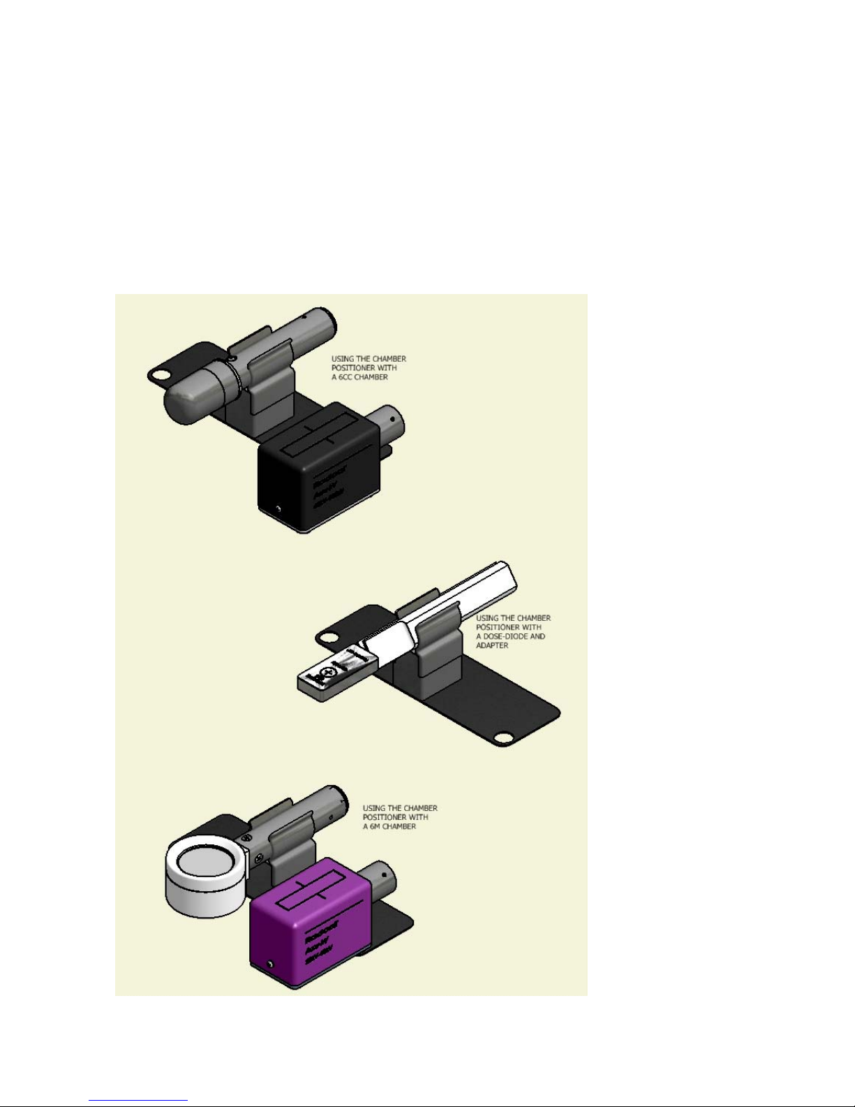
Chamber Positioner
The chamber positioner locates an ion chamber at a fixed height from the x-ray table. Holes in the base
of the chamber positioner locate the kV sensor relative to the ion chamber to control the effect of
backscatter from the kV sensor on exposure measurements. Because mammography measurements
using th 6M chamber are less affected by backscatter, the mammography kV sensor may be positioned
closer to the chamber. The Figure 29 shows suggested arrangements.
Figure 29 - Positioner/Chamber relationship
45

Accu-Pro™ System Carrying Cases
46

APPENDIX - Mammography kVp measurements on Hologic Selenia
Using a Radcal kVp Meter to Measure kVp's on Hologic Selenia Mammographic X-ray
Machine Equipped with a Tungsten-Rhodium, Silver Tube Option
A Radcal kV meter with a 40X series Mo sensor may be used with a look-up correction algorithm to
obtain Selenia W-Rh, Ag kVp's with an accuracy of +/- one kVp. Radcal recommends the Selenia
Tungsten-Ag/Rh tube be calibrated as follows.
After going into manual mode on the Hologic machine and selecting large focal spot,100mAs, place the
Radcal 40X9-Mo kV sensor on top of the Bucky table. The small compression paddle may be left
in-beam. Align the Radcal kV sensor so that its long axis is 90 degrees to the tube anode -cathode axis
so as to eliminate heel effect. Move the sensor about one inch in from the table edge. Center the sensor
right to left. Do not to forget to protect the imaging plate by placing and then smoothing out a lead apron
over it.
Use the Rhodium track to calibrate the 22 to 39 kV Selenia range and the Silver track to refine the 22 to
24 kV range to obtain a few more tenths accuracy if required from 22 to 24 kV. An example Selenia
calibration is shown below.
A Tungsten/Silver setting is different from the Tungsten/Rhodium setting. There is a range of calculated
kVp's (25-33 kV) that exceed a set error band and the instrument will show an error message as a result.
The data used to construct the correction algorithm were recorded by comparing a kVp's obtained with
Radcal Dynalyzer High Voltage Divider (True kVp) and the kVp's displayed on Radcal kVp meters during
Selenia exposures with the small compression paddle in-beam. These data were obtained from five
Selenia machines during Acceptance testing in manual mode.
Example of a Selenia calibration
Dynalyzer Ag Rh Ag Rh
Set kVp True kVp 9096 kVp 9096 kVp Radcal-True Radcal-True
22 22.0 22.5 22.5 0.5 0.5
23 23.0 23.0 23.5 0.0 0.5
24 24.0 24.2 25.0 0.2 1.0
25 25.0 25.6 0.6
26 26.0 26.1 0.1
27 27.0 27.3 0.3
28 28.0 28.1 0.1
29 29.0 29.3 0.3
30 30.0 30.1 0.1
31 31.0 30.9 -0.1
32 32.0 32.1 0.1
33 33.0 33.2 0.2
34 34.0 34.4 34.2 0.4 0.2
35 35.0 35.4 35.1 0.4 0.1
36 36.0 36.3 36.1 0.3 0.1
37 37.0 37.3 37.1 0.3 0.1
38 38.0 38.4 38.1 0.4 0.1
39 39.0 39.4 0.4
47

Warranty for the Accu-Pro™ Measurement System
Radcal Corporation warrants that, in the event that any defects in material or workmanship should
develop within one year of the date of shipment, the company assumes full responsibility for servicing
equipment of its manufacture without charge upon return of the equipment to Radcal, with shipping costs
prepaid by the customer. Costs to return-ship to customer by ground transportation will be paid by Radcal
if the repairs are warranty-applicable. This warranty excludes batteries.
Radcal shall not be held liable for damages or delays caused by defects beyond making repairs or
furnishing replacement parts, nor shall Radcal be liable for any defective material replaced without
Radcal’s consent during the period of this warranty. Radcal reserves the right to perform warranty
services at its own factory.
Non-Warranty Repairs
The calibration of this instrument was correct within specified limits when the instrument left our factory.
Radcal cannot be responsible for injury or damage resulting from improper use or calibration errors which
develop subsequent to our shipment of the instrument.
If Radcal determines that a fault has been caused by misuse, abnormal operating conditions, or repairs
by unauthorized personnel during the warranty period, repairs and shipping costs will be billed at normal
rates.
If the equipment is found to be in proper working condition, Radcal will return-ship the equipment at
customer expense.
48

Declaration of Conformity
According to ISO/IEC 17050 and EN 45014
The Radcal Corporation declares, under our sole responsibility, that the Accu-Pro™ Measurement
System conforms to the following product specifications.
EMC: EN 50081-2 / EN 555011 Class A
EN 50082-1 / IEC801-2, 4 kVcd, 8 kVAD
EN 50082-1 / IEC801-3, 3V/m
Note: The Analog Output is intended for use by trained users. Observe proper ESD precautions when
using this connection.
QA Manager
Date: 2007 September 27
Radcal Corporation
426 West Duarte Road
Monrovia, CA 91016-4591 USA
49
 Loading...