

rada Sense Shower T3 DMV Product Manual

1
IMPORTANT
Installer: This Manual is the property of the customer
and must be retained with the product for
maintenance and operational purposes.
PRODUCT MANUAL
Rada Sense Shower T3 DMV

2
CONTENTS
DESCRIPTION .......................................................................................... 3
SAFETY : WARNINGS .............................................................................3
PACK CONTENTS ....................................................................................5
SPECIFICATION ....................................................................................... 6
Standards and Approvals .....................................................................6
INSTALLATION .........................................................................................7
General .................................................................................................7
Power Supply Unit (PSU) .................................................................... 9
Rada Sense Control Panel ................................................................10
Rada Sense (DMV) ............................................................................ 11
OPERATION ...........................................................................................12
Duty Flush ..........................................................................................12
Disinfection ......................................................................................... 12
COMMISSIONING ..................................................................................13
Maximum Temperature Setting .......................................................... 14
MAINTENANCE ...................................................................................... 15
Planned Maintenance.........................................................................15
Cleaning ............................................................................................16
Checkvalves and Filters .....................................................................17
FAULT DIAGNOSIS ................................................................................ 18
Self-Diagnostic Errors ........................................................................20
SPARE PARTS .......................................................................................21
ACCESSORIES ......................................................................................23
CUSTOMER SERVICE ...........................................................................24

3
A range of concealed 1/2” Digital Mixing Valves (DMV) with wall mounted no-touch
control panel for ow and temperature control. Functions include timed ow control,
duty ush and thermal disinfection.
The sufx ‘3’indicates that this Digital Mixing Valve has been certied for use in UK
Healthcare premises as a Type 3 valve under the BuildCert TMV3 scheme. For
Healthcare installation refer to the TMV3 Requirements Manual.
The approved designations for Type 3 Valves are as follows:
Model Designations
Rada Sense Shower T3 HP - S LP - S
DESCRIPTION
SAFETY : WARNINGS
The function of this DMV is to deliver water consistently at a desired temperature.
This requires that:
1. It is installed, commissioned, operated and maintained in accordance with the
recommendations given in this manual.
2. Periodic attention is given, as necessary, to maintain the product in good
functional order. Recommended guidelines are given in ‘MAINTENANCE’.
3. For Type 3 installations, valves are only to be used for applications covered by
their approved designations. Refer to the TMV3 Requirements Manual.
4. Using this product outside the specication limits given in this manual can
present potential risk to users.
5. The electrical installation must comply with BS 7671 (commonly referred to
as the IEE Wiring Regulations), all relevant national building regulations and
any particular regulations and practices specied by the local electricity supply
company.
6. DO NOT t any form of outlet ow control i.e. trigger handset. Use only
recommended ttings.
The use of the word ‘failsafe’ to describe the function of any mixing valve is both
incorrect and misleading. This electronic valve incorporates additional shut-off
devices to improve the level of safety however, in keeping with every other mechanism
it cannot be considered as being functionally infallible.

4
Where chlorine disinfection is practised, DO NOT exceed a chlorine concentration of
50 mg/l (ppm) in water, per one hour dwell time. Such procedures must be conducted
strictly in accordance with the information supplied with the disinfectant and with all
relevant Guidelines/Approved Codes of Practice.
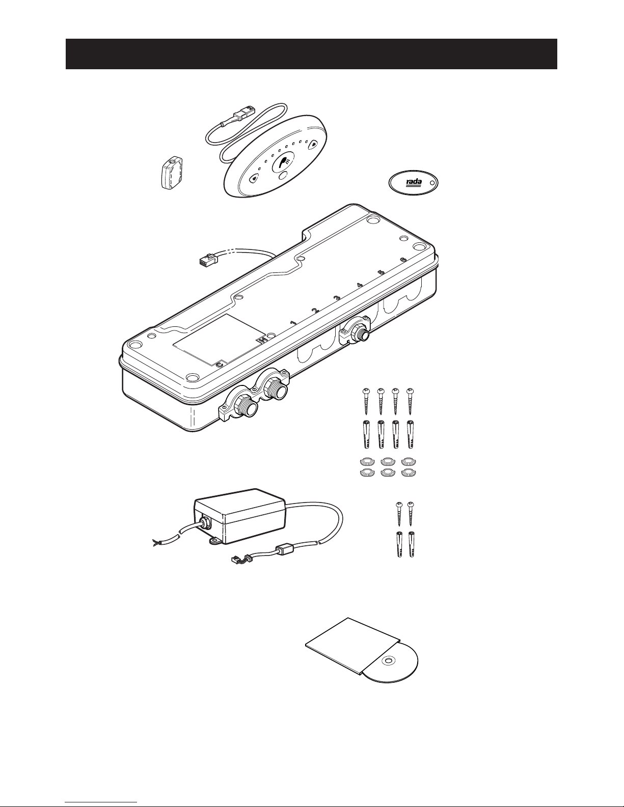
5
PACK CONTENTS
1 x Shower Control Panel
1 x Magnetic Key
1 x Digital Mixing Valve (DMV)
4 x Fixing Screws
4 x Wall Plugs
1 x Power Supply Unit (PSU)
2 x Fixing Screws
2 x Wall Plugs
2 x Installation Templates
(DMV Installation Template, on the Packaging)
6 x Rubber Feet
1 x UK Rada Sense T3 Programmer CD
1 x Suppression Ferrite
1 x TMV3 Requirements Manual

6
Standards and Approvals
This Rada Sense Digital Mixing Valve (DMV) complies with all relevant directives
for CE marking.
The Rada Sense DMV is a type 1 electronic, independently mounted control for
surface mounting.
For Type 3 valves, the water supply conditions are specified in the TMV3
Requirements Manual.
General
Pollution Degree 3
Rated Impulse Voltage Mains Supply - 2.5 kV
12 V DC supply to valve - 500 V
Suitability for Drinking Not suitable
Connections Flat face union connections
Pressures
Maximum Static Pressure 1000 kPa (10 bar)
Minimum Pressure Loss 20 kPa (0.2 bar)
Supply Pressure Differential Max. 3:1 (Equal pressure recommended)
Minimum Flow Rate 4 L/min (<500 kPa maintained pressure)
6 L/min (>500 kPa maintained pressure)
Temperatures
Factory Pre-set (Blend) Washbasin Max. 41 °C, Min. 30 °C, Default at start-up 38 °C
Factory Pre-set (Blend) Bidet Max. 38 °C, Min. 30 °C, Default at start-up 36 °C
Factory Pre-set Duty Flush 41 °C (Default DISABLED - use Programmer Software to ENABLE)
Programmable Range Max. 33 - 50 °C
Min. 30 - 47 °C (full cold can also be selected)
Default at start-up 30 - 50 °C
Minimum Blend Temperature
Differential from Hot Supply
2 °C
Optimum Thermostatic
Control Range
30 - 50 °C
Cold Water Range 1 - 20 °C
Hot Water Range 50 - 65 °C (85 °C for disinfection)
Temperature Stability ± 1 °C at recommended supply conditions
Ambient Temperature Greater than 1 °C, max. 40 °C
Maximum Relative Humidity 95% non-condensing
Electrical
Supply Voltage 100 - 240 V RMS 50 - 60 Hz
Maximum Load 20 W at 12 V DC
Control Panel Cable Length 3 m supplied (6 m max.)
Times Factory Settings Programmable Range
Flow Time to Auto Shut-off 15 seconds 5 seconds to 60 minutes
Duty Flush Cycle 3 minutes 1 - 59 minutes
Duty Flush Waiting Time 12 hours 1 - 983 hours
Disinfection
Minimum Temperature 60 °C 60 - 85 °C
Minimum Time 5 minutes 0 - 50 minutes
Reduced Flow rate No Yes or No
The pressure loss of a system (valve and outlet tting) is the average of the two inlet pressures minus the back
pressure, where the back pressure is determined by the ow resistance of any outlet tting.
SPECIFICATION
*
*

7
General
Installation must be carried out in accordance with these instructions, be
conducted by designated, qualied and competent personnel.
The installation must comply with the “Water Supply (Water Fittings)
Regulations or Scottish Byelaws”, all relevant national building regulations
and any particular regulations and practices specied by the local water
supply company.
Before commencing, make sure that the installation conditions comply with the
information given in ‘SPECIFICATION’. For Type 3 valves, the water supply
conditions must comply with the information given in the TMV3 Requirements
Manual.
Installation Schematic
Note! The Data Cable must be placed through the Suppression Ferrite and then
looped around the cover. The Suppression Ferrite must be tted as close to the
Control Panel as possible.
INSTALLATION
Metal pipework
must be
earth bonded
3 amp switched
fused spur box
Control panel
PSU
DMV
Showerhead
Outlet
Hot
inlet
Cold
inlet
To mains power supply
Suppression Ferrite,
refer to Note.
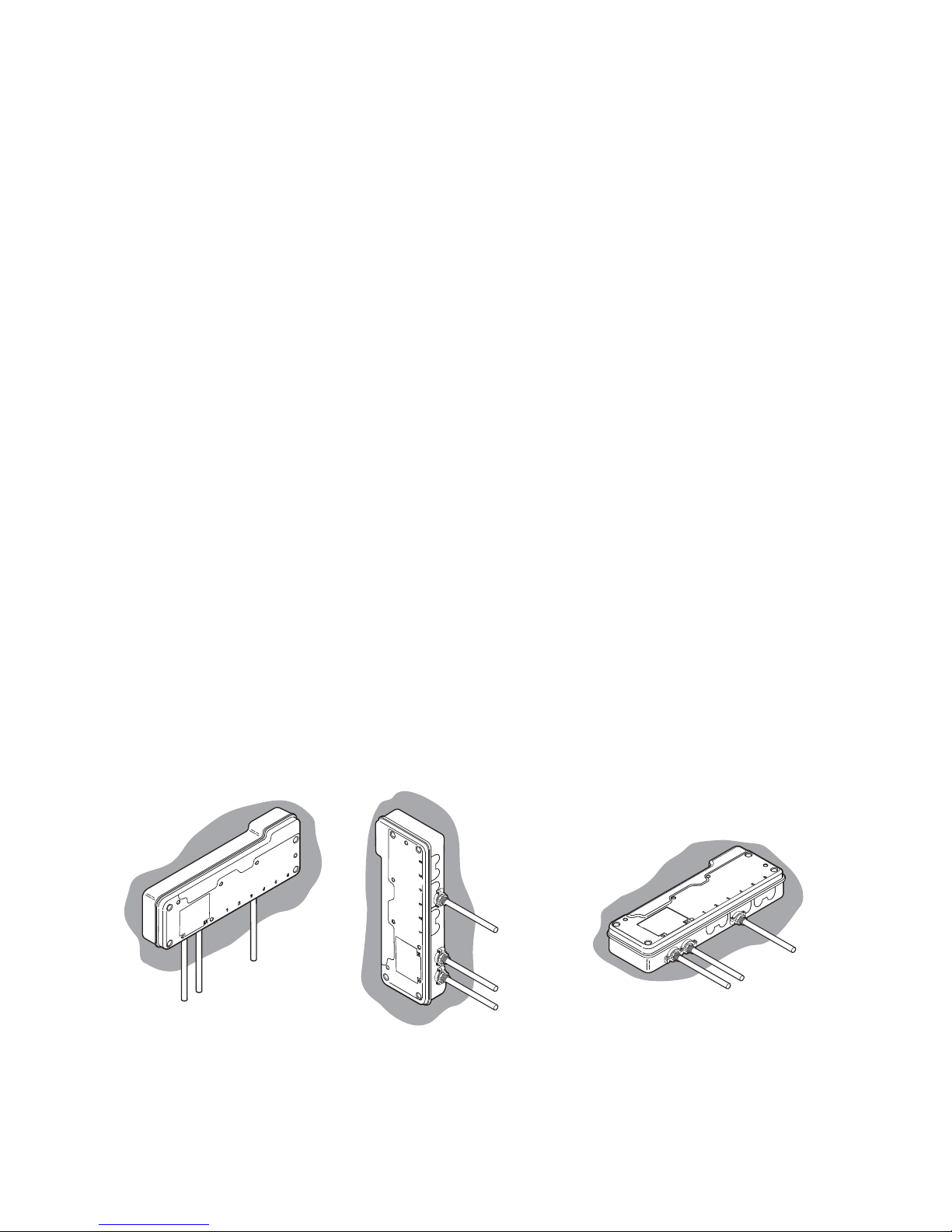
8
Outlet
Hot inlet
Cold inlet
Outlet
Hot inlet
Cold inlet
Outlet
Hot inlet
Cold inlet
Mounting on a
Vertical Surface
Mounting on a
Horizontal Surface
1. The DMV and PSU must be installed in a dry area and where it will not freeze.
2. The DMV must be installed in an area where it is accessible to do any
maintenance tasks e.g. removal of the cover, cleaning the strainers, etc.
3. Inlet and outlet isolating valves must be installed close to the DMV for ease of
maintenance.
4. Flat face union connections must be used on the inlet and outlet connections
of the DMV for ease of maintenance.
5. The use of supply-line or zone strainers will reduce the need to remove debris at
each mixing valve point. The recommended maximum mesh aperture dimension
for such strainers is 0.5 mm.
6. Inlet pressure tappings which allow measurement of the inlet pressures to
the mixing valve under operating conditions are particularly recommended for
healthcare applications.
7. Pipework must be rigidly supported and avoid any strain on the connections.
8. Pipework dead-legs should be kept to a minimum.
9. Supply pipework layout should be arranged to minimise the effect of other outlet
usage upon the dynamic pressures at the mixing valve inlets.
10. Inlet and outlet threaded joint connections should be made with PTFE tape or
liquid sealant. Do not use oil-based, non-setting joint compounds.
11. To eliminate pipe debris it is essential that supply pipes are thoroughly ushed
through before connection to the spout and to the Rada Sense DMV.
12. The DMV MUST be installed in the orientations shown and mounted on a rigid
vertical surface or on top of a rigid horizontal surface.
Note! If the DMV is installed in a different orientation to those shown above, it may
cause the DMV to malfunction e.g. cause airlocks, water ingress and could effect
the thermal performance of the DMV.
 Loading...