

Page 1
User manual
www.racom.eu
RACOMs.r.o. •Mirova1283•59231NoveMestonaMorave•CzechRepublic
Tel.:+420565659511•Fax:+420565659512•E-mail: racom@racom.eu
.
RipEX
Radio modem & Router
.
version 1.4
10/26/2012
fw 1.2.x.x
Page 2

Page 3

Table of Contents
Getting started ..................................................................................................................................... 7
1. RipEX – Radio router ...................................................................................................................... 9
1.1. Introduction ........................................................................................................................... 9
1.2. Key Features ........................................................................................................................ 9
1.3. Standards ........................................................................................................................... 10
2. RipEX in detail ............................................................................................................................... 12
2.1. Modes of operation ............................................................................................................. 12
2.2. Bridge mode ....................................................................................................................... 12
2.3. Router mode ....................................................................................................................... 17
2.4. Serial SCADA protocols ..................................................................................................... 22
2.5. Combination of IP and serial communication ..................................................................... 23
2.6. Diagnostics & network management .................................................................................. 23
2.7. Firmware update and upgrade ........................................................................................... 25
2.8. Software feature keys ......................................................................................................... 26
3. Network planning ........................................................................................................................... 27
3.1. Data throughput, response time ......................................................................................... 27
3.2. Frequency .......................................................................................................................... 28
3.3. Signal budget ..................................................................................................................... 29
3.4. Multipath propagation, DQ ................................................................................................. 31
3.5. Network layout .................................................................................................................... 33
3.6. Hybrid networks .................................................................................................................. 35
3.7. Assorted practical comments ............................................................................................. 35
3.8. Recommended values ........................................................................................................ 36
4. Product .......................................................................................................................................... 38
4.1. Dimensions ......................................................................................................................... 38
4.2. Connectors ......................................................................................................................... 39
4.3. Indication LEDs .................................................................................................................. 44
4.4. Technical specification ........................................................................................................ 45
4.5. Model offerings ................................................................................................................... 53
4.6. Accessories ........................................................................................................................ 55
5. Bench test ..................................................................................................................................... 60
5.1. Connecting the hardware ................................................................................................... 60
5.2. Powering up your RipEX .................................................................................................... 60
5.3. Connecting RipEX to a programming PC ........................................................................... 60
5.4. Basic setup ......................................................................................................................... 64
5.5. Functional test .................................................................................................................... 64
6. Installation ..................................................................................................................................... 65
6.1. Mounting ............................................................................................................................. 65
6.2. Antenna mounting .............................................................................................................. 68
6.3. Antenna feed line ............................................................................................................... 68
6.4. Grounding ........................................................................................................................... 69
6.5. Connectors ......................................................................................................................... 69
6.6. Power supply ...................................................................................................................... 69
7. Advanced Configuration ................................................................................................................ 70
7.1. Menu header ...................................................................................................................... 70
7.2. Status ................................................................................................................................. 71
7.3. Settings ............................................................................................................................... 72
7.4. Routing ............................................................................................................................. 104
7.5. Diagnostic ......................................................................................................................... 106
7.6. Maintenance ..................................................................................................................... 120
8. CLI Configuration ........................................................................................................................ 123
3© RACOM s.r.o. – RipEX Radio modem & Router
Page 4

RipEX
Radio modem & Router
9. Troubleshooting ........................................................................................................................... 124
10. Safety, environment, licensing ................................................................................................... 126
10.1. Frequency ...................................................................................................................... 126
10.2. Safety distance ............................................................................................................... 126
10.3. High temperature ............................................................................................................ 130
10.4. RoHS and WEEE compliance ........................................................................................ 130
10.5. Conditions of Liability for Defects and Instructions for Safe Operation of Equipment .... 130
10.6. Important Notifications .................................................................................................... 131
10.7. Product Conformity ......................................................................................................... 132
A. OID mappings ............................................................................................................................. 133
B. Abbreviations .............................................................................................................................. 153
Index ................................................................................................................................................ 155
C. Revision History .......................................................................................................................... 157
List of Figures
1. RipEX radio router ........................................................................................................................... 7
2.1. Bridge mode example ................................................................................................................ 15
2.2. Addressing ................................................................................................................................. 20
2.3. Optimised addressing ................................................................................................................. 21
2.4. Monitoring ................................................................................................................................... 25
3.1. Application bench test ................................................................................................................ 28
3.2. Signal path ................................................................................................................................. 29
3.3. Multipath propagation ................................................................................................................. 31
3.4. Antenna location ......................................................................................................................... 32
3.5. Main lobe .................................................................................................................................... 33
3.6. Dominant repeater ...................................................................................................................... 34
3.7. Isolated branches ....................................................................................................................... 34
3.8. Antenna mounting ...................................................................................................................... 36
4.1. RipEX dimensions, see more ..................................................................................................... 38
4.2. L-bracket and Flat-bracket, see more ........................................................................................ 38
4.3. Connectors ................................................................................................................................. 39
4.4. Antenna connector TNC ............................................................................................................. 39
4.5. Separated Rx and TX antennas ................................................................................................. 40
4.6. Supply connector ........................................................................................................................ 41
4.7. Power and Control - cable plug .................................................................................................. 41
4.8. RJ-45F ........................................................................................................................................ 42
4.9. Serial connector ......................................................................................................................... 42
4.10. Serial connector ....................................................................................................................... 43
4.11. Reset ........................................................................................................................................ 43
4.12. GPS Connector SMA ............................................................................................................... 43
4.13. Indication LEDs ........................................................................................................................ 44
4.14. RipEX-HS ................................................................................................................................. 55
4.15. X5 adapter ETH/USB ............................................................................................................... 55
4.16. Demo case ............................................................................................................................... 56
4.17. Assembly dimensions with fan ................................................................................................. 57
4.18. L-bracket .................................................................................................................................. 57
4.19. Flat bracket ............................................................................................................................... 57
4.20. 19" Rack shelf .......................................................................................................................... 58
4.21. 19" Rack shelf – double ........................................................................................................... 58
4.22. Dummy load ............................................................................................................................. 58
5.1. Bench test .................................................................................................................................. 60
RipEX Radio modem & Router – © RACOM s.r.o.4
Page 5

RipEX
Radio modem & Router
5.2. Connecting to a PC over ETH and over ETH/USB adapter ....................................................... 61
5.3. PC address setting ..................................................................................................................... 62
5.4. Authentication ............................................................................................................................. 63
5.5. Status Menu ............................................................................................................................... 63
6.1. Flat lengthwise mounting to DIN rail – recommended ............................................................... 65
6.2. Flat widthwise mounting to DIN rail ............................................................................................ 65
6.3. Vertical widthwise mounting to DIN rail ...................................................................................... 66
6.4. Vertical lengthwise mounting to DIN rail ..................................................................................... 66
6.5. Flat mounting using Flat bracket ................................................................................................ 66
6.6. Rack shelf ................................................................................................................................... 67
6.7. Fan kit mounting ......................................................................................................................... 67
6.8. Fan kit using Alarm Output, recommended ................................................................................ 68
6.9. Fan kit, always on ....................................................................................................................... 68
6.10. 10–30 VDC Supplying .............................................................................................................. 69
7.1. Menu Header .............................................................................................................................. 70
7.2. Menu Status ............................................................................................................................... 71
7.3. Menu Settings ............................................................................................................................ 72
7.4. Menu Alarm management .......................................................................................................... 78
7.5. Menu Radio ................................................................................................................................ 82
7.6. Menu Ethernet ............................................................................................................................ 85
7.7. Menu COM ................................................................................................................................. 90
7.8. Menu Protocols COM ................................................................................................................. 92
7.9. Menu Routing ........................................................................................................................... 104
7.10. Menu Neighbours ................................................................................................................... 106
7.11. Menu Statistic ......................................................................................................................... 109
7.12. Menu Graphs .......................................................................................................................... 110
7.13. Menu Ping .............................................................................................................................. 112
7.14. Menu Monitoring ..................................................................................................................... 115
7.15. Monitoring ............................................................................................................................... 119
7.16. Menu SW feature keys ........................................................................................................... 120
7.17. Menu Maintenance Configuration .......................................................................................... 121
7.18. Menu Maintenance Firmware ................................................................................................. 121
7.19. Menu Maintenance Password ................................................................................................ 122
7.20. Menu Maintenance Configuration .......................................................................................... 122
List of Tables
4.1. Pin assignement ......................................................................................................................... 40
4.2. Ethernet to cable connector connections ................................................................................... 42
4.3. COM1,2 pin description .............................................................................................................. 42
4.4. USB pin description .................................................................................................................... 43
4.5. Key to LEDs ............................................................................................................................... 44
4.6. Technical parameters ................................................................................................................. 45
4.7. Recommended Cables ............................................................................................................... 48
4.8. CE 25 kHz .................................................................................................................................. 49
4.9. CE 12.5 kHz ............................................................................................................................... 50
4.10. CE 6.25 kHz ............................................................................................................................. 50
4.11. FCC 25 kHz .............................................................................................................................. 51
4.12. FCC 12.5 kHz ........................................................................................................................... 51
4.13. FCC 6.25 kHz ........................................................................................................................... 51
10.1. Minimum Safety Distance 160 MHz ....................................................................................... 126
10.2. Minimum Safety Distance 300–400 MHz ............................................................................... 128
5© RACOM s.r.o. – RipEX Radio modem & Router
Page 6

6
Page 7
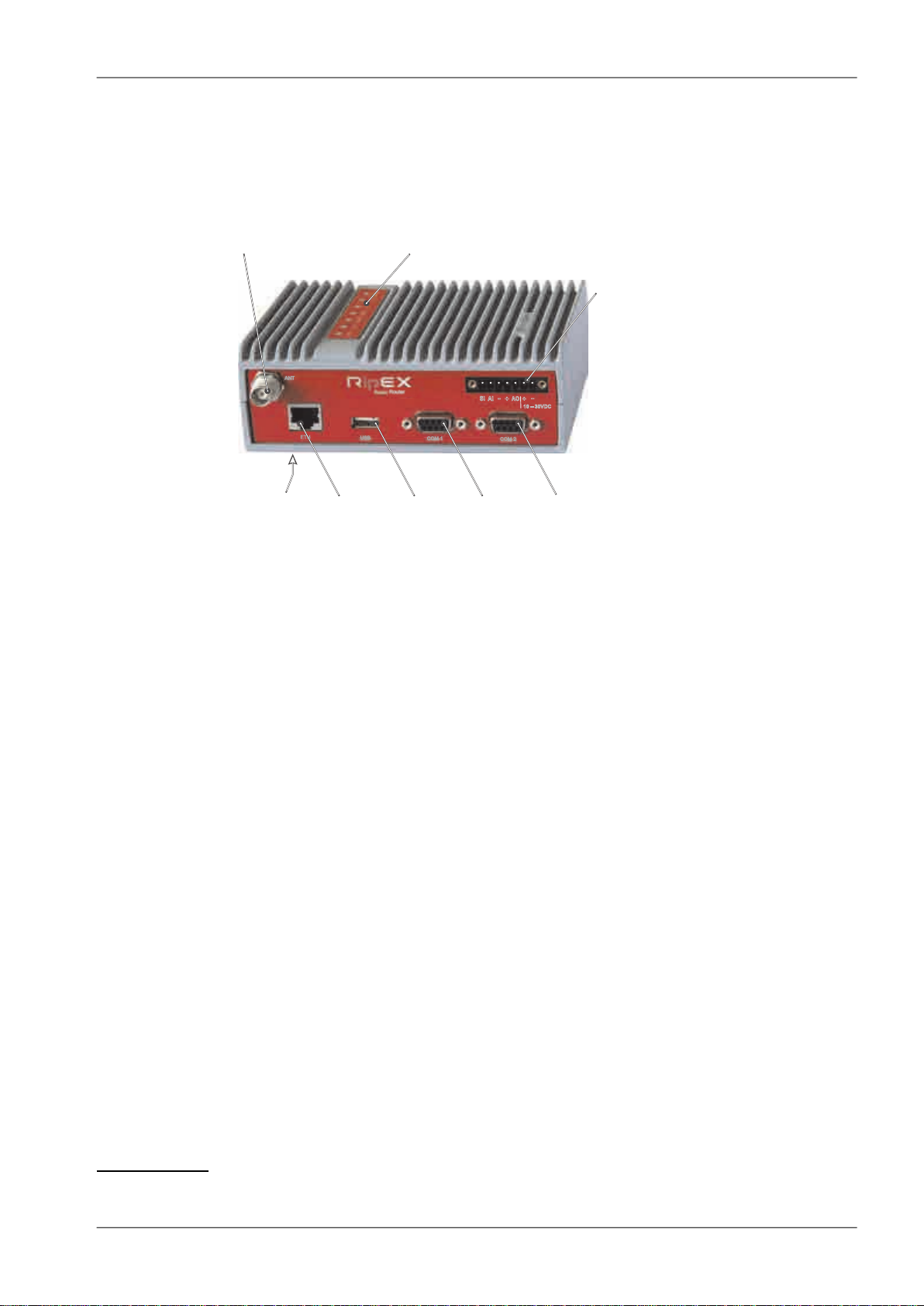
Antenna
IndicatorLEDs'
SleepInput
HW AlarmInput
-GND
+
HW AlarmOutput
Supply+10to+30V
-GND
Ethernet
USB
COM1
RS232
COM2
RS232/485
Default/Reset
-
-
+
+
SI
AI
AO
10–30VDC
ETH
USB
ANT
COM1
COM2
Getting started
Getting started
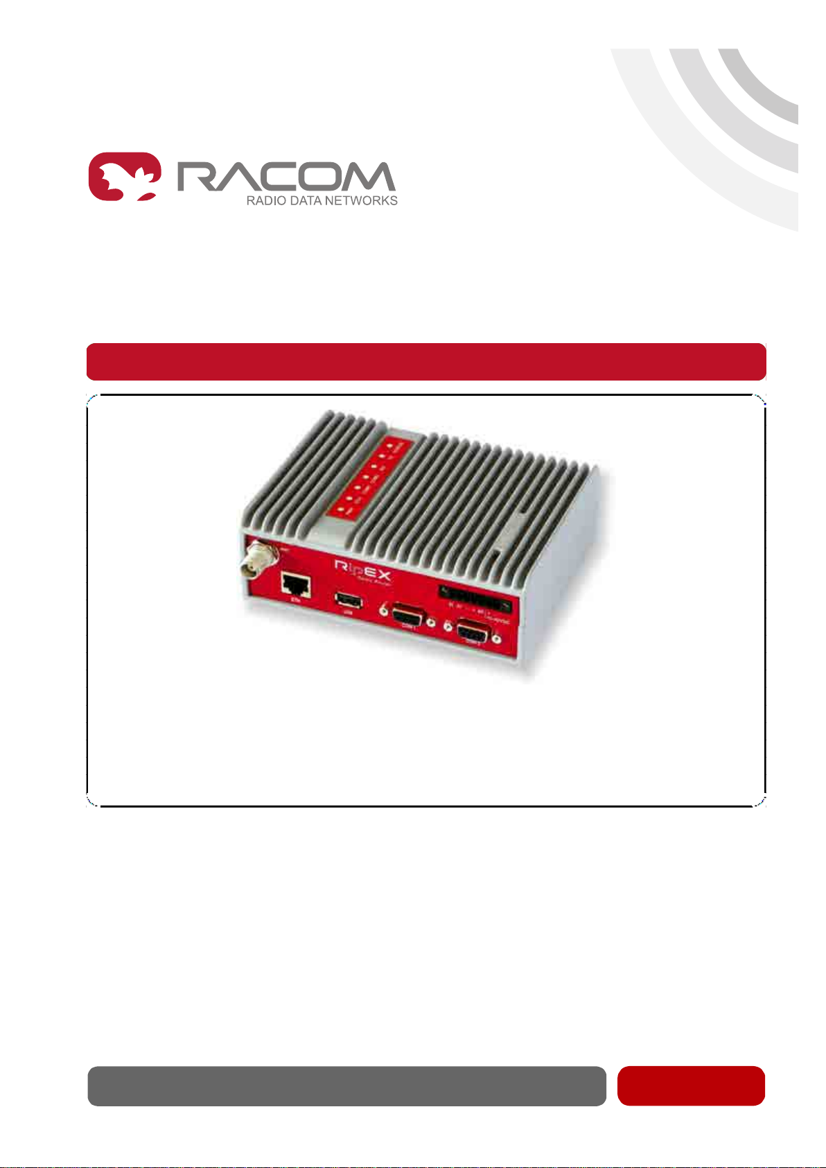
RipEX is a widely configurable compact radio modem, more precisely a radio IP router. All you have
to do to put it into operation is to connect it to an antenna and a power supply and configure it using a
PC and a web browser.
Fig. 1: RipEX radio router
RipEX access defaults: IP 192.168.169.169/24, username: admin, password: admin
Set a static IP 192.168.169.x/24 on your PC, power on the RipEX and wait approximately 25 seconds
for the RipEX OS to boot. Connect your PC to RipEXs' ETH interface, start your browser and type https://192.168.169.169 in the address line. When accessing RipEX for the first time, you have to accept
the https security certificate issued by Racom.
Before attempting to do any configuration, make sure your RipEX is the only powered-up unit around.
Since all units coming from factory share the same default settings ex factory, you could be accessing
a different unit over the air without being aware of it.
When accessing over the optional “X5” USB/ETH adapter, your PC will get its IP settings from the builtin DHCP server and you have to type https://10.9.8.7 in your browser. Remaining steps are the same
and you do not need to worry about other RipEX's, you will be connected to the local unit in all cases.
SCADA radio network step-by-step
Building a reliable radio network for a SCADA system may not be that simple, even when you use such
a versatile and easy-to-operate device as the RipEX radio modem. The following step-by-step checklist
can help you to keep this process fast and efficient.
1. Design your network to ensure RF signal levels meet system requirements.
2. Calculate and estimate the network throughput and response times when loaded by your application.
3.
Perform a bench-test with 3-5 sets of RipEX's and SCADA equipment (Chapter 5, Bench test).
4.
Design the addressing and routing scheme of the network (Chapter 2, RipEX in detail and RipEX
App notes, Address planing1)
5. Preconfigure all RipEX's (Section 5.4, “Basic setup”).
6. Install individual sites
1. Mount RipEX into cabinet (Section 6.1, “Mounting”).
1
http://www.racom.eu/eng/products/m/ripex/app/routing.html
7© RACOM s.r.o. – RipEX Radio modem & Router
Page 8

Getting started
2. Install antenna (Section 6.2, “Antenna mounting”).
3. Install feed line (Section 6.3, “Antenna feed line”).
4. Ensure proper grounding (Section 6.4, “Grounding”).
5. Run cables and plug-in all connectors except from the SCADA equipment (Section 4.2,
“Connectors”)
6. Apply power supply to RipEX
7. Test radio link quality (Section 5.5, “Functional test”).
8. Check routing by the ping tool (the section called “Ping”) to verify accessibility of all IP addresses with which the unit will communicate.
9. Connect the SCADA equipment
7. Test your application
RipEX Radio modem & Router – © RACOM s.r.o.8
Page 9

RipEX – Radio router
1. RipEX – Radio router
1.1. Introduction
RipEX is a best-in-class radio modem, not only in terms of data transfer speed. This Software Defined
Radio with Linux OS has been designed with attention to detail, performance and quality. All relevant
state-of-the-art concepts have been carefully implemented.
RipEX provides 24×7 reliable service for mission-critical applications like SCADA & Telemetry for Utilities, SmartGrid power networks or transaction networks connecting lottery terminals, POS or ATM’s.
Any unit can serve as the central master, repeater, remote terminal, or all of these simultaneously, with
a configuration interface easily accessible from a web browser.
Anybody with even basic knowledge of IP networking can set up a RipEX within a matter of minutes
and maintain the network quite easily.
1.2. Key Features
• Exceptional data speeds on the radio channel
- 83 kbps / 25 kHz, 42 kbps / 12.5 kHz, 21 kbps / 6.25 kHz
• 1× ETH, 2× COM, 1× USB, 5× virtual COM
- Simultaneously on radio channel. COM1-RS232, COM2-RS232 or RS485, software configurable.
Virtual COMs over ETH controlled by Terminal servers. USB for independent service access via
USB/ETH adapter.
• 135–175; 300–360; 368–470; 928–960 MHz
- Licensed radio bands
- Software-selectable channel spacing 25, 12.5 or 6.25 kHz
• 10 watts
- Transmission output control, nine stages from 0.1 to 10 W (max. 2 W for linear modulations).
• Energy saving
- Sleep mode – 0.1 W, controlled via a digital input.
- Save mode – 2.3 W, wake up by receiving a packet from the radio channel
• Extended temperature range
−40 to +70 ºC
• Easy to configure and maintain
- Web interface,
- Wizards,
- On-line help,
- Balloon tips,
- Fastest web access to remote units
• Bridge or Router
- RipEX is a device with native IP support which can be set as a standard bridge or router.
9© RACOM s.r.o. – RipEX Radio modem & Router
Page 10

RipEX – Radio router
• Modbus, IEC101, DNP3, Comli, RP570, C24, DF1, Profibus, Modbus TCP, IEC104, DNP3 TCP
etc.
- Unique implementation of industrial protocols enables a secure addressed transmission of all
packets in all directions
• Anti-collision protocol on radio channel
- Allows multi polling & report-by-exception concurrently for several independent applications simultaneously
• Optimization – 3× higher throughput
- Optimization method which joins short packets, compresses data, optimises both the traffic to the
link peer and the sharing of the radio channel capacity among the links.
• Embedded diagnostic & NMS
- Real time and historical (20 periods, e.g. days) statistics and graphs for the unit and its neighbours.
- SNMP including generation of TRAP alarms when preset thresholds are exceeded
- on-line/off-line (recorded to a file in the RipEX) monitoring of all interfaces
• 256 AES encryption
- The most secure encryption meets FIPS 140 2 requirements
• Pay only for what you need
- Software authorization keys allow you to add advanced features when needed (Router mode, 83
kbps, COM2, 10 W)
- Free Master-key trial – (all coded features) for 30 days in every RipEX
• Reliability
- 3 years warranty, rugged die cast aluminium case, military or industrial components
- Every single unit tested in a climatic chamber as well as in real traffic
• RipEX - HS
- Redundant hot standby chassis
- Two hot-stand-by standard RipEX units inside
- Automatic switchover capability on detection of failure
- Suitable for Central sites, Repeaters or Important remote sites where no single point of failure is
required
• Internal calendar time
- Can be set manually or synchronized via NTP (Network Time Protocol)
- Any RipEX also runs as a NTP server automatically
- NTP synchronization via Ethernet or over the Radio channel from another RipEX
- Powered from internal long life Lithium Manganese battery, so it is accurate even when RipEX is
powered off
• Flash memory
- All configuration parameters are saved in flash memory
- Configuration and other parameters are safely saved even when RipEX is powered off
1.3. Standards
ETSI EN 300 113-2 V1.5.1Spectrum (art 3.2)
FCC Part 90
ETSI EN 301 489-1 V1.9.2EMC (art 3.1.b)
RipEX Radio modem & Router – © RACOM s.r.o.10
Page 11

ETSI EN 301 489-5 V1.3.1
EN 60950-1:2006Electrical Safety (art 3.1.a)
EN 60950–1:2006/A11:2009,
EN 60950–1:2006/A12:2011,
EN 60950–1:2006/A1:2010
IP40IP rating
IEEE 802.3iETH
IEEE 802.3u
IEEE 802.3af
EIA-232-FRS232
EIA RS-485RS485
IEC 60870-5-101IEC101
IEC 60870-5-104IEC104
RipEX – Radio router
IEEE 1815-2010DNP3
IEC 61158 Type 3Profibus DP
11© RACOM s.r.o. – RipEX Radio modem & Router
Page 12

RipEX in detail
2. RipEX in detail
2.1. Modes of operation
Radio modem RipEX is best suited for transmission of a large number of short messages where a
guaranteed delivery time is required, i.e. for mission critical applications.
RipEX has the following basic uses:
• Polling
In poll-response networks a central master unit communicates with a number of remote radiomodems
one at a time. The master unit exchanges data with the currently connected remote radio, and when
finished, it establishes a new connection with the next remote radio according to the polling order.
• Report-by-exception
In report-by-exception networks remote units can be contacted similarly to polling networks. In addition, any remote unit can spontaneously send data to the master unit (typically an alarm).
• Mesh
In mesh type networks any radio modem in the network can access any other radio modem randomly
and spontaneously. Mesh network can also host polling or report-by-exception applications, even
in several instances.
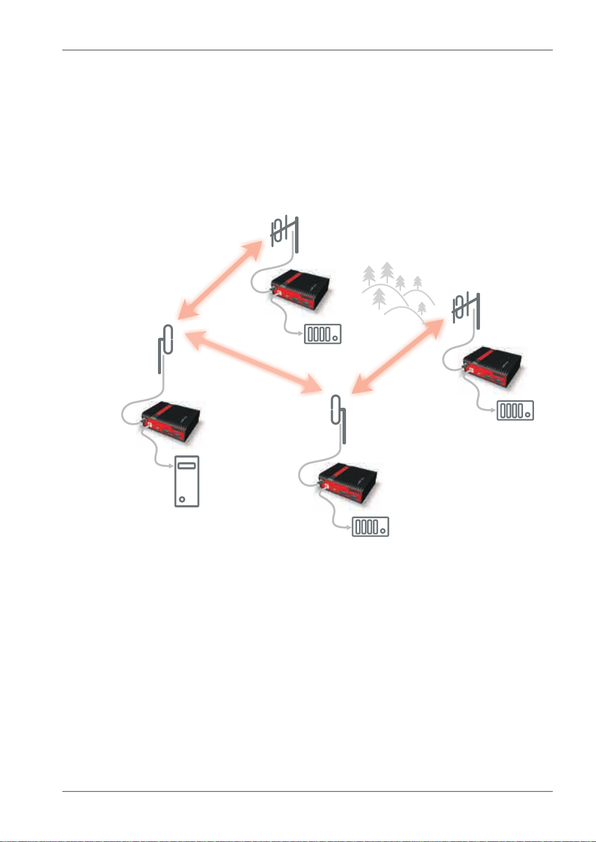
2.2. Bridge mode
A packet received through any interface is broadcast to the appropriate interfaces of all units within the
network. Packets received on COM are broadcast to both COM1 and COM2 at remote sites, allowing
you to connect 2 RTU's to any radio modem.
Any unit can be configured as a repeater. A repeater relays all packets it receives through the radio
channel. The network implements safety mechanisms which prevent cyclic loops in the radio channel
(e.g. when a repeater receives a packet from another repeater) or duplicate packets delivered to the
user interface (e.g. when RipEX receives a packet directly and then from a repeater).
Beside standard packet termination by an "Idle" period on the serial port (a pause between received
bytes) the bridge mode also offers "streaming". While in streaming mode, transmission on the radio
channel starts immediately, without waiting for the end of the received frame on COM => zero latency.
The bridge mode is suitable for all polling applications.
2.2.1. Detailed Description
Bridge mode is suitable for Point-to-Multipoint networks, where Master-Slave applications with pollingtype communication protocol are used. RipEX in bridge mode is as easy to use as a simple transparent
device, while providing communication reliability and spectrum efficiency by employing a sophisticated
protocol in the radio channel.
In bridge mode, the radio channel protocol do not solve collisions. There is a CRC check of data integrity,
however, i.e. once a message is delivered, it is 100% error free.
RipEX Radio modem & Router – © RACOM s.r.o.12
Page 13
RipEX in detail
All the messages received from user interfaces (ETH&COM's) are immediately transmitted to the radio
channel.
ETH - The whole network of RipEX radiomodems behaves as a standard ethernet network bridge.
Each ETH interface automatically learns which devices (MAC addresses) are located in the local LAN
and which devices are accessible over the radio channel. Consequently, only the ethernet frames addressed to remote devices are physically transmitted on the radio channel. This arrangement saves
the precious RF spectrum from extra load which would be otherwise generated by local traffic in the
LAN (the LAN to which the respective ETH interface is connected).
COM1,COM2 - All frames received from COM1(2) are broadcast over the radio channel and transmitted
to all COM's (COM1 as well as COM2) on all radio modems within the network, the other COM on the
source RipEX excluding.
There is a special parameter TX delay (Adv. Config., Device), which should be used when all substations
(RTU's) reply to a broadcast query from the master station. In such case massive collisions would ensue
because all substations (RTU's) would reply at nearly the same time. To prevent such collision, TX
delay should be set individually in each slave RipEX. The length of responding frame, the length of
radio protocol overhead, modulation rate have to be taken into account.
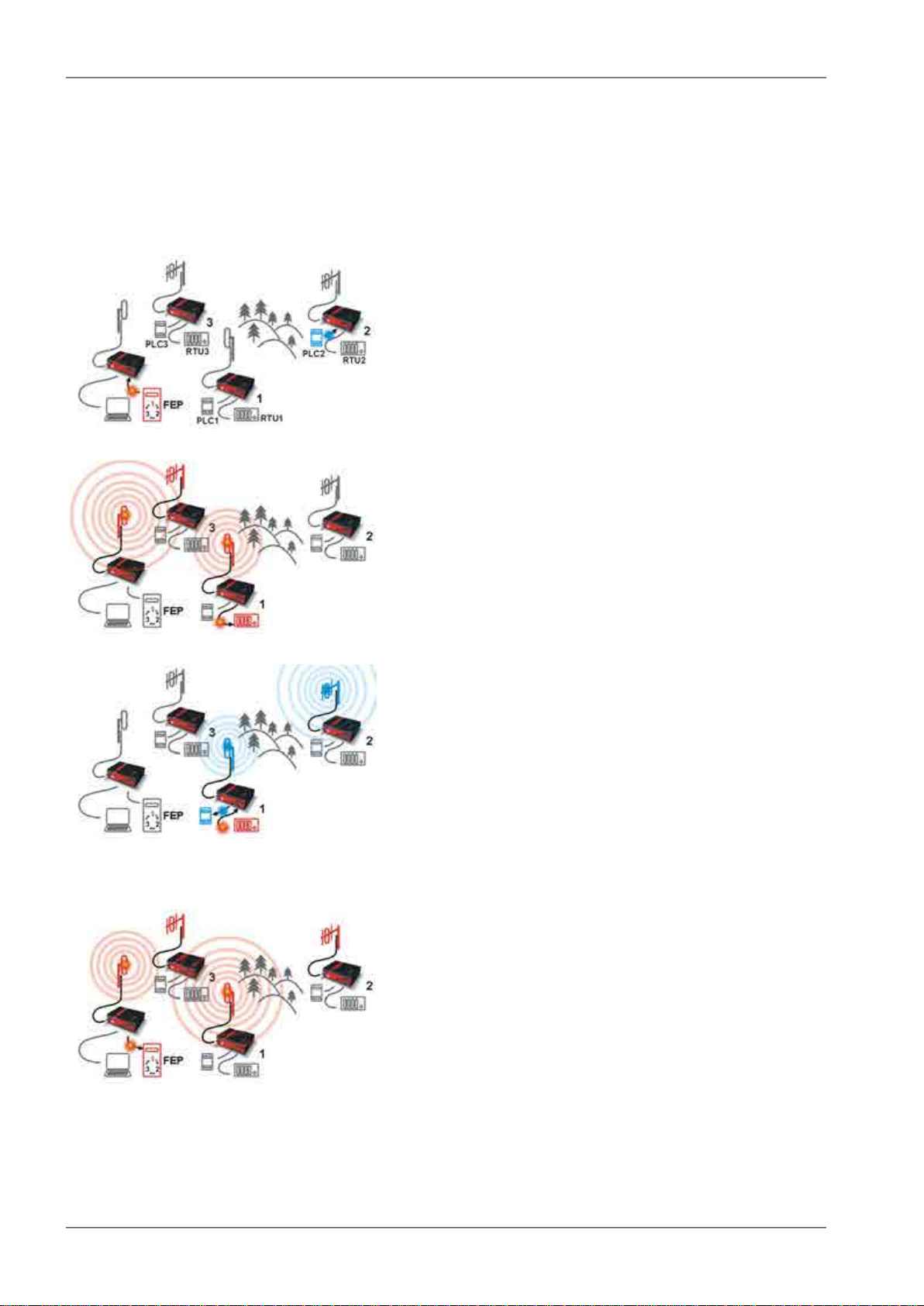
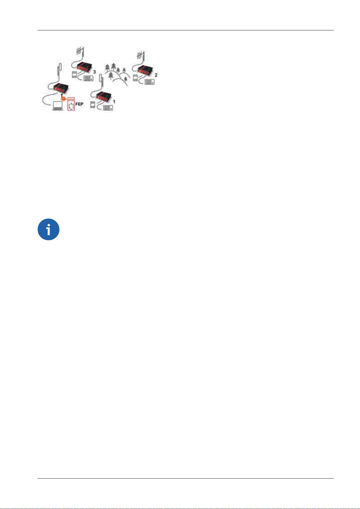
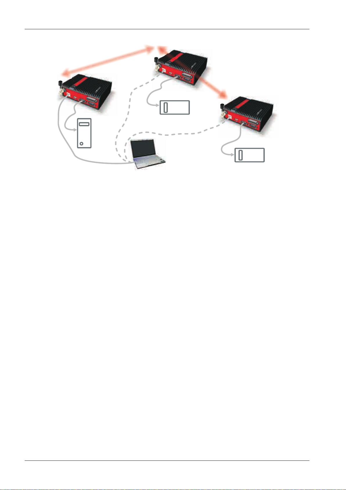
2.2.2. Functionality example
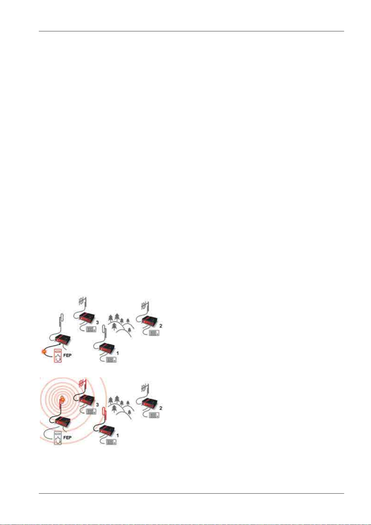
In the following, common acronyms from SCADA systems are used:
• FEP - Front End Processor, designates the communication interface equipment in the centre
• RTU - Remote Telemetry Unit, the terminal SCADA equipment at remote sites
The single digits in illustrations are “site names” and do not necessarily correspond with actual addresses
of both the RipEX's and SCADA equipment. Address configuration examples are given in the next
chapter.
Step 1
Polling cycle starts:
FEP sends a request packet for RTU3 through COM1 to
the connected RipEX.
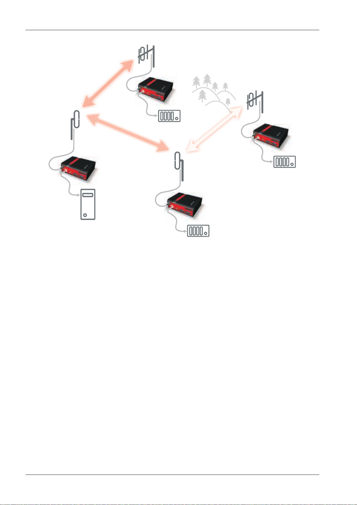
Step 2
FEP’s RipEX broadcasts this packet on Radio channel.
RipEX3 and RipEX1 receive this packet.
RipEX2 doesn’t receive this packet, because it is not within
radio coverage of FEP’s RipEX.
13© RACOM s.r.o. – RipEX Radio modem & Router
Page 14
RipEX in detail
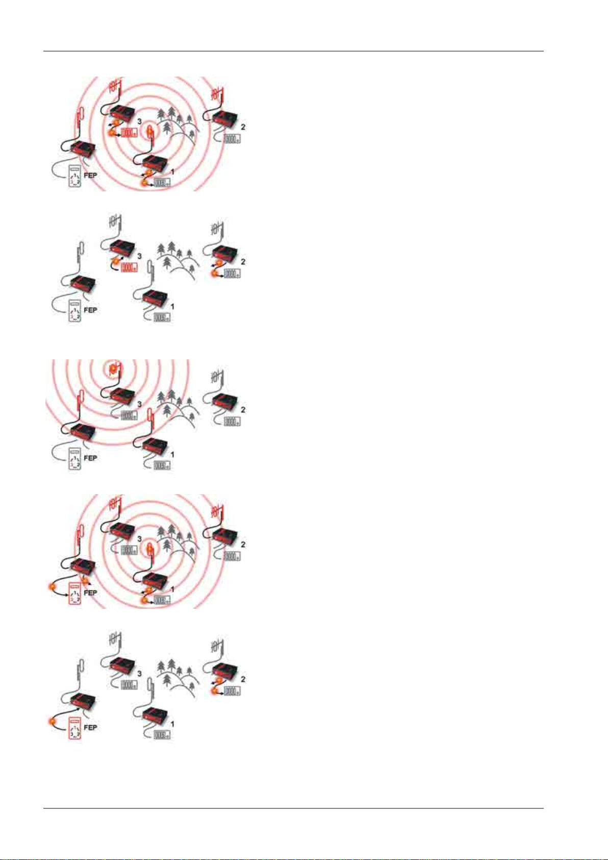
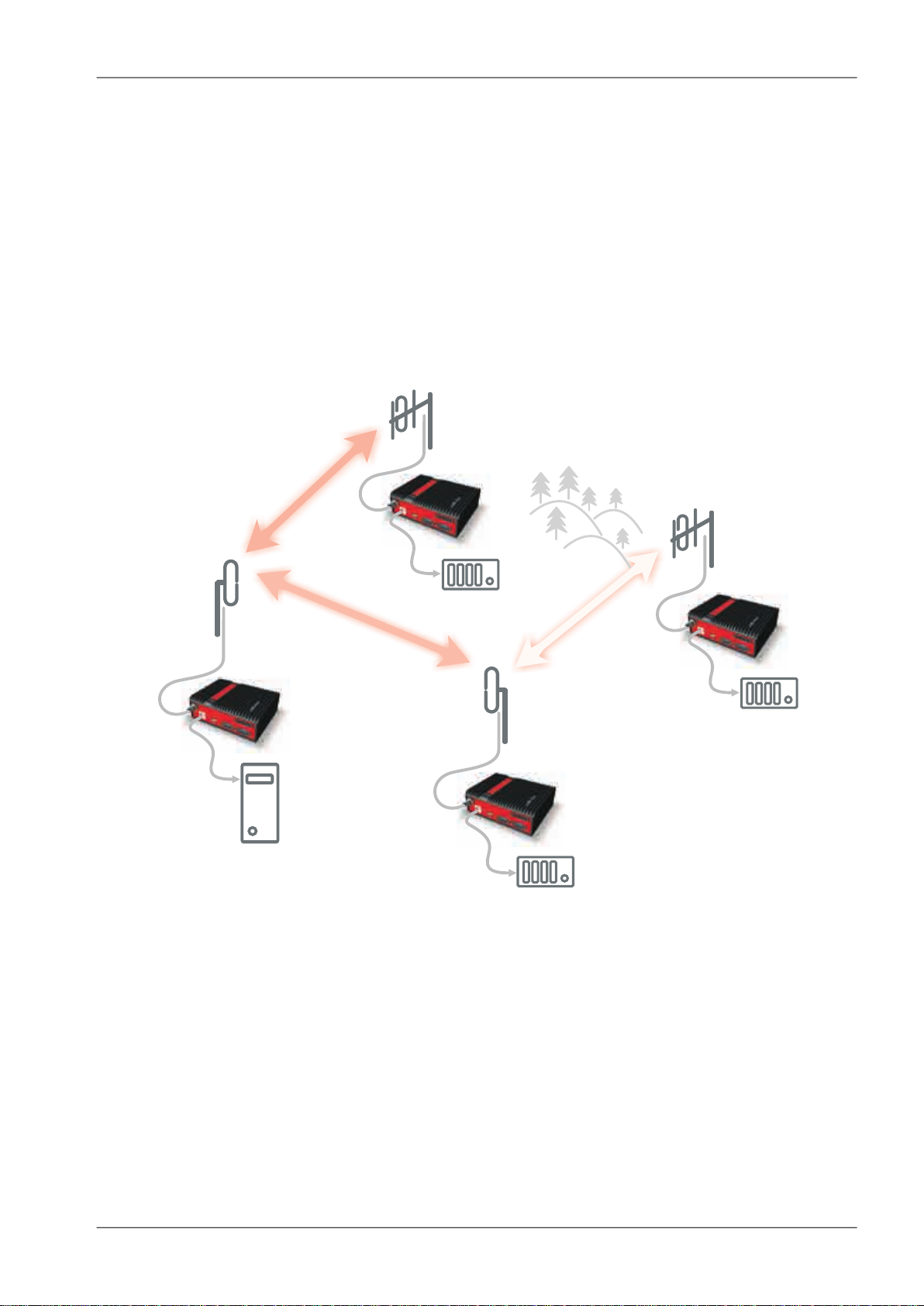
Step 3
RipEX3 and RipEX1 send the received packet to their
COM1 and COM2.
Packet is addressed to RTU3, so only RTU3 responds.
RipEX1 is set as a repeater, so it retransmits the packet
on Radio channel. Packet is received by all RipEXes.
Step 4
RipEX2 sends repeated packet to its COM1 and COM2.
RTU2 doesn’t react, because the packet is addressed to
RTU3.
RipEX3 and FEP’s RipEX do not send the repeated
packet to their COM ports, because it has already been
sent (RipEX3) or received (FEP’s RipEX) on their COM
(anti-duplication mechanism).
RTU3 sends the reply packet.
Step 5
RipEX3 broadcasts the reply packet from RTU3 on Radio
channel.
Packet is received by RipEX1 and FEP’s RipEX.
Step 6
FEP’s RipEX sends the packet (the reply from RTU3) to
FEP through COM1.
RipEX1 sends this packet to RTU1. RTU1 doesn’t react,
because the packet is addressed to FEP.
RipEX1 repeats the packet on Radio channel.
All RipEXes receive the packet.
Step 7
RipEX2 sends repeated packet to its COM1 and COM2.
RTU2 doesn’t react, because the packet is addressed to
FEP.
RipEX3 and FEP’s RipEXes do not send the repeated
packet to their COM ports, because it has been handled
already.
FEP processes the reply from RTU3 and polling cycle
continues…
RipEX Radio modem & Router – © RACOM s.r.o.14
Page 15
192.168.5.51/24
192.168.5.50/24
192.168.5.12/24
192.168.5.2/24
192.168.5.3/24
192.168.5.11/24
192.168.5.1/24
192.168.5.13/24
3
FEP
50
1
2
REPEATER
RipEX in detail
2.2.3. Configuration examples
You can see an example of IP addresses of the SCADA equipment and RipEX's ETH interfaces in the
picture below.
In Bridge mode, the IP address of the ETH interface of RipEX is not relevant for user data communication. However it is strongly recommended to assign a unique IP address to each RipEXs' ETH interface,
since it allows for easy local as well as remote service access. Moreover, leaving all RipEX's with the
same (= default) IP on the ETH interface may cause serious problems, when more RipEX's are connected to the samX5e LAN, even if by accident (e.g. during maintenance).
Fig. 2.1: Bridge mode example
Repeater
Because using the bridge mode makes the network transparent, the use of repeaters has certain limitations. To keep matters simple we recommend using a single repeater. However, if certain rules are
observed, using multiple repeaters in the same network is possible.
The total number of repeaters in the network is configured for every unit individually under Bridge mode
parameters. This information is contained in every packet sent. All units that receive such packet will
resume transmission only after sufficient time has been allowed for the packet to be repeated. The
packets received from user ports remain buffered and are sent after the appropriate time passes. This
prevents collisions between remote radio modems. There can be no repeater collisions if only one repeater is used.
15© RACOM s.r.o. – RipEX Radio modem & Router
Page 16
Centre RPT1 RPT2 Remote
1 2 3
X
COLLISION!
1
1
2
2
WRONG
CEN RPT1 RPT2 REM
GOOD
Coveragearea
1 2 3
CEN RPT1 RPT2 REM
1
2
Good
CEN RPT1 REM
RipEX in detail
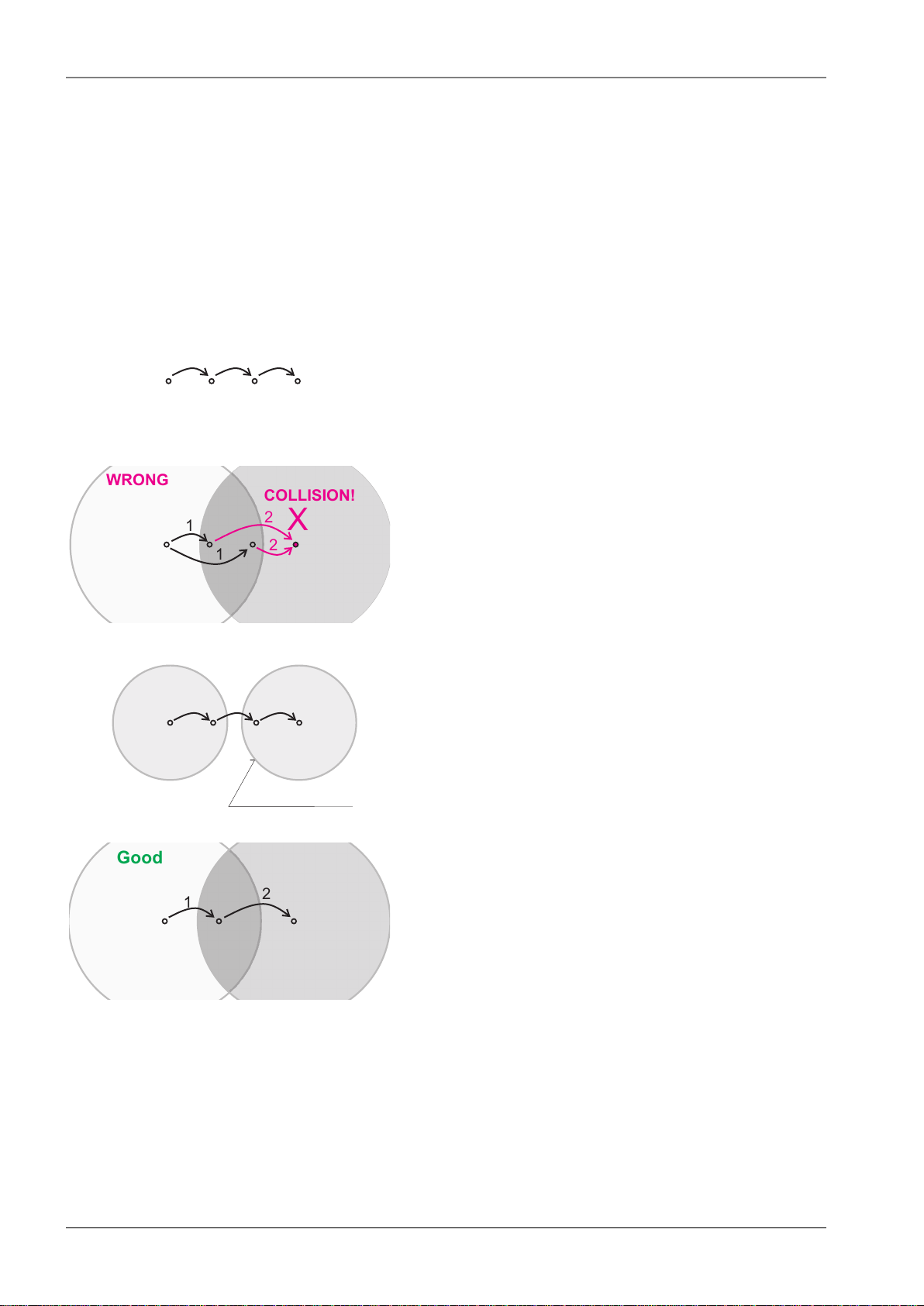
Where two or more repeaters are used, collisions resulting from simultaneous reception of a repeated
packet must be eliminated. Collisions happen because repeaters repeat packets immediately after reception, i.e. if two repeaters receive a packet from the centre, they both relay it at the same time. If
there is a radiomodem which is within the range of both repeaters, it receives both repeated packets
at the same time rendering them unreadable.
Examples:
1. Repeaters connected serially
A packet is transmitted and repeated
in steps 1, 2, 3.
In improperly designed networks collisions happen
if a remote radio modem lies in the range of two
repeaters (see the image): the packet sent from
the centre (1) is received by both repeaters. It is
repeated by them both (2) causing a collision at
the remote. In other words – there should not be
more than one repeater where the centre and remotes' coverage areas overlap.
Solution 1.
Adjust signal coverage so that RPT2 is out of range
of the centre and RPT1 is out of the range of the
remote radio modem. This can be achieved for
example by reducing the output power or using a
unidirectional antenna.
Solution 2.
Use a single repeater. (Whenever network layout
allows that.)
RipEX Radio modem & Router – © RACOM s.r.o.16
Page 17
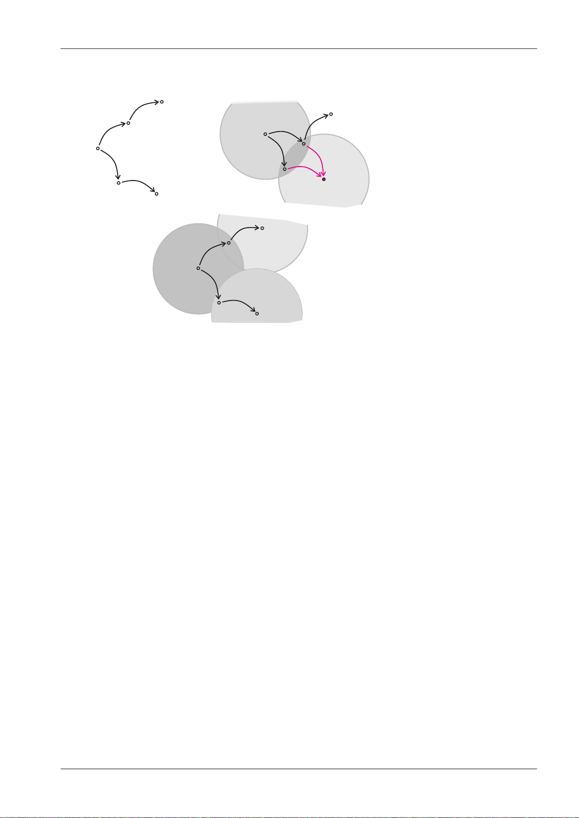
2. Parallel repeaters
Centre
Repeater1
Remote1
1
2
1
2
Remote2
Repeater2
X
COLLISION!
GOOD
WRONG
1
2
1
2
CEN
CEN
RPT1
RPT1
REM1
REM1
1
2
1
2
REM2
REM2
RPT2
RPT2
2
RipEX in detail
Improperly designed network:
- RipEX REM1 is within the range
of two repeaters (RPT1 and RPT2).
The repeaters receive a packet (1)
from the centre (CEN) and repeat
it at the same time (2) causing a
collision at REM1.
Well-designed network:
- A remote is only in the range of a
single repeater (REM1-RPT1,
REM2-RPT2).
There is always only one repeater
where the centre and remote coverage areas overlap.
2.3. Router mode
RipEX works as a standard IP router with two interfaces (radio and ethernet) and two COM port devices.
There is a sophisticated anti-collision protocol on the radio channel, which checks and verifies every
single packet. Being an IP router, each unit can simultaneously work as a store-and-forward repeater
and deliver packets to the connected equipment.
The router mode is suitable for all uses. In contrast to the bridge mode, a packet reception is confirmed
over the radio channel even in very simple polling type applications, and if necessary the packet is retransmitted.
2.3.1. Detailed Description
Router mode is suitable for multipoint networks, where multi-master applications with any combination
of polling and/or spontaneous data protocols can be used. The proprietary link-layer protocol on the
radio channel is very sophisticated, it can transmit both unicast and broadcast frames, it has collision
avoidance capability, it uses frame acknowledgement, retransmissions and CRC checks to guarantee
data delivery and integrity even under harsh interference conditions on the radio channel.
RipEX works as a standard IP router with 2 independent interfaces: radio and ETH. Each interface has
its own MAC address, IP address and mask.
IP packets are processed according the routing table rules. You can also set the router’s default gateway
(applies to both interfaces) in the routing table.
The COM ports are treated as standard host devices, messages can be delivered to them as UDP
datagrams to selected port numbers. The destination IP address of a COM port is either the IP of ETH
or the IP of a radio interface. The source IP address of outgoing packets from COM ports is always the
IP of the ETH interface.
17© RACOM s.r.o. – RipEX Radio modem & Router
Page 18
RipEX in detail
2.3.2. Functionality example
In the following example, there are two independent SCADA devices connected to RipEX's two COM
ports. One is designated RTU (Remote Telemetry Unit) and is assumed to be polled from the centre
by the FEP (Front End Processor). The other is labelled PLC (Programmable Logic Controller) and is
assumed to communicate spontaneously with arbitrary chosen peer PLCs.
Step 1
FEP sends a request packet for RTU1 through COM2 to
its connected RipEX.
Simultaneously PLC2 sends a packet for PLC1 to RipEX2
through COM1.
Step 2
FEP’s RipEX transmits an addressed packet for RTU1 on
Radio channel.
RipEX1 receives this packet, checks data integrity and
transmits the acknowledgement.
At the same time packet is sent to RTU1 through COM2.
RipEX3 receives this packet too. It doesn’t react, because
this packet is directed to RipEX1 only.
Step 3
RipEX2 waits till previous transaction on Radio channel is
finished (anti-collision mechanism).
Then RipEX2 transmits on Radio channel the addressed
packet for PLC1.
RipEX1 receives this packet, checks data integrity and
transmits acknowledgement.
At the same time packet is sent to PLC1 through COM1.
Simultaneously the reply packet from RTU1 for FEP is received on COM2.
Step 4
RipEX1 transmitts the reply packet from RTU1 for FEP on
Radio channel.
All RipEXes receive this packet. This packet is addressed
to FEP’s RipEX, so only FEP’s RipEX reacts. It checks
data integrity and transmits the acknowledgement to
RipEX1.
At the same time the packet is sent to FEP through COM2.
RipEX Radio modem & Router – © RACOM s.r.o.18
Page 19
RipEX in detail
Step 5
FEP receives the response from RTU1 and polling cycle
continues…
However any PLC or RTU can spontaneously send a
packet to any destination anytime.
2.3.3. Configuration examples
As it was mentioned above, RipEX radiomodem works as a standard IP router with two independent
interfaces: radio and ETH. Each interface has got its own MAC address, IP address and mask.
The IP router operating principles stipulate that every unit can serve as a repeater.. Everything what
is needed is the proper configuration of routing tables.
Radio IP addresses of the RipEX’s required to communicate over the radio channel must share the
same IP network. We recommend planning your IP network so that every RipEX is connected to a
separate sub-network over the ethernet port. This helps to keep the routing tables clear and simple.
Note
Even if the IP addresses of all RipEXes in a radio channel share a single IP network, they
may not be communicating directly as in a common IP network. Only the RipEXes that are
within the radio range of each other can communicate directly. When communication with
radio IP addresses is required, routing tables must include even the routes that are within
the same network (over repeaters), which is different from common IP networks. The example
configuration below does not show such routing rules for the sake of simplicity (they are not
needed in most cases).
19© RACOM s.r.o. – RipEX Radio modem & Router
Page 20
10.10.10.50/24
192.168.50.2/24
RoutingtableRipEX50:
192.168.1.0/24 10.10.10.1
192.168.2.0/24 10.10.10.1
192.168.3.0/24 10.10.10.3
DefaultGW192.168.50.2
è
è
è
192.168.2.2/24
Routingtable :
192.168.1.0/24
10.10.10.1
RipEX2
192.168.50.0/24 10.10.10.1
192.168.3.0/24 10.10.10.1
è
è
è
10.10.10.3/24
192.168.3.2/24
RoutingtableRipEX3:
192.168.50.0/24 10.10.10.50
192.168.1.0/24 10.10.10.50
192.168.2.0/24 10.10.10.50
è
è
è
10.10.10.1/24
192.168.1.1/24
192.168.1.2/24
Routingtable :
192.168.2.0/24
10.10.10.2
RipEX1
192.168.50.0/24 10.10.10.50
192.168.3.0/24 10.10.10.50
è
è
è
192.168.3.1/24
3
50
FEP
1
192.168.50.1/24
RadioIP
ETHIP
FEP IP
10.10.10.2/24
2
192.168.2.1/24
RipEX in detail
Fig. 2.2: Addressing
Formal consistency between the last byte of the radio IP address and the penultimate byte of the ethernet address is not necessary but simplifies orientation. The “Addressing” image shows a routing table
next to every RipEX. The routing table defines the next gateway for each IP destination. In radio
transmission, the radio IP of the next radio-connected RipEX serves as the gateway.
Example of a route from FEP (RipEX 50) to RTU 2:
• The destination address is 192.168.2.2
• The routing table of the RipEX 50 contains this record:
• Based on this record, all packets with addresses in the range from 192.168.2.1 to 192.168.2.254
• Because RipEX 50’s radio IP is 10.10.10.50/24, the router can tell that the IP 10.10.10.1 belongs
• The packet is received by RipEX 1 with the address 10.10.10.1 where it enters the router
• The routing table of RipEX 1 contains the record:
• The packet is received by RipEX 2
• The router compares the destination IP 192.168.2.2 with its own ethernet address 192.168.2.1/24
Destination 192.168.2.0/24 Gateway 10.10.10.1
are routed to 10.10.10.1
to the radio channel and sends the packet to that address over the radio channel
Destination 192.168.2.0/24 Gateway 10.10.10.2
based on which the packet is routed to 10.10.10.2 over the radio channel
and determines that the packet’s destination is within its ETH network and sends the packet over
the ethernet interface – eventually, the packet is received by RTU 2.
RipEX Radio modem & Router – © RACOM s.r.o.20
Page 21
10.10.10.50/24
192.168.50.2/24
RoutingtableRipEX50:
192.168.0.0/22 10.10.10.1
192.168.4.0/22 10.10.10.4
DefaultGW192.168.50.2
è
è
10.10.10.2/24
192.168.2.1/24
192.168.2.2/24
Routingtable :
192.168.0.0/16 10.10.10.1
RipEX2
è
10.10.10.4/24
192.168.4.2/24
RoutingtableRipEX4:
192.168.0.0/16 10.10.10.50è
10.10.10.1/24
192.168.1.1/24
192.168.1.2/24
Routingtable :
192.168.2.0/24
10.10.10.2
RipEX1
192.168.0.0/16 10.10.10.50
è
è
192.168.4.1/24
4
50
FEP
1
2
RadioIP
ETHIP
FEP IP
192.168.50.1/24
RipEX in detail
2.3.4. Addressing hints
In large and complex networks with numerous repeaters, individual routing tables may become long
and difficult to comprehend. To keep the routing tables simple, the addressing scheme should follow
the layout of the radio network.
More specifically, every group of IP addresses of devices (both RipEX's and SCADA), which is accessed
via a repeater, should fall in a range which can be defined by a mask and no address defined by that
mask exists in different part of the network.
A typical network consisting of a single centre and number of remotes has got a tree-like layout, which
can be easily followed by the addressing scheme – see the example in the Figure Optimised addressing
below.
Fig. 2.3: Optimised addressing
The default gateway is also a very powerful routing tool, however be very careful whenever the default
route would go to the radio interface, i.e. to the radio channel. If a packet to non-existing IP destination
came to the router, it would be transmitted over the radio channel. Such packets increase the load of
the network at least, cause excessive collisions, may end-up looping etc. Consequently the default
route should always lead to the ETH interface, unless you are perfectly certain that a packet to nonexisting destination IP may never appear (remember you are dealing with complex software written
and configured by humans).
21© RACOM s.r.o. – RipEX Radio modem & Router
Page 22

RipEX in detail
2.4. Serial SCADA protocols
Even when the SCADA devices are connected via serial port, communication remains secured and
address-based in all directions (centre-RTU, RTU-centre, RTU-RTU).
In router mode, RipEX utilises a unique implementation of various SCADA protocols (Modbus, IEC101,
DNP3, Comli, RP570, C24, DF1, Profibus). In this implementation SCADA protocol addresses are
mapped to RipEX addresses and individual packets are transmitted as acknowledged unicasts. Polled
remote units respond to the unit that contacted them (multi master network possible) using secure
packets. When needed, RTU-RTU parallel communication is also possible.
2.4.1. Detailed Description
Each SCADA protocol, such as Modbus, DNP3, IEC101, DF1, etc., has its own unique message format,
and more importantly, its unique way of addressing remote units. The basic task for protocol utility is
to check whether a received frame is in the correct protocol format and uncorrupted. Most of the SCADA
protocols use some type of error detection codes (Checksum, CRC, LRC, BCC, etc.) for data integrity
control, so RipEX calculates this code and check it with the received one.
RipEX radio network works in IP environment, so the basic task for the protocol interface utility is to
convert SCADA serial packets to UDP datagrams. Address translation settings are used to define the
destination IP address and UDP port. Then these UDP datagrams are sent to RipEX router, processed
and typically forwarded as unicasts over the radio channel to their destination. If the gateway defined
in the routing table belongs to the ethernet LAN, UDP datagrams are rather forwarded to the ethernet
interface. After reaching the gateway (typically a RipEX router), the datagram is again forwarded according to the routing table.
Above that, RipEX is can to handle even broadcast packets from serial SCADA protocols. When
broadcasts are enabled in the respective Protocol settings, the defined packets are treated as broadcast
(e.g. they are not acknowledged on Radio channel). On the Repeater station, it is possible to set
whether broadcast packets shall be repeated or not.
Note: UDP datagrams can be acknowledged on the radio channel (ACK parameter of router mode)
but they are not acknowledged on the ethernet channel.
When a UDP datagram reaches its final IP destination, it should be in a RipEX router again (either its
ETH or radio interface). It is processed further according its UDP port. Either it is delivered to COM1(2)
port daemon, where the datagram is decapsulated and the data received on serial interface of the
source unit is forwarded to COM1(2), or the UDP port is that of a Terminal server or any other special
protocol daemon on Ethernet like Modbus TCP etc. Then the datagram is processed by that daemon
accordingly to the respective settings.
RipEX uses a unique, sophisticated protocol on the radio channel. It guaranties data integrity even
under heavy interference or weak signal conditions due to the 32 bit CRC used, minimises the likelihood
of a collision and retransmits frames when collision happens, etc. These features allow for the most
efficient SCADA application arrangements to be used, e.g. multi-master polling and/or spontaneous
communication from remote units and/or parallel communication between remote units, etc.
Note: The anti-collision protocol feature is available only in the router mode. The bridge mode is suitable
for simple Master-Slave arrangements with polling-type application protocol.
RipEX Radio modem & Router – © RACOM s.r.o.22
Page 23

RipEX in detail
2.5. Combination of IP and serial communication
RipEX enables combination of IP and serial protocols within a single application.
Five independent terminal servers are available in RipEX. A terminal server is a virtual substitute for
devices used as serial-to-TCP(UDP) converters. It encapsulates serial protocol to TCP(UDP) and vice
versa eliminating the transfer of TCP overhead over the radio channel.
If the data structure of a packet is identical for IP and serial protocols, the terminal server can serve as
a converter between TCP(UDP)/IP and serial protocols (RS232, RS485).
RipEX also provides a built-in converter Modus RTU – Modus TCP, where data structure is not the
same, so one application may combine both protocols, Modus RTU and Modus TCP.
2.5.1. Detailed Description
Generally, a terminal server (also referred to as serial server) enables connection of devices with a
serial interface to a RipEX over the local area network (LAN). It is a virtual substitute for the devices
used as serial-to-TCP(UDP) converters.
Examples of the use:
A SCADA application in the centre should be connected to the radio network via serial interface, however,
for some reason that serial interface is not used. The operating system (e.g. Windows) can provide a
virtual serial interface to such application and converts the serial data to TCP (UDP) datagrams, which
are then received by the terminal server in RipEX. This type of connection between RipEX and application provides best results when:
• There is no hardware serial interface on the computer
• Serial cable between RipEX and computer would be too long. E.g. the RipEX is installed very close
to the antenna to reduce feed line loss.
• LAN already exists between the computer and the point of installation
Note: The TCP (UDP) session operates only locally between RipEX and the central computer, hence
it does not increase the load on the radio channel.
In special cases, the terminal server can reduce network load from TCP applications . A TCP session
can be terminated locally at the terminal server in RipEX, user data extracted from the TCP messages
and processed as if it came from a COM port. When the data reaches the destination RipEX, it can be
transferred to the RTU either via the serial interface or via TCP (UDP), using the terminal server again.
Please note, that RipEX Terminal server implementation also supports the dynamical IP port change
in every incoming application datagram. In such case the RipEX sends the reply to the port from which
the last response has been received. This feature allows to extend the number of simultaneously
opened TCP connections between the RipEX and the locally connected application up to 10 on each
Terminal server.
2.6. Diagnostics & network management
RipEX radiomodem offers a wide range of built-in diagnostics and network management tools.
23© RACOM s.r.o. – RipEX Radio modem & Router
Page 24

RipEX in detail
2.6.1. Logs
There are ‘Neighbours’ and Statistic logs in RipEX. For both logs there is a history of 20 log files
available, so the total history of saved values is 20 days (assuming the default value of 1440 min. is
used as the Log save period).
Neighbours
The ‘Neighbours’ log provides information about neighbouring units (RipEX’s which can be accessed
directly over the radio channel, i.e. without a repeater). Every RipEX on the network regularly broadcasts
its status, the set of so called “Watched values”: the probability of packet loss when transmitting data
over the radio channel, current supply voltage, internal temperature, measured RF output power, the
Voltage Standing Wave Ratio on the antenna feed line and the total number of packets received from
/ transmitted to ETH, COM1, COM2 interfaces. In addition, the RipEX that records this data in its log
also keeps track of how many times it listened to its neighbouring unit as well as of the RSS and DQ
recorded. See Adv. Conf., Diagnostic for more.
Statistic
The ‘Statistic’ log provides information about the volume of data traffic on all interfaces: radio, ETH,
COM1, COM2. It offers detailed information about the number of transmitted packets, their size and
the throughput per second. Moreover, a detailed division into user and service packets is available for
the radio channel. See chapter Adv. Conf., Diagnostic for more.
2.6.2. Graphs
An independent database periodically stores the Watched values (see 'Neighbours' log above) from
up to five neighbouring RipEX's and from the local one, there including most important values from the
Statistic log. All these values can be displayed as graphs.
The graphs are available in summary and detailed versions. Detailed logging is triggered on when a
threshold value has been reached for the specific item to enable a more detailed investigation into the
units’ operation when an alarm event occurs. Each graph can display two different elements at once,
including their set thresholds. Each of the values may originate from a different RipEX unit.
See chapter Adv. Conf., Graphs for more.
2.6.3. SNMP
RipEX implements an SNMP client ver. 1. The values provided by RipEX are shown in the MIB table.
RipEX also allows generating SNMP traps when thresholds have been reached for the monitored values:
RSScom, DQcom, TXLost[%], Ucc, Temp, PWR, VSWR, ETH[Rx/Tx], COM1[Rx/Tx], COM2[Rx/Tx],
HW Alarm Input.
See chapter RipEX App notes, SNMP for RACOM RipEX1for more.
2.6.4. Ping
To diagnose the individual radio links RipEX is equipped with an enhanced Ping tool. In addition to the
standard info such as the number of sent and received packets or the round trip time, it provides the
1
http://www.racom.eu/eng/products/m/ripex/app/snmp.html
RipEX Radio modem & Router – © RACOM s.r.o.24
Page 25
COMPORTS
MODULE
ROUTER
&
BRIDGE
MODULE
TERMINAL &MODBUSTCP
SERVERS
RADIO
CHANNEL
MODULE
COM1
COM2
ETH
RADIO
virtualcom eth
RipEX
Rx
Tx
Rx
Tx
Rx
Tx
Rx
Tx
Rx
Tx
Rx
Tx
Rx
Tx
RipEX in detail
overall load, the resulting throughput, BER, PER and specific data about the quality of the radio transmission, RSS and DQ for the weakest radio link on the route.
See chapter Adv. Conf., Ping for details.
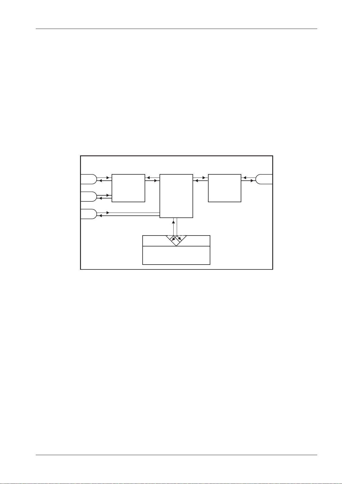
2.6.5. Monitoring
TMonitoring is an advanced on-line diagnostic tool, which enables a detailed analysis of communication
over any of the interfaces of a RipEX router. In addition to all the physical interfaces (RADIO, ETH,
COM1, COM2), some internal interfaces between software modules (e.g. Terminal servers, Modus
TCP server etc.) can be monitored when such advanced diagnostics is needed.
Monitoring output can be viewed on-line or saved to a file in the RipEX (e.g. a remote RipEX) and
downloaded later.
Fig. 2.4: Monitoring
See chapter Adv. Conf., Monitoring for details.
2.7. Firmware update and upgrade
Certain advanced RipEX features are activated with software keys. SW feature keys enable the users
to initially purchase only the functionality they require and buy additional functions as the requirements
and expectations grow. Similarly, when some features (e.g. COM2) are required on certain sites, the
corresponding key can be activated only where needed.
• Keys protect the investment into hardware. Thanks to SDR-based hardware design of RipEX no
physical replacement is necessary – the user simply buys a key and activates the feature.
• For evaluation and testing, Time-limited keys can be supplied. These keys activate the coded feature
for a limited operational (power on) time only. Free Master-key trial for 30 days is in every RipEX.
Software keys are always tied to a specific RipEX production code. A list of possible SW feature keys
and their functionalities is given below:
ROUTER – enables Operating mode Router. If not activated, only Bridge mode is available
25© RACOM s.r.o. – RipEX Radio modem & Router
Page 26

RipEX in detail
83 – enables two highest Data rates
COM2 – enables the second serial interface configurable as RS232 or RS485
10W – enables 10 W RF output power for CPSK modulation
MASTER – enables all functionalities of all possible SW feature keys
See chapter Adv. Conf., Firmware for more.
2.8. Software feature keys
Certain advanced RipEX features are activated with software keys. SW feature keys enable the users
to initially purchase only the functionality they require and buy additional functions as the requirements
and expectations grow. Similarly, when some features (e.g. COM2) are required on certain sites, the
corresponding key can be activated only where needed.
• Keys protect the investment into hardware. Thanks to SDR-based hardware design of RipEX no
physical replacement is necessary – the user simply buys a key and activates the feature.
• For evaluation and testing, Time-limited keys can be supplied. These keys activate the coded feature
for a limited operational (power on) time only. Free Master-key trial for 30 days is in every RipEX.
Software keys are always tied to a specific RipEX production code.
A list of possible SW feature keys and their functionalities is given below:
See chapter Adv. Conf., SW feature keys for more.
RipEX Radio modem & Router – © RACOM s.r.o.26
Page 27

Network planning
3. Network planning
The significance of planning for even a small radio network is often neglected. A typical scenario in
such cases goes as follows – there's not enough time (sometimes money) to do proper planning, so
the network construction is started right away while decisions on antennas etc. are based mainly on
budget restrictions. When the deadline comes, the network is ready but its performance does not meet
the expectations. Finally the (expensive) experts are invited to fix the problem and that fix costs ten
times more than a proper design process done beforehand would have.
The following paragraphs are not a guide to network planning – that is a topic far beyond the scope of
a product manual. What is provided is the essential RipEX data needed plus some comments on
common problems which should be addressed during the planning process.
3.1. Data throughput, response time
A UHF radio network provides very limited bandwidth for principal reasons. Hence the first and very
important step to be taken is estimating/calculating the capacity of the planned network. The goal is to
meet the application bandwidth and time-related requirements. Often this step determines the layout
of the network, for example when high speed is necessary, only near-LOS (Line-of-sight) radio hops
can be used.
RipEX offers an unprecedented range of data rates. The channel width available and signal levels expected/measured on individual hops limit the maximum rate which can be used. The data rate defines
the total capacity of one radio channel in one area of coverage, which is shared by all the radio modems
within the area. Then several overhead factors, which reduce the total capacity to 25-90% of the "raw"
value, have to be considered. They are e.g. RF protocol headers, FEC, channel access procedures
and number of store-and-forward repeaters. There is one positive factor left – an optimum compression
(e.g. IP optimization) can increase the capacity by 20-200%.
All these factors are heavily influenced by the way the application loads the network. For example, a
simple polling-type application results in very long alarm delivery times – an event at a remote is reported
only when the respective unit is polled. However the total channel capacity available can be 60-95%
of the raw value, since there are no collisions. A report-by-exception type of load yields much better
application performance, yet the total channel capacity is reduced to 25-35% because of the protocol
overhead needed to avoid and solve collisions.
The basic calculations of network throughput and response times for different RipEX settings can be
done at www.racom.eu1.
Let us add one comment based on experience. Before committing to the actual network design, it is
very wise to do a thorough bench-test with real application equipment and carefully monitor the load
generated. A difference against the datasheets, which may be negligible in a LAN environment, may
have fundamental consequences for the radio network design. To face that "small" difference when
the network is about to be commissioned may be a very expensive experience. The bench test layout
should include the application centre, two remotes (at least) and the use of a repeater. See the following
picture for an example.
1
http://www.racom.eu/eng/products/radio-modem-ripex.html#calculation
27© RACOM s.r.o. – RipEX Radio modem & Router
Page 28
Centre
RTU
config.PC
RTU
dummy
antenna
Network planning
Fig. 3.1: Application bench test
3.2. Frequency
Often the frequency is simply given. If there is a choice, using the optimum frequency range can make
a significant difference. Let us make a brief comparison of the most used UHF frequency bands.
160 MHz
The best choice when you have to cover a hilly region and repeaters are not an option. The only frequency of the set of options which can possibly make it to a distant valley, 20 km from your nearest
point-of-presence, it can reach a ship 100 km from the shore base. The penalty you pay is tremendous
– high level of noise in urban and industry areas, omnipresent multi-path propagation, vulnerability to
numerous special propagation effects in troposphere etc. Consequently this frequency band is suitable
for low speeds using robust modulation techniques only, and even then a somewhat lower long-term
communication reliability has to be acceptable for the application.
450 MHz
The most popular of UHF frequency bands. It still can get you slightly “beyond the horizon”, while the
signal stability is good enough for 99% (or better) level of reliability. Multi-path propagation can be a
problem, hence high speeds may be limited to near-LOS conditions. Urban and industrial noise does
not pose a serious threat (normally), but rather the interference caused by other transmissions is quite
frequent source of disturbances.
350 MHz
Put simply, character of this band is somewhere between 160 and 450 MHz.
900 MHz
This band requires planning the network in “microwave” style. Hops longer than about 1 km have to
have “almost” clear LOS (Line-of-sight). Of course a 2–5 km link can handle one high building or a
RipEX Radio modem & Router – © RACOM s.r.o.28
Page 29
TX
output
RX
input
feedline
loss
feedline
loss
pathloss
TX
antenna
gain
RX
antenna
gain
+ +
Network planning
bunch of trees in the middle, (which would be a fatal problem for e.g. an 11 GHz microwave). 900 MHz
also penetrates buildings quite well, in an industrial environment full of steel and concrete it may be
the best choice. The signal gets “everywhere” thanks to many reflections, unfortunately there is bad
news attached to this - the reliability of high speed links in such environment is once again limited.
Otherwise, if network capacity is your main problem, then 900 MHz allows you to build the fastest and
most reliable links. The price you pay (compared to lower frequency bands) is really the price – more
repeaters and higher towers increase the initial cost. Long term reliable performance is the reward.
The three frequency bands discussed illustrate the simple basic rules – the higher the frequency, the
closer to LOS the signal has to travel. That limits the distance over the Earth's surface – there is no
other fundamental reason why shorter wavelengths could not be used for long distance communication.
On the other hand, the higher the frequency, the more reliable the radio link is. The conclusion is then
very simple – use the highest frequency band you can.
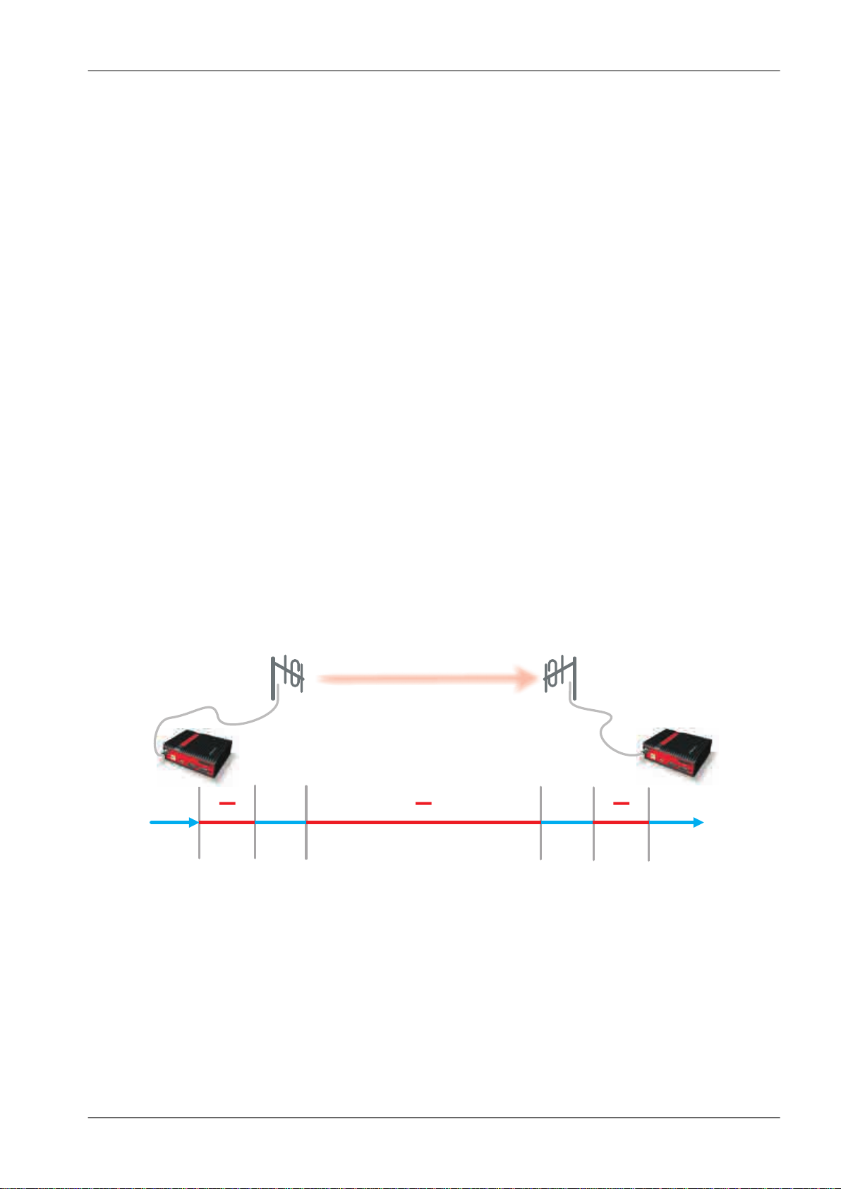
3.3. Signal budget
For every radio hop which may be used in the network, the signal level at the respective receiver input
has to be calculated and assessed against requirements. The fundamental requirements are two – the
data rate, which is dictated by total throughput and response times required by the application, and the
availability, which is again derived from the required reliability of the application. The data rate translates
to receiver sensitivity and the availability (e.g. 99,9 % percent of time) results in size of the fade margin.
The basic rule of signal budget says, that the difference between the signal level at the receiver input
and the guaranteed receiver sensitivity for the given data rate has to be greater than the fade margin
required:
RX signal [dBm] – RX sensitivity [dBm] >= Fade margin [dB]
To calculate the RX signal level, we follow the RF signal path:
Fig. 3.2: Signal path
example:RX signal [dBm] =
dBm (TX output 1 W)+30.0+ TX output [dBm]
dB (20m cable RG-213 U, 400 MHz)-2.5- TX antenna feeder loss [dB]
dBi (half-wave dipole, 0 dBd)+2.1+TX antenna gain [dBi]
dB calculated from field measurement)-125.0- Path loss [dB]
dB (7-al Yagi antenna, 7.6 dBd)+9.7+ RX antenna gain [dBi]
29© RACOM s.r.o. – RipEX Radio modem & Router
Page 30

Network planning
dB (10 m cable RG-58 CU, 400 MHz)-3.1- RX antenna feeder loss [dB]
dBm Received Signal Strength (RSS)= -88.8
The available TX output power and guaranteed RX sensitivity level for the given data rate have to be
declared by the radio manufacturer. RipEX values can be found in Table 4.6, “Technical parameters”
and Chap Section 4.4.1, “Detailed Radio parameters”. Antenna gains and directivity diagrams have to
be supplied by the antenna manufacturer. Note that antenna gains against isotropic radiator (dBi)
are used in the calculation. The figures of feeder cable loss per meter should be also known. Note that
coaxial cable parameters may change considerably with time, especially when exposed to an outdoor
environment. It is recommended to add a 50-100 % margin for ageing to the calculated feeder loss.
3.3.1. Path loss and fade margin
The path loss is the key element in the signal budget. Not only does it form the bulk of the total loss,
the time variations of path loss are the reason why a fade margin has to be added. In reality, very often
the fade margin is the single technical figure which expresses the trade-off between cost and performance of the network. The decision to incorporate a particular long radio hop in a network, despite that
its fade margin indicates 90 % availability at best, is sometimes dictated by the lack of investment in a
higher tower or another repeater. Note that RipEXs Auto-speed feature allows the use of a lower data
rate over specific hops in the network, without the need to reduce the rate and consequently the
throughput in the whole network. Lower data rate means lower (= better) value of receiver sensitivity,
hence the fade margin of the respective hop improves. See the respective Application note to learn
more on the Auto-speed feature.
When the signal path profile allows for LOS between the TX and RX antennas, the standard formula
for free-space signal loss (below) gives reliable results:
Path loss [dB] = 20 * log10 (distance [km]) + 20 * log10 (frequency [MHz]) + 32.5
In the real world the path loss is always greater. UHF radio waves can penetrate obstacles (buildings,
vegetation), can be reflected from flat objects, can bend over round objects, can disperse behind sharp
edges – there are numerous ways how a radio signal can propagate in non-LOS conditions. The additional loss when these propagation modes are involved (mostly combined) is very difficult to calculate.
There are sophisticated methods used in RF design software tools which can calculate the path loss
and its variations (statistical properties) over a computer model of terrain. Their accuracy is unfortunately
very limited. The more obstacles on the path, the less reliable is the result. Such a tool can be very
useful in the initial phase of network planning, e.g. to do the first network layout for the estimate of total
throughput, however field measurements of every non-LOS radio hop should be done before the final
network layout is designed.
Determining the fade margin value is even more difficult. Nevertheless the software tools mentioned
can give some guidance, since they can calculate the statistical properties of the signal. Generally the
fade margin (for given availability) is proportional to the difference between the real path loss and the
LOS path loss over the same distance. Then it is about inversely proportional to frequency (in the UHF
range at least). To give an example for 10 km, non-LOS, hop on 450 MHz, fade margin of 20 dB is a
bare minimum. A field test may help again, provided it is run for longer period of time (hours-days).
RipEX diagnostic tools (ping) report the mean deviation of the RSS, which is a good indication of the
signal stability. A multiple of the mean deviation should be added to the fade margin.
RipEX Radio modem & Router – © RACOM s.r.o.30
Page 31

TXantenna
Network planning
3.4. Multipath propagation, DQ
Multipath propagation is the arch-enemy of UHF data networks. The signal coming out of the receiving
antenna is always a combination of multiple signals. The transmitted signal arrives via different paths,
by the various non-LOS ways of propagation. Different paths have different lengths, hence the waveforms
are in different phases when hitting the receiving antenna. They may add-up, they may cancel each
other out.
Fig. 3.3: Multipath propagation
What makes things worse is that the path length changes over time. Since half the wavelength – e.g.
0.3 m at 450 MHz - makes all the difference between summation and cancellation, a 0.001% change
of a path length (10 cm per 10 km) is often significant. And a small change of air temperature gradient
can do that. Well, that is why we have to have a proper fade margin. Now, what makes things really
bad is that the path length depends also on frequency. Normally this dependency is negligible within
the narrow channel. Unfortunately, because of the phase combinations of multiple waveforms, the
resulting signal may get so distorted, that even the sophisticated demodulating techniques cannot read
the original data. That is the situation known to RF data network engineers – signal is strong enough
and yet “it” does not work.
That is why RipEX reports the, somewhat mystic, figure of DQ (Data Quality) alongside the RSS. The
software demodulator uses its own metrics to assess the level of distortion of the incoming signal and
produces a single number in one-byte range (0–255), which is proportionate to the “quality” of the signal.
Though it is very useful information, it has some limitations. First, it is almost impossible to determine
signal quality from a single packet, especially a very short one. That results in quite a jitter of DQ values
when watching individual packets. However when DQ keeps jumping up and down it indicates a serious
multipath problem. In fact, when DQ stays low all the time, it must be noise or permanent interference
behind the problem. The second issue arises from the wide variety of modulation and data rates RipEX
supports. Though every attempt has been made to keep the DQ values modulation independent, the
differences are inevitable. In other words, experience is necessary to make any conclusions from DQ
reading. The less experience you have, the more data you have to collect on the examined link and
use other links for comparison.
The DQ value is about proportional to BER (bit error ratio) and about independent of the data rate and
modulation used. Hence some rule-of-thumb values can be given. Values below 100 mean the link is
unusable. For a value of 125, short packets should get through with some retransmissions, 150–200
means occasional problems will exist (long term testing/evaluation of such link is recommended) and
values above 200 should ensure reliable communication.
31© RACOM s.r.o. – RipEX Radio modem & Router
Page 32

TXantenna
better
multipath
Network planning
3.4.1. How to battle with multipath propagation?
The first step is the diagnosis. We have to realize we are in trouble and only a field measurement can
tell us that. We should forget about software tools and simply assume that a multipath problem may
appear on every non-LOS hop in the network.
These are clear indicators of a serious multipath propagation problem:
• directional antennas "do not work", e.g. a dipole placed at the right spot yields a better RSS than
a long Yagi, or rotating the directional antenna shows several peaks and troughs of the signal and
no clear maximum
• RSS changes rapidly (say 10 dB) when antenna is moved by less than a meter in any direction
• ping test displays the mean deviation of RSS greater than 6 dB
• DQ value keeps "jumping" abnormally from frame to frame
Quite often all the symptoms mentioned can be observed at a site simultaneously. The typical "beginner"
mistake would be to chase the spot with the best RSS with an omnidirectional antenna and installing
it there. Such a spot may work for several minutes (good luck), sometimes for several weeks (bad luck,
since the network may be in full use by then). In fact, installing in such a spot guaranties that trouble
will come - the peak is created by two or more signals added up, which means they will cancel out
sooner or later.
The right strategy is to find an arrangement where a single signal becomes dominant, possibly the
most stable one. "Sweeping" a directional antenna around the place (in different heights and with different polarization) can tell us where the signals come from. If individual signals come from different
directions, there is a good chance a long yagi can solve the problem by selecting just one of the bunch.
Finding a spot where the unwanted signal is blocked by a local obstacle may help as well (e.g. installing
at a side of the building instead of at the roof).
Fig. 3.4: Antenna location
When the multiple signals come from about the same direction, a long yagi alone would not help much.
We have to move away from the location, again looking for a place where just one of the signals becomes
dominant. 20–50 metres may save the situation, changing the height (if possible) is often the right
solution. Sometimes changing the height means going down, not up, e.g. to the base of the building
or tower.
We have to remember our hop has two ends, i.e. the solution may be to change antenna or its placement
at the opposite end. If everything fails, it is better to use another site as a repeater. Even if such prob-
RipEX Radio modem & Router – © RACOM s.r.o.32
Page 33

combiner
correctly
incorrectly
Network planning
lematic site seems to be usable after all (e.g. it can pass commissioning tests), it will keep generating
problems for ever, hence it is very prudent to do something about it as early as possible.
Note: Never design hops where a directional antenna is used for a direction outside its main lobe.
However economical and straightforward it may seem, it is a dangerous trap. Enigmatic cases of dropouts lasting couple of minutes every other day, over a clear LOS hops were created exactly like that.
They look like interference which is very difficult to identify and , alas, they are caused by pure multipath
propagation, a self-made one. So always use a combiner and another directional antenna if such arrangement is needed. Always.
Fig. 3.5: Main lobe
3.5. Network layout
Certainly the network layout is mostly (sometimes completely) defined by the application. When the
terrain allows for direct radio communication among all sites in the network, the designer can do neither
too good nor too bad a job. Fortunately for RF network designers, the real world is seldom that simple.
The conditions every single radio hop has to meet were discussed in previous paragraphs. If we are
so lucky, that different layouts meeting that conditions are possible, we should exploit that for the benefit of the network. The following rules should be followed when defining the layout of radio hops:
33© RACOM s.r.o. – RipEX Radio modem & Router
Page 34

M
Repeater
Centre
incorrectly
M
Centre
Network planning
• dominant radio sites (e.g. telco towers on hill tops) should be avoided whenever possible. Placing
a single repeater which serves most part of the network from the top of a hill is a straightforward
but worst alternative, which makes the whole network very vulnerable. First, a dominant site is exposed to interference from a large area; second, such site is typically crowded with radio equipment
of all kinds, which keeps being added, moved (also failing to work properly), so local interference
may appear anytime; third, it makes the majority of communication paths dependent on a single
site, so one isolated failure may stop almost the entire network.
• when total throughput is important, typically in report-by-exception networks, splitting the network
into several independent or only slightly overlapping areas of coverage can help. The placement
of repeaters which serve the respective areas is crucial. They should be isolated from each other
whenever possible.
Fig. 3.6: Dominant repeater
Fig. 3.7: Isolated branches
RipEX Radio modem & Router – © RACOM s.r.o.34
Page 35

Network planning
• in report-by-exception networks the load of hops connecting the centre to major repeaters forms
the bottle-neck of total network capacity. Moving these hops to another channel, or, even better, to
a wire (fibre, microwave) links can multiply the throughput of the network. It saves not only the load
itself, it also significantly reduces the probability of collision. More on that in the following chapter
3.6..
3.6. Hybrid networks
If an extensive area needs to be covered and multiple retranslation would be uneconomical or unsuitable,
RipEX’s can be interconnected via any IP network (WLAN, Internet, 3G, etc.). This is quite simple because RipEX is a standard IP router with an ethernet interface. Consequently interconnecting two or
more RipEX's over a nested IP network is a standard routing issue and the concrete solution depends
on that network.
3.7. Assorted practical comments
Let us mention few issues, whose influence on network reliability or performance is sometimes neglected
by less experienced planners:
• Both vegetation and construction can grow. Especially when planning a high data rate hop which
requires a near-LOS terrain profile, take into consideration the possible future growth of obstacles.
• When the signal passes a considerable amount of vegetation (e.g. a 100m strip of forest), think of
the season. Typically the path loss imposed by vegetation increases when the foliage gets dense
or wet (late spring, rainy season). Hence the fade margin should be increased if your field measurements are done in a dry autumn month. The attenuation depends on the distance the signal must
penetrate through the forest, and it increases with frequency. According to a CCIR, the attenuation
is of the order of 0.05 dB/m at 200 MHz, 0.1 dB/m at 500 MHz, 0.2 dB/m at 1 GHz. At lower frequencies, the attenuation is somewhat lower for horizontal polarization than for vertical, but the difference
disappears above about 1 GHz.
• Though being a rare problem, moving metallic objects may cause serious disruptions, especially
when they are close to one end of the radio hop. They may be cars on a highway, blades of a wind
turbine, planes taking off from a nearby airport runway etc.
• Even when the signal is very strong, be careful when considering various cheap whips or more
generally any antennas requiring a ground plane to function properly. A tempting scenario is to use
the body of the metallic box, where the radio modem and connected application equipment (often
a computer) is installed, as the ground plane, which leads to never-ending problems with locally
35© RACOM s.r.o. – RipEX Radio modem & Router
Page 36

incorectly
correctly
Powersupply
RTU
Network planning
generated noise. The ground plane forms an integral part of such an antenna, hence it has to be
in a safe distance (several metres) from any electronic equipment as well as the antenna itself. A
metallic plate used as shielding against interference must not form a part of the antenna.
Fig. 3.8: Antenna mounting
• Do not underestimate ageing of coaxial cables, especially at higher frequencies. Designing a 900
MHz site with 30 m long antenna cable run outdoors would certainly result in trouble two years later.
• We recommend to use vertical polarization for all radio modem networks.
3.8. Recommended values
To check individual radio link quality run Ping test with these settings: Ping type - RSS, Length [bytes]
equal to the longest packets in the networks. Use Operating mode Bridge, when Router, ACK set to
Off. Switch off all other traffic on the Radio channel used for testing. The test should run at least hours,
preferrably day(s). The values below should guarantee a reliable radio link:
• Fade margin
Min. 20 dB
Fade margin [dB] = RSS (Received Signal Strenght) [dBm] – RX sensitivity [dBm].
Respective RX sensitivity for different data rates can be found in Section 4.4.1, “Detailed Radio
parameters”.
RipEX Radio modem & Router – © RACOM s.r.o.36
Page 37

• DQ (Data Quality)
Min. 180
• PER (Packet Error Rate)
Max. 5 %
Network planning
37© RACOM s.r.o. – RipEX Radio modem & Router
Page 38

DIN35Rail
DINRailClip
134
150
118
58
50
133
95
124
60
122
122
175
L -bracket
Flat-bracket
8
70
2×o4,5 4×M3
/
Product
4. Product
RipEX is built into a rugged die-cast aluminium casing that allows for multiple installation possibilities,
see Section 6.1, “Mounting”.
4.1. Dimensions
Fig. 4.1: RipEX dimensions, see more
Fig. 4.2: L-bracket and Flat-bracket, see more
RipEX Radio modem & Router – © RACOM s.r.o.38
Page 39

ALARMOUT.
ALARMINPUT
+ –
SLEEP -WAKEUP
COM1
COM2dataequipment,RTU
ETHdataequipment,RTU
LAN,controlPC
ETH/USB ADAPTER
ANTENNA
10–30VDC
+
+
ETH
Product
4.2. Connectors
All connectors are located on the front panel. The upper side features an LED panel. The RESET button
is located in an opening in the bottom side.
Fig. 4.3: Connectors
4.2.1. Antenna
An antenna can connect to RipEX via TNC female 50Ω connector.
A model with two antenna connectors can be supplied to order,
in which the Rx and Tx antennas are separate. See chapter
Section 4.5, “Model offerings”.
Fig. 4.4: Antenna connector TNC
39© RACOM s.r.o. – RipEX Radio modem & Router
Page 40

Product
Fig. 4.5: Separated Rx and TX antennas
Warning: RipEX radio modem may be damaged when operated without an antenna or a dummy load.
4.2.2. Power and Control
This rugged connector connects to a power supply and it contains control signals. A Plug with screwterminals and retaining screws for power and control connector is supplied with each RipEX. It is Tyco
7 pin terminal block plug, part No. 1776192-7, contact pitch 3.81 mm. The connector is designed for
electric wires with a cross section of 0.5 to 1.5 mm2. Strip the wire leads to 6 mm (1/4 inch). Isolated
cables should receive PKC 108 or less end sleeves before they are inserted in the clip. Insert the cables
in the wire ports, tightening securely.
Tab. 4.1: Pin assignement
signallabeledpin
SLEEP INPUTSI1
HW ALARM INPUTAI2
−3
−(GND) – for SLEEP IN, HW ALARM
INPUT
+(POWER) – for HW ALARM OUTPUT+4
HW ALARM OUTPUTAO5
+POWER (10 to 30 V)+ 10–30VDC6
−POWER (GND)− 10–30VDC7
Pins 3 and 7, 4 and 6 are connected internally.
RipEX Radio modem & Router – © RACOM s.r.o.40
Page 41

1 2 3 4 5 6PinNo.: 7
SI AI - + A 0
+
-
10–30 VDC
Wire
Ports(7)
Retaining
Screws(2)
Lead
Binding
Screws(7)
1 2 3 4 5 6PinNo.: 7
SI AI - + A0
+
-
10– 30VD C
SleepInput
1 2 3 4 5 6PinNo.: 7
SI AI - + A0
+
-
10– 30VD C
AlarmInput
1 2 3 4 5 6PinNo.: 7
SI AI - + A0
+
-
10– 30VD C
AlarmOutput
max.30VDC,1 A
Product
Fig. 4.6: Supply connector
Fig. 4.7: Power and Control - cable plug
SLEEP INPUT
SLEEP INPUT is the digital input for activating the Sleep mode.
When this pin is grounded (for example when connected to pin
3), the RipEX switches into the Sleep mode. Using Power management (Advanced Config.), the Entering the Sleep mode can
be delayed by a set time. Disconnecting SLEEP INPUT from
GND (-) ends the Sleep mode. Note that RipEX takes 25 seconds
to wake up from the Sleep mode.
HW ALARM INPUT
HWALARM INPUT is a digital input. If grounded (e.g. by connecting to PIN 3), an external alarm is triggered. This alarm can be
used for example to transmit information using SNMP trap, informing for instance about a power outage or RTU problem. For
details about Alarm management see chapter Advanced Config-
uration.
HW ALARM OUTPUT
HW ALARM OUTPUT is a digital output. It can be activated
in Alarm management settings, chapter Advanced Configuration.
It may be used for instance to switch on the Fan kit if the preset
maximum internal temperature is exceeded or to inform the
connected RTU about a RipEX alarm. If an alarm is triggered,
HW ALARM OUTPUT is internally connected to GND. If the external device requires connection to positive terminal of the power
supply, PIN 4 should be used.
POWER
The POWER pins labelled + and - serve to connect a power supply 10–30 VDC. The requirements for
a power supply are defined in Section 6.6, “Power supply” and Section 4.4, “Technical specification”.
41© RACOM s.r.o. – RipEX Radio modem & Router
Page 42

Product
4.2.3. ETH
Standard RJ45 connector for ethernet connection. RipEX has 10/100 BaseT Auto MDI/MDIX interface
so it can connect to 10 Mbps or 100 Mbps ethernet network. The speed can be selected manually or
recognised automatically by RipEX. RipEX is provided with Auto MDI/MDIX function which allows it to
connect over both standard and cross cables, adapting itself automatically.
Pin assignement
Tab. 4.2: Ethernet to cable connector connections
Crossed cableDirect cableSignalPIN
green – whiteorange – whiteTX+1
greenorangeTX−2
orange – whitegreen – whiteRX+3
blueblue—4
blue – whiteblue – white—5
orangegreenRx−6
brown – whitebrown – white—7
brownbrown—8
Fig. 4.8: RJ-45F
4.2.4. COM1 and COM2
RipEX provides two serial interfaces COM1 and COM2 terminated by DSUB9F connectors. COM1 is
always RS232, COM2 can be configured as RS232 or RS485 (more in Adv. Conf., COM's).
RipEX‘s RS232 is a hard-wired DCE (Data Communication Equipment) device. Equipment connected
to the RipEX’s serial ports should be DTE (Data Terminal Equipment) and a straight-through cable
should be used. If a DCE device is connected to the RipEX‘s serial ports, a null modem adapter or
cross cable has to be used.
Tab. 4.3: COM1,2 pin description
COM2 – RS485COM1, 2 – RS232DSUB9F
In/ OutsignalIn/ Outsignalpin
—OCD1
I/Oline BORxD2
I/Oline AITxD3
—IDTR4
GNDGND5
—ODSR6
—IRTS7
—OCTS8
———9
RipEX keeps pin 6 DSR at the level of 1 by RS232 standard permanently.
RipEX Radio modem & Router – © RACOM s.r.o.42
Fig. 4.9: Serial connector
Page 43

1 2 3 4
Product
4.2.5. USB
RipEX uses USB 1.1, Host A interface. USB interface is wired as standard:
Tab. 4.4: USB pin description
wiresignalUSB pin
red+5 V1
whiteData(−)2
greenData (+)3
blackGND4
The USB interface is designed for the connection to the "X5" – external ETH/USB adapter. The "X5"
is an optional accessory to RipEX, for more see Section 5.3, “Connecting RipEX to a programming
PC”. The adapter is used for service access to RipEX’s web configuration interface.
The USB connector also provides power supply (5 V/ 0.5 A). It can be used to temporarily power a
connected device, for instance a telephone. The USB connector should not be used as permanent
source of power supply.
Fig. 4.10: Serial connector
4.2.6. Reset button
RipEX’s bottom-side enclosure includes a reset button accessible through
an opening. When this button is pressed, the STATUS diode on the LED
panel goes dark (indicating that the button has been pressed). If you hold
the button for 5 seconds, the STATUS diode starts flashing slowly indicating that the reset is complete. If you continue to hold the button for 15 or
more seconds (the STATUS diode starts flashing quickly) and then release
it, you will reset the device’s access information to default: parameters
such as the login, password and ethernet IP will be reset to their defaults.
Resetting access parameters to defaults also sets the Ethernet speed to
„Auto“ and results in clearing all firewall rules (which may have been
blocking the access by accident). Remember to re-install your firewall if you are using one.
Note
To reset the RipEX only use the RESET button as described above or use the button in RipEX’s web
configuration, see Adv. Conf., Maintenance. Never use a power cycling (disconnecting and reconnecting
power supply) to reset it. While power cycle resets, or rather reboots the RipEX, its software will not
terminate correctly resulting in logs, statistics and graphs not being saved properly.
Fig. 4.11: Reset
4.2.7. GPS
RipEX can be equipped with an internal GPS, see Section 4.5,
“Model offerings”. The GPS module is used for time synchronisation
of the NTP server inside RipEX. See Adv. Conf., Time for more. In
this case the front panel contains a SMA female 50 ohm connector
for connecting the GPS antenna.
Fig. 4.12: GPS Connector SMA
43© RACOM s.r.o. – RipEX Radio modem & Router
Page 44

Product
4.3. Indication LEDs
Tab. 4.5: Key to LEDs
DescriptionColor
STATUS
RX
COM2
COM1
Green
Green flashes slowly
Green flashes quickly
Green
Yellow
The RipEX OS (Linux) is running
succesfuly
Reset button has been pressedDark
reset after five-seconds pressing
the Reset button
default access after 15-seconds
pressing the Reset button
Status alarmRed
transmitting to radio channelRedTX
receiver is synchronised to a
packet
there is a signal stronger than
−80 dBm on Radio channel
data receivingGreen
data transmittingYellow
data receivingGreen
data transmittingYellow
100 Mb/s speedYellow ON
Fig. 4.13: Indication LEDs
ETH
PWR
10 Mb/s speedYellow OFF
connectedGreen ON
ethernet dataGreen flashes
powered succesfulyGreen
Save modeBlinks with a period of 1 sec
Sleep modeFlashes once per 3 sec
RipEX Radio modem & Router – © RACOM s.r.o.44
Page 45

4.4. Technical specification
Tab. 4.6: Technical parameters
Radio parameters
Product
Frequency bands
Modulation
RF Data rate – CE
Detail
RF Data rate – FCC
Detail
25 kHz
12.5 kHz
6.25 kHz
25 kHz
12.5 kHz
6.25 kHz
135–154; 154–174; 300–320; 320–340; 340–360; 368–400;
400–432; 432–470; 928–960* MHz
6.25/12.5/25 kHzChannel spacing
±1.0 ppmFrequency stability
Linear: 16DEQAM, D8PSK, π/4DQPSK, DPSK
Exponencial (FM): 4CPFSK, 2CPFSK
Lin.: 83.33 – 62.50 – 41.67 kbps
Exp.: 20.83 – 10.42 kbps
41.67 – 31.25 – 20.83 kbps
10.42 – 5.21 kbps
20.83 – 15.63 – 10.42 kbps
5.21 – 2.60 kbps
69.44 – 52.08 – 34.72 kbps
20.83 kbps
34.72 – 26.04 – 17.36 kbps
10.42 kbps
17.36 – 13.02 – 8.68 kbps
5.21 kbps
On/Off, ¾ Trellis code with Viterbi soft-decoderFEC (Forward Error Correction)
Detail
max. 2 W
max. 10 W
max. 2 W
max. 10 W
max. 2 W
max. 10 W
max. 2 W
max. 10 W
max. 2 W
max. 10 W
max. 2 W
max. 10 W
Transmitter
RF Output power
(Both Carrier and Modulated)
Receiver
Linear: 0.5 - 1.0 - 2.0 W
Exponencial(FM): 0.1 - 0.2 - 0.5 - 1.0 - 2.0 - 3.0 - 4.0 - 5.0 - 10**W
ContinuousDuty cycle
< 1.5 msRx to Tx Time
> 40 dBIntermodulation Attenuation
< −36 dBmSpurious Emissions (Conducted)
< −36 dBmRadiated Spurious Emissions
< −60 dBcAdjacent channel power
< −60 dBcTransient adjacent channel power
DetailSensitivity
50 kHz @ −3 dB BWAnti-aliasing Selectivity
< 1.5 msTx to Rx Time
20 dBm (100 mW)Maximum Receiver Input Power
< −57 dBmRx Spurious Emissions (Conducted)
< −57 dBmRadiated Spurious Emissions
DetailBlocking or desensitization
45© RACOM s.r.o. – RipEX Radio modem & Router
Page 46

Product
> 70 dBSpurious response rejection
* not available yet,
** For output power 10 W it is recommended to use input power above 11 VDC
Electrical
10 to 30 VDC, negative GNDPrimary power
5 W/13.8 V; 4.8 W/24 V; (Radio part < 2 W)Rx
Power consumtionRF power
13.8 V 24V
Tx
4CPFSK, 2CPFSK
Tx
16DEQAM, D8PSK,
π/4DQPSK
Interfaces
COM 1
COM 2
13.8 W 13.2 W0.1 W
15.2 W 14.4 W1 W
33.1 W 31.2 W5 W
41.4 W 38.4 W10 W
30.4 W 30 W0.5 W
30.4 W 30 W1 W
30.4 W 30 W2 W
0.1 WSleep mode
2 WSave mode
RJ4510/100 Base-T Auto MDI/MDIXEthernet
DB9FRS232
300–115 200 bps
DB9FRS232/RS485 SW configurable
300–115 200 bps
Host AUSB 1.1USB
TNC female50 ΩAntenna
LED panel
Enviromental
Mechanical
SW
Power, ETH, COM1, COM2, Rx, Tx, Status7× tri-color status LEDs
IP40IP Code (Ingress Protection)
> 100 000 hoursMTBF (Mean Time Between Failure)
−40 to +70 °C (−40 to +158 °F)Operating temperature
5 to 95 % non-condensingOperating humidity
−40 to +85 °C (−40 to +185 °F) / 5 to 95 % non-condensingStorage
Rugged die-cast aluminiumCasing
50 H × 150 W × 118 mm D (1.97× 5.9 × 4.65 in)Dimensions
1.1 kg (2.4 lbs)Weight
DIN rail, L-bracket, Flat-bracket, 19" Rack shelfMounting
RipEX Radio modem & Router – © RACOM s.r.o.46
Page 47

Protocol on Radio channel
Product
Bridge / RouterOperating modes
Modbus, IEC101, DNP3, UNI, Comli, DF1, RP570, Profibus…User protocols on COM
Modbus TCP, IEC104, DNP3 TCP, Comli TCP Terminal server…User protocols on Ethernet
Modbus RTU / Modbus TCP, DNP3 / DNP3 TCPSerial to IP convertors
YesMulti master applications
YesReport by exception
YesCollision Avoidance Capability
YesRemote to Remote communication
Addressed & acknowledged serial
SCADA protocols
Diagnostic and Management
Watched values (Can be broadcast
to neighbouring units. Received info
displayed in Neighbours table)
Statistics
Graphs)
SNMP
Yes
CRC 32Data integrity control
AES256Encryption
up to 3× higher throughputOptimization
Yes (ping with RSS, Data Quality, Homogenity)Radio link testing
Device – Ucc, Temp, PWR, VSWR, *HW Alarm Input.
Radio channel – *RSScom, *DQcom, TXLost[%]
User interfaces – ETH[Rx/Tx], COM1[Rx/Tx], COM2[Rx/Tx]
* not broadcast
For Rx/Tx Packets on User interfaces (ETH, COM1, COM2) and
for User data and Radio protocol (Repeates, Lost, ACK etc.) on
Radio channel
For Watched values and StatisticsGraphs
20 periods (configurable, e.g. days)History (Statistics, Neighbours,
SNMPv1, SNMPv2
Trap alarms generation for Watched values
Monitoring
Standards
CE, FCC, RoHS
EMC (electromagnetic compatibility)
(art 3.1.b)
Real time/Save to file analysis of all physical interfaces (RADIO,
ETH, COM1, COM2) and some internal interfaces between
software modules (e.g. Terminal servers, Modus TCP server
etc.)
ETSI EN 300 113-2 V1.5.1Spectrum (art 3.2)
FCC Part 90
ETSI EN 301 489-1 V1.9.2
ETSI EN 301 489-5 V1.3.1
EN 60950-1:2006Safety (art 3.1.a)
EN 60950–1:2006/A11:2009,
EN 60950–1:2006/A12:2011,
EN 60950–1:2006/A1:2010
47© RACOM s.r.o. – RipEX Radio modem & Router
Page 48

Product
Tab. 4.7: Recommended Cables
LenghtRecommended cables and accessoriesPort
Max. 3 mV03VH-H 2×0,5DC terminals – Power
Max. 3 mV03VH-H 1×0,5SI (Sleep Input)
Max. 3 mV03VH-H 1×0,5AI (Alarm Input)
Max. 3 mV03VH-H 1×0,5AO (Alarm Outout)
Max. 3 mLiYCY 4×0,14COM1
Max. 3 mLiYCY 4×0,14COM2
Max. 3 mUSB to 10/100 Ethernet Adapter ADE-X5USB
As neededSTP CAT 5eETH
RipEX Radio modem & Router – © RACOM s.r.o.48
Page 49

Product
4.4.1. Detailed Radio parameters
The very first parameter which is often required for consideration is the receiver sensitivity. Anyone
interested in the wireless data transmission probably aware what this parameter means, but we should
regard it simultaneously in its relation to other receiver parameters, especially blocking and desensitization. Today’s wireless communication arena tends to be overcrowded and a modern radio modem,
which is demanded to compete with others in that environment, should have good dynamic range that
is defined by the parameters listed above. Receiver of a radio modem, which is designed purely for
optimum sensitivity, will not be able to give proper performance. However, the main receiver parameters
determining its dynamic range go against each other and a clear trade-off between the sensitivity and
the blocking is therefore an essential assumption. Then, from the viewpoint of a logical comparison,
the consequence of better receiver sensitivity can be easily seen – a lower power level of the blocking
and degradation parameters generally.
Blocking or desensitization values were determined according to the standards EN 300 113-2 V1.5.1,
resp. EN 300 113-1 V1.7.1 (channels 25 and 12.5 kHz) and ETSI 301 166-1 V1.3.2 (channel 6.25 kHz)
respectively.
Tab. 4.8: CE 25 kHz
CE 25 kHz
Blocking or
desensitization [dBm]Sensitivity [dBm]Classification
-2
EmissionModulationFECkbps
BER 10
BER 10
-3
-6
±10 MHz±5 MHz±1 MHzBER 10
-5-6-8-111-115-11813K8F1DCN2CPFSK0.757.81
-7-8-10-110-114-11713K8F1DBN2CPFSK1.0010.42
-7-9-9-107-112-11514K2F1DDN4CPFSK0.7515.63
-9-11-11-104-110-11314K2F1DDN4CPFSK1.0020.83
-5-6-6-107-112-11424K0G1DCNDPSK0.7515.62
-7-8-8-106-111-11324K0G1DBNDPSK1.0020.83
-3-4-4-106-110-11324K0G1DDNπ/4-DQPSK0.7531.25
-5-6-6-104-108-11124K0G1DDNπ/4-DQPSK1.0041.66
-8-8-8-98-103-10624K0G1DEND8PSK0.7546.87
-9.5-10-10-95-101-10424K0G1DEND8PSK1.0062.49
-5-6-6-95-101-10424K0D1DEN16DEQAM0.7562.49
-7-8-8-93-99-10224K0D1DEN16DEQAM1.0083.32
49© RACOM s.r.o. – RipEX Radio modem & Router
Page 50

Product
Tab. 4.9: CE 12.5 kHz
CE 12.5 kHz
Blocking or
desensitization [dBm]Sensitivity [dBm]Classification
-2
EmissionModulationFECkbps
BER 10
BER 10
-3
-6
±10 MHz±5 MHz±1 MHzBER 10
-3-4-6-113-117-1207K00F1DCN2CPFSK0.753.91
-5-6-8-112-116-1197K00F1DBN2CPFSK1.005.21
-5-6-6-108-114-1177K00F1DDN4CPFSK0.757.81
-7-8-8-105-112-1157K00F1DDN4CPFSK1.0010.42
-3-4-4-110-114-11611K9G1DCNDPSK0.757.81
-5-6-6-109-113-11511K9G1DBNDPSK1.0010.42
-2-3-3.5-109-113-11511K9G1DDNπ/4-DQPSK0.7515.62
-3-4-4-106-111-11411K9G1DDNπ/4-DQPSK1.0020.83
-5-6-6-101-106-10911K9G1DEND8PSK0.7523.44
-7-8-8-98-104-10711K9G1DEND8PSK1.0031.25
Tab. 4.10: CE 6.25 kHz
-2-3-3-99-104-10711K9D1DEN16DEQAM0.7531.25
-4-5-5-96-102-10511K9D1DEN16DEQAM1.0041.67
CE 6.25 kHz
Blocking or
desensitization [dBm]Sensitivity [dBm]Classification
-2
EmissionModulationFECkbps
BER 10
BER 10
-3
-6
±10 MHz±5 MHz±1 MHzBER 10
+5.5+1.0-0.5-114-120-1223K00F1DCN2CPFSK0.751.96
+4.0-1.0-2.5-113-119-1213K00F1DBN2CPFSK1.002.61
+5.0-0.0-1.5-111-116-1193K00F1DDN4CPFSK0.753.91
+3.0-1.5-3.5-108-114-1173K00F1DDN4CPFSK1.005.21
7.01.50.0-113-118-1216K0G1DDPSK0.753.91
5.0-0.5-2.0-112-117-1196K0G1DDPSK1.005.21
6.03.0+1.0-112-115-1176K0G1Dπ/4-DQPSK0.757.82
4.01.0-0.5-110-113-1166K0G1Dπ/4-DQPSK1.0010.42
4.01.0-1.0-104-109-1116K0G1DD8PSK0.7511.72
2.0-1.0-3.0-104-109-1116K0G1DD8PSK1.0015.63
1.5-2.0-7.5-103-107-1106K0D1D16DEQAM0.7515.63
0.0-3.5-5.5-99-104-1076K0D1D16DEQAM1.0020.83
RipEX Radio modem & Router – © RACOM s.r.o.50
Page 51

Tab. 4.11: FCC 25 kHz
Tab. 4.12: FCC 12.5 kHz
Product
FCC 25 kHz
Blocking or
desensitization [dBm]Sensitivity [dBm]Classification
-2
EmissionModulationFECkbps
BER 10
BER 10
-3
-6
±10 MHz±5 MHz±1 MHzBER 10
-0.0-1.0-3.5-108-113-11618K6F1DDN4CPFSK0.7515.63
+1.5-2.5-5.0-105-111-11418K6F1DDN4CPFSK1.0020.83
-0.5-2.0-4.5-107-111-11419K8G1DDNπ/4-DQPSK0.7526.04
-2.0-4.0-6.5-105-109-11219K8G1DDNπ/4-DQPSK1.0034.72
-5.5-7.0-9.0-99-105-10819K8G1DEND8PSK0.7539.06
-7.5-9.0-11-96-103-10619K8G1DEND8PSK1.0052.08
-8.0-9.0-12-96-103-10619K8D1DEN16DEQAM0.7552.08
-10-12-14-94-101-10419K8D1DEN16DEQAM1.0069.44
Tab. 4.13: FCC 6.25 kHz
FCC 12.5 kHz
Blocking or
desensitization [dBm]Sensitivity [dBm]Classification
-2
EmissionModulationFECkbps
BER 10
BER 10
-3
-6
±10 MHz±5 MHz±1 MHzBER 10
-4-5-5-108-114-1178K90F1D4CPFSK0.757.81
-6-7-7-105-112-1158K90F1D4CPFSK1.0010.42
-2-2-2-109-113-11510K0G1Dπ/4-DQPSK0.7513.02
-3-4-4-106-111-11410K0G1Dπ/4-DQPSK1.0017.36
-5-6-6-101-106-10910K0G1DD8PSK0.7519.53
-7-8-8-98-104-10710K0G1DD8PSK1.0026.04
-2-3-3-99-104-10710K0D1D16DEQAM0.7526.04
-4-5-5-96-102-10510K0D1D16DEQAM1.0034.72
FCC 6.25 kHz
Blocking or
desensitization [dBm]Sensitivity [dBm]Classification
-2
EmissionModulationFECkbps
BER 10
BER 10
-3
-6
±10 MHz±5 MHz±1 MHzBER 10
-2-2-2-112-117-1204K35F1D4CPFSK0.753.91
-3-4-4-109-115-1184K35F1D4CPFSK1.005.21
-2-3-3-113-116-1185K00G1Dπ/4-DQPSK0.756.51
-4-5-5-111-114-1175K00G1Dπ/4-DQPSK1.008.68
-2-2-2-105-110-1125K00G1DD8PSK0.759.77
-3-4-4-102-107-1105K00G1DD8PSK1.0013.02
-2-3-3-103-107-1105K00D1D16DEQAM0.7513.02
-4-5-5-100-105-1085K00D1D16DEQAM1.0017.36
51© RACOM s.r.o. – RipEX Radio modem & Router
Page 52

Product
Note
There are no official test report for CE 6.25 kHz and FCC 25 kHz as yet. When you want
to set these respective modulations, select Type approval “Others” in Settings/Modulation
rate.
RipEX Radio modem & Router – © RACOM s.r.o.52
Page 53

Product
4.5. Model offerings
RipEX radio modem has been designed to have minimum possible number of hardware variants. Different HW models are determined by frequency, internal GPS and separate connectors for RX and TX
antennas.
Upgrade of functionality does not result in on-site hardware changes – it is done by activating software
feature keys (see chapter RipEX in detail and Adv. Config., Maintenance).
4.5.1. Ordering code (Part No’s)
Trade name: RipEX
Type (according to bands): RipEX-160, RipEX-300, RipEX-400, RipEX-900.
Code (according to the tuned frequency and specific HW models): e.g. RipEX-368, RipEX-432DG etc.
RipEX – XXXyyy
XXX – base frequency
135 135–154 MHz
154 154–174 MHz
300 300–320 MHz
320 320–340 MHz
340 340–360 MHz
368 368–400 MHz
400 400–432 MHz
432 432–470 MHz
yyy – HW models
empty – basic model
D – separate connectors for RX and TX antennas (Part No. RipEX-HW-DUAL)
G – internal GPS module (Part No. RipEX-HW-GPS)
Code examples:
RipEX-368 = RipEX for frequencies from 368 to 400 MHz
RipEX-400G = RipEX for frequencies from 400 to 432 MHz, with GPS module
RipEX-432DG = RipEX for frequencies from 432 to 470 MHz, with separate Rx and Tx antenna con-
nectors, with GPS module
SW feature keys
ROUTER – enables Operating mode Router. If not activated, only Bridge mode is available (Part No.
RipEX-SW-ROUTER)
83 – enables two highest Data rates (Part No. RipEX-SW-83)
COM2 – enables the second serial interface configurable as RS232 or RS485 (Part No. RipEX-
SW-COM2)
10W – enables RF output power 10 W for CPSK modulation (Part No. RipEX-SW-10W)
MASTER – enables all functionalities of all possible SW feature keys (Part No. RipEX-SW-MASTER)
Software keys are always tied to a specific RipEX Serial number (S/N). When SW key is ordered later
and not together with RipEX unit, this S/N must be given.
53© RACOM s.r.o. – RipEX Radio modem & Router
Page 54

Product
Note
Since SW feature key can be activated anytime within RipEX, it is not a part of the Code.
Accessories
Power supplies
PWS-AC/DC-AD-155A – Power supply with back-up 90–260 VAC/13.8 VDC/150 W
PWS-AC/DC-DR-75-12 – Power supply 85–264 VAC/12 VDC/75 W DIN
PWS-AC/DC-MS2000/12 – Power supply with back-up 230 VAC/13.8 VDC/70 W
PWS-SOLAR-MSU120 – Power supply for solar panel 12 VDC 50–120 W /10.5–14.7 VDC
BAT-12V/5Ah – Battery 12 V, 5.0 Ah (for RipEX_DEMO_CASE)
BAT-12V/7.2Ah – Battery 12 V, 7.2 Ah (for RipEX-HSB)
Holders
RipEX_F_BRACKET – Flat-bracket, for flat mounting
RipEX_L_BRACKET – L-bracket, for vertical mounting
19‘ rack mounting
RipEX_D_RACK_230 – 19" rack shelf double, incl. 2× PS 100–256 VAC / 24 VDC
RipEX_D_RACK_48 – 19" rack shelf double, incl. 2× PS 48 VDC / 24 VDC
RipEX_S_RACK_MS – 19" rack shelf single, incl. MS2000/12 + AKU 7.2 Ah
RipEX_S_RACK_230 – 19" rack shelf single, incl. PS 100–256 VAC / 24 VDC
RipEX_S_RACK_48 – 19" rack shelf single, incl. PS 48 VDC / 24 VDC
Others
RipEX_X5 – X5–ETH/USB adapter
RipEX_DEMO_CASE – Demo case (without radio modems)
RipEX_DUMMYLOAD – Dummy load antenna
RipEX_FAN_KIT – Fan kit, for external cooling
RipEX_C_NM_50 – Feedline cable, RG58, 50 cm, TNC Male – N Male
OTH-HX090F/F – Coaxial overvoltage protection 0–1.5 GHz, N female/N female
RipEX-HS – 19" Hot standby chassis, RipEX units excl., pow.supplies incl. (has got its own ordering
codes, see RipEX-HS User manual)
RipEX-HSB – 19" Battery pack chassis for RipEX-HS, batteries excl.
RipEX Radio modem & Router – © RACOM s.r.o.54
Page 55

4.6. Accessories
1. RipEX Hot Standby
RipEX-HS is redundant hot standby chassis. There are two hot-stand-by standard RipEX units
inside. In case of a detection of failure, automatic switchover between RipEX units sis performed.
RipEX-HS is suitable for Central sites, Repeaters or Important remote sites where no single point
of failure is required.
Fig. 4.14: RipEX-HS
Product
For more information see RipEX-HS datasheet or User manual on www.racom.eu1.
2.
X5 – ETH/USB adapter
ETH/USB adapter for service access to the web interface
via USB connector. Includes a built-in DHCP server. To
access the RipEX always use the fixed IP 10.9.8.7. For
details on use see Section 5.3, “Connecting RipEX to a
programming PC”.
3. Demo case
A rugged plastic case for carrying up to three RipEX's and
Fig. 4.15: X5 adapter ETH/USB
one M!DGE 3G SCADA router. It also contains all the accessories needed to perform an on-site signal measurement, complete application bench-test or
a functional demostration of both radiomodems and the 3G router. During a field test, units can
be powered from the backup battery and external antenna can be connected to one of the RipEX
units through „N“ connector on the case.
1
http://www.racom.eu
55© RACOM s.r.o. – RipEX Radio modem & Router
Page 56

Product
Fig. 4.16: Demo case
Contents:
• Brackets and cabling for installation of three RipEXes and one M!DGE (units are not part of
the delivery)
• 1× power supply Mean Well AD-155A (100-240 V AC 50-60 Hz/13.8 V DC)
• 1× Backup battery (12V/5Ah, FASTON.250), e.g. Fiamm 12FGH23
• 1× Power cable (European Schuko CEE 7/7 to IEC 320 C13)
• 1× Ethernet patch cable (3 m, UTP CAT 5E, 2× RJ-45)
• Quick start guide
RipEX accessories:
• 3× Dummy load antennas
• 1× L-bracket, 1x Flat-bracket samples
• 1× Fan kit
• 1× X5 – ETH/USB adapter
M!DGE accessories:
• Whip antenna (900–2100 MHz, 2.2 dBi, vertical)
• Outside dimensions: 455 × 365 × 185 mm
• Weight approx. 4 kg (excluding the RipEx’s and M!DGE)
4. Fan kit
External Fan kit for additional cooling in extreme temperatures. For connection see chapter Con-
nectors.
RipEX Radio modem & Router – © RACOM s.r.o.56
Page 57

150
88
142
79
55
Fig. 4.17: Assembly dimensions with fan
5.
L-bracket
Installation L bracket for vertical mounting. For
details on use see chapter Mounting and
chapter Dimensions.
Product
6.
Flat-bracket
Installation bracket for flat mounting. For details
on use see chapter Mounting and chapter Dimensions.
7. 19" rack shelf – single
• 1,6U (70 mm) high
• Ready for assembly with one RipEX
• Weight 2.5 kg (without power supply and RipEX)
• Can be assembled with power supply
○ 100 – 256 V AC / 24 V DC
○ 230 V AC / 24 V DC
○ 48 V DC / 24 V DC
○ MS2000/12 + back up battery 7.2 Ah
Fig. 4.18: L-bracket
Fig. 4.19: Flat bracket
57© RACOM s.r.o. – RipEX Radio modem & Router
Page 58

Product
Fig. 4.20: 19" Rack shelf
8. 19" rack shelf – double
• 1,6U (70 mm) high
• Ready for assembly with two RipEX’es
• Can be assembled with power supplies
○ 100 – 256 V AC / 24 V DC
○ 230 V AC / 24 V DC
○ 48 V DC / 24 V DC
○ MS2000/12 + back up battery 7.2 Ah
Fig. 4.21: 19" Rack shelf – double
9.
Dummy load antenna
Dummy load antenna for RipEX is used to test the configuration on a desk. It is unsuitable for higher output – use
transmitting output of 0.1 W only.
10. Feedline cable
Fig. 4.22: Dummy load
RipEX Radio modem & Router – © RACOM s.r.o.58
Page 59

Product
Feedline cable is 50 cm long and is made from the RG58 coaxial cable. There are TNC Male
(RipEX side) and N Male connectors on the ends. It is intended for use between RipEX and cabinet panel.
For the part numbers of individual accessories for your orders please see chapter Model offerings.
59© RACOM s.r.o. – RipEX Radio modem & Router
Page 60

Center
RTU
RTU
24VDC
24VDC
24VDC
config.PC
Bench test
5. Bench test
5.1. Connecting the hardware
Before installing a RipEX network in the field, a bench-test should be performed in the lab. The RipEX
Demo case is great for this as it contains everything necessary: 3 RipEX’s, Power supply, dummy load
antennas, etc.
If you use your own installation for lab tests, don’t forget:
• A dummy load or an actual antenna with 50 ohm impedance should be connected to the RipEX
• The minimum RF output must be set to avoid overloading the dummy antenna and to keep the received signal at reasonable level, between -40 and -80 dBm.
• The power supplies must meet the requirements given in the specifications, Table 4.6, “Technical
parameters”. Make sure the power supplies do not generate interference in the radio channel and
that they can handle very fast changes in the load when RipEX switches from reception to transmission and back.
Fig. 5.1: Bench test
5.2. Powering up your RipEX
Switch on your power supply. LED PWR flashes quickly and after 8 seconds it switches to a green
light. After approximately 30 seconds your RipEX will have booted and will be ready; the STATUS LED
shines. You’ll find the description of the individual LED states in Section 4.3, “Indication LEDs”.
5.3. Connecting RipEX to a programming PC
To configure a RipEX you can connect it to your PC in two ways:
RipEX Radio modem & Router – © RACOM s.r.o.60
Page 61

1. Using the "X5" - external ETH/USB adapter
https://192.168.169.169
PC192.168.169.250
https://10.9.8.7
PCDHCP
2. Directly over the ethernet interface
Fig. 5.2: Connecting to a PC over ETH and over ETH/USB adapter
1. PC connected via ETH/USB adapter
Bench test
We recommend using the "X5" - external ETH/USB adapter (an optional accessory of the RipEX).
The ETH/USB contains a built-in DHCP server, so if you have a DHCP client in your PC as most
users, you don’t need to set anything up. The RipEX’s IP address for access over the ETH/USB
adapter is fixed: 10.9.8.7.
Go to 3. Login to RipEX
2. PC connected directly to ETH port
Set a static IP address in PC, example for Windows XP:
Start > Settings > Network Connections > Local Area Connections
Right Click > Properties > General
select Internet Protocol (TCP/IP) > Properties > General
IP address 192.168.169.250 - for RipEX in the default state
Subnet mask 255.255.255.0
Default gateway leave empty
OK (Internet Protocol Properties window)
OK (Local Area Properties window)
Some Operating systems may require you to reboot your PC.
61© RACOM s.r.o. – RipEX Radio modem & Router
Page 62

Bench test
Fig. 5.3: PC address setting
Note: When you change the RipEX ETH address from the default value later on and the new IP network
does not include the default one, you will have to change your PC's static IP again to be able to continue
configuring the RipEX.
3. Login to RipEX
Start a web browser (Mozilla Firefox, Internet Explorer - JavaScript enabled) on your PC and type
the RipEX’s default IP in the address line default IP of RipEXfield:
• 10.9.8.7 – when connected via "X5" - external ETH/USB adapter to USB. IP address 10.9.8.7
is fixed and cannot be changed; it is independent of the IP address of the RipEX’s ethernet
interface.)
• 192.168.169.169 – when connected directly to ETH
Note
https - For security reasons the communication between the PC and RipEX is conducted
using the protocol https with ssl encryption. The https protocol requires a security certificate. You must install this certificate into your web browser (Mozilla Firefox, Internet
Explorer). The first time you connect to the RipEX, your computer will ask you for authorisation to import the certificate into your computer. The certificate is signed by the
certification authority Racom s.r.o. It meets all security regulations and you need not
be concerned about importing it into your computer. Confirm the import with all warnings
and exceptions that your browser may display during installation.
The login screen appears:
RipEX Radio modem & Router – © RACOM s.r.o.62
Page 63

Fig. 5.4: Authentication
The default entries for a new RipEX are:
User name: admin
Password: admin
Click OK.
Initial screen should appear then:
Bench test
Fig. 5.5: Status Menu
Warning: Before you start any configuration, make sure only one unit is powered ON. Otherwise,
a different radio modem could reply to your requests! (All units share the same IP address and
are in Bridge mode when in factory settings.)
4. IP address unknown
If you don’t have the adapter or you have forgotten the password, you can reset the access parameters to defaults, see Section 4.2.6, “Reset button”.
63© RACOM s.r.o. – RipEX Radio modem & Router
Page 64

Bench test
5.4. Basic setup
For the first functionality test we recommend that you use the setup wizard. The wizard will guide you
through basic functionality setup. Simply select Wizard in the web interface and proceed according to
the information on the screen. Repeat for all RipEX’s in the test network.
If you want to test applications which require a more complex setup, see Chapter 7, Advanced Config-
uration. To setup the IP addresses you can use the examples in Section 2.3.3, “Configuration examples”
as your models, or the RipEX-App. notes, Address planing1.
5.5. Functional test
To test radio communication between the RipEX’s you can use the Ping test, under Diagnostic/Ping
menu. Setting up and the output of this test are described in chapter Adv. Conf., Tools.
If the radio communication between RipEX’s is functional, you can proceed with a test of communication
between the connected devices.
You can monitor the status of configuration using the diodes on the LED panel, see Section 4.3, “Indication LEDs”.
1
http://www.racom.eu/eng/products/m/ripex/app/routing.html
RipEX Radio modem & Router – © RACOM s.r.o.64
Page 65

Installation
6. Installation
Step-by-step checklist
1. Mount RipEX into cabinet (Section 6.1, “Mounting”).
2. Install antenna (Section 6.2, “Antenna mounting”).
3. Install feed line (Section 6.3, “Antenna feed line”).
4. Ensure proper grounding (Section 6.4, “Grounding”).
5. Run cables and plug-in all connectors except from the SCADA equipment (Section 4.2, “Connectors”).
6. Apply power supply to RipEX
7. Connect configuration PC (Section 5.3, “Connecting RipEX to a programming PC”).
8.
Configure RipEX (Chapter 7, Advanced Configuration).
9. Test radio link quality (Section 5.5, “Functional test”).
10. Check routing by the ping tool (the section called “Ping”) to verify accessibility of all IP addresses
with which the unit will communicate.
11. Connect the SCADA equipment.
12. Test your application.
6.1. Mounting
6.1.1. DIN rail mounting
Radio modem RipEX is directly mounted using clips to the DIN rail. The mounting can be done
lengthwise (recommended) or widthwise, in both cases with the RipEX lying flat. The choice is made
by mounting the clips, one M4 screw per each. RipEX is delivered with two clips, two screws and four
threaded holes.
Fig. 6.1: Flat lengthwise mounting to DIN rail – recommended
Fig. 6.2: Flat widthwise mounting to DIN rail
For vertical mounting to DIN rail, L-bracket (optional accessory) is used.
65© RACOM s.r.o. – RipEX Radio modem & Router
Page 66

Installation
Fig. 6.3: Vertical widthwise mounting to DIN rail
Fig. 6.4: Vertical lengthwise mounting to DIN rail
6.1.2. Flat mounting
For flat mounting directly to the support you must use the Flat bracket (an optional accessory).
Fig. 6.5: Flat mounting using Flat bracket
6.1.3. 19" rack mounting
For installation into the 19" rack you can use the 19" rack shelf – single or 19" rack shelf- double for
one or two RipEXes. 19" rack shelf is an optional accessory delivered with/without a power supply.
RipEX Radio modem & Router – © RACOM s.r.o.66
Page 67

Fig. 6.6: Rack shelf
Installation
6.1.4. Fan kit
In extreme temperatures you can install an external fan kit for additional cooling. The fan kit installs
using three screws driven into the openings on the bottom side of the RipEX. Use M4×8 screws.
Fig. 6.7: Fan kit mounting
The fan kit may be controlled using the Alarm Output (Control and Power connector, Section 4.2.2,
“Power and Control” ), which is triggered when the temperature inside RipEX exceeds a set temperature
(recommended) or it can run permanently (it should be connected in parallel to the RipEX’s power
supply). Configuration of the Alarm Output is described in chapter Advanced Configuration, Device.
Dimensions are given in the Product chapter.
67© RACOM s.r.o. – RipEX Radio modem & Router
Page 68

1 2 3 4 5 6PinNo.: 7
SI AI - + A 0
+
-
red
black
10–30 VDC
FanKit
red
black
1 2 3 4 5 6PinNo.: 7
SI AI - + A 0
+
-
10–30 VDC
FanKit
Installation
Fig. 6.8: Fan kit using Alarm Output,
Fig. 6.9: Fan kit, always on
recommended
6.2. Antenna mounting
The type of antenna best suited for the individual sites of your network depends on the layout of the
network and your requirements for signal level at each site. Proper network planning, including field
signal measurements, should decide antenna types in the whole network. The plan will also determine
what type of mast or pole should be used, where it should be located and where the antenna should
be directed to.
The antenna pole or mast should be chosen with respect to antenna dimensions and weight, to ensure
adequate stability. Follow the antenna manufacturer’s instructions during installation.
The antenna should never be installed close to potential sources of interference, especially electronic
devices like computers or switching power supplies. A typical example of totally wrong placement is
mount a whip antenna directly on top of the box containing all the industrial equipment which is supposed
to communicate via RipEX, including all power supplies.
Additional safety recommendations
Only qualified personnel with authorisation to work at heights are entitled to install antennas on masts,
roofs and walls of buildings. Do not install the antenna in the vicinity of electrical lines. The antenna
and brackets should not come into contact with electrical wiring at any time.
The antenna and cables are electrical conductors. During installation electrostatic charges may build
up which may lead to injury. During installation or repair work all open metal parts must be temporarily
grounded.
The antenna and antenna feed line must be grounded at all times.
Do not mount the antenna in windy or rainy conditions or during a storm, or if the area is covered with
snow or ice. Do not touch the antenna, antenna brackets or conductors during a storm.
6.3. Antenna feed line
The antenna feed line should be chosen so that its attenuation does not exceed 3 to 6 dB as a rule of
thumb, see Chapter 3, Network planning. Use 50 Ω impedance cables only.
RipEX Radio modem & Router – © RACOM s.r.o.68
Page 69

10–30VDC
+
+
+10to+30V
Installation
The shorter the feed line, the better. RipEX can be installed right next to the antenna and an ethernet
cable can be used to connect it to the rest of the installation and to power the RipEX . An ethernet cable
can also be used for other protocols utilising the serial port, see Advanced Configuration, Terminal
server. This arrangement is recommended especially when the feed line would be very long otherwise
(more than 15 meters) or the link is expected to operate with low fading margin.
Always follow the installation recommendations provided by the cable manufacturer (bend radius, etc.).
Use suitable connectors and install them diligently. Poorly attached connectors increase interference
and can cause link instability.
6.4. Grounding
To minimise the odds of the transceiver and the connected equipment receiving any damage, a safety
ground (NEC Class 2 compliant) should be used, which bonds the antenna system, transceiver, power
supply, and connected data equipment to a single-point ground, keeping the ground leads short.
The RipEX radio modem is generally considered adequately grounded if the supplied flat mounting
brackets are used to mount the radio modem to a properly grounded metal surface. If the radio modem
is not mounted to a grounded surface, you should attach a safety ground wire to one of the mounting
brackets or a screw on the radio modem’s casing.
A lightning protector should be used where the antenna cable enters the building. Connect the protector
to the building grounding, if possible. All grounds and cabling must comply with the applicable codes
and regulations.
6.5. Connectors
RipEX uses standard connectors. Use only standard counterparts to these connectors.
You will find the connectors’ pin-outs in chapter Section 4.2, “Connectors”.
6.6. Power supply
We do not recommend switching on the RipEX’s power supply before connecting the antenna and
other devices. Connecting the RTU and other devices to RipEX while powered increases the likelihood
of damage due to the discharge of difference in electric potentials.
RipEX may be powered from any well-filtered
10 to 30 VDC power source. The supply must be capable
of providing the required input for the projected RF output.
The power supply must be sufficiently stable so that
voltage doesn’t drop when switching from receiving to
transmission, which takes less than 1.5 ms. To avoid radio
channel interference, the power supply must meet all
relevant EMC standards. Never install a power supply
close to the antenna. Maximal supply cable length is 3
m.
Fig. 6.10: 10–30 VDC Supplying
69© RACOM s.r.o. – RipEX Radio modem & Router
Page 70

Advanced Configuration
7. Advanced Configuration
This chapter is identical with the content of Helps for individual menu.
7.1. Menu header
7.1.1. Generally
RipEX can be easily managed from your computer using any web browser (Mozilla Firefox, Microsoft
Internet Explorer, etc.). If there is an IP connection between the computer and the respective RipEX,
you can simply enter the IP address of any RipEX in the network directly in the browser address line
and log in. However it is not recommended to manage an over-the-air connected RipEX in this way,
because high amounts of data would have to be transferred over the Radio channel, resulting in quite
long response times.
When you need to manage an over-the-air connected RipEX, log-in to a RipEX, which your computer
is connected to using either a cable (via LAN) or a high speed WAN (e.g. Internet). The RipEX which
you are logged-in to in this way is called Local. Then you can manage any remote RipEX in the network
over-the-air in a throughput-saving way: all the static data (e.g. Web page graphic objects) is downloaded
from the Local RipEX and only information specific to the remote unit is transferred over the Radio
channel. RipEX connected in this way is called Remote.
When in Router mode, the IP address of either the Radio or Ethernet interface in the remote unit can
be used for such remote management. IP routing between source (IP of ETH interface in Local RipEX)
and destination IP (either Radio or ETH interface in Remote RipEX) has to exist.
When in Bridge mode, IP addresses of Ethernet interfaces are used for both the Local and Remote
units. Be careful, each RipEX MUST have its unique IP address and all these IP addresses have to
be within the same IP network (defined by the IP Mask) when remote management is required in Bridge
mode.
Fig. 7.1: Menu Header
Values from
The Unit name (Settings/Device/Unit name) of the RipEX from which data is currently displayed and
which is currently managed.
Remote
IP address of the remotely connected RipEX. After filling-in the Connect button shall be pressed.
RipEX Radio modem & Router – © RACOM s.r.o.70
Page 71

Advanced Configuration
Connect
Action button to connect to the remote RipEX, which is specified by the IP address in the Remote box.
The Unit name in "Values from" box is changed accordingly afterwards.
Disconnect
When a Remote RipEX is sucessfully connected, the Disconnect button shows up. When the Disconnect
process is executed, the Local RipEX (IP address in the Local box) can be managed and the Unit name
in the "Values from" box changes accordingly.
7.2. Status
Fig. 7.2: Menu Status
7.2.1. Device, Radio, ETH&COM's
This part of Status page displays basic information about the RipEX (e.g. Serial No., MAC addreses,
HW versions etc.) and overview of its most important settings. Configurable items are underlined and
one click can take you to the respective Settings menu.
7.2.2. Diagnostic
The current state of Watched values is displayed in the Diagnostic part of the Status page. Watched
values are values of parameters, which are continuously monitored by RipEX itself.
On-line help for each individual item is provided by balloon tips (when cursor is placed over an item
name). When an item goes red, it means that the item is monitored for alarm and its value is in the
alarm range (see Settings/Device/Alarm management)
71© RACOM s.r.o. – RipEX Radio modem & Router
Page 72

Advanced Configuration
Refresh - complete refresh of displayed values is performed.
7.3. Settings
Fig. 7.3: Menu Settings
7.3.1. Device
Unit name
Default = NoName
Each Unit may have its unique name – an alphanumeric string of up to 16 characters. Although UTF8
is supported, ASCII character has to be used on the first position in the Unit name. Following characters
are not allowed:
" (Double quote)
` (Grave accent)
\ (Backslash)
$ (Dollar symbol)
; (Semicolon)
Note: Unit name is solely for the user's convenience, no DNS (Domain Name Server) is used in the
RipEX network.
Operating Mode
List box: Bridge, Router
Default = Bridge
RipEX Radio modem & Router – © RACOM s.r.o.72
Page 73

Advanced Configuration
Bridge
Bridge mode is suitable for Point-to-Multipoint networks, where Master-Slave application with pollingtype communication protocol is used. RipEX in Bridge mode is as easy to use as a simple transparent
device, while allowing for a reasonable level of communication reliability and spectrum efficiency in
small to medium size networks.po
In Bridge mode, the protocol on Radio channel does not have the collision avoidance capability. There
is CRC check of data integrity, i.e. once a message is delivered, it is 100% error free.
All the messages received from user interfaces (ETH&COM's) are immediately transmitted to Radio
channel, without any checking or processing.
ETH: The whole network of RipEX units behaves like a standard Ethernet network bridge, so the Ethernet interface IP address itself is not significant. Each ETH interface automatically learns which devices
(MAC addresses) lie in the local LAN and which devices are accessible via the Radio channel. Consequently only the Ethernet frames addressed to remote devices are physically transmitted on the
Radio channel. This arrangement saves the precious RF spectrum from extra load which would otherwise
be generated by local traffic in the LAN (the LAN to which the respective ETH interface is connected).
COM1,COM2: all frames received from COM1(2) are broadcast over Radio channel and transmitted
to all COM's (COM1 as well as COM2) on all units within the network, the other COM on the source
RipEX excluding.
• Frame closing (COM1,2)
List box: Idle, Stream
Default = Idle
• Idle
Received frames on COM1 (COM2) are closed when gap between bytes is longer than the Idle
value set in COM1,2 settings and transmitted to Radio channel afterwards.
○ Repeater
List box: Off, On.
Default = Off
Each RipEX may work simultaneously as a Repeater (Relay) in addition to the standard Bridge
operation mode..
If "On", every frame received from the Radio channel is transmitted to the respective user interface
(ETH,COM1,2) and to the Radio channel again.
The Bridge functionality is not affected, i.e. only frames whose recipients belong to the local
LAN are transmitted from the ETH interface.
It is possible to use more than one Repeater within a network. To eliminate the risk of creating
a loop, the "Number of repeaters" has to be set in all units in the network, including the Repeater
units themselves.
○ Number of repeaters [0-7]
Default = 0
If there is a repeater (or more of them) in the network, the total number of repeaters within the
network MUST be set in all units in the network, including the Repeater units themselves. After
transmitting to or receiving from the Radio channel, further transmission (from this RipEX) is
blocked for a period calculated to prevent collision with a frame transmitted by a Repeater.
Furthemore, a copy of every frame transmitted to or received from the Radio channel is stored
(for a period). Whenever a duplicate of a stored frame is received, it is discarded to avoid possible
looping. These measures are not taken when the parameter "Number of repeaters" is zero, i.e.
in a network without repeaters.
○ TX delay [ms] [0-5000]
73© RACOM s.r.o. – RipEX Radio modem & Router
Page 74

Advanced Configuration
Default = 0
It delays forwarding of all frames from user interfaces (ETH&COM's) to the Radio channel for
the set time. The set value should be equal to the transmitting time of the longest message.
This should be used when e.g. all sub-stations (RTU's) reply to a broadcast query from the
master station. In such a case a massive collisions would take place, because all sub-stations
(RTU's) would reply more or less in the same instant. In order to prevent such a collision, TX
delay should be set individually in each slave RipEX. The length of responding frame, the length
of Radio protocol overhead, Modulation rate have to be taken into account.
• Stream
In this mode, the incoming bytes from a COM are immediately broadcast over the Radio channel.
COM port driver does not wait for the end of a frame. When the first byte is coming from a COM,
the transmission in the Radio channel starts with the necessary frame header. If the next byte arrives
before the end of transmission of the previous one, it is glued to it and the transmission on the Radio
channel continues. If there is a gap between incoming bytes, the byte after the gap is treated as
the first byte and the process starts again from the beginning. Padding is never transmitted between
blocks of bytes.
The receiving RipEX transmits incoming bytes (block of bytes) from the Radio channel to both COM
ports immediately as they come.
When the ETH interface is used simultaneously (e.g. for remote configuration), it works as the
standard bridge described above. ETH frames have higher priority, i.e. the stream from COM is interrupted by a frame from Ethernet.
Stream mode is recommended to be used for time-critical application only, when the first byte has
to be delivered as soon as possible. However there is not any data integrity control. If the Baud rate
of COM is significantly lower than the Modulation rate on the Radio channel, frames are transmitted
byte by byte. If it is higher, blocks of bytes are transmitted as frames over the Radio channel.
Note: Stream mode can not be used when there is a Repeater in the network.
Router
Router mode is suitable for Multipoint networks, where Multi-master applications with any combination
of polling and/or spontaneous data protocols can be used. The proprietary link-layer protocol on the
Radio channel is very sophisticated, it can transmit both unicast and broadcast frames, it has collision
avoidance capability, it uses frame acknowledgement and retransmissions and a CRC check to guarantee data delivery and integrity even under harsh interference conditions on the Radio channel.
RipEX works as a standard IP router with 2 independent interfaces: Radio and ETH. Each interface
has got its own MAC address, IP address and Mask.
IP packets are processed according the Routing table. There is also possibility to set a router Default
gateway (apply to both interfaces) in the Routing table.
The COM ports are treated in the standard way as router devices, messages can be delivered to them
as UDP datagrams to selected port numbers. Destination IP address of COM port is either the IP of
ETH or the IP of Radio interfaces. The source IP address of outgoing packets from COM ports is always
the IP of ETH interface.
• ACK
List box: Off, On.
RipEX Radio modem & Router – © RACOM s.r.o.74
Page 75

Advanced Configuration
Default = On
○ On
Each frame transmitted on Radio channel from this RipEX has to be acknowledged by the receiving RipEX, using the very short service packet (ACK), in order to indicate that it has received
the packet successfully. If ACK is not received, RipEX will retransmit the packet according its
setting of Retries.
Note: The acknowledgement/retransmission scheme is an embedded part of the Radio protocol
and works independently of any retries at higher protocol levels (e.g. TCP or user application
protocol)
○ Off
There is no requirement to receive ACK from the receiving RipEX. i.e. the packet is transmitted
only once and it is not repeated.
• Retries [No] [0-15]
Default = 3
When an acknowledge from the receiving RipEX is not received, the frame is retransmitted. The
number of possible retries is specified.
• RSS threshold [-dBm] [50-150]
Default = 120
RSS (Received Signal Strength) limit for access to Radio channel. RipEX does not start transmitting
when a frame is being received and the RSS is better than the set limit or when the destination
MAC address of the frame is its own.
• Repeat COM Broadcast
List box: On, Off
Default = Off
If On, a broadcast originated on COM port (Protocol/Broadcast = On) in any remote unit and received
by this unit on Radio channel is repeated to Radio channel.
Hot Standby
When RipEX unit is used in RipEX-HS and Hot Standy is „On“ there are some limitations with it. Specifically, CD pin on COM1 and HW alarm Input and Output are used internally and not available to the
user. Neither Save nor Sleep modes can be activated. Please refer RipEX-HS User manual.
All settings below are valid only for RipEX units in RipEX-HS equipment, where two units in Hot Standby
mode are running. Both units MUST have the same settings! Only Unit names should be different as
this parameter is used in SNMP to recognize the sender of SNMP traps. In order to ensure that the
settings of both units are identical, it is recommended to set unit “A”, thereafter save its settings into a
file (Maintenance/Configuration/Save to file) and use these settings for unit “B”. (Maintenance/Configuration/Restore/File path/Upload) Finally, a unique Unit name should be assigned to Unit B.
List box: Off, On
Default = Off
When “On”, HW switching from RipEX unit “A” to RipEX unit “B” is performed based on the HW Alarm
Output settings in Settings/Alarm management. RipEX “A” is the primary unit, , Unit “B” is activated if
there is HW alarm on unit “A” or unit “A” power source is down or when Auto Toggle Period expired.
When mentioned events passed, RipEX “A” goes to be active again.
• MAC
Both units in RipEX-HS are using the same MAC addresses (MAC cloning). Whichever unit is active
(either “A or B”), RipEX Ethernet interface will use this MAC address. This MAC address has to be
unconditionally set to the same value in both units used in RipEX-HS. Otherwise, the switching
between units will not function properly.
75© RACOM s.r.o. – RipEX Radio modem & Router
Page 76

Advanced Configuration
Read own – it is possible to download the MAC address of this unit. The value in the second unit
has to be manually set to the same value then
• Auto Toggle mode
When Auto Toggle mode is On (HW button on front panel), controller automatically switches-over
to RipEX ”B“, even if “A” doesn't have any alarm and uses “B” for a set time in order to confirm that
RipEX ”B“ is fully ready-to-operate.
○ Start Date [YYYY-MM-DD]
Fill in the Date in the required format when Auto Toggle mode starts.
○ Start Time [HH:MM:SS]
Fill in the Time in the required format when Auto Toggle mode starts on ”Start Date“ day.
○ Period [min.]
Minimum value 60 min.
Within this period units “A” and “B” will change their activities over. Unit “A” starts to operate at
“Start Date and Time”. When “Period” minus “Unit B” time expires, controller switches to unit
“B”.
○ Unit B [min.]
Minimum value 5 min.
Time when unit “B” will be active within “Period”. It has to be shorter than Period by 5 min.
Time
List box: Manual, NTP
Default = Manual
Internal calendar time of RipEX can be set manually or synchronized via NTP (Network Time Protocol).
• Manual
RipEX internally uses the Unix epoch time (or Unix time or POSIX time) - the number of seconds
that have elapsed since January 1, 1970. When RipEX calendar time is set, the Unix epoch time
is calculated based on filled in values (Date, Time) and the time zone, which is set in operating
system (computer), where the browser runs.
○ Current Date&Time
Information about the actual date and time in the RipEX
○ Date [YYYY-MM-DD]
Fill in Local Date in required format
○ Time [HH:MM:SS]
Fill in Local Time in required format
○ RipEX Time zone
Select RIPEX Time zone from list box.
Default = (GMT +1:00) Central Europe
This time zone is used for conversion of internal Unix epoch time to "human readable date&time"
in RipEX logs.
○ Daylight saving
List box: On, Off
Default = On
If On, Daylight saving is activated according the respective rules for selected RipEX Time zone.
• NTP
RipEX Radio modem & Router – © RACOM s.r.o.76
Page 77

Advanced Configuration
Internal calendar time in RipEX is synchronized via NTP and RipEX also acts as a standard NTP
server simultaneously.
○ Current Date&Time
Information about the actual date and time in RipEX
○ Time source
List box: NTP server, Internal GPS
Default = NTP server
■ NTP server – The source of time is a standard NTP server. This server can be connected
either via the Ethernet interface or over the Radio channel (any RipEX runs automatically as
a NTP server).
■ Internal GPS – The source of time is the internal GPS. In this case only RipEX Time zone
and Daylight saving parameters below are active.
○ Source IP
Default = empty
IP address of the NTP server, which provides Time source. Date and Time will be requested by
RipEX from there. More NTP servers can be configured, the more servers, the better time accuracy. If the Time source is a RipEX over Radio channel, only one source server is recommended,
since the Radio channel could be overloaded.
○ Minimum polling interval
List box: 1min to 2h 17min
RipEX polls the source server in order to synchronize itself in the set period or later.
○ RipEX Time zone
Select RipEX Time zone from list box.
Default = (GMT +1:00) Central Europe
This time zone is used for conversion of internal Unix epoch time to "human readable date&time"
in RipEX logs..
○ Daylight saving
List box: On, Off
Default = On
If On, Daylight saving is activated according the respective rules for selected RipEX Time zone.
• RipEX NTP server
Information about the status of internal NTP server in the RipEX
○ State
■ not synced - not synchronized
■ synced to GPS - synchronized to internal GPS
■ synced to NTP - synchronized to NTP server
○ Stratum
1 to 16 (1=the best, 16=the worst, 8=when internal time in RipEX is set manually)
The stratum represents the quality and accuracy of time, which the NTP server provides.
○ Delay [ms] This is the delay of packet (1/2 round trip time), which RipEX received from the NTP
server while asked for synchronization. This delay is compensated in the RipEX NTP server.
○ Jitter [ms]
The Jitter of received times when RipEX asked for time synchronization from NTP server(s).
Firewall
List box: Off, On
Default = Off
There is a standard Linux firewall implemente.
• Port – a range of port numbers can be entered. E.g. 2000-2120.
77© RACOM s.r.o. – RipEX Radio modem & Router
Page 78

Advanced Configuration
• Connection state – state-firewall active only for TCP protocol.
• New – rrelates to the first packet when a TCP connection starts (Request from TCP client to TCP
server for opening a new TCP connection). Used e.g. for allowing to open TCP only from RipEX
network to outside.
• Established – relates to an already existing TCP connection. Used e.g. for allowing to get replies
for TCP connections created from RipEX network to outside.
• Related – a connection related to the “Established” one. e.g. FTP typically uses 2 TCP connections
– control and data - where data connection is created automatically using dynamic ports.
Note1: Port 443 and 8889 are used internally for service access. Exercise caution when making rules
which may affect datagrams to/from this port in Firewall settings. Connection between your PC and
RipEX may be lost. When this happens, use the Reset button on the bottom side of RipEX (keep it
pressed for 15 sec.) in order to set Default access, which restores the default IP, default password and
clears the Firewall.
Note2: Firewall settings do not impact packets received and redirected from/to Radio channel.
Alarm management
The average values of parameters listed in the table (Watched values) are continuously monitored.
When any of them exceeds the respective threshold, the selected action(s) is(are) invoked.
Fig. 7.4: Menu Alarm management
Note: At least 10 values have to be included on average before it is checked for the possible alarm.
Since different values are sampled over different periods, different times are required to obtain correct
values:
Ucc, Temp – approx. 10 sec. after booting
PWR, VSWR - approx. 10 sec. after booting and after the first transmission
Others – approx. 200 sec. of respective communication
• Threshold
RipEX Radio modem & Router – © RACOM s.r.o.78
Page 79

Advanced Configuration
List box: Default, Manual,
Default = Default
Default – Default (recommended) values are set and can not be edited.
Manual – Thresholds can be set manually.
• SNMP Alarm
List box: Off, On.
Default = Off
If “On”, SNMP Alarm trap is activated. The SNMP trap message is sent both when a parameter
value exceeds the alarm threshold and when it returns back within its “normal” range. Remember
to set the IP destination address for SNMP trap messages. Port number is always 162.
• HW Alarm Output
List box: Off, N.O. (Normally Open), N.C. (Normally Closed)
Default = Off
If "N.O." or "N.C.", the HW Alarm Output is active and its normal status (no alarm) is open or closed,
respectively.
The HW Alarm Output is a pin (open n-p-n collector) on the screw terminal at the Power and Control
connector on the front panel.
• Detail Graph start
Just for information. It can be set in Settings/Graph/Detail Graph start, not here.
Alarm starts Detail Graph only when this value is set to "Alarm"
• HW Alarm Input
List box: Off, N.O. (Normally Open), N.C. (Normally Closed)
Default = Off
If "N.O." or "N.C.", the HW Alarm Input is active and its normal status (no alarm) is open or closed,
respectively.
Alarm event is triggered when the HW Alarm Input changes its status from “Normal” to “Alarm”.
Note that to “Close” the HW Alarm Input means connecting the respective screw terminal at the
Power and Control connector on the front panel to the Ground terminal of the same connector.
When Statistic and Neighbours logs are cleared, RSScom, DQcom, ETH, COM1, COM2 alarms
are cleared as well.
When Hot Standby is “On”, Alarm thresholds and HW alarm input are used internally for switching
between units “A” and “B”. The “HW alarm input” parameter is changed to “Hot Standby active”.
However, SNMP Alarm and Detailed Graphs tick boxes can be used for information about switching
between units “A” and “B”.
Power management
• Power supply mode
List box: Always On, Save Mode, Sleep Mode
Default = Always On
• Always On
RipEX is always on, no special power saving modes are active.
• Save Mode
RipEX is listening on Radio channel in the Save mode while consuming 2.0 W.
Router mode: When the RipEX receives a packet for its IP address, it wakes up. However data
from this first received packet is lost.
Bridge mode: Any packet received on Radio channel wakes the unit up.
○ Timeout
List box: On, Off
Default = On
79© RACOM s.r.o. – RipEX Radio modem & Router
Page 80

Advanced Configuration
When On, RipEX remains on for the set seconds from the moment of its wake-up.
○ Timeout from wake-up [sec.]
Default = 300 [240 - 64 800]
RipEX stays on for the set time from the moment of its wake-up.
○ Reset timeout on received packets
List box: On, Off
Default = Off
If On, the Timeout from wake-up is reset with each packet received
• Sleep Mode
Sleep Mode is controlled via the digital input on Power and Control connector. When the respective
pin is grounded, RipEX goes to sleep and consumes only 0.1 W at 13.8 V (see Section 4.4,
“Technical specification”). The time needed for complete wake-up is approx. 25 seconds (booting
time).
○ Timeout from sleep request [sec.]
Default = 300 [0 - 64 800]
RipEX remains on for the set time from the moment when the sleep input pin has been grounded.
Neighbours&Statistics
• Parameters
List box: Default, Manual,
Default = Default
Default – Default (recommended) values are set and can not be edited.
Manual – Values can be set manually.
There are 2 tables with diagnostic information in the main menu - Diagnostic/Neighbours, Diagnostic/Statistic. The Neighbours table displays Watched values from RipEX and from all its neighbours.
(Neighbour = RipEX, which can be accessed directly over the radio channel, i.e. without a repeater).
There is statistic information about the traffic volume in the Statistic table.
○ Watched values broadcasting period [min]
Default = 10 min, [0 = Off]
RipEX periodically broadcasts its Watched values to neighbouring units. The Watched values
can be displayed in Graphs and Neighbours menu.
Note: When Bridge mode is used, watched values broadcasting creates collisions for user traffic.
Be careful in using this feature.
○ Neighbours&Statistic log save period [min]
Default = 1440 min (1 day) [10 - 7200 min]
This is the period, in which Neighbours and Statistics logs are saved in the archive and cleared
and new logs start from the beginning.
Note: The history files are organized in a ring buffer. Whenever a new file is opened, the numbers
of files are shifted, i.e. 0->1, 1->2, etc. There is a history of 20 log files available
Graphs
• Parameters
List box: Default, Manual,
Default = Default
Default – Default (recommended) values are set and can't be edited.
Manual – Values can be set manually.
Graphs displays history of Watched values and history of some of the items from the Statistic table.
Displayed values are stored in each RipEX including data from selected five neighbouring units.
Neighbour = RipEX, which can be accessed directly over the Radio channel (not over Ethernet),
RipEX Radio modem & Router – © RACOM s.r.o.80
Page 81

Advanced Configuration
i.e. without a repeater. The graph data is stored in files, each file contains 60 samples of all values.
The sampling period can be configured. There are two types of graphs- Overview and Detail.
Overview graphs cover a continuous time interval back from the present, they use relatively long
sampling period. Detail graph is supposed to be used in case of a special event, e.g. an alarm, and
the sampling period is much shorter.
○ Logged Neighbour IP’s
Default = 0.0.0.0
Up to 5 IP addresses of neighbouring units can be set. (Neighbour = RipEX, which can be accessed directly over the radio channel, i.e. without a repeater). Watched values from these units
are stored in the graph files and can be displayed afterwards.
○ Overview graph sampling period
List box: 1, 2, 4, 12 hours
Default = 12 hours
The 60 samples per graph file result in (depending on the sampling period) 60, 120, 240 or 720
hours in each file. There are 6 files available, so total history of saved values is 15, 30, 60 or
180 days. The Overwiev graph files are organized in a ring buffer. Whenever a new file is opened,
the oldest one is replaced.
○ Detail Graph sampling period
List box: 1, 5, 10, 20 mins
Default = 1 min
The 60 samples per graph file result in 60, 300, 600, 1200 minutes in each file. There are 20
files available. They are organized in a ring buffer. When a new file is opened, the one with
oldest data is replaced. The Detail graph files may not cover a continuous segment of history.
See Detail graph start for details.
○ Detail Graph start
List box: No, Alarm, Single, Continual
Default = No
Detail graph data sampling is started based on selected event from list box:
No – Detail graph does not start.
Alarm – if a tickbox in Detail graph column (Settings/Alarm management) is checked, then the
Detail graph file is stored in case of that alarm. Twenty samples prior the alarm event and forty
samples after the alarm event are recorded. When another alarm occurs while a Detail graph
file is opened, the sampling continues normally and no other file is opened.
Single – a single Detail graph file can be manually started. After Apply here, go to Diagnostic/Graph where a Start/Stop button is available
Continual – Detail graph files are periodically saved in the same way as Overview graph files
are.
81© RACOM s.r.o. – RipEX Radio modem & Router
Page 82

Advanced Configuration
7.3.2. Radio
Fig. 7.5: Menu Radio
* Active only when in Router mode
** These items have to be set in accordance with the license issued by the respective radio regulatory
authority
IP*
Default = 10.10.10.169
IP address of Radio interface
Mask*
Default = 255.255.255.0
Network Mask of Radio interface
TX frequency**
Transmitting frequency. Format MHz.kHz.Hz. Step 5 (for 25 kHz channel spacing) or 6.25 kHz (for 12.5
or 6.25 kHz channel spacing).
The value entered must be within the frequency tuning range of the product as follows:
RIPEX-135: 135–154 MHz
RIPEX-154: 154–174 MHz
RIPEX-300: 300–320 MHz
RIPEX-320: 320–340 MHz
RIPEX-340: 340–360 MHz
RIPEX-368: 368–400 MHz
RIPEX-400: 400–432 MHz
RIPEX-432: 432–470 MHz
RX frequency**
Receiving frequency, the same format and rules apply.
Note: By default, the TX and RX frequencies are locked together and change in one field is mirrored
in the other. If clicked, the lock is removed and different TX and RX frequencies can be entered.
RipEX Radio modem & Router – © RACOM s.r.o.82
Page 83

Advanced Configuration
RF power [W]**
List box: possible values
Default = 5 W
The range of values in the list box is limited to 2 W for high Modulation rates. 10 W is available only
for lower Modulation rates (CPFSK) and only when the corresponding SW feature key is active.
Channel spacing [kHz]**
List box: possible values
Default = 25 kHz
The wider the channel the higher the posible Modulation rate.
Modulation rate [kbps]
• Approval
List box: possible values
○ CE
Radio parameters meet the requirements of ETSI EN 300 113
○ FCC
Radio parameters meet the requirements of FCC part 90
CPFSK modulations have approx. 20% higher frequency deviation compared to CE, so the receiver sensitivity for the same modulation (data rate) is approx. 1-2 dB better.
○ Others
There are no official Radio test reports for CE 6,25 kHz and FCC 25 kHz channel spacings as
yet. However “Others” enables setting of Modulation rates for these options.
• Modulation rate [kbps]
List box: possible values
Default = 16DEQAM
Possible values in list box are dependent on the Approval set. The two highest rates are available
only when the corresponding SW feature key is active.
Higher Modulation rates provide higher data speeds but they also result in poorer receiver sensitivity,
i.e. reduced coverage range. Reliability of communication over a radio channel is always higher
with lower Modulation rates.
FEC
List box: possible values
Default = Off
FEC (Forward Error Correction) is a very effective method to minimize radio channel impairments.
Basically the sender inserts some redundant data into its messages. This redundancy allows the receiver to detect and correct errors (to some extent). The improvement comes at the expense of the
user data rate. The lower the FEC ratio, the better the capability of error correction and the lower the
user data rate. The User data rate = Modulation rate x FEC ratio.
Optimization*
List box: On, Off
Default = Off
83© RACOM s.r.o. – RipEX Radio modem & Router
Page 84

Advanced Configuration
Optimization is applicable in Router mode for packets directed to Radio channel. It watches packets
on individual radio links and optimizes both the traffic to the counterpart of a link and the sharing of the
Radio channel capacity among the links.
On an individual link the optimizer supervises the traffic and it tries to join short packets when opportunity comes. However in case of heavy load on one link (e.g. FTP download) it splits the continuous
stream of packets and creates a window for the other links. To minimize the actual load, Zlib compression
(with LZ77 decimation and Huffman coding) and other sophisticated methods are used.
In addition a special TCP optimiser is used for TCP/IP connections. It supervises every TCP session
and eliminates redundant packets. It also compresses TCP headers in a very efficient way. The overall
effect of the Optimization depends on many factors (data content, packet lengths, network layout etc.),
the total increase of network throughput can be anything from 0 to 200%, or even more in special cases.
Note: Apart from this Optimization, there is an independent compression on the Radio channel, which
works in both Operating modes, Bridge and Router. This compression is always On.
Encryption
AES 256 (Advanced Encryption Standard) can be used to protect your data from an intrusion on Radio
channel. When AES 256 is On, control block of 16 Bytes length is attached to each frame on Radio
channel. AES requires an encryption key. The length of key is 256 bits (32 Bytes, 64 hexa chars). The
same key must be stored in all units within the network.
List box: Off, AES 256
Default = Off
When AES 256
Key mode
List box: Pass Phrase, Manual
Default = Pass Phrase
• Pass phrase
It is not necessary to fill in 32 Bytes of hexa chars in order to set the encryption key. The key can
be automatically generated based on a Pass phrase. Fill in your Pass phrase (any printable ASCII
character, min. 1 char., max. 128 char.). The same Pass phrase must be set in all units within the
network
• Manual
The key can be configured manually (fill in 32 Bytes of 64 hexa chars) or it can be randomly generated
using Generate button. The same key must be in all units within the network, i.e. it has to be generated only in one unit and copied to the others.
MTU [bytes]*
Default = 1500 Bytes [70 - 1500] (max. packet size)
When a packet to be transmitted from the Radio interface is longer than the MTU (Maximum Transmission Unit) set, the RipEX router performs standard IP fragmentation. A packet longer than the configured
size is split into the needed number of fragments, which are then independently transmitted - the first
packet(s) is (are) transmitted fragment-size long, the last packet contains the remaining bytes. The
reassembly of the fragments into the original packet normally takes place in the unit at the end of the
path.
Reducing the maximum length of a frame on a Radio link may improve its performance under unfavourable conditions (interference, multi-path propagation effects). However the recommended place to
determine the packet size is the actual user interface, e.g. a COM port. Note that the IP fragmenting
is possible in the Router mode only.
RipEX Radio modem & Router – © RACOM s.r.o.84
Page 85

7.3.3. ETH
* Active only when Router mode
Fig. 7.6: Menu Ethernet
Advanced Configuration
IP
Default = 192.168.169.169
IP address of ETH interface
Mask
Default = 255.255.255.0
Mask of ETH interface
Default GW
Default = 0.0.0.0
The default gateway (applies to whole RipEX). It can be set only in the Routing menu while Router
mode.
DHCP*
List box: Off, Server
Default = Off
Server
DHCP (Dynamic Host Configuration Protocol) Server in RipEX sets network configuration (IP address,
Mask, Gateway) in connected DHCP clients. They have to be connected to the same LAN as the ETH
interface of RipEX. The Mask set is the same as on RipEX ETH, the Gateway is the IP address of ETH
interface of RipEX. Typical DHCP client is e.g. a PC used for configuration of RipEX.
Important! Never activate the DHCP Server when ETH interface of RipEX is connected to LAN, where
another DHCP server is operating.
• Start IP
Default = IP address of ETH interface + 1
DHCP Server assigns addresses to connected clients starting from this address.
85© RACOM s.r.o. – RipEX Radio modem & Router
Page 86

Advanced Configuration
• End IP
DHCP server assigns IP addresses to clients from the range defined by Start IP and End IP (inclusive).
• No of leases
Default = 5 [1 - 255]
Maximum number of DHCP client(s) which can RipEX simultaneously serve. It can not be more
than the number of addresses available in the Start IP - End IP range.
• Lease timeout [DD:HH:MM:SS]
Default = 1 day (max. 10 days)
A DHCP Client has to ask DHCP Server for refresh of the received configuration within this timeout,
otherwise the Lease expires and the same settings can be assigned to another device (MAC).
• Assigned IP's
Table shows MAC addresses of Clients and IP addresses assigned to them by the Server. Expiration
is the remaining time till the respective Lease expires. If the assigned IP addresses are required to
be deleted, set DHCP Server to Off, then action Apply and set DHCP server to On (+Apply) again.
• Preferred IP's
It is possible to define which IP should be assigned by the Server to a specific MAC. The requested
IP has to be within the Start IP – End IP range.
Shaping*
List box: On, Off
Default = Off
Ethernet interface could easily overload the Radio channel. Because of that, it is possible to shape
traffic received from the ETH interface.
If On, specified volume of Data [Bytes] in specified Period [sec] is allowed to enter the RipEX from ETH
interface. The first packet which exceeds the limit is stored in the buffer and transmitted when new
Period starts. Further over-limit packets are discarded.
Speed
List box: Auto, 100baseTX/Full, 100baseTX/Half, 10baseT/Full, 10baseT/Half
Default = Auto
Communication speed on the Ethernet interface.
Modbus TCP*
Use this setttings only for Modbus TCP Master when it communicates with both types of Modbus
slaves using either Modbus RTU or Modbus TCP protocols. Or when TCP/IP communication should
run locally between Modbus Master and RipEX in Modbus TCP network. Read Help and Application
note Modbus in RipEX.
For more information refer to the manual Application note / Modbus TCP1.
** - denotes items to be used only when either all or some RTUs (Remote Telemetry Unit) on remote
sites are connected via RS232 or RS485 interface to RipEX, using the Modus RTU protocol. Then
automatic conversion between Modbus TCP and Modbus RTU protocols takes place for such units.
List box: On, Off
Default = Off
1
http://www.racom.eu/eng/products/m/ripex/app/modbus.html
RipEX Radio modem & Router – © RACOM s.r.o.86
Page 87

Advanced Configuration
• My TCP port
Default = 502 [1 - 65 535]
TCP port used for Modbus TCP in RipEX.
• TCP Keepalive [sec.]
Default = 120 [0 - 16 380]
TCP socket in RipEX is kept active after the receipt of data for the set number of seconds.
• Broadcast**
List box: On, Off
Default = Off
Some Master SCADA units send broadcast messages to all Slave units. SCADA application typically
uses a specific address for such messages. RipEX (Protocol utility) converts such message to an
IP broadcast and broadcasts it to all RipEX units resp. to all SCADA units within the network.
If On, the address for broadcast packets in SCADA protocol has to be defined:
• Broadcast address format - List box Hex, Dec - format in which broadcast address is defined.
• Broadcast address - address in the defined format (Hex, Dec)
• Address translation
List box: Table, Mask
Default = Mask
In a SCADA protocol, each SCADA unit has a unique address, a "Protocol address". In RipEX Radio
network, each SCADA unit is represented by an IP address (typically that of ETH interface) and a
UDP port (that of the protocol daemon or the COM port server to which the SCADA device is connected via serial interface).
A translation between "Protocol address" and the IP address & UDP port pair has to be done. It
can be done either via Table or via Mask.
Each SCADA message received from serial interface is encapsulated into a UDP/IP datagram,
where destination IP address and destination UDP port are defined according the settings of Address
translation.
○ Mask
Translation using Mask is simpler to set, however it has some limitations:
− all IP addresses used have to be within the same network, which is defined by this Mask
− the same UDP port is used for all the SCADA units, which results in the following limitations:
− SCADA devices on all sites have to be connected to the same interface (COM1 or COM2)
− only one SCADA device to one COM port can be connected, even if the RS485 interface is
used
■ Base IP
Default = IP address of ETH interface
When the IP destination address of the UDP datagram, in which serial SCADA message
received from COM1(2) is encapsulated, is created, this Base IP is taken as the basis and
only the part defined by Mask is replaced by 'Protocol address'.
■ Mask
Default = 255.255.255.0
A part of Base IP address defined by this Mask is replaced by 'Protocol address'. The SCADA
protocol address is typically 1 Byte, so Mask 255.255.255.0 is most frequently used.
■ UDP port (Interface)
List box: COM1, COM2, TS1-TS5, TCPM1, Manual.
Default = COM1
This UDP port is used as the destination UDP port in the UDP datagram in which serial
SCADA packet received from COM1(2) is encapsulated. Default UDP ports for COM1, COM2
or Terminal servers 1-5 (TS1-TS5) or Modbus TCP (TCPM1) can be used or UDP port can
be set manually. If the destination IP address belongs to a RipEX and the UDP port is not
87© RACOM s.r.o. – RipEX Radio modem & Router
Page 88

Advanced Configuration
assigned to COM1(2) or to a Terminal server or to any special daemon running in the destination RipEX, the packet is discarded.
○ Table
The Address translation is defined in a table. There are no limitations like when the Mask
translation is used. If there are more SCADA units on RS485 interface, their “Protocol addresses”
translate to the same IP address and UDP port pair. . There are 3 possibilities how to fill in aline
in the table:
− One "Protocol address" to one "IP address" (e.g.: 56 −−> 192.168.20.20)
− Interval of "Protocol addresses" to one "IP address" (e.g.: 56-62 −−> 192.168.20.20)
− Interval of "Protocol addresses" to interval of "IP addresses" (e.g.: 56-62 −−> 192.168.20.20-
26). It is possible to write only the start IP and dash, the system will add the end address itself.
■ Protocol address
This is the address which is used by SCADA protocol. It may be set either in Hexadecimal
or Decimal format according the List box value.
Protocol address length can be 1 Byte, only for DNP3 and UNI protocols 2 Bytes.
■ IP
IP address to which Protocol address will be translated. This IP address is used as destination
IP address in UDP datagram in which serial SCADA packet received from COM1(2) is encapsulated.
■ UDP port (Interface)
This is the UDP port number which is used as destination UDP port in UDP datagram in
which the serial SCADA message, received from COM1(2), is encapsulated.
■ Note
You may add a note to each address up to 16 characters long for your convenience. (E.g.
“Remote unit #1" etc.).
■ Active
You may tick/untick each translation line in order to make it active/not active.
■ Modify
Edit Delete Add buttons allow to edit or to add or to delete a line. The lines can be sorted
using up and down arrows.
Terminal servers
Generally a Terminal Server (also referred to as a Serial Server) enables connection of devices with
serial interface to a RipEX over the local area network (LAN). It is a virtual substitute for devices used
as serial-to-TCP(UDP) converters.
Examples of the use:
A SCADA application in the centre should be connected to the Radio network via a serial interface,
however for some reason that serial interface is not used. The operating system (e.g. Windows) can
provide a virtual serial interface to such application and converts the serial data to TCP (UDP) datagrams,
which are then received by the Terminal server in RipEX.
This type of interconnection between RipEX and application is especially advantageous when:
• there is not any physical serial interface on the computer
• the serial cable between the RipEX and computer would be too long (e.g. the RipEX is installed
very close to the antenna to improve radio coverage).
• the LAN between the computer and the place of RipEX installation already exists
• Modbus TCP is used with local TCP sessions on slave sites or when combination of Modbus RTU
and Modbus TCP is used. For more information refer to Application note Modbus TCP/RTU2This
applies also to other SCADA protocol TCP versions, e.g. DNP3 TCP.
2
http://www.racom.eu/eng/products/m/ripex/app/modbus.html
RipEX Radio modem & Router – © RACOM s.r.o.88
Page 89

Advanced Configuration
Note: The TCP (UDP) session operates only locally between the RipEX and the central computer,
hence it does not increase the load on Radio channel.
In some special cases, the Terminal server can be also used for reducing the network load from applications using TCP. A TCP session can be terminated locally at the Terminal server in RipEX, user data
extracted from TCP messages and processed like it comes from a COM port. When data reaches the
destination RipEX, it can be transferred to the RTU either via a serial interface or via TCP (UDP), using
the Terminal server again.
• Terminal server
List box: On, Off
Default = Off
If On, up to 5 independent Terminal servers can be set up. Each one can be either of TCP or UDP
Type, Keepalive is the timeout in sec for which the TCP socket in RipEX is kept active after the
last data reception or transmission, My IP address of a Terminal server has to be always the same
as the IP address of the RipEX ETH interface, My Port can be set as required. Destination IP and
Destination port values belong to the locally connected application (e.g. a virtual serial interface).
In some cases, applications dynamically change the IP port with each datagram. In such a case
set Destination port=0. RipEX will then send replies to the port from which the last response was
received. This feature allows to extend the number of simultaneously opened TCP connections
between a RipEX and locally connected application to any value up to 10 on each Terminal server.
Protocol follows the same principles as a protocol on COM interface. You may tick/untick each individual Terminal server in order to make it active/inactive.
7.3.4. COM's
* Active only when Router mode
The COM ports in RipEX are served by special daemons, which are connected to the IP network through
a standard Linux socket. Consequently a COM port can be accessed using any of the two IP addresses
(either ETH or Radio interface) used in a RipEX and the respective UDP port number. The source IP
address of outgoing packets from COM ports is equal to IP address of the interface (either Radio or
Ethernet) through which the packet has been sent. Outgoing interface is determined in Routing table
according to the destination IP. The default UDP port numbers are COM1 = 8881, COM2 = 8882. If
necessary they may be changed using CLI, nevertheless it is recommended to stick to the default values
because of dependencies between different settings (e.g. Protocols) in the network.
Note: UDP port settings is valid only in Router mode. In Bridge mode all packets received by COM
port are broadcasted to all COM ports on all RipEXes within the network.
89© RACOM s.r.o. – RipEX Radio modem & Router
Page 90

Advanced Configuration
Fig. 7.7: Menu COM
Type
List box: possible values
Default = RS232
COM1 is always RS232, COM2 can be configured to either RS232 or RS485.
Note: The settings of Data rate, Data bits, Parity and Stop bits of COM port and connected device must
match.
Baud rate [bps]
List box: standard series of rates from 300 to 115200 bps
Default = 19200
Select Baud rate from the list box: 300 to 115200 bps rates are available.
Serial ports use two-level (binary) signaling, so the data rate in bits per second is equal to the symbol
rate in bauds
Data bits
List box: 8, 7
Default = 8
The number of data bits in each character.
Parity
List box: None, Odd, Even
Default = None
Wikipedia: Parity is a method of detecting errors in transmission. When parity is used with a serial
port, an extra data bit is sent with each data character, arranged so that the number of 1-bits in each
character, including the parity bit, is always odd or always even. If a byte is received with the wrong
number of 1s, then it must have been corrupted. However, an even number of errors can pass the
parity check.
Stop bits
List box: possible values
Default = 1
RipEX Radio modem & Router – © RACOM s.r.o.90
Page 91

Advanced Configuration
Wikipedia: Stop bits sent at the end of every character allow the receiving signal hardware to detect
the end of a character and to resynchronise with the character stream.
Idle [bytes]
Default = 5 [0 - 2000]
This parameter defines the maximum gap (in bytes) in the received data stream. If the gap exceeds
the value set, the link is considered idle, the received frame is closed and forwarded to the network.
MRU [bytes]
Default = 1600 [1 - 1600]
MRU (Maximum Reception Unit) — an incoming frame is closed at this size even if the stream of bytes
continues. Consequently, a permanent data stream coming to a COM results in a sequence of MRUsized frames sent over the network.
Note 1: very long frames (>800 bytes) require good signal conditions on the Radio channel and the
probability of a collision increases rapidly with the length of the frames. Hence if your application can
work with smaller MTU, it is recommended to use values in 200 – 400 bytes range.
Note 2: this MRU and the MTU in Radio settings are independent. However MTU should be greater
or equal to MRU.
Flow control
List box: None, RTS/CTS
Default = None
RTS/CTS (Request To Send / Clear To Send) hardware flow control (handshake) between the DTE
(Data Terminal Equipment) and RipEX (DCE - Data Communications Equipment) can be enabled in
order to pause and resume the transmission of data. If RX buffer of RipEX is full, the CTS goes down.
Note: RTS/CTS Flow control requires a 5-wire connection to the COM port.
Protocol*
List box: possible values
Default = None
Each SCADA protocol used on serial interface is more or less unique. The COM port daemon performs
conversion to standard UDP datagrams used in RipEX Radio network. Each protocol has its individual
configuration parameters, which are described in separate Help page (accessible from configuration
light box Protocol - click on Protocol, then on Help). Protocol “None” simply discards any data received
by the COM port or from the network, which means that the respective COM port is virtually disconnected
from the RipEX.
91© RACOM s.r.o. – RipEX Radio modem & Router
Page 92

Advanced Configuration
7.3.5. Protocols
Fig. 7.8: Menu Protocols COM
Generally
Each SCADA protocol like Modbus, DNP3, IEC101, DF1 etc. has its unique message format, most
importantly its unique way of addresing of remote units. The basic task for protocol utility is to check
whether received frame is within protocol format and it is not corrupted. Most of the SCADA protocols
are using some type of Error Detection Codes (Checksum, CRC, LRC, BCC, etc.) for data integrity
control, so RipEX calculates this code and check it with the received one.
RipEX radio network works in IP enviroment, so the basic task for Protocol interface utility is to convert
SCADA serial packets to UDP datagrams. The Address translation settings are used to define the
destination IP address and UDP port. Then these UDP datagrams are sent to RipEX router, processed
there and they are typically forwarded as unicasts to Radio channel to their destination. When the
gateway defined in the Routing table belongs to the Ethernet LAN, UDP datagrams are rather forwarded
to the Ethernet interface. After reaching the gateway (typically a RipEX router again), the datagram is
forwarded according to the Routing table.
Note: Even if UDP datagrams, they can be acknowledged on the Radio channel (ACK parameter of
Router mode), however they are not acknowledged on Ethernet.
When the UDP datagram reaches its final IP destination, it should be in a RipEX router again (either
its ETH or Radio interface). It is processed further according its UDP port. It can be delivered to COM1(2)
port daemon, where the datagram is decapsulated and the data received on the serial interface of the
source unit are forwarded to COM1(2). The UDP port can also be that of a Terminal server or any
other special protocol daemon on Ethernet like Modbus TCP etc. The datagram is then processed accordingly to the respective settings.
RipEX uses a unique, sophisticated protocol on Radio channel. This protocol ensures high probability
of data delivery. It also guarantees data integrity even under heavy interference or weak signal conditions
due to the 32 bit CRC used, minimises the probability of collision and retransmits frame when a collision
happens, etc., etc. These features allow for the most efficient SCADA application arrangements to be
RipEX Radio modem & Router – © RACOM s.r.o.92
Page 93

Advanced Configuration
used, e.g. multi-master polling and/or spontaneous communication from remote units and/or parallel
communication between remote units etc.
Note: These Radio protocol features are available only in the Router mode. The Bridge mode is suitable
for simple Master-Slave arrangement with a polling-type application protocol.
Common parameters
The parameters described in this section are typical for most protocols.
There is only a link to them in description of the respective Protocol.
Mode of Connected device
List box: Master, Slave
Default = Master
Typical SCADA application follows Master-Slave scheme, where the structure of the message is different
for Master and Slave SCADA units. Because of that it is necessary to set which type of SCADA unit is
connected to the RipEX.
Note: For SCADA Master set Master, for SCADA Slave set Slave.
• Master
SCADA Master always sends addressed messages to Slaves. The way of addressing is different
from SCADA protocol to SCADA protocol, so this is one of the main reasons why an individual
Protocol utility in RipEX for each SCADA protocol has to be used.
○ Broadcast
List box: On, Off
Default = Off
Some Master SCADA units sends broadcast messages to all Slave units. SCADA application
typically uses a specific address for such messages. RipEX (Protocol utility) converts such
message to an IP broadcast and broadcasts it to all RipEX units resp. to all SCADA units within
the network.
If On, the address for broadcast packets in SCADA protocol has to be defined:
■ Broadcast address format - List box Hex, Dec - format in which broadcast address is
defined.
■ Broadcast address - address in the defined format (Hex, Dec)
○ Address translation
List box: Table, Mask
Default = Mask
In a SCADA protocol, each SCADA unit has a unique address, a "Protocol address". In RipEX
Radio network, each SCADA unit is represented by an IP address (typically that of ETH interface)
and a UDP port (that of the protocol daemon or the COM port server to which the SCADA device
is connected via serial interface).
A translation between "Protocol address" and the IP address & UDP port pair has to be done.
It can be done either via Table or via Mask.
So SCADA message received from serial interface is encapsulated into a UDP/IP datagram,
where destination IP address and destination UDP port are defined according the settings of
Address translation.
■ Mask
Translation using Mask is simpler to set, however it has some limitations:
− all IP addresses used have to be within the same network, which is defined by this Mask
− the same UDP port is used for all the SCADA units, which results in the following limitations:
− SCADA devices on all sites have to be connected to the same interface (COM1 or COM2)
93© RACOM s.r.o. – RipEX Radio modem & Router
Page 94

Advanced Configuration
− only one SCADA device to one COM port can be connected, even if the RS485 interface
is used
• Base IP
Default = IP address of ETH interface
When the IP destination address of UDP datagram, in which serial SCADA message received from COM1(2) is encapsulated, is created, this Base IP is taken as the basis and
only the part defined by Mask is replaced by 'Protocol address'.
• Mask
Default = 255.255.255.0
A part of Base IP address defined by this Mask is replaced by 'Protocol address'. The
SCADA protocol address is typically 1 Byte, so Mask 255.255.255.0 is most frequently
used.
• UDP port (Interface)
List box: COM1,COM2, TS1-TS5, TCPM1, Manual.
This UDP port is used as the destination UDP port in UDP datagram in which serial
SCADA packet received from COM1(2) is encapsulated. Default UDP ports for COM1,
COM2 or Terminal servers 1-5 (TS1-TS5) or Modbus TCP (TCPM1) can be used or UDP
port can be set manually. If the destination IP address belongs to a RipEX and the UDP
port is not assigned to COM1(2) or to a Terminal server or to any special daemon running
in the destination RipEX, the packet is discarded.
■ Table
The Address translation is defined in a table. There are no limitations such as when the Mask
translation is used. If there are more SCADA units on RS485 interface, their “Protocol addresses” should be translated to the same IP address and UDP port pair, where the multiple
SCADA units are connected. There are 3 possibilities how to fill in the line in the table:
− One "Protocol address" to one "IP address" (e.g.: 56 −−> 192.168.20.20)
− Interval of "Protocol addresses" to one "IP address" (e.g.: 56-62 −−> 192.168.20.20)
− Interval of "Protocol addresses" to interval of "IP addresses" (e.g.: 56-62 −−> 192.168.20.20-
26). It is possible to write only the start IP and dash, the system will add the end address itself.
• Protocol address
This is the address which is used by SCADA protocol. It may be set either in Hexadecimal
or Decimal format according the List box value.
Protocol address length can be only 1 Byte.
• IP
IP address to which Protocol address will be translated. This IP address is used as destination IP address in UDP datagram in which serial SCADA packet received from COM1(2)
is encapsulated.
• UDP port (Interface)
This is UDP port number which is used as destination UDP port in UDP datagram in
which the serial SCADA message, received from COM1(2), is encapsulated.
• Note
You may add a note to each address up to 16 characters long for your convenience. (E.g.
“Remote unit #1 etc.).
• Active
You may tick/un-tick each translation line in order to make it active/not active.
• Modify
Edit Delete Add buttons allow to edit or to add or to delete a line. The lines can be sorted
using up and down arrows.
• Slave
SCADA Slave typically only responds to Master requests, however in some SCADA protocols it
can communicate spontaneously.
RipEX Radio modem & Router – © RACOM s.r.o.94
Page 95

Advanced Configuration
Messages from serial interface are processed in similar way as at Master site, i.e. they are encapsulated in UDP datagrams, processed by router inside the RipEX and forwarded to the respective
interface, typically to Radio channel.
○ Broadcast accept
List box: On, Off
Default = On
If On, broadcast messages from the Master SCADA device to all Slave units are accepted and
sent to connected Slave SCADA unit.
Protocols implemented:
None
All received frames from COM port are discarded.
Async link
Async link creates asynchronous link between two COM ports on different RipEX units. Received
frames from COM1(2) are sent without any processing transparently to Radio channel to set IP destination and UDP port. Received frames from Radio channel are sent to COM1 or COM2 according UDP
port settings.
• Parameters
○ Destination IP
This is IP address of destination RipEX, either ETH or Radio interface.
○ UDP port (Interface)
This is UDP port number which is used as destination UDP port in UDP datagram in which
packet received from COM1(2) is encapsulated.
C24
C24 is a serial polling-type communication protocol used in Master-Slave applications.
When a RipEX radio network runs in the Router mode, multiple C24 Masters can be used within one
Radio network and one Slave can be polled by more than one Master.
Underlined parameters are described in Common parameters.
Mode of Connected device
Master
Address translation
Table
Mask
Slave
• Protocol frames
List box: 1C,2C,3C,4C
Default = 1C
One of the possible C24 Protocol frames can be selected.
• Frames format
95© RACOM s.r.o. – RipEX Radio modem & Router
Page 96

Advanced Configuration
List box: Format1,Format2,Format3,Format4,Format5
Default = Format1
One of the possible C24 Frames formats can be selected. According to the C24 protocol specification,
it is possible to set Frames formats 1-4 for Protocol frames 1C-3C and formats 1-5 for 4C.
Note: The RipEX accepts only the set Protocol frames and Frames format combination. All other
combinations frames are discarded by the RipEX and not passed to the application.
• Local ACK
List box: Off, On
Default = Off
Available for Protocol frame 1C only. When On, ACK on COM1(2) is send locally from this unit, not
over the Radio channel.
Cactus
Cactus is a serial polling-type communication protocol used in Master-Slave applications.
When a RipEX radio network runs in the Router mode, multiple Cactus Masters can be used within
one Radio network and one Slave can be polled by more than one Master.
Underlined parameters are described in Common parameters.
Mode of Connected device
Master
Broadcast
Note: There is not the possibility to set Broadcast address, since
Cactus broadcast messages always have the address 0x00. Hence
when the Broadcast is On, packets with this destination are handled
as broadcasts.
Address translation
Table
Mask
Slave
Broadcast accept
• Max gap timeout [ms]
Default = 30
The longest time gap for which a frame can be interrupted and still received successfully as one
frame. It should not be set below 10ms, while 15–40 ms should be OK for a typical Cactus protocol
device.
Comli
Comli is a serial polling-type communication protocol used by Master-Slave application.
When RipEX radio network run in Router mode, more Comli Masters can be used within one Radio
network and one Slave can be polled by more Masters.
Broadcasts packets are not used, so the configuration is using only some parameters described
Common parameters.
Mode of Connected device
RipEX Radio modem & Router – © RACOM s.r.o.96
Page 97

Advanced Configuration
Master
Address translation
Table
Mask
Slave
DF1
Only the full duplex mode of DF1 is supported. Each frame in the Allen-Bradley DF1 protocol contains
the source and destination addresses in its header, so there is no difference between Master and Slave
in the Full duplex mode in terms of RipEX configuration.
• Block control mode
List box: BCC, CRC
Default = BCC
According to the DF1 specification, either BCC or CRC for Block control mode (data integrity) can
be used.
• Broadcast
According to the DF1 specification, packets for the destination address 0xFF are considered
broadcasts. Hence when Broadcast is On, packets with this destination are handled as broadcasts.
Address translation
Table
Mask
• Advanced parameters
○ ACK Locally
List box: Off, On
Default = On
If "On", ACK frames (0x1006)are not transferred over-the-air.
When the RipEX receives a data frame from the connected device, it generates the ACK frame
(0x1006) locally. When the RipEX receives the data frame from the Radio channel, it sends the
frame to the connected device and waits for the ACK. If the ACK is not received within 1 sec.
timeout, RipEX sends ENQ (0x1005). ENQ and ACK are not generated for broadcast packets.
DNP3
Each frame in the DNP3 protocol contains the source and destination addresses in its header, so there
is no difference between Master and Slave in terms of the RipEX configuration. The DNP3 allows both
Master-Slave polling as well as spontaneous communication from remote units.
• Broadcast - Note: There is not the option to set the Broadcast address, since DNP3 broadcast
messages always have addresses in the range 0xFFFD - 0xFFFF. Hence when Broadcast is On,
packets with these destinations are handled as broadcasts.
Address translation
Table
Mask
97© RACOM s.r.o. – RipEX Radio modem & Router
Page 98

Advanced Configuration
IEC 870-5-101
IEC 870-5-101 is a serial polling-type communication protocol used by Master-Slave application.
When RipEX radio network run in Router mode, more IEC 870-5-101 Masters can be used within one
Radio network and one Slave can be polled by more Masters.
IEC 870-5-101 protocol configuration is using all parameters described in Common parameters.
Mode of Connected device
Master
Broadcast - only On, Off. Protocol broadcast address is not configurable, it is defined
by Address mode in Advance parameter (default 0xFF)
Address translation
Table
Mask
Slave
Broadcast accept
• Advanced parameters
○ Address mode
Even if IEC 870-5-101 is the standard, there are some users which customized this standard
according their needs. When addressed byte has been moved, RipEX has to read it on the
correct location.
■ IEC101
Address byte location according to IEC 870-5-101 standard.
Broadcast from Master station is generated when address byte is 0xFF.
■ 2B ADDR
Two byte address (IEC 870-5-101 standard is 1 Byte). The frame is 1 Byte longer than
standard one. There is Intel sequence of bytes: low byte, high byte. Mask Address translation
has to be used, because Table one is limited just to one byte address length.
Broadcast from Master station is generated when low address byte is 0xFF and high address
byte is 0x00.
■ TELEGYR
The Control byte in standard IEC packet is omitted. The frame is 1 Byte shorter than standard
one. This is typically used in Telegyr 805/809 protocol.
Broadcast from Master station is generated when address byte is 0x00.
■ SINAUT
The sequence of Address byte and Control byte in the frame is changed-over.
Broadcast from Master station is generated when address byte is 0x00.
ITT Flygt
ITT Flygt is a serial polling-type communication protocol used in Master-Slave applications.
ITT Flygt protocol configuration uses all parameters described in Common parameters.
Mode of Connected device
Master
Broadcast
RipEX Radio modem & Router – © RACOM s.r.o.98
Page 99

Advanced Configuration
Note: There is not a possibility to set the Broadcast address, since ITT
Flygt broadcast messages always have the address 0xFFFF. Hence when
the Broadcast is On, packets with this destination are handled as broadcasts.
• First Slave Address
Default = 1
Slave addresses are not defined in the ITT Flygt protocol. However
Slave addresses have to be defined in the RipEX network. This is the
First Slave address in decimal format.
• Number of Slaves
Default = 1
Since the ITT Flygt protocol Master (centre) polls the Slaves (remotes)
one by one without any addressing, number of slaves has to be defined.
Address translation
Table
Mask
Slave
Broadcast accept
• Wait timeout [ms]
Default = 5000
An ITT Flygt Slave sometimes sends the WAIT COMMAND (0x13) to its Master. The RipEX does
not accept the next WAIT COMMAND (discards it), till the Wait timeout does not expire. The Recommended value is in the 1-10 seconds range.
Modbus
Modbus RTU is a serial polling-type communication protocol used by Master-Slave application.
When RipEX radio network run in Router mode, more Modbus Masters can be used within one Radio
network and one Slave can be polled by more Masters.
Modbus protocol configuration uses all parameters described in Common parameters.
Mode of Connected device
Master
Broadcast
Address translation
Table
Mask
Slave
Broadcast accept
Profibus
RipEX supports Profibus DP (Process Field Bus, Decentralized Periphery) the widest-spread version
of Profibus. The Profibus protocol configuration uses all parameters described in
Common parameters.
99© RACOM s.r.o. – RipEX Radio modem & Router
Page 100

Advanced Configuration
Mode of Connected device
Master
Broadcast
Address translation
Table
Mask
Slave
Broadcast accept
RP570
RP570 is a serial polling-type communication protocol used in Master-Slave applications.
When a RipEX radio network runs in the Router mode, multiple RP570 Masters can be used within
one Radio network and one Slave can be polled by more than one Master.
Underlined parameters are described in Common parameters.
Mode of Connected
device
Master
• Local simulation RB
List box: Off, On
Default = Off
The RP570 protocol Master very often transmits the RB packets (hold packets) solely to check
whether slaves are connected. In order to minimize the Radio channel load, the RipEX can be
configured to respond to these packets locally and not to transmit them to the slaves over the Radio
channel.
If On, the RipEX responds to RB packets received from the RP 570 master locally over the COM
interface. However from time to time (RB period) the RB packets are transferred over the network
in order to check whether the respective slave is still on. When the RB response from the slave to
this RB packet is not received over the Radio channel within the set RB timeout, i.e. the respective
slave is out of order, the central RipEX stops local answering to RB packets from the master for the
respective slave.
• RB Net period [s]
Default = 10
The RipEX responds to the RB packets locally and in the set RB period the RB packets are transferred over the network.
• RB Net timeout [s]
Default = 10 (maximum=8190)
Whenever an RB packet is sent over the network, the set RB Net timeout starts. When the RB response from the remote unit (slave) is not received within the timeout, i.e. the respective slave is
out of order, the central RipEX stops the local answering to RB packets from the master for the respective slave.
Address translation
RipEX Radio modem & Router – © RACOM s.r.o.100
 Loading...