

Page 1
User manual
www.racom.eu
RACOMs.r.o. •Mirova1283•59231NoveMestonaMorave•CzechRepublic
Tel.:+420565659511•Fax:+420565659512•E-mail: racom@racom.eu
.
RAy2 Microwave Link
.
fw 2.1.x.x
3/17/2016
version 1.14
Page 2

Page 3

Table of Contents
Important Notice .................................................................................................................................. 7
Quick guide ......................................................................................................................................... 8
List of documentation ........................................................................................................................ 10
1. RAy2 – Microwave Link ................................................................................................................. 11
2. Implementation Notes ................................................................................................................... 12
2.1. Link calculation ................................................................................................................... 12
2.1.1. Free space loss calculation ..................................................................................... 12
2.1.2. Link budget calculation ............................................................................................ 12
2.1.3. Fade margin ............................................................................................................ 13
2.1.4. Rain attenuation ...................................................................................................... 13
2.1.5. Multipath fading ....................................................................................................... 16
2.1.6. Fresnel zones calculation ........................................................................................ 17
2.2. Example of microwave link design ..................................................................................... 18
3. Product .......................................................................................................................................... 21
3.1. Mounting ............................................................................................................................. 22
3.2. Connectors ......................................................................................................................... 22
3.3. Power supply ...................................................................................................................... 23
3.4. Status LEDs ....................................................................................................................... 25
3.5. Technical parameters ......................................................................................................... 25
3.6. Dimensions ......................................................................................................................... 26
3.7. Ordering codes ................................................................................................................... 27
4. Accessories ................................................................................................................................... 28
4.1. Overview ........................................................................................................................... 28
4.2. Details ................................................................................................................................30
5. Step-by-step Guide ....................................................................................................................... 36
5.1. Service access ................................................................................................................... 37
5.1.1. Menu Link settings - General ................................................................................... 38
5.1.2. Menu Link - Service access - Services ................................................................... 39
5.1.3. Menu Link - Service access - Users ........................................................................ 40
5.1.4. Menu Maintenance - Feature keys .......................................................................... 40
5.2. Basic link configuration ....................................................................................................... 40
5.3. Link test .............................................................................................................................. 40
6. Installation ..................................................................................................................................... 42
6.1. Line of sight test ................................................................................................................. 42
6.2. Antenna mounting .............................................................................................................. 42
6.2.1. Mounting methods ................................................................................................... 42
6.2.2. Mounting the FOD unit on the antenna ................................................................... 45
6.2.3. Lubrication and preservation of the antenna pivot .................................................. 49
6.2.4. Flexible waveguide .................................................................................................. 49
6.3. Connectors assembly ......................................................................................................... 50
6.4. Grounding ........................................................................................................................... 52
6.5. Start up ............................................................................................................................... 57
6.5.1. Noise on the site ...................................................................................................... 57
6.5.2. Directing antennas ................................................................................................... 57
6.5.3. Link test ................................................................................................................... 61
6.5.4. Parameters setup .................................................................................................... 61
7. Configuration ................................................................................................................................. 62
7.1. Introduction ......................................................................................................................... 62
7.2. Status bar ........................................................................................................................... 63
7.3. Status ................................................................................................................................. 65
7.3.1. Status - General ...................................................................................................... 66
3© RACOM s.r.o. – RAy2 Microwave Link
Page 4

RAy2 Microwave Link
7.3.2. Status - Radio .......................................................................................................... 66
7.3.3. Status - Switch interface .......................................................................................... 68
7.3.4. Status - Service access ........................................................................................... 68
7.3.5. Status - Radio link statistics ..................................................................................... 68
7.4. Link settings ....................................................................................................................... 69
7.4.1. General .................................................................................................................... 69
7.4.2. Radio ....................................................................................................................... 70
7.4.3. Service access ........................................................................................................ 72
7.4.4. Alarms ..................................................................................................................... 80
7.5. Switch settings ................................................................................................................... 83
7.5.1. Status ...................................................................................................................... 83
7.5.2. Interface ................................................................................................................... 92
7.5.3. QoS ....................................................................................................................... 111
7.5.4. Advanced ............................................................................................................... 114
7.6. Tools ................................................................................................................................. 142
7.6.1. Maintenance .......................................................................................................... 142
7.6.2. Live data ................................................................................................................ 150
7.6.3. History ................................................................................................................... 153
7.6.4. Logs ....................................................................................................................... 157
7.6.5. Programs ............................................................................................................... 158
7.7. Help .................................................................................................................................. 162
8. Command Line Interface ............................................................................................................. 165
8.1. Connection via CLI ........................................................................................................... 165
8.1.1. Telnet ..................................................................................................................... 165
8.1.2. Putty ...................................................................................................................... 165
8.1.3. SSH ....................................................................................................................... 165
8.2. Working with CLI .............................................................................................................. 166
8.2.1. SSH keys ............................................................................................................... 167
8.2.2. Scripts .................................................................................................................... 167
8.3. Configuration with CLI ...................................................................................................... 168
8.3.1. Configuration file .................................................................................................... 168
8.3.2. Firmware upgrade ................................................................................................. 168
8.3.3. Remote unit authorization ...................................................................................... 168
9. Troubleshooting ........................................................................................................................... 170
10. Technical parameters ............................................................................................................... 172
10.1. General parameters ...................................................................................................... 172
10.1.1. Technical parameters overview ........................................................................... 172
10.1.2. Link speed ........................................................................................................... 174
10.2. Nominal frequency tables description ............................................................................ 176
10.3. RAy2-10 parameters ...................................................................................................... 177
10.3.1. Upper/Lower Limits .............................................................................................. 177
10.3.2. Radio parameters ................................................................................................ 178
10.3.3. Nominal frequencies, band 10.30 – 10.59 GHz .................................................. 181
10.3.4. Nominal frequencies, band 10.15 – 10.65 GHz .................................................. 184
10.4. RAy2-11 A,B parameters ................................................................................................ 188
10.4.1. Upper/Lower Limits .............................................................................................. 188
10.4.2. Radio parameters ................................................................................................ 189
10.4.3. Nominal frequencies, duplex 490 MHz ................................................................ 192
10.4.4. Nominal frequencies, duplex 530 MHz ................................................................ 198
10.5. RAy2-11 C,D parameters ............................................................................................... 204
10.6. RAy2-17 parameters ...................................................................................................... 205
10.6.1. Upper/Lower Limits .............................................................................................. 205
RAy2 Microwave Link – © RACOM s.r.o.4
Page 5

RAy2 Microwave Link
10.6.2. Radio parameters ................................................................................................ 206
10.6.3. Nominal frequencies ............................................................................................ 209
10.7. RAy2-18 parameters ...................................................................................................... 216
10.7.1. Upper/Lower Limits .............................................................................................. 216
10.7.2. Radio parameters ................................................................................................ 217
10.7.3. Nominal frequencies ............................................................................................ 221
10.8. RAy2-24 parameters ...................................................................................................... 233
10.8.1. Upper/Lower Limits .............................................................................................. 233
10.8.2. Radio parameters ................................................................................................ 234
10.8.3. Nominal frequencies 24.00-24.25 GHz ............................................................... 237
10.8.4. Nominal frequencies 24.05-24.25 GHz ............................................................... 244
10.8.5. Nominal frequencies 24.05-24.25 GHz FCC ....................................................... 251
10.8.6. Nominal frequencies 24.00-24.15 GHz ............................................................... 255
11. Safety, environment, licensing ................................................................................................... 260
11.1. Frequency ....................................................................................................................... 260
11.2. Safety distance ............................................................................................................... 260
11.3. Professional installation .................................................................................................. 261
11.4. RoHS and WEEE compliance ........................................................................................ 261
11.5. Liability for Defects and Safety Instructions .................................................................... 262
11.6. Important Notifications .................................................................................................... 262
11.7. Warranty ......................................................................................................................... 263
11.8. Declaration of Conformity ............................................................................................... 264
11.9. FCC authorization of transmitters ................................................................................... 268
11.10. Country of Origin Declaration ....................................................................................... 269
A. Antenna dimensions ................................................................................................................... 270
B. Rain zone map ............................................................................................................................ 271
C. IP address in the PC (Windows XP) ........................................................................................... 272
D. IP address in the PC (Windows 7) .............................................................................................. 274
E. IP address in the PC (Windows 8) .............................................................................................. 276
F. SSH key generation .....................................................................................................................279
G. Https certificate ........................................................................................................................... 281
H. Unit block diagrams .................................................................................................................... 282
Index ................................................................................................................................................ 283
I. Revision History ........................................................................................................................... 287
List of Tables
2.1. Rain rate R (mm/h) ITU-R P.837 ................................................................................................ 14
2.2. Constants k, α for horizontal and vertical polarization at 10, 11, 17 and 24 GHz ...................... 15
2.3. 60 % of the 1st Fresnel zone ..................................................................................................... 18
3.1. Meaning of LED status indicators .............................................................................................. 25
3.2. Overview of antennas ................................................................................................................. 26
3.3. Ordering codes ........................................................................................................................... 27
10.1. Technical parameters ............................................................................................................. 172
11.1. Minimum Safety Distance 11 GHz .......................................................................................... 260
11.2. Minimum Safety Distance 24 GHz .......................................................................................... 261
5© RACOM s.r.o. – RAy2 Microwave Link
Page 6

6
Page 7

Important Notice
Important Notice
Copyright
© 2014 RACOM. All rights reserved.
Products offered may contain software proprietary to RACOM s. r. o. (further referred to under the abbreviated name RACOM). The offer of supply of these products and services does not include or infer
any transfer of ownership. No part of the documentation or information supplied may be divulged to
any third party without the express written consent of RACOM.
Disclaimer
Although every precaution has been taken in preparing this information, RACOM assumes no liability
for errors and omissions, or any damages resulting from the use of this information. This document or
the equipment may be modified without notice, in the interests of improving the product.
Trademark
All trademarks and product names are the property of their respective owners.
Important Notice
• Due to the nature of wireless communications, transmission and reception of data can never be
guaranteed. Data may be delayed, corrupted (i.e., have errors), or be totally lost. Significant delays
or losses of data are rare when wireless devices such as the RAy2 are used in an appropriate
manner within a well‐constructed network. RAy2 should not be used in situations where failure to
transmit or receive data could result in damage of any kind to the user or any other party, including
but not limited to personal injury, death, or loss of property. RACOM accepts no liability for damages
of any kind resulting from delays or errors in data transmitted or received using RAy2, or for the
failure of RAy2 to transmit or receive such data.
• Under no circumstances is RACOM or any other company or person responsible for incidental,
accidental or related damage arising as a result of the use of this product. RACOM does not provide
the user with any form of guarantee containing assurance of the suitability and applicability for its
application.
• RACOM products are not developed, designed or tested for use in applications which may directly
affect health and/or life functions of humans or animals, nor tobe a component of similarly important
systems, and RACOM does not provide any guarantee when company products are used in such
applications.
7© RACOM s.r.o. – RAy2 Microwave Link
Page 8
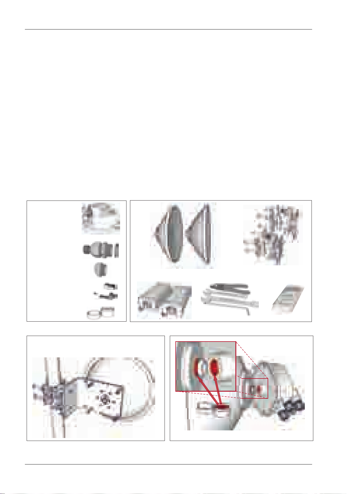
Voltmeter
Antenna brackets
Antennas
Power supply
Required tools
RAy2
Plugs
Grease
Bushings
7×
2×
1×RJ45
1×
1×DC
3×3×
Connectors
Grease
Antenna
RAy2
Mounting
- right sided (pictured below)
- left sided
Quick guide
Quick guide
Accessing units
— Default IP addresses: 192.168.169.169/24 (L unit) Username: admin
192.168.169.170/24 (U unit) Password: admin
Set computer IP address within the IP range 192.168.169.1-255.
— Web browser access – https://192.168.169.169 (L unit)
or https://192.168.169.170 (U unit).
Accept the https security certificate issued by RACOM.
— If the units are linked to each other, the status indicator in management interface states “OK”
and status LED “AIR” lights green. If not, utilize the antenna alignment. (see pict. 11)
Configuration and backup of basic parameters
Set bandwidth, TX/RX channel, TX modulation, RF power, IP addresses (do not use
the default ones), Access channels (ssh, https, …).
Reboot both units and check the link status (to verify that the parameters are saved correctly)
Backup the configuration in the Tools – Maintenance – Backup – Settings menu.
Store the backup file to your PC.
1. Delivered items
3. Bracket and antenna mounting
2. Accessories
4. RAy unit and antenna lubrication
RAy2 Microwave Link – © RACOM s.r.o.8
Page 9
Check the correct O – ring placement
on the antenna
Ensure the antenna and unit are carefully aligned
Do not use excessive force!
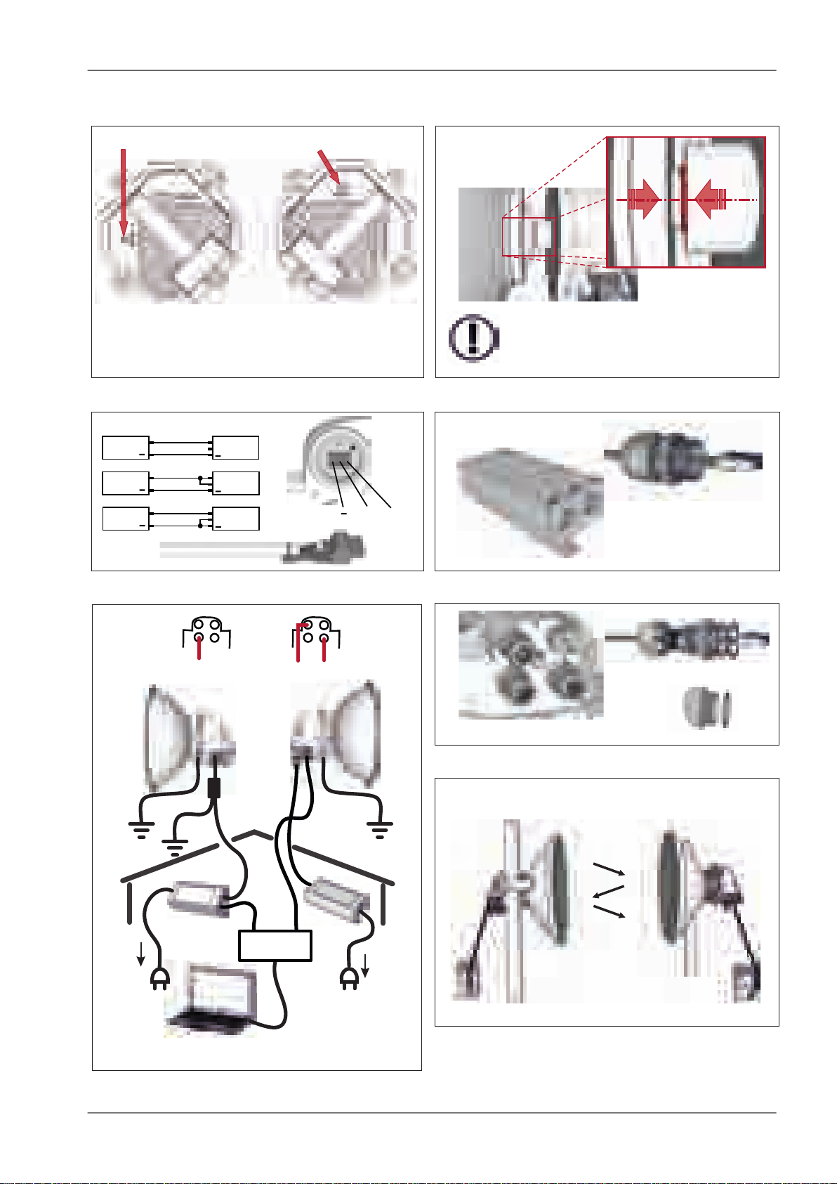
Horizontal
Vertical
- the same polarization
for both units
RAy2-10, RAy2-11
RAy2-17, RAy2-24
- cross polarization
- one side – horizontal
- the other side – vertical
Power supply
RJ45
DC cable
GND
+
+
+
+
DC
DC
DC
+
+
+
RAy2
RAy2
RAy2
GND
GND
GND
Bushing
Plug
Seal unit interfaces with bushings and plugs
AC 230 V
AC 230 V
PoE
PoE + Eth
DC
SWITCH
DC fibre
Units must be grounded
For surge protection - see user manual
Hint: Set QPSK, CS 7 MHz, max. TX power
Best RSS = minimum voltage in range 0–2 V
1
3
2
4
Step-by-step alignment – see user manual
Quick guide
5. Unit polarization
7. Power - DC
6. Unit installation
8. Power - PoE
9. Power grounding and connections
10. Sealing
11. Antenna alignment
ver. 1.7
9© RACOM s.r.o. – RAy2 Microwave Link
Page 10

List of documentation
List of documentation
User manuals
■ Microwave Link RAy2 - this document
User manual RAy2-10, RAy2-11, RAy2-17, RAy2-24
■ Microwave Link RAy11, 17, 24
User manual RAy11, RAy17, RAy24
■ Microwave Link RAy10
2
User manual RAy10
Datasheets
■ RAy2 - Datasheet
■ RAy - Datasheet
■ RAy - SCADA Backbone
3
4
5
Application notes
■ RAy - Application notes
6
Contents of the box
• 2 pc RAy2
1
• 2 pc Cable bushing set, connectors
• 1 pc Grease marked "SILIKONOVE MAZIVO"
1
http://www.racom.eu/eng/products/m/ray17/index.html
2
http://www.racom.eu/eng/products/m/ray/index.html
3
http://www.racom.eu/download/hw/ray/free/eng/00_letaky/datasheet_RAY2_en.pdf
4
http://www.racom.eu/download/hw/ray/free/eng/00_letaky/datasheet_RAY_en.pdf
5
http://www.racom.eu/download/hw/ray/free/eng/00_letaky/leaflet_RAY_scada_en.pdf
6
http://www.racom.eu/download/hw/ray/free/cz/01_ray/RAy-AppNote-en.pdf
RAy2 Microwave Link – © RACOM s.r.o.10
Page 11

RAy2 – Microwave Link
1. RAy2 – Microwave Link
The microwave link RAy2 is designed as a high-speed point-to-point wireless bridge for data transmission
under the latest requirements of modern wireless transmission equipment.
RAy2 works with an ethernet interface and can be used in backhaul networks as well as a last-mile
terminal.The design of microwave link RAy2 reflects effort on meeting the strictest criteria of ETSI
standards, particularly for durability against interference, high receiver sensitivity and high output power
to achieve maximum link distance. The native gigabit Ethernet interface is able to cope with full speed
user data throughput at low latency. High availability of the link (up to 99.999%) is able to be achieved
using hitless Adaptive coding and modulation. RAy2 microwave links can also be operated as a Short
Range Device (SRD).
The link properties can be summarised as:
• High data throughput
• Spectrum effeciency
• Robustness
• Security - cofiguration via http, https, ssh
• User friendly interface, advanced diagnostics
Key technical features see Chapter 10, Technical parameters
Note
Operation of the RAy2-xx is described in this user manual.
Operation of the RAy11, RAy17 and RAy24 is described in User Manual RAy11,17,241.
Operation of the RAy10 is described in the RAy10 User Manual2.
1
http://www.racom.eu/eng/products/m/ray17/index.html
2
http://www.racom.eu/eng/products/m/ray/index.html
11© RACOM s.r.o. – RAy2 Microwave Link
Page 12

Implementation Notes
2. Implementation Notes
2.1. Link calculation
Before a microwave link can be installed, an analysis and calculation of the microwave link must be
made first. The analysis should take place before the site survey itself to get a clear idea about the dimensions of the antennas. The analysis consists of the following steps:
• Free space loss calculation
• Link budget calculation
• Rain attenuation
• Multipath fading
• Fade margin
• Fresnel zones calculation
This chapter explains the individual steps and an example of link design is given at the end.
NOTE - For quick reference you can use the calculator on www.racom.eu
1
2.1.1. Free space loss calculation
As the electromagnetic waves travel through open space they are attenuated. This attenuation is described as Free-space Loss. The loss depends on the distance travelled by signal and its frequency.
Longer distance and higher frequency both mean greater attenuation. Free-space loss can be calculated
thus:
FSL = 32.44 + 20log f + 20log D
Where:
FSL
f
D
free-space loss (dB)
frequency of the emitted signal (MHz)
length of the link (km)
2.1.2. Link budget calculation
The goal is to design a link producing a received signal stronger than the receiver's sensitivity at the
required BER (typically 10-6). Since every radio signal in earth atmosphere is subject to fading, some
difference between received signal level under normal circumstances and receiver sensitivity is needed
to serve as a fade margin. The minimum value of fade margin can be calculated from the requirement
for link availability (e.g. 99.999% of the time). The required margin depends on the length of the link
as well as other factors such as rain attenuation, diffraction and multipath propagation.
If we ignore the additional loss along the path, the received signal strength can be calculated using the
formula for signal propagation in free space as follows:
PR= PT+ GT+ GR- FSL
Where
1
http://www.racom.eu/eng/products/microwave-link.html#calculation_obsah
RAy2 Microwave Link – © RACOM s.r.o.12
Page 13

Implementation Notes
P
P
G
G
FSL
received power level (dBm)
R
transmitted power (dBm)
T
transmitting antenna gain (dBi)
T
receiving antenna gain (dBi)
R
free space loss (dB)
PRmust be:
PR> P
S
Where:
receiver sensitivity (dBm)
P
S
The receiver’s sensitivity defines the minimum level of the received signal at which the receiver is able
to process the signal without losses or affecting the transmitted data (for BER better then 10-6).
2.1.3. Fade margin
Determining sufficient fade margin is the most important step in microwave link design. If the margin
is too small, the link will be unstable – as a result, sufficient availability of the link or quality of the
provided services cannot be guaranteed. On the other hand, unnecessarily large margin makes the
link more expensive (higher performance, larger and more expensive antennas) and increases the
cost of creating the microwave link.
The following paragraphs describe the two most significant types of signal strength loss – rain and
multipath attenuation, which are the most frequent along with free space loss. Mutual relation between
rain and multipath attenuation rules out the possibility that the link could be affected by both types of
attenuation at the same time – these types of attenuation do not add up. To determine the fade
margin it is necessary to calculate both rain and multipath attenuation. The larger of the two types of
attenuation determines the value of fade margin. In areas with high precipitation, rain attenuation can
be expected to be more prominent. By contrast, links located in drier climates and little inclination, will
suffer more from multipath attenuation.
2.1.4. Rain attenuation
For frequencies of about 10 GHz rain attenuation starts to become increasingly effective. Precipitation
is not identical in all areas which is why ITU released a recommendation Rec. ITU-R PN.837-1 for
splitting the world into 15 regions according to precipitation intensity see Fig. 2.1, for more detail Appendix B, Rain zone map. In the areas with higher precipitation greater rain attenuation must be expected
and a greater signal fade margin must be established; see the calculation of link availability.
The following properties are inherent to rain attenuation:
• It increases exponentially with rain intensity
• It becomes significantly larger as the distance travelled increases (>10 Km)
• Horizontal polarization causes greater rain attenuation than vertical polarization
• Rain outage increases dramatically with frequency and path length
13© RACOM s.r.o. – RAy2 Microwave Link
Page 14

Implementation Notes
Fig. 2.1: Rain zone map, based on Rec.ITU-R PN.837-1
Rain attenuation can be calculated using ITU-R outage model, which consists of the following:
Obtain the rain rate R
R
values are defined for 15 rain zones and different time percentages and they are given in ITU-R
0.01
exceeded for 0.01 per cent of the time (with an integration time of 1 min).
0.01
Recommendation P.837.
Tab. 2.1: Rain rate R (mm/h) ITU-R P.837
Percentage
of time (%)
QPNMLKJHGFEDCBA
1412542158231.70.62.10.70.5<0.11.0
4934151174213474.52.44.52.820.80.3
7265352215122010128685320.1
96105654033232818201512139650.03
11514595636042353230282219151280.01
14220014095105704555455441292621140.003
1702501801201501005583657870424232220.001
Compute specific attenuation γR(dB/km) for the frequency, polarization, specific rain rate using ITU-R
recommendation P.838. Rain attenuation for rain rate γ
h,v
γ
= k
R
0.01
h,v.R0.01
α
can be calculated as follows:
R
0.01
where:
RAy2 Microwave Link – © RACOM s.r.o.14
Page 15
Implementation Notes
k
h,v
, α
constants for horizontal and vertical polarization. Constants are slightly different for each
h,v
polarization, see next table according to ITU-R P.838
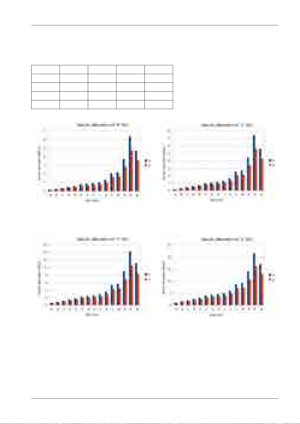
Tab. 2.2: Constants k, α for horizontal and vertical polarization at 10, 11, 17 and 24 GHz
k
h
α
h
Fig. 2.2: Attenuation for 10 GHz,
polarization H, V
k
v
α
v
1.220.011.260.0110 GHz
1.160.021.210.0211 GHz
1.010.071.090.0617 GHz
0.960.141.010.1424 GHz
Fig. 2.3: Attenuation for 11 GHz,
polarization H, V
Fig. 2.4: Attenuation for 17 GHz,
polarization H, V
Fig. 2.5: Attenuation for 24 GHz,
polarization H, V
Fig. 2.2 shows that rain attenuation is greater for horizontal polarization. In regions with higher precipitation the difference in attenuation is more marked. The microwave links RAy17 and RAy24 use both
polarizations, hence the need to consider the worse of the two, i.e. horizontal polarization. When ACM
15© RACOM s.r.o. – RAy2 Microwave Link
Page 16

Implementation Notes
is active we recommend using horizontal polarization in the direction with lower data traffic (typically
up-link).
2.1.5. Multipath fading
Multipath fading is another dominant fading mechanism. A reflected wave causes a phenomenon known
as multipath, meaning that the radio signal can travel multiple paths to reach the receiver. Typically,
multipath occurs when a reflected wave reaches the receiver at the same time in opposite phase as
the direct wave that travels in a straight line from the transmitter.
Multipath propagation gives rise to two kinds of signal degrading effects, i.e., flat fading and frequency
selective fading. Flat fading is a reduction in input signal level where all frequencies in the channel of
interest are equally affected and is dependent on path length, frequency, and path inclination. In addition,
it is strongly dependent on the geoclimatic factor K.
To calculate the probability of outage due to multipath propagation of microwave links the ITU-R
probability model can be used which describes a single frequency (or narrowband) fading distribution
suitable for large fade depths A in the average worst month in any part of the world (based on ITU-R
P.530-14). The calculation for detailed link design is given as follows [1]:
P0= Kd
3.4
(1+|εP|)
-1.03f0.8
0.00067hL-A/10
×10
where:
link distance (km)
d
frequency (GHz)
f
altitude of lower antenna (m)
h
L
fade depth (dB)
A
K is geoclimatic factor and can be obtained from:
K = 10
-4.6-0.0027dN1
The term dN1 is provided on a 1.5° grid in latitude and longitude in ITU-R Recommendation P.453.
The data are available in a tabular format and are available from the Radiocommunication Bureau
(BR). E.g. in Central Europe the values dN1 range from -242 to -362.
From the antenna heights heand hr(meters above sea level), calculate the magnitude of the path inclination │εP│ (mrad) using the following expression:
where:
d
hr, h
e
link distance (km)
antenna heights above sea level (m)
RAy2 Microwave Link – © RACOM s.r.o.16
Page 17
aaaaa
a
aaaaa
a
aaaaa
a
aaaaa
a
aaaaa
a
aaaaa
a
aaaaa
a
aaaaa
a
aaaaa
a
aaaaa
a
aaaaa
a
aaaaa
a
aaaaa
a
aaaaa
a
aaaaa
a
aaaaa
a
aaaaa
a
aaaaa
a
aaaaa
a
aaaaa
a
aaaaa
a
aaaaa
a
r
D
F
1
d
1
× ×
Implementation Notes
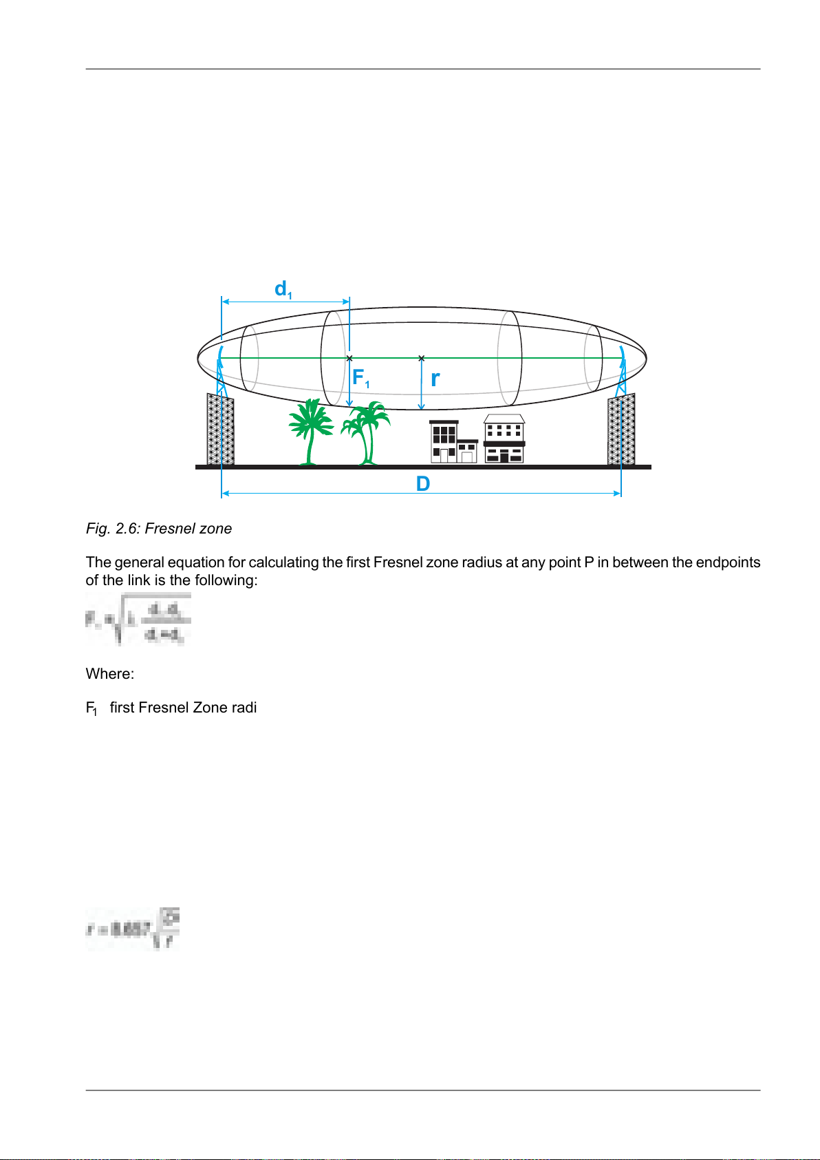
2.1.6. Fresnel zones calculation
The position of obstacles between points of the bridge can significantly influence the quality of the microwave link. The radio signal doesn't only radiate along the line of sight, but also in the area around
it, i.e. in the so-called 1st Fresnel zone. Within this zone 90 % of the energy is transmitted between the
transmitter and receiver antenna. This space has the shape of an ellipsoid. If it is disturbed the link has
poorer transmission properties and a higher quality antenna is required. For this reason the position
of the antenna can be just as important as its height above ground. 60 % of the 1st Fresnel zone is
considered as the most important.
Fig. 2.6: Fresnel zone
The general equation for calculating the first Fresnel zone radius at any point P in between the endpoints
of the link is the following:
Where:
F1first Fresnel Zone radius in metres
d1distance of P from one end in metres
d2The distance of P from the other end in metres
λ wavelength of the transmitted signal in metres
The cross sectional radius of each Fresnel zone is the highest in the center of link, shrinking to a point
at the antenna on each end. For practical applications, it is often useful to know the maximum radius
of the first Fresnel zone. From the above formula, calculation of the first Fresnel zone can be simplified
to:
where:
max radius of first Fresnel zone (m)
r
reducing the radius to 60% get values listed in the following table that define the space particularly
sensitive to the presence of obstacles
17© RACOM s.r.o. – RAy2 Microwave Link
Page 18
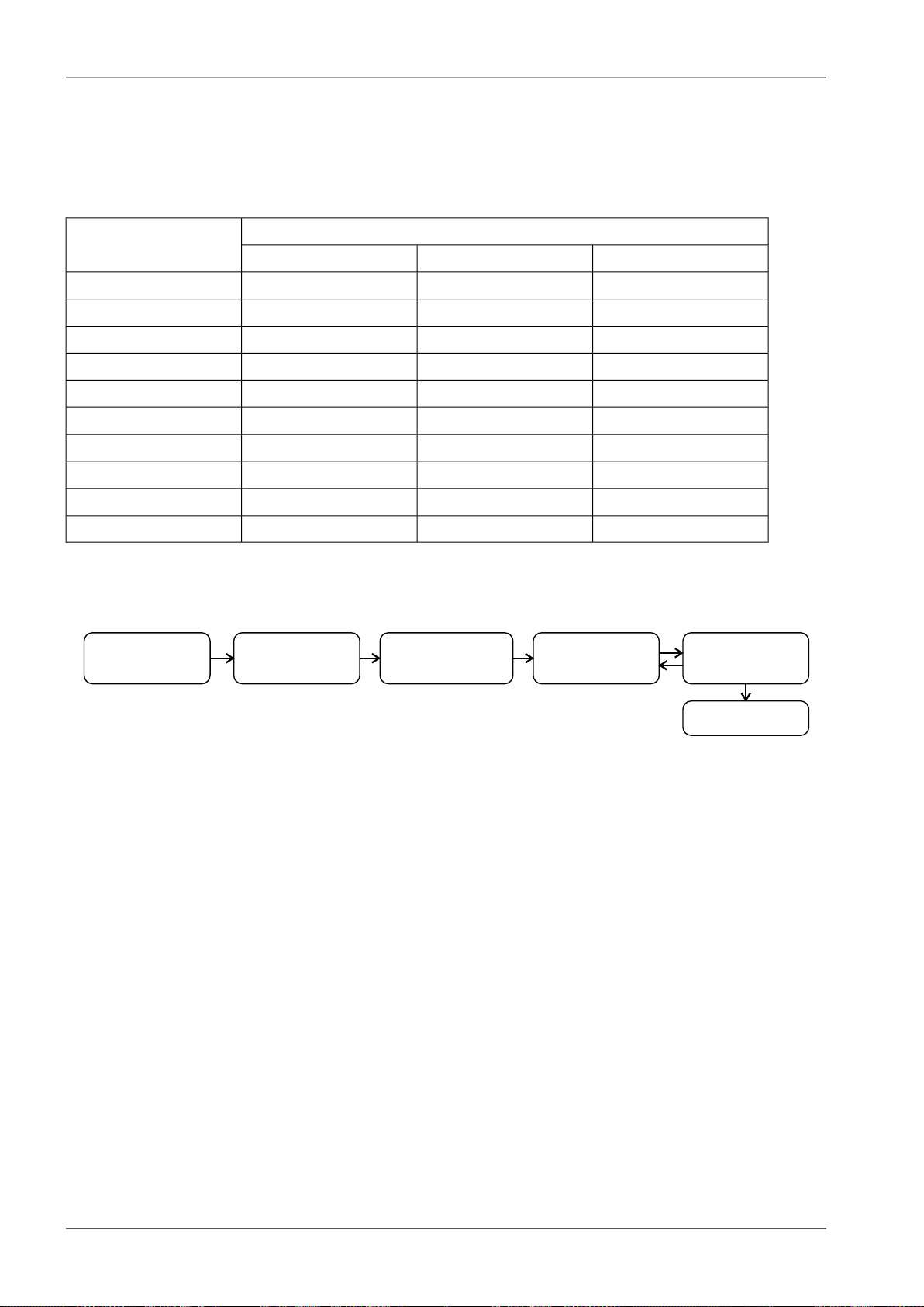
Stanovení
požadavků
Výpočet ú tlumu při
šíření prostorem
Výpoštčet ú niku
vlivem de ě a
vícecestným šířením
Volba vysílacího
výkonu antén
Kalkulace spoje
Výsledek
1. 2. 3. 4. 5.
Implementation Notes
total link distance (km)
D
frequency (GHz)
f
Tab. 2.3: 60 % of the 1st Fresnel zone
Radius of zone r for frequencyLength of link D
24 GHz17 GHz11 GHz
0.75 m0.89 m1.10 m0,5 km
1.06 m1.25 m1.56 m1 km
1.50 m1.77 m2.21 m2 km
2.12 m2.50 m3.13 m4 km
2.60 m3.07 m3.84 m6 km
3.00 m3.54 m4.43 m8 km
3.35 m3.96 m4.95 m10 km
4.10 m4.85 m6.06 m15 km
4.74 m5.60 m7.00 m20 km
11.07 m50 km
2.2. Example of microwave link design
Fig. 2.7: Design flowchart
Step 1 - Requirements Determination
Link parameters:
Link distance: 4 km
First antenna height above sea level: 295 m
Second antenna height above sea level: 320 m
Location: Central Europe (rain zone H, refraction gradient dN1= −300)
Transmission requirements:
Required data rate: >160 Mbps
Required availability: 99.99 %
RAy parameters:
17 GHz
161 Mbps -> Modulation 16QAM; BW=56 MHz; PS(BER 10-6)= −79 dBm
Tx power +5 dBm (max. Tx power)
Antenna gain:
RAy2 Microwave Link – © RACOM s.r.o.18
Page 19

30 cm ... 32.2 dBi
60 cm ... 37.8 dBi
99 cm ... 42 dBi
Step 2 - Free space loss calculation
FSL = 32.44 + 20log f + 20log D = 32.44 + 20log17.2·103+ 20log4 = 129.1 dB
Step 3a - Rain attenuation
Implementation Notes
For 99.99% availability in rain zone B the rain rate is R
=32 (see Fig. 2.1)
0.01
For f=17 GHz kh=0.06146; αh=1.0949; kv=0.06797; αv=1.0137
Vertical polarization:
γ
R0.01
= kv.R
α
v
0.01
= 0.07 · 32
1.01
= 2.32 dB/km => for 4km distance 9.3 dB
Horizontal polarization:
γ
R0.01
= kh.R
α
h
0.01
= 0.06 · 32
1.09
= 2.62 dB/km => for 4km distance 10.5 dB
Step 3b - Attenuation due to multipath propagation
We have to find required fade margin for reliability of the link 99.99 percent.
Path inclination:
The percentage of time that fade depth A (dB) is exceeded in the average worst month is calculated
as:
P0= Kd
P0= 10
3.4
(1+|εP|)
-4.6-0.0027×(-300)×43.4
P0= 0.022871×10
-1.03f0.8
×10
-0.19765-A/10
0.00067hL-A/10
(1+|6.25|)
-1.03
17.2
0.8
0.032×10-0.00067×295-A/10
×10
For reliability 99.99% is P0=0.01 we get exponential function for A:
A = -0.19765 - 10log(0.01/0.022871) = 3.4 dB
The minimum fade margin required to suppress multipath fading on this link would be 4 dB.
Step 4 - Choice of Tx power and antennas
Step 5 - and Link budget calculation
Calculation in steps 3a and 3b determines the minimum fade margin required for stable link operation
as 11 dB (rain attenuation is dominant). If you use the maximum performance of antenna with diameter of 30 cm, complete the radio formula as follows:
PR= PT+ GT+ GR− FSL = 5 + 32.2 + 32.2 − 129.1 = −59.7 dB
Fade margin:
A = |PS| − |PR| = 79 − 59.7 = 19.3 dB
The resulting fade margin is larger than the required 11 dB. Current legislation in the Czech Republic
allows maximum EIRP of +20, i.e. the sum of transmit power and antenna gain at the transmitter
can be 20 dB at the most. For 99cm antennas, TX power can be up to 20 - 42 = -22 dB, the resultant
equation is as follows:
PR= PT+ GT+ GR− FSL = -22 + 42 + 42 − 129.1 = −67.1 dB
19© RACOM s.r.o. – RAy2 Microwave Link
Page 20

Implementation Notes
Fade margin:
A = |PS| − |PR| = 79 − 67.1 = 11.9 dB
Fade margin is now only 12 dB which corresponds to link availability > 99.99% of the time in a year.
Technical literature often gives the minimum fade margin of 20 dB. For very long links (more than
10 km) fade margin will, indeed, be approximately 20 dB. For shorter links, however, such large
margin is not necessary. It is helpful to first conduct the calculation above to receive an idea of the
attenuation affecting the link.
The result
To achieve the required transmission capacity and link availability for link distance of 4 km, transmit
power -22 dBm and 99 cm antennas were selected for both sides of the link.
Sources for Chapter Chapter 2, Implementation Notes:
[1] Lehpamer, H.: Microwave transmission network, Second edition, ISBN: 0071701222, McGraw-Hill
Professional, 2010.
ITU-R recommendation used:
• ITU-R P.453-10 – The radio refractive index: its formula and refractivity data
• ITU-R P.530-14 – Propagation data and prediction methods required for the design of terrestrial
line-of-sight systems
• ITU-R P.837-1 and 6 – Characteristics of precipitation for propagation modelling
• ITU-R P.838-3 – Specific attenuation model for rain for use in prediction methods
• ITU-R P.310, ITU-R P.526, ITU-R P.676, ITU-R P.834, ITU-R P.835
RAy2 Microwave Link – © RACOM s.r.o.20
Page 21
Product
3. Product
RAy2 microwave links enable transmissions in both bands requiring license fees and those that are
free. They work as a point-to-point link in a full duplex setting with transfer speeds of up to 360 Mbps.
Bandwidth can be configured from 1.75 up to 56 MHz. Modulation can be fixed or adaptive and can
be adjusted from QPSK to 256QAM. RAy2 microwave links can also be operated as a Short Range
Device (SRD).
Fig. 3.1: RAy2 – Microwave link
The link is formed by two FOD (Full Outdoor) units. In the case of links operating in the RAy2-17 and
RAy2-24 bands, both units have identical hardware. In the case of links operating in licensed bands,
one unit (labeled L) is transmitting in the Lower and receiving in the Upper part of the band. The other
unit (labeled U) is operating vice versa.
RAy2 links require the use of external parabolic antennas. Parabolic antennas from different producers
are available.
Cross polarization - valid only for links operating in the RAy2-17 and RAy2-24 bands:
One side of the link uses one polarization for transmission (e.g. horizontal) and the opposite polarization
for receiving (e.g. vertical). The other side of the link is turned by 90°. It therefore transmits and receives
using opposite polarizations with respect to the other unit.
21© RACOM s.r.o. – RAy2 Microwave Link
Page 22
Product
3.1. Mounting
Fig. 3.2: RAy2 Microwave link – antenna and FOD unit
The antenna is attached to the mast using a holder adjustable in two planes. The RAy2 unit is then
mounted on the antenna.
There are two possible mounting positions – for horizontal and vertical polarization. Installation and
adjustment of the holder is described in the Section 6.2, “Antenna mounting”.
Note
The RAy2-10 and RAy2-11 units must be mounted with the same polarization while the
units RAy2-17 and RAy2-24 must be mounted with reverse polarity, see Cross polarization.
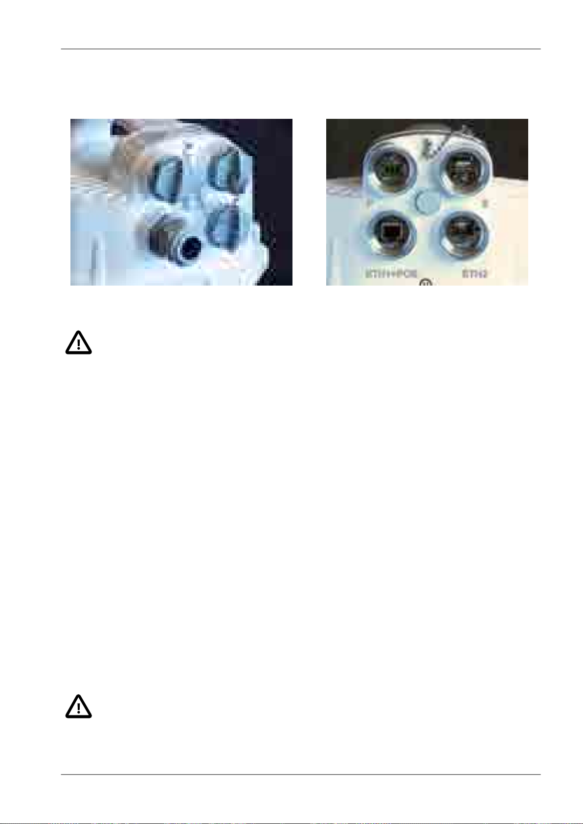
3.2. Connectors
Each unit is equipped with the following interfaces:
■ ETH1+POE – Gigabit metallic Ethernet port. This port is capable of powering the unit with any
Power over Ethernet power source working according to IEEE 802.3at standard.
■ ETH2 – Slot for user exchangeable SFP module. A wide range of optical modules is available. Both
single or dual mode transceivers can be used. An SFP module with metallic RJ45 interface can
also be used.
The SFP status LED is located just next to the slot.
■ P – DC power connector.
HW button for service purposes.
■ S – USB service connector.
RSS voltage output connectors.
Important
It is strongly recommended to use a high quality SFP module. The SFP modules listed in
Accessories are thoroughly tested by RACOM and are guaranteed to function with RAy2
units. It is possible to use any other SFP module, but RACOM cannot guarantee they will
be completely compatible with RAy2 units.
RAy2 Microwave Link – © RACOM s.r.o.22
Page 23
Product
The SFP status LED function: The LED status is controlled directly from the SFP module. Its function
is specific for each SFP module. The typical behaviour is an indication of the received signal strength.
Should the signal be in the proper power range (not too strong and not too weak), the LED is shining.
Fig. 3.3: Connectors covered Fig. 3.4: Connectors uncovered
Important
It is recommended that the ETH cable should be grounded at both ends of the connection.
For example, the connector CON-RJ45-UBNT-CAT6 and ETH socket on the control panel
should have a grounded sheath as should the connection to the RAy2 unit.
All bushings and plugs (including the original plugs in the ports) must be fitted with O-rings
and carefully tightened. Otherwise, the unit is not protected against moisture intake and can
not offer guaranteed functionality.
For detailed description see Connectors and Start up.
3.3. Power supply
The microwave unit can be powered either by PoE or a DC power source:
• Standard PoE plus (IEEE 802.3at) power source connected to the “ETH1+POE” connector.
Supported voltage range is 40 — 60 V, distances up to 100 m. Internal RJ45 pins wiring is :
○ (V+) ... 1,2,4,5
○ (V-) ... 3,6,7,8
It is possible to use all 8 pins or only 4 pins. Use:
○ either 4,5 (V+) and 7,8 (V-)
○ or 1,2 (V+) and 3,6 (V-)
○ or both simultaneously
• Any kind of DC power source connected to “P” 3-pin connector.
Supported voltage range is 20 — 60 V.
Important
The microwave unit doesn't support a combination of both power supplies. Only one power
supply can be connected at any one time.
23© RACOM s.r.o. – RAy2 Microwave Link
Page 24
+
DC
+
RAy2
GND
+
DC
+
RAy2
GND
+
DC
+
RAy2
GND
+
DC
+
RAy2
GND
+
DC
+
RAy2
GND
GND
+
HW button
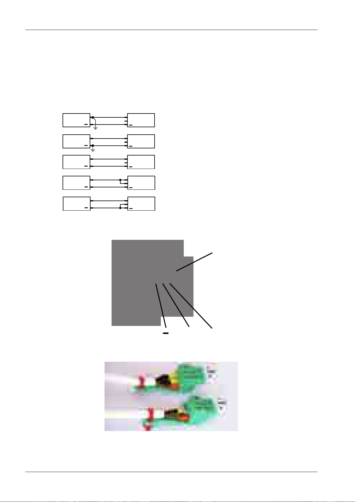
Product
The internal DC power source uses galvanic separation. If the galvanic separated power source is
used and the DC power line needs to be grounded (either positive or negative wire), the middle pin of
the 3-port DC connector can be used to make a connection between ground and the respective power
wire, see Grounding options (d),(e). If grounding is required it should only be made in one of the following
ways: on the DC power source side or using the 3-port DC connector plugged into the unit.
The next figure shows all available grounding options. We recommend the use of a galvanic separated
power source and no additional DC grounding - see Fig. 3.5, “Grounding options” version c).
a)
b)
c)
d)
e)
Fig. 3.5: Grounding options
Fig. 3.6: Power supply connector 1
Fig. 3.7: Power supply connector 2
RAy2 Microwave Link – © RACOM s.r.o.24
Page 25

3.4. Status LEDs
Fig. 3.8: Status LEDs
Tab. 3.1: Meaning of LED status indicators
FunctionColourDiode
Product
AIR
Green
SYS
Red
Green
ETH
Orange
Flashing regularly 500 ms on / 500 ms off
Flashing intermittently 50 ms on / 950 ms off
Flashing irregularly by passing frames
Permanently lit: AIR link OKGreen
Permanently lit: AIR LOSS, loss of connectivityRed
Permanently lit: system OK
Permanently lit: together with SYS Red - unit is starting
Flashing regularly: HW button pushed on the unit running;
factory defaults in progress;
Firmware writing in progress. DO NOT POWER OFF !!
Permanently lit: together with SYS Green - unit is starting;
serious system error
Flashing regularly: HW button just pressed
Flashing intermittently: unit in the service Linux
ETH1 port
Flashing regularly: Auto Negotiation in progress
Flashing irregularly: Link Activity 10/100/1000
Permanently lit: Link 10/100/1000
ETH2 port
Flashing regularly: Auto Negotiation in progress
Flashing irregularly: Link Activity 10/100/1000
Permanently lit: Link 10/100/1000
3.5. Technical parameters
Basic technical parameters are stated in chapter Technical parameters.
25© RACOM s.r.o. – RAy2 Microwave Link
Page 26
S/N: 10218446
Type:
RAy2-24
Code:
RAy2-24
TX/RX: 24.000-24.250 GHz/24.000-24.250 GHz
PoE IEEE 802.3at www.racom.eu
20-60V max.1.5A Made in Czech Republic
Product
3.6. Dimensions
Communication unit ODU
Outer size 244 x 244 x 157 mm•
Weight RAy2-10 — 2.8 kg•
• RAy2-11 — 2.8 kg
• RAy2-17 — 2.5 kg
• RAy2-24 — 2.5 kg
Diameters of supplied antennas
RAy2 units are ready for direct mounting to Jirous1Class 2 antennas.
Individual datasheets are accessible here2.
Tab. 3.2: Overview of antennas
24 GHz17 GHz10, 11 GHz
gaindiametergaindiametergaindiameter
36.8 dBi40 cm34.8 dBi40 cm29.0 dBi38 cm
41.7 dBi68 cm38.6 dBi68 cm35.5 dBi65 cm
44.0 dBi90 cm41.0 dBi90 cm37.5 dBi90 cm
46.6 dBi120 cm43.7 dBi120 cm41.0 dBi120 cm
Andrew (Class 2 or 3) or Arkivator antennas can also be used but require an antenna mounting kit.
Flexible waveguide is a general-purpose option for any antenna usage.
Name plate
The plate contains name, bar code record, CE label, etc.:
• Type – RAy2 product line identification
• Code – detailed identification of the unit type (for details see Section 3.7, “Ordering codes”)
• S/N – serial number, MW link consists of two separated units with two different serial numbers
• QR code - www link to the latest version of the User manual
• Power DC supply connector polarity marks
Fig. 3.9: Name plate
1
http://en.jirous.com/
2
http://www.racom.eu/eng/products/microwave-link.html#accessories_jirous
RAy2 Microwave Link – © RACOM s.r.o.26
Page 27

Type
Frequency Ordering code
Lower [GHz] Upper [GHz] Lower unit Upper unit
10 GHz
10.30 – 10.42 10.47 – 10.59
RAy2-10-LA RAy2-10-UA
10.125 – 10.325 10.475 – 10.675
RAy2-10-LB RAy2-10-UB
11 GHz
10.695 – 10.970 11.185 – 11.460
RAy2-11-LA RAy2-11-UA
10.935 – 11.195 11.425 – 11.695
RAy2-11-LB RAy2-11-UB
17 GHz 17.100 – 17.300
RAy2-17
18 GHz
1)
17.700 – 18.209 18.710 – 19.219
RAy2-18-LA RAy2-18-UA
18.167 – 18.690 19.177 – 19.700
RAy2-18-LB RAy2-18-UB
24 GHz 24.000 – 24.250
RAy2-24
ver 5.0
1) RAy2-18 not available yet
The
Feature keys
ordering code consists of three parts:
RAy2-
SW- 360
Product type RAy2
Feature key type.
The "SW" key is available now. This key unlocks the User speed to a given value.
The default user speed without the feature key is the minimum for the respective HW unit.
Feature key value. In case of User speed it states Mbps. Possible values 200, 360.
Product
3.7. Ordering codes
The proper pair (from the same row) of Lower and Upper units should be selected when ordering the
microwave link. This is not valid for RAy2-17 and RAy2-24 units. In such a case the same unit is used
for both sides of the link.
Tab. 3.3: Ordering codes
SW key possibilities, valid for RAy2-10, 11, 17, 18, 24:
• RAy2-SW-200 SW feature key - Capacity up to 200 Mbps
• RAy2-SW-360 SW feature key - Capacity up to 200 Mbps
• RAy2-SW-200-360 SW feature key - Capacity upgrade from 200 to 360 Mbps
27© RACOM s.r.o. – RAy2 Microwave Link
Page 28

Accessories
4. Accessories
4.1. Overview
Antenna Jirous
Short descriptionRACOM-PART-NUMBER
Antenna parabolic 0.38 m 10-11GHz with holder 28.0-29.0 dBi Class 2ANT-JRMA-380-10/11R
Antenna parabolic 0.65 m 10-11GHz with holder 34.1-35.5 dBi Class 2ANT-JRMA-650-10/11R
Antenna parabolic 0.9 m 10-11GHz with holder 37.0-37.5 dBi Class 2ANT-JRMB-900-10/11R
Antenna parabolic 1.2 m 10-11GHz with holder 40.0-41.0 dBi Class 2ANT-JRMB-1200-10/11R
Antenna parabolic 0.4 m 17 GHz with holder 34.8 dBi Class 2ANT-JRMB-400-17R
Antenna parabolic 0.68 m 17 GHz with holder 38.6 dBi Class 2ANT-JRMB-680-17R
Antenna parabolic 0.9 m 17 GHz with holder 41.0 dBi Class 2ANT-JRMB-900-17R
Antenna parabolic 1.2 m 17 GHz with holder 44.6 dBi Class 2ANT-JRMB-1200-17R
Antenna parabolic 0.4 m 24 GHz with holder 36.8 dBi Class 2ANT-JRMB-400-24R
Antenna parabolic 0.68 m 24 GHz with holder 41.7 dBi Class 2ANT-JRMB-680-24R
Antenna parabolic 0.9 m 24 GHz with holder 44.0 dBi Class 2ANT-JRMB-900-24R
Antenna parabolic 1.2 m 24 GHz with holder 46.6 dBi Class 2ANT-JRMB-1200-24R
Antenna mounting kit
Set mouting RAy10/11 Antenna Andrew 60, 100SET-RAY10-ANW
Set mouting RAy10/11 Antenna Arkivator 30, 60, 99, 120SET-RAY10-ARK
Set mouting RAy17 Antenna Andrew 30, 60, 100SET-RAY17-ANW
Set mouting RAy17 Antenna Arkivator 30, 60, 99SET-RAY17-ARK
Set mouting RAy24 Antenna Andrew 30, 60, 100SET-RAY24-ANW
Set mouting RAy24 Antenna Arkivator 30, 60, 99, 120SET-RAY24-ARK
Flexible waveguide mounting kit
Set mouting RAy2 to flange R100SET-RAY-FX-R100
Set mouting RAy2 to flange R120SET-RAY-FX-R120
Cable bushing
Basic set cable bushings and connectorsSET-RAY2-CON-B
Cable bushing lengthening, PG21, 35 mmSET-RAY2-EXT35
Cable bushing lengthening, PG21, Flexi, 50cmSET-RAY2-EXT-F50
Power supply DC
Power supply PoE
Power supply holder
Surge protection
Power supply 90-260 VAC / 50 W at 27.6 VDC MeanWellPWS-AC/DC-AD-55B
Power supply PoE 1xGb Eth 90-264 VAC/ 33.6 W at 56 VDC PhihongPWR-POE36U-1AT
Power supply PoE 1xGb Eth 36-72 VDC/ 33.6 W at 56 VDC PhihongPWR-POE36D-1AT
DIN rail holder for PoE PhihongHOL-POE-PHI-1A
RAy2 Microwave Link – © RACOM s.r.o.28
Page 29

Surge protection 1Gb Eth Cat.6 LPZ0B-LPZ1 IP20 -40/+85°COTH-DL-1GRJ45
Surge protection 1Gb Eth Cat.6 LPZ2-LPZ3 IP20 -40/+85°COTH-DL-CAT.6-60V
CAT5e, CAT7 cable
Double shell outdoor FTP Cat5e cable TELDORCAB-CAT5E-FTP-TLD
Double shell outdoor FTP Cat7 cable PEWTRONICCAB-S/FTP 4x
CAT6 connector
Connector TC-CON, STP RJ45, Cat6, 8p8c, wire, pleated, AWG24, UBNTCON-RJ45-UBNT-CAT6
Set RJ45 connector (Telegärtner) and cable bushing lengthening (35mm)SET-RAY2-TLG-EXT35
SFP module RJ45
SFP module, RJ45 interface, -40°C to +85°C , AvagoSFP-RJ45-AVAGO
SFP module optical
SFP module, 2-fibres, LC, 10km, -40°C to +85°C, APAC OptoSFP-DLC-APAC
Fibre cable patchcord/pigtail
Accessories
CAB-FIB-2F-DLC/DLC-OFA5m
CAB-FIB-1F-LC/LC-OFA-5m
DC & Fibre cable patchcord
OFA-030m
DC cable
DC surge protection
RAy grounding kit
Access adapters
Fibre patch cord, 2-fibres, single mode, LC-connector — LC-connector,
OFA, 5 m
Fibre patch cord, 1-fibre, single mode, LC-connector — LC-connector,
OFA, 5 m
Fibre pigtail, 2-fibres, single mode, LC-connector — loose end, OFA, 5 mCAB-FIB-2F-DLC/x-OFA-5m
Fibre pigtail, 1-fibre, single mode, LC-connector — loose end, OFA, 5 mCAB-FIB-1F-LC/x-OFA-5m
DC power cable - Fibre: patchcord, 2-fibresCAB-HYB-2F-DLC/DLC-
DC power cable 2x1.5 mm, silicone rubberCAB-DC-2x1.5
Overvoltage protection, DC 24V, LPZ1-LPZ2, IP20, -40/+85°C , SaltekOTH-DP-024
Grounding kit for antenna cableKIT-GROUDING-1/4"
Grounding kit for mast groundingKIT-GROUDING-RAY
Wifi adapterOTH-W1-WIFI
Ethernet adapterSET-X5-ETH/USB
29© RACOM s.r.o. – RAy2 Microwave Link
Page 30
Accessories
4.2. Details
Antenna
The overview of different Jirous antenna types is listed in Section 3.6,
“Dimensions”. The antenna choice determines radio link properties.
The radio link calculation should be performed to determine proper
antenna size. Rough calculation can be done using a simple on-line
calculator.
1
• see the Overview
• List of datasheets
2
Antenna mounting kit
Other manufacturer's antennas can also be used with RAy2 links.
The RAy2 unit can be attached by means of special interconnetions.
There are several types of these parts for Andrew and Arkivator
antennas. It is also possible to develop interconnetions for other
antenna types.
• see the Overview
• The bracket for mounting FOD unit on the antenna.
Flexible waveguide mounting kit
The RAy2 unit can be attached to the antenna by flexible waveguide.
• SET-RAY-FX-R100
• SET-RAY-FX-R120
• The bracket for mounting the flexible waveguide on the FOD
unit.
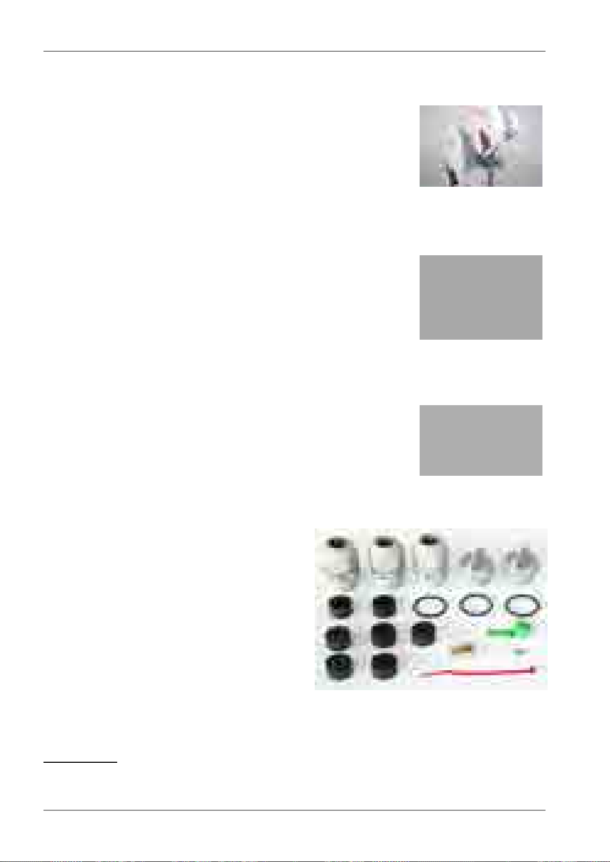
Cable bushing
• SET-RAY2-CON-B
• Basic set cable bushings and connectors
contains:
○ 3 pc standard PG21 bushing with nut
○ 2 pc blind plug Racom
○ 3 pc O-ring
○ 2 pc rubber sealing small diameter
○ 3 pc rubber sealing medium diameter
○ 2 pc rubber sealing big diameter
○ 1 pc DC connector
○ 1 pc tie wrap
○ 1 pc connector jumper
○ 1 pc RJ-45 ethernet connector
1
http://www.racom.eu/eng/products/microwave-link.html#calculation
2
http://www.racom.eu/eng/products/microwave-link.html#accessories
RAy2 Microwave Link – © RACOM s.r.o.30
Page 31

• SET-RAY2-EXT35
• Cable bushing lengthening, PG21, 35 mm
• O-ring
• SET-RAY2-EXT-F50
• Cable bushing lengthening, PG21,Flexi, 50cm
• orig. part no: LPA6-23N-0.5m,RKG-23P21N,
RKF-23P21N, 2xORC-23, flat ring FSN-P21
Power supply DC
• PWS-AC/DC-AD-55B
• orig. part no: AD-55B
• FOD unit power supply 50 W, 24 V, UPS Function, MeanWell
• Datasheet
3
Accessories
Power supply PoE
• PWR-POE36U-1AT
• orig. part no: POE36U-1AT
• FOD unit power supplies – 30 W PoE adapters, 1x Eth
• Input 100 to 240 VAC, Output 56 V / 33.6 W, Phihong
• Datasheet AC
4
• PWR-POE36D-1AT
• orig. part no: POE36D-1AT
• Input 36 to 72 VDC / 1.2 A, Output 56 V / 33.6 W, Phihong
• Datasheet DC
5
Power supply holder
• HOL-POE-PHI-1A
• 1x Eth PoE power supply, DIN rail mountable
3
http://www.racom.eu/download/hw/ray/free/eng/07_prislusenstvi/PWS-AC-DC-AD-55B.pdf
4
http://www.racom.eu/download/hw/ray/free/eng/07_prislusenstvi/PWR-POE36U-1AT.pdf
5
http://www.racom.eu/download/hw/ray/free/eng/07_prislusenstvi/PWR-POE36D-1AT.pdf
31© RACOM s.r.o. – RAy2 Microwave Link
Page 32

Accessories
Surge protection
• OTH-DL-1GRJ45
• orig. part no: DL-1GRJ45
• Protection from the voltage spikes
• Datasheet
6
• OTH-DL-CAT.6-60V
• orig. part no: DL-Cat. 6-60 V
• Datasheet
7
CAT5e cable
• CAB-CAT5E-FTP-TLD
• orig. part no: PLU030078
• Cat.5e cable for connecting FOD units to the network, TELDOR
• Datasheet
8
CAT7 cable
• CAB-S/FTP 4x
• orig. part no: S / FTP 4x (2x23AWG) Cat.7 + 2x (2×24 AWG)
• Cat.7 cable for connecting FOD units to the network,
PEWTRONIC Ltd.
• Datasheet
9
6
http://www.racom.eu/download/hw/ray/free/eng/07_prislusenstvi/OTH-DL-1GRJ45.pdf
7
http://www.racom.eu/download/hw/ray/free/eng/07_prislusenstvi/OTH-DL-CAT-6-60V.pdf
8
http://www.racom.eu/download/hw/ray/free/eng/07_prislusenstvi/CAB-CAT5E-FTP-TLD.pdf
9
http://www.racom.eu/download/hw/ray/free/eng/07_prislusenstvi/CAB-SFTP-4x.pdf
RAy2 Microwave Link – © RACOM s.r.o.32
Page 33

CAT6 connector
• CON-RJ45-UBNT-CAT6
• orig. part no: TC-CON connector STP RJ45
STP RJ45 /Cat6 / 8p8c / wire/ gold plated/ AWG24, UBNT
• SET-RAY2-TLG-EXT35
• orig. part no: Telegärtner MFP8 Cat.6A AWG 22-27
Connector RJ45, Cat6A, AWG 24-22, Telegärtner
+ Racom SET-RAY2-EXT35
• Set RJ45 connector (Telegärtner) and cable bushing lengthening
(35mm). Suitable for AWG24-22 (Cat5e, Cat6A, Cat7) cables.
• Datasheet
10
SFP module RJ45
• SFP-RJ45-AVAGO
• orig. part no: ABCU-5730ARZ
SFP module, RJ45 interface, -40°C to +85°C , Avago
• Datasheet
11
Accessories
SFP module optical
• SFP-DLC-APAC
• orig. part no: LS38-C3S-TI-N-DD
SFP module, 2-fibres, LC, 10km, -40°C to +85°C, APAC Opto
• Datasheet
12
Fibre cable - outdoor patchcord / outdoor pigtail
• CAB-FIB-2F-DLC/DLC-OFA-5m
• orig. part no: DLCRAC2Fyyy
patchcord, 2-fibres,single mode, LC-connector — LC-connector,
yyy meters, OFA
• CAB-FIB-1F-LC/LC-OFA-5m
• orig. part no: LCRAC1Fyyy
patchcord, 1-fibre, single mode, LC-connector — LC-connector,
yyy meters, OFA
10
http://www.racom.cz/download/hw/ray/free/eng/07_prislusenstvi/SET-RAY2-TLG-EXT35.pdf
11
http://www.racom.cz/download/hw/ray/free/eng/07_prislusenstvi/SFP-RJ45-AVAGO.pdf
12
http://www.racom.eu/download/hw/ray/free/eng/07_prislusenstvi/SFP-DLC-APAC.pdf
33© RACOM s.r.o. – RAy2 Microwave Link
Page 34

Accessories
• CAB-FIB-2F-DLC/x-OFA-5m
• orig. part no: DLC0RAC2Fyyy
pigtail, 2-fibres, single mode, LC-connector — loose end,
yyy meters, OFA
• CAB-FIB-OFA-1F-LC/x-OFA-5m
• orig. part no: LC0RAC1Fyyy
pigtail, 1-fibre, single mode, LC-connector — loose end,
yyy meters, OFA
• Datasheet
13
Fibre & DC outdoor cable
• CAB-HYB-2F-DLC/DLC-OFA-030m (example for 30m long cable)
• orig. part no: DLCHRAC2Fyyy Phoenix Microwave Hybrid Cable LSOH, yyy meters, OFA
DC: 2x1.5mm2; fibre: patchcord, 2-fibres, single mode, LC-connector — LC-connector
• Datasheet
14
DC cable
• CAB-DC-2x1.5
• orig. part no: V05SS-F 2Dx1.50
silicone rubber, 2x1.5 mm², -40 to +60°C, ProPS
• Datasheet
15
DC surge protection
• OTH-DP-024
• orig. part no: DC 24V
LPZ1-LPZ2, IP20, -40/+85°C , Saltek
• Datasheet
16
13
http://www.racom.eu/download/hw/ray/free/eng/07_prislusenstvi/CAB-FIB-OFA.pdf
14
http://www.racom.cz/download/hw/ray/free/eng/07_prislusenstvi/CAB-HYB-OFA.pdf
15
https://webservice-new.racom.eu/main/eshop.detail?i=193
16
http://www.racom.eu/download/hw/ray/free/eng/07_prislusenstvi/OTH-DP-024.pdf
RAy2 Microwave Link – © RACOM s.r.o.34
Page 35

RAy grounding kit
• KIT-GROUDING-1/4"
• Grounding kit for Cat.7 S/FTP 4x(2x23 AWG) cable. Pewtronic.
• Detail see Grounding.
• Datasheet
17
• KIT-GROUDING-RAY
• RAy grounding set for grounding RAy equipment to the mast.
Contains a ZSA16 grounding terminal, grounding tape and a
cable with grounding lugs.
• Detail see Grounding.
• Datasheet
18
Access adapters
• OTH-W1-WIFI
• Wifi adapter for service access to the web interface via USB
connector. RAy2 provides a built-in DHCP server with up to 6
leases. To access the RAy2 always use the fixed IP
169.254.169.168 (Lower Unit) or 169.254.170.168 (Upper Unit).
Accessories
• SET-X5-ETH/USB
• Ethernet adapter for service access to the web interface via USB
connector. RAy2 provides a built-in DHCP server with up to 6
leases. To access the RAy2 always use the fixed IP
169.254.169.168 (Lower Unit) or 169.254.170.168 (Upper Unit).
Extended descriptions
See www.racom.eu, Microwave link, Accessories
19
E-shop
Accessories easiest to order here:
E-shop RACOM
Use there a search engine Ctrl+F and RACOM-PART-NUMBER of the searched item.
20
17
http://www.racom.eu/download/hw/ray/free/eng/07_prislusenstvi/KIT-GROUDING-RAY.pdf
18
http://www.racom.eu/download/hw/ray/free/eng/07_prislusenstvi/ZSA16-en.pdf
19
http://www.racom.eu/eng/products/microwave-link.html#accessories
20
https://webservice-new.racom.eu/main/eshop.list?a=1&t=10
35© RACOM s.r.o. – RAy2 Microwave Link
Page 36

Step-by-step Guide
5. Step-by-step Guide
The following chapters will guide you step by step through preparation, installation and activation of
the RAy2 link:
• Pre-installation check out
•
Installation (Chapter 6, Installation)
•
Advanced configuration (Chapter 7, Configuration)
•
Troubleshooting (Chapter 9, Troubleshooting)
Pre-installation Checklist
Familiarise yourself with the controls and prepare your configuration ahead of the installation of the
link on the mast tube.
Both units (without antennas) can lie on a desk with flanges running parallel and facing up at an angle;
on a non-metal desk they can also face downward. In the case of units RAy2-17 and RAy2-24 turn the
unit holders so that they are roughly perpendicular to each other. In the case of units operating in licensed
bands (RAy2-10, RAy2-11), turn unit holders so that they are roughly parallel to each other. Use an
ethernet cable to connect each of the units to a PoE source and connect a PC to one of them for configuration.
Take the following steps to establish a connection between the PC and RAy2 and perform a basic
setup.
Fig. 5.1: Link Configuration (RAy2-17, perpendicular holders)
RAy2 Microwave Link – © RACOM s.r.o.36
Page 37

Step-by-step Guide
Warning
During operation, never bring the waveguides of the stations close to each other. There is
a risk of damaging sensitive input circuits.
5.1. Service access
The RAy2 link is supplied with a default configuration of access parameters:
Unit L has the service IP address 192.168.169.169 and mask 255.255.255.0,
Unit U has the service IP address 192.168.169.170 and mask 255.255.255.0,
access is allowed over HTTP, HTTPS or SSH,
the username is admin and the password is also admin.
On your PC setup an IP address that is within the mask, e.g. 192.168.169.180.
Then open the https configuration interface, e.g.
https://192.168.169.169
Other access options are described in the chapter Configuration - Link settings - Service access of this
manual.
When connection has been established, use the Service access menu to customise access parameters.
Default IP addresses should be replaced with well-chosen operating addresses. Leaving default addresses in place can lead to network problems later.
The menu contains parameters for the entire link, both for the Local and remote Peer units. If a connection has been established, both sets of parameters have been set. While working with an isolated unit,
only Local parameters are functional for the currently connected unit.
Note
If the link is OK and there are no parameters shown of the station Peer, it is necessary to
click on Refresh.
Follows the description of basic settings. After entering values on the screen always save the content
by clicking on Apply.
Note
If there is any problem with https certificate after completing the firmware upgrade, please
see the Annex Https certificate for further steps.
37© RACOM s.r.o. – RAy2 Microwave Link
Page 38

Step-by-step Guide
5.1.1. Menu Link settings - General
• Station name – station can be assigned with a name, e.g. the place of installation.
• Station location – for easier inclusion the network hierarchy, it is possible to enter the station’s location
Fig. 5.2: Configuration Menu Link settings - General
RAy2 Microwave Link – © RACOM s.r.o.38
Page 39

Step-by-step Guide
5.1.2. Menu Link - Service access - Services
• IPv4 address – enter a valid IP address to access the drive. The default IP address has to be replaced
with a valid address. Keeping the default address will probably lead to future problems in the network.
• Netmask – enter the network mask.
• Gateway – if necessary, enter a gateway, otherwise leave blank
• Enable access protocols that you are going to need. For security reasons, do not enable more than
is necessary.
• HTTP(S) – allow access to the web interface.
• Telnet – enabling access to the CLI interface using telnet protocol.
• SSH – enabling access to the CLI interface using SSH protocol.
• Management VLAN – Enabling 802.1Q VLAN tag for separation of user and service operations.
• Management VLAN id – Defining 802.1Q VLAN tag for service operations.
Fig. 5.3: Configuration menu Link settings – Service access – Services
39© RACOM s.r.o. – RAy2 Microwave Link
Page 40

Step-by-step Guide
5.1.3. Menu Link - Service access - Users
•
Edit - enter the menu.
•
New password – choose a password and enter it.
•
Confirm password – enter the password again to confirm.
Fig. 5.4: Configuration menu Link settings – Service access – Services
5.1.4. Menu Maintenance - Feature keys
The firmware of the microwave link is capable of controlling the maximum user data speed. The default
user speed without the feature key is the minimum for the respective hardware unit. The feature key
to assign the maximum user data speed, should be installed prior to physical installation. For further
details see the section called “Feature keys”.
5.2. Basic link configuration
Default radio parameters depend on the specific type of link and the specific channel allocation table.
Channels are typically set in the lower part of the band, the smallest bandwidth, QPSK modulation,
and low power. Both units in the pair should be capable of immediate communication. If it is possible to
work with these radio parameters at the installation location, the link can be activated. On an operating
link the required operating parameters can then be set up.
If a change in the parameters is necessary, it is done in the menu Link settings – Radio and saved by
clicking Apply. This applies when working on both units simultaneouslyif they are connected, otherwise
each unit is configured individually. When configuring units individually, pay attention to correct settings
of duplex pair for channels TX and RX. For example, if one station has TX channel L1, then the second
station must also have the channel RX L1.
5.3. Link test
Verify the functionality of the radio link:
•
Switch in screen Status - Brief.
•
Status Bar displays Link: Ok.
RAy2 Microwave Link – © RACOM s.r.o.40
Page 41

Step-by-step Guide
If the alarm message appears at Local or Peer, this doesn’t necessarily mean there is a problem.
The message indicates that the limit at any of the monitored parameters has been exceeded. Essential is the Link: Ok message on the status bar.
•
The Status screen contains values for both Local and Peer units. N/A next to Peer indicates that
the data from the Peer unit has not been transferred. If Link is Ok, simply click Refresh at the bottom
of the screen and Peer data will be updated.
•
Menu Status – Detailed – Radio indicates link RSS and SNR values, in case of ACM also the selected
modulation and Netbitrate. If the ATPC function is enabled (menu Link settings – Radio) it also indicates instantaneous / max. allowed power and for SNR and RSS values it indicates immediate /
target value size.
•
Menu Tools – Live data – Bar indicators displays current size of RSS, SNR and BER.
•
Menu Tools – Ping allows you to send a ping test to the selected IP address.
Try out the possibility of modulation:
•
Modulation ACM. In menu Link settings – Radio enable ACM. Set the TX modulation parameter to
the required maximum value. In menu Status – Brief – Radio you can monitor (Refresh or Start)
changes in used modulation based on the instantaneous SNR signal quality. The status and quality
of modulation is demonstrated well in menu Tools – Live data – RX constellation diagram, hit Refresh.
•
To set a fixed modulation go to Link settings - Radio, switch off ACM and set the TX modulation to
a value from the range of QPSK through 256-QAM based on the results of the previous test. If you
choose modulation higher than allowed by SNR, the connection will be lost. Status Link will lose its
Ok value. Both units will need to be moved closer to resume the link. If this is not possible, use the
ethernet to access each unit individually and set the basic modulation QPSK. You can monitor the
quality of the received signal under Tools – Live data – RX constellation diagram.
Verify the functionality of the entire link:
• If possible, connect user devices to both RAy2 units over PoE and test mutual communication.
• Another way of testing this is to connect a PC to the other unit and send a ping from one PC to the
other.
• The minimum variant of this test is to use an ethernet cable connection from the PC connected to
the local RAy2 to the PC connected to the remote RAy2 and test communication between both
units over ethernet. This will verify ethernet functionality.
Prepare installation configuration:
• Bandwidth e.g. 3.5 MHz. To get the highest possible receiver sensitivity, set the bandwidth as narrow
as possible according to specific frequency band.
• TX channel: Use your allocated channel. If you don't have allocated channel yet, use for example
channel L1.
• RX channel will setup automatically when channel lock activates.
• Set TX modulation QPSK to get the highest possible sensitivity.
• Set RF power according to selected antenna and according to individual frequency licence. Set the
output power as high as possible.
• Set a new users access passwords.
• Record the access parameters from the Service access menu, especially the IP addresses.
• Restart by interrupting the power supply to verify that the parameters are stored correctly and the
link works.
After this preparation phase you can continue to install your devices in a working environment.
41© RACOM s.r.o. – RAy2 Microwave Link
Page 42

Installation
6. Installation
6.1. Line of sight test
Before you install the device to a mast tube, verify visually that the view in the direction of the remote
unit is unobstructed.
Line of sight considerations:
• Free Fresnel zones. Signal needs space wider than the diameter of the antenna.
• Trees at the lower end of the Fresnel zone. They will be taller in a few years.
• Possible building development.
• Objects in the close proximity of the antenna such as edges of other antennas, their mounting racks,
edges of the roof.
6.2. Antenna mounting
6.2.1. Mounting methods
• Mounting on the mast tube can be achieved by:
○ right-side mounting or
○ left-side mounting
• Mounting the FOD unit for antenna polarization can be achieved using:
○ horizontal RX polarization mounting or
○ vertical RX polarization mounting
In both cases mount the unit with the connectors facing downwards at an angle.
Fig. 6.1: Horizontal RX polarization
– see the arrow sign
Fig. 6.2: Vertical RX polarization
– see the arrow sign
RAy2 Microwave Link – © RACOM s.r.o.42
Page 43

Installation
Fig. 6.3: Left-side mounting
– horizontal RX polarization
Fig. 6.5: Right-side mounting – horizontal RX polarization
Fig. 6.4: Right-side mounting
– vertical RX polarization
43© RACOM s.r.o. – RAy2 Microwave Link
Page 44

Installation
Changing the mounting method
An antenna bracket is supplied as standard partly assembled, and ready for right-side mounting.
On changing the Jirous antenna bracket for left-side mounting the adjustment bolt (part No. 11) and
swivel bolt (part No. 6) need to be unscrewed, then shift the bracket body (part No.5) to the other side
of clamp plate (part No. 4), (do not turn upside down) and then insert bolt (part No. 6) into the second
hole on the mounting plate holder and through the same hole on the clamp plate and secure in place
with the nuts. The adjustment bolt (item No. 11) and nuts are switched to the other side of the clamp
plate (part No. 4). It is also necessary to switch the hanging bolt (part No. 7) on the antenna mounting
plate to the second hole so that after switching sides with the antenna it is on the top again.
In the case of the antenna when changing the method of mounting from right-side to left-side it is only
necessary to rotate the plastic cover of the antenna. This is not only important from an aesthetic point
of view, so that the RACOM logo is not upside down, but also because there is a discharge channel
on the lower edge of the dish (except for ø380 mm dishes).
Fig. 6.6: Changing the mounting method
When changing the polarization from horizontal to vertical only the FOD unit needs to be turned through
90° around the central antenna pin by unscrewing the four bolts on the dish using a No. 6 Allen key.
Important
The RAy2-17 and RAy2-24 links are equipped with a polarization duplexer and work in both
polarizations simultaneously, see Cross polarization. One side of the link must therefore
be installed in vertical polarization and the other in the horizontal polarization.
RAy2 Microwave Link – © RACOM s.r.o.44
Page 45

Installation
6.2.2. Mounting the FOD unit on the antenna
RAy2 microwave bridge equipment is generally supplied as several component parts packaged separately in a box.
• Two parabolic antennas with assembled mounting plates. There are also 4 screws in a small plastic
bag in the box.
• Two brackets for mounting the antenna to the mast.
• Two FOD stations, each separate in a box, in a single package.
• Other accessories based on the order placed (for more detailed information see chapter Chapter 4,
Accessories)
A No. 17 spanner and a No. 6 Allen key are required for mounting the mechanical parts of the antenna.
Spanner No. 17 serves for precisely setting the direction of the antenna. Both spanner and key can be
found in the RAy Tool set for installing RAy2 microwave bridges.
It is advisable to lightly lubricate the retaining screws eg. by the supplied grease.
Fig. 6.7: Close up image of the mounted bracket showing numbered parts
a. Prepare the antenna bracket based on the diameter of the mast tube. For smaller diameters face
the bent part of the saddle plate (part No. 3) inwards. For larger diameters it should face outwards.
Screw the bolts (part No. 1) into the clamp plate (part No. 4) so that they protrude approx. 1 cm
through the clamp plate. Clamp the saddle plate to the mast by tightening the nuts (part No. 2) on
the bolts.
Fig. 6.8: Position of the saddle plate for
ø 40–80 mm
Fig. 6.9: Position of the saddle plate for
ø 65–115 mm
45© RACOM s.r.o. – RAy2 Microwave Link
Page 46

Installation
b. Slide the antenna bracket onto the mast tube and clamp to the mast by tightening the nuts.
Recommendation: Keep the gap between the two saddle plates (part No. 3) as wide as possible,
so the horizontal angle adjustement screw can fit in this gap. The range of horizontal adjustement
is consequently wider. This has a bigger effect when the mast diameter is smaller.
Fig. 6.10: Attaching the bracket to the mast tube Fig. 6.11: Bracket on the mast tube
c. Screw the hanging bolt (part No. 7) into the upper hole of the mounting plate so that the antenna
can be hung on the mounting plate holder. Hang the antenna on it and tighten the lower bolt. (part
No. 8)
Fig. 6.12: Hanging the bolt on the holder
Fig. 6.13: Correct position of the mounting plate
RAy2 Microwave Link – © RACOM s.r.o.46
Page 47

Installation
d. Tighten both bolts to the plate before continuing with installation to prevent any unnecessary
movements of the equipment. Before precisely adjusting the vertical direction of the antenna upon
completing installation it will be necessary to unscrew them again as the lower bolt (part No. 8)
passes through the adjustment block and the upper one (part No. 7) serves as the axis of rotation.
Fig. 6.14: Tightening the upper bolt to
the mounting plate
e. Before installing the FOD unit on the antenna first unscrew the 4 bolts on the back of the antenna
enough so that the unit can be slid on to them. Then check whether the "O" ring is correctly fitted
on the antenna pin, and make sure it is not damaged and has been lubricated with grease – see
Section 6.2.3, “Lubrication and preservation of the antenna pivot”. Then remove the protective
plastic cover from the central pin of the antenna and fit the FOD unit to it carefully so as not to
damage the "O" ring. Secure it in place with the four bolts. Carefully ensure the correct polarization
of the antenna – see Section 6.2.1, “Mounting methods”. Finally tighten the bolts with a No. 6 Allen
key.
Fig. 6.15: Tightening the lower bolt to
the mounting plate
Fig. 6.16: Dish before installing the FOD unit
Fig. 6.17: Tightening bolts on the FOD unit
47© RACOM s.r.o. – RAy2 Microwave Link
Page 48

Installation
f. The precise horizontal direction the antenna is pointing in can be adjusted using the bolt with two
nuts (part No. 10 and 12). Once the direction has been set the antenna is fixed in place by tightening
the nuts against the bracket to prevent further movement of the antenna. The vertical direction the
antenna is pointing in can be adjusted by turning the fine adjustment bolt (part No. 9) by the
bracket mounting plate. After selecting the correct direction the position is secured by tightening
the bolt – see point d. (part No. 7 and 8). The correct position in both directions is found by monitoring RSS voltage, see Section 6.5.2, “Directing antennas”.
Fig. 6.18: Horizontal adjustment of the
antenna direction
g. After pointing the antenna in the right direction tighten the bolts on the bracket on the axes of rotation
(part No. 6 and 11). Then check again that all other bolts have been sufficiently tightened. We can
now proceed to connect the FOD unit to the user network.
Fig. 6.20: Tightening the axis at the fine
adjustment bolt
Fig. 6.19: Vertical adjustment of the
antenna direction
Fig. 6.21: Tightening the axis at the bracket
RAy2 Microwave Link – © RACOM s.r.o.48
Page 49

Installation
6.2.3. Lubrication and preservation of the antenna pivot
Before fitting the FOD unit bush onto the antenna pivot ensure that the "O" ring (part No. 1) is in the
correct position. It is also essential to prevent moisture getting in between these two parts. This moisture
could cause oxidation which would complicate disassembly of this mechanical coupling in the future.
For this reason we need to treat these surfaces with the grease which is supplied in the box marked
"SILIKONOVE MAZIVO". If you use a different grease for lubrication then it should be a Teflon or a
silicon grease.
Fig. 6.22: Grease points on the antenna pivot and FOD unit bush
Grease the internal area of the bush on the FOD unit (2) and the "O" ring (1) with a thin even layer that
allows the pin to slide easily into the bush without damaging the "O" ring. Grease the area beyond the
"O" ring on the antenna pin (3) with a thicker layer so that it fills the gap caused by the play between
the pin and the bush (max. 0.1 mm/ø) thus preventing moisture getting in. Installation should be carried
out according to the antenna installation description – see point f of this description.
The tub with grease is supplied with the RAy2 units.
6.2.4. Flexible waveguide
Any type of antenna may be connected to the RAy2 unit using a flexible waveguide. Flexible waveguide
mounting kit can be ordered as an accessory part.
Fig. 6.23: Flexible waveguide assembly
49© RACOM s.r.o. – RAy2 Microwave Link
Page 50

Installation
6.3. Connectors assembly
The FOD communication unit can be connected to the user network by metallic or fibre Ethernet cable.
The unit is equipped with those connectors:
■ ETH1+POE – Gigabit metallic Ethernet port. This port can power the unit with any Power over
Ethernet power source working according to IEEE 802.3at standard.
■ ETH2 – Slot for user exchangeable SFP module. A wide range of optical modules is available. Both
single or dual mode transceivers can be used. The SFP module with metallic RJ45 interface can
be used as well. Please see the Important notice.
The SFP status LED is located just next to the slot.
■ P – DC power connector.
HW button for service purposes.
■ S – USB service connector.
RSS voltage output connectors.
Fig. 6.24: FOD communication unit connectors
Important
Before connecting the FOD communication unit to the supply (to the user network) the FOD
unit must be grounded according to Section 6.4, “Grounding”.
RAy2 Microwave Link – © RACOM s.r.o.50
Page 51

Assembly procedure:
Fig. 6.25: Bushing and connector assembly
Installation
Fig. 6.26: Bushing incl. lengthening and connector assembly
• Put on the cable: the nut No.1, rubber sealing No.2, bushing No.3 and O-ring No.4.
• Attach the appropriate connector No.5 to the cable.
• Plug the connector No.5 into the RAy2 unit.
• Screw the bushing No.3 with the sealing O-ring into the RAy2 unit.
• Move the rubber sealing No.2 along the cable to fit in the bushing. Screw the nut No.1 on bushing
No.3.
• (If you use extension ring No. 6 lubricate its thread with grease.)
Disassembly procedure:
• Release the nut No.1
• Remove the rubber sealing No.2
• Unscrew the bushing No.3 with O-ring No.4 (and extension No.6 with O-ring No.7).
• Remove the connector.
51© RACOM s.r.o. – RAy2 Microwave Link
Page 52

Installation
Fig. 6.27: Bushing including long lengthening
All necessary parts are delivered as an accessory SET-RAY2-CON-B. If the lengthening is needed
use the extension SET-RAY2-EXT35 containing the parts No.6 and No.7 or use the longer extension
SET-RAY2- EXT-F50.
The rubber sealing is delivered with three different internal diameters to fit different cable diameters.
The rubber is diagonally cut to enable sealing of cables with preinstalled connectors.
Important
All bushings and plugs (including the original plugs in the ports) must be fitted with O-
•
rings and carefully tightened. Failure to do so may result in moisture accessing the internal workings. In such a situation the functionality cannot be guaranteed.
• Before screwing extension ring (part No.6) into the RAy2 housing, lubricate its thread
with grease.
• When using other bushing or connector than the delivered there is a danger of bad seal
or damaging the connector. Interior space can be small.
6.4. Grounding
The lightning and overvoltage protection system example, designed in accordance with regulation CSN
EN 62305.
1. Where possible the antenna should be located in an LPZ 0B protection zone with the use of a
local or artificial air termination device for protection against direct lightning strikes.
2. When meeting conditions for ensuring electrical insulation (distance from the lightning conductor)
in accordance with article 6.3, it is not recommended to ground the load-bearing structure and
antenna to the external air termination network. Grounding should be attached to the protective
system of the internal LV wiring or grounded internal structures using a CYA 6 mm2bonding conductor , see Fig. 6.28, “Grounding installation 1”
RAy2 Microwave Link – © RACOM s.r.o.52
Page 53

R
ETH
ETH
230 V~
PoE
LPZ 0
A
LPZ 0
B
LPZ 1
LIGHTNING
ARRESTER
ETH
ETH
230 V~
PoE
R
LPZ 0
A
LPZ 0
B
LPZ 1
GROUNDING KIT
LIGHTNING
ARRESTER
Bonding bar
Installation
Fig. 6.28: Grounding installation 1
Fig. 6.29: Grounding installation 2
53© RACOM s.r.o. – RAy2 Microwave Link
Page 54

Installation
3. If it is not possible to set up conditions of electrical insulation in accordance with article 6.3 we recommend connecting the load-bearing structure at roof level to the external air termination network
via an 8mm diameter FeZn conductor and shielding the data cable before entry to the building
with a grounding kit and CYA 6 mm2conductor to the bonding bus, and if not already set up then
also to the external air termination network, see Fig. 6.29, “Grounding installation 2”
4. If there is not an external LPS on the building we recommend routing lightning current through an
8mm FeZn conductor to a common grounding system, or to a separate grounding electrode with
a ground resistance up to 10 Ω.
5. For limiting the overvoltage transferred over the data cable and into the building we recommend
fitting surge protection at the interface between zones LPZ 0 and LPZ 1 connected via a CYA 4
mm2conductor to the same grounding point as the antenna or the antenna mast.
6. We recommend protecting the PoE power supply from overvoltage on the LV side with suitable
class D surge protection.
The RAy2 unit is grounded to the flange at the fixing screws using an M8 screw. An insulated copper
cable with a minimum cross-section of 6 mm2terminated with a terminal lug is used as a protective
conductor. The conductor should have a green/yellow plastic cover along its whole length. For
grounding a RAy grounding kit can be ordered as an accessory (see Chapter 4, Accessories) containing
a grounding terminal ZSA16, 40 cm grounding strip 15 mm wide, and 100 cm of cable with grounding
lugs. For instructions on installing terminals see the datasheet RAy grounding kit1. A qualified person
must install the antenna.
Racom supplies surge protection for installation on Ethernet cables entering buildings. For more details
see Surge protection2.
Additional safety recommendations
• Only qualified personnel with authorisation to work at heights are entitled to install antennas on
masts, roofs and walls of buildings.
• Do not install the antenna in the vicinity of electrical wiring. The antenna and bracket should not
come into contact with electrical wiring at any time.
• The antenna and cables are electrical conductors. During installation electrostatic charges may
build up which may lead to injury. During installation or repair work to parts of the antenna lead,
bare metal parts must be temporarily grounded.
• The antenna and antenna cable must be grounded at all times. See Section 6.4, “Grounding”.
• Do not mount the antenna in windy or rainy conditions or during a storm, or if the area is covered
with snow or ice.
• Do not touch the antenna, antenna brackets or conductors during a storm.
1
http://www.racom.eu/download/hw/ray/free/eng/07_prislusenstvi/ZSA16-en.pdf
2
http://www.racom.eu/eng/products/microwave-link.html#accessories
RAy2 Microwave Link – © RACOM s.r.o.54
Page 55

Fig. 6.30: Grounding kit for S/FTP 4+2 cable Fig. 6.31: Grounding kit detail
Installation
Fig. 6.32: Protective conductor at the FOD unit Fig. 6.33: Grounding the FOD unit
Fig. 6.34: Protective conductor at the mast
on a ZSA16 terminal
Fig. 6.35: RAy grounding kit
55© RACOM s.r.o. – RAy2 Microwave Link
Page 56

Installation
Fig. 6.36: Separated lightning conductor
Note - It is always better not to install the microwave unit directly under the lightning conductor holders.
There is lower probability of unit being polluted by birds.
It is necessary to install the Ethernet lead so that there is no excessive mechanical stress applied on
the connector bushing:
Fig. 6.37: Example of a correct lead installation.
RAy2 Microwave Link – © RACOM s.r.o.56
Page 57

Installation
6.5. Start up
Connect a power supply to the installed FOD unit and connect the configuration PC. Use an internet
browser (such as Mozilla Firefox) to enter the configuration menu.
6.5.1. Noise on the site
This is particularly true for installation of links working in free bands, where the user has no secured
frequency.
Analyse the level of noise in the individual channels using the spectrum analyzer under Tools – Live
data – Frequency spectrum analyzer. If necessary adjust the choice of working channel on the basis
of the results.
While doing so respect the rule that in one location all units emit a signal in the Upper part of the range
and receive it in the Lower part of the range, or the other way round. A transmitter must not be installed
in the part of the spectrum where other units function as receivers.
6.5.2. Directing antennas
If it is possible, use a narrow channel, low modulation and high power for the first antenna directing
alignment. Working on both ends of the link simultaneously is favourable. Connect a voltmeter to the
connectors and observe RSS changes in 2 V DC range. A stronger signal corresponds to lower voltage.
Alternate units on both sides and slowly adjust the antenna vertically and horizontally to find the position
with the strongest reception. At the same time look for the main signal maximums. To differentiate
between the main and the side maximums refer to the Main and side lobes paragraph.
RSS measurement
For correctly setting the bridge and positioning it in the right direction it is advisable to connect a PC
and use the diagnostic capabilities of the RAy2 station. In uncomplicated cases it is enough to connect
a voltmeter via connectors and adjust to the lowest indicated voltage. Voltage is calibrated according
to signal strength. E.g.:
RSS -65 dBm corresponds to voltage 0.65 V,
RSS -80 dBm corresponds to voltage 0.80 V etc.
Fig. 6.38: RSS connectors
Fig. 6.39: RSS connectors
- connecting a voltmeter
57© RACOM s.r.o. – RAy2 Microwave Link
Page 58

An tenna
Angle of T / Rx x
Ma in lobe
Ba ck lobe
Si de lobes
0
90
-90
0
0
0
0-180
Angle (Degrees)
Directivity (dBi)
Mai n l o b e
Sid e l o b es
Sid e l o b e
lev e l
18030 60-60 -30
Installation
Main and side lobes
Directional antennas have a specific angle within which radio waves can be transmitted or received
(Angle of Tx/Rx).
The strongest signal is emitted in a forward direction; the main lobe is a graphical representation of its
direction of travel and strength.
However signals are also emitted and received from unwanted directions through side lobes. In receiving
antennas this is a highly significant factor contributing to the level of interference in a radio network
(See Fig. 6.40, “Antenna lobe diagram”).
Fig. 6.41, “Signal strength graph” provides an indication of comparative signal strength from different
beams emitted from a directional antenna.
Placing the antennas to the correct antenna alignment is very important to ensure the strongest signal
is received:
Fig. 6.42: Correct alignment diagram
Fig. 6.40: Antenna lobe diagram
Fig. 6.41: Signal strength graph
RAy2 Microwave Link – © RACOM s.r.o.58
Page 59

Examples
5
4
-40°
0
10
20
-10
G[dbi]
-20° 20° 40°0°
6
-40°
0
10
20
-10
G[dbi]
-20° 20° 40°0°
-40°
0
10
20
-10
G[dbi]
-20° 20° 40°0°
2
1
3
A – A
B–B C–C
CROSS-SECTION A –A
CROSS-SECTION C – C
-40°
0
10
20
G[dbi]
-20° 20°0°
MAIN
BEAM
SIDE
LOBE
A A
B B
C C
40°
2
1
3
6
4
5
Installation
Fig. 6.43: Radiation diagrams
Both antennas should be oriented towards each other using the peaks of the radiation diagram. Adjust
the antenna alternately in the horizontal and vertical axes and monitor the resulting signal strength.
Use the calculation of the expected RSS with the precision of several dBm as guidance. Side lobes
transmit a signal ca 20 dBm weaker, see the Microwave link Calculation3.
3
http://www.racom.eu/eng/products/microwave-link.html#calculation
59© RACOM s.r.o. – RAy2 Microwave Link
Page 60

Installation
The resulting RSS helps distinguish between
the states A-A and C-C which appear similar.
It also helps in situations where simple search
for a maximum doesn’t work as shown in the
illustration “incorrect adjustment”.
Real radiation diagrams are more complex,
especially in that they run differently in horizontal and vertical axes. The basic steps for determining the main radiation lobe however stay
valid. For example:
Fig. 6.44: Radiation diagram – incorrect adjustment
Fig. 6.45: 3D example of more complicated Radiation Pattern
RAy2 Microwave Link – © RACOM s.r.o.60
Page 61

Installation
6.5.3. Link test
Basic parameters of the link are shown in the menu Status – Brief, its quality is characterized by RSS
and SNR. Values on Status screens can be refreshed manually by pressing the Refresh button or
in real time with a period of several seconds after activating the Start button. Press the Stop button to
terminate the periodic refresh of values.
The RSS, SNR and BER values can also be viewed on the screen Tools – Live data – Bar indicators.
After pressing the Start button, values will be refreshed with a period of one second.
After installation, it is good to reset the statistics using the Clear stats button in menu Status – Detailed.
This allows easier diagnostics of the link’s reliability over time.
6.5.4. Parameters setup
After both antennas have been aligned, setup operation parameters for the link. In the case of links
operating in the free band, setup the parameters based on survey results from the tool Tools – Live
data – Frequency analyser. In the case of links operating on a licensed band, setup the parameters
based on the assigned license:
• Bandwidth
• Channel Selection (TX / RX channel)
• Modulation (TXmodulation) –ACM is recommended. When selecting fixed modulation it is necessary
to account for the fade margin. If fixed modulation is setup close to a possible maximum, then a
deterioration in RSS could endanger the link both for data transfer as well as service access.
• Transmit power (TX power), or ATPC
• Verify and record IP addresses
• Define access channels – https / telnet / ssh / ssh with password
• Check the users password settings.
Restart both units by interrupting their power supply and verify the status of the link. This verifies that
all parameters have been stored correctly in the memory.
Select Tools – Maintenance – Backup – Settings (Local & Peer) - Download and save the configuration
to backup file “cnf_backup.tgz”.
This completes the installation. Further configuration can be performed remotely.
61© RACOM s.r.o. – RAy2 Microwave Link
Page 62

Configuration
7. Configuration
7.1. Introduction
Controls
The following configuration buttons are used for configuration:
Apply and save parameters.Apply
Set parameters are overwritten with original values.Cancel
Reload all current values of the unit / both units.Refresh
Show defaults
Show backup
Start
Stop
Fig. 7.1: Info Refresh
Show values of individual parameters as they are stored in backup configuration (in
the buffer). To use any of these values, you must use the Apply button.
Clicking the button displays the values of individual parameters held in the backup
file (Backup – Settings – Open file upload). To use any of these values, you must use
the Apply button. For loading the backup configuration see menu Tools – Maintenance
– Backup.
Activating automatic refresh fields marked by icon using the Start button with the
frequency cca 1 sec.
Use the Stop button to stop automatic refresh of displayed information with 1sec
period. Date and time values are refreshed anyway.
Help
The microwave link configuration system is equipped with built in Help - see Help section. The Help is
accessible in two forms:
• Configuration parameter context help. The help text is displayed in the pop up window after clicking
the parameter name.
• The whole user interface help. The help text is displayed within the configuration screen after
clicking the Help menu.
Secure login
You can login into the configuration interface using either the insecure http protocol (default login
screen), or the secure https protocol. You should select the connection method on the login screen.
If the https protocol is used, it is not possible to tap the network communication and acquire the station’s
login information.
RAy2 Microwave Link – © RACOM s.r.o.62
Page 63

Configuration
Fig. 7.2: Login
Rollback function
If you interrupt the connection on an operating link by entering inappropriate radio link parameters, the
original parameters will be restored after 1 minute. The connection is automatically restored.
7.2. Status bar
Fig. 7.3: Status bar 1
The Status bar is located on the upper part of the screen below the title bar. It consists of 3 fields:
• Local unit status (unit assigned to the IP address entered in the browser or CLI)
• Local to Peer Link status.
• Peer unit status.
Local and Peer field displays:
• Station name according to configuration.
• Actual time valid for respective unit.
• Warning or Alarm icon in case of warning or alarm.
Link field display:
• Status of the link between both sides of the microwave link.
• Warning icon when the link is not capable of user data transfer.
The Link status can be one of the following values:
Unit start up. The initialization is not yet finished.UNKNOWN
Unit initialization according to valid configuration.SETUP
Unit in operation status. Link to peer unit is not established.SINGLE
Connection to peer unit in progress.CONNECTING
Authorization of the peer unit in progress.AUTHORIZING
Link is connected. Peer unit is authorized.OK
Spectrum analyzer mode active. User data are not transferred.ANALYZER
63© RACOM s.r.o. – RAy2 Microwave Link
Page 64

Configuration
All link states except for the state of OK are highlighted with a triangle.:
Fig. 7.4: Status bar 2
Example of a complete page - status bar, menu and control buttons:
Fig. 7.5: Page example
RAy2 Microwave Link – © RACOM s.r.o.64
Page 65

7.3. Status
Configuration
Fig. 7.6: Menu Status
65© RACOM s.r.o. – RAy2 Microwave Link
Page 66

Configuration
The Status menu provides basic information about local and remote station. Informations is valid the
moment the page is open, or the Refresh button is hit.
The Status – Brief tab shows only the most important values whereas the Status – Detailed tab
provides further details. Below is a list of all values according to the tab Status – Detailed.
The icon marks fields which are automatically updated with 30 sec period (or 1 sec when the Start
button is active).
7.3.1. Status - General
LED indicators
Date, Time
Power supply
Unit status indication
A - AIR
E - ETH
Unit type indicator.Unit code
Unit serial number.Serial no.
Station name assigned by user.Station name
Station location assigned by user.Station location
Unit’s firmware version.Firmware version
The internal real-time clock. The clock is set manually or it is synchronized
with NTP server and set for both units.
Temperature inside the unit (on the modem board).Inside temperature [°C]
Unit’s power supply voltage level.Voltage [V]
The power supply input the unit is powered from.
PoE - unit is powered via Ethernet cable plugged into port "ETH1+POE".
AUX - unit is powered via DC cable plugged into port "P".
Green
Red
Green
Orange
- Radio link OK
- Radio link interrupted
- System OKGreenS - SYS
- ETH1 port - Link 10/100/1000
- ETH2 port - Link 10/100/1000
7.3.2. Status - Radio
Polarization
Bandwidth [MHz]
TX and RX channel [GHz]
TX modulation
Radio unit type: L (Lower) or U (Upper) part of the frequency band.Radio type
Horizontal or vertical polarization based on the physical installation. Indic-
ates the polarization of the received signal. Local and Peer are indicated
separately. The proper position of the cable is sideways down.
Notice for RAy2-17 and RAy2-24 links: One side of the link must be installed
in vertical polarization and the other in horizontal polarization.
Displays the currently used frequency table in format <name:version>.Frequency table
Current transfer capacity of radio channel for user data.Net bitrate [Mbps]
The maximum RF channel capacity according to installed feature key.Max. net bitrate [Mbps]
One of the standard channel widths can be selected. This parameter must
be set identically in local and remote.
Used channels. Both number of the channel and frequency in GHz are
listed.
Modulation type currently used for transmitting. When adaptive modulation
is enabled, the ACM letters are displayed as well as information about
RAy2 Microwave Link – © RACOM s.r.o.66
Page 67

Configuration
maximum permitted modulation: “current modulation ACM / maximum
modulation”
TX power [dBm]
RSS [dBm]
Current output power on the RF channel in dBm. If ATPC is enabled, the
ATPC letters are displayed as well as information about maximum permitted
power: “current power ATPC / maximum power”
Received signal strength. If ATPC is enabled, the ATPC letters are displayed as well as information about threshold value for activation of power
67© RACOM s.r.o. – RAy2 Microwave Link
Page 68

Configuration
control loop: “current RSS ATPC / threshold RSS”
SNR [dB]
Signal to Noise Ratio. If ATPC is enabled, the ATPC letters are displayed
as well as information about threshold value for activation of power control
loop: “current SNR ATPC / threshold SNR”
Bit Error Rate is registered at the receiving end; instantaneous value.BER [-]
Time elapsed since the current link connection has been established.Link uptime
7.3.3. Status - Switch interface
Egress rate limit Air
Link mode Eth1, 2
Status of the Egress rate limitter on the Air interface. The traffic can be
limitted according to bits per second or frames per second.
Message format for bits per second: "xx.xx Mbps Ly auto" where:
auto
Message format for frames per second: "xx.xx fps" where:
Status of ethernet interface. Current bit rate (10 = 10BASE-T, 100 =
100BASE-TX and 1000 = 1000BASE-T) and state of duplex (FD = full duplex, HD = half duplex).
Egress speed limit.xx.xx Mbps
L1/L2/L3 which Ethernet layer is used for speed calculation.Ly
gives information about active Speed guard function.
Egress frames per second limit.xx.xx fps
7.3.4. Status - Service access
HW address of the Ethernet module.MAC address
IPv4 address
Services
IP address in the standard dotted decimal notation, including the bit width
of netmask after the forward slash.
Service access via VLAN management only.Management VLAN
Services enabled for unit management and monitoring (Web, Telnet, SSH,
SNMP, NTP).
7.3.5. Status - Radio link statistics
Information on statistical data:
Time of log clearing.Statistics Cleared
Period of log refresh.Statistics Period
Radio link statistics:
Overall time the link has been connected.Overall Link Uptime
Overall time the link has been disconnected.Overall Link Downtime
Reliability [%]
The ratio of Uptime and Downtime.
Current time the link has been connected.Current Link Uptime
The longest downtime period recorded.The Longest Drop
Length of the last link interruption.The Last Drop
Number of link interruptions.Number of Drops
RAy2 Microwave Link – © RACOM s.r.o.68
Page 69

7.4. Link settings
7.4.1. General
Setup of general parameters of the link.
Configuration
Fig. 7.7: Menu Link settings – General
Unit type indicator.Unit code
Unit serial number.Serial no.
IPv4 address
Date, Time
Time source
IP address in the standard dotted decimal notation, including the bit width
of netmask after the forward slash.
Station name assigned by user.Station name
Station location assigned by user.Station location
The internal real-time clock. The clock is set manually or it is synchronized
with NTP server and set for both units.
Time synchronization source setup. Manual setup or NTP protocol use.
For easier diagnostics of link operation, it is recommended to use the NTP
time synchronization.
69© RACOM s.r.o. – RAy2 Microwave Link
Page 70

Configuration
Adjust time
Manual time setup. Use the dialog box to manually set the current date
and time. You can copy time from browser (local PC).
IP address of the time synchronization server.NTP source IP
Time synchronization interval.NTP period
Time zoneTime zone
Enable daylight saving timeDaylight saving
Note
When the time zone and/or daylight saving time is changed, the original values set in the
RAy unit are kept. The actual change takes place after OS restart in order to prevent unexpected states related with local time change.
7.4.2. Radio
Setup of general parameters of the radio link.
Fig. 7.8: Menu Link settings – Radio
RAy2 Microwave Link – © RACOM s.r.o.70
Page 71

Configuration
Radio unit type: L(ower) or U(pper) part of the frequency band.Radio type
Polarization
Bandwidth [MHz]
Frequency input
TX channel [GHz]
RX channel [GHz]
Horizontal or vertical polarization based on the physical installation. Indicates the polarization of the received signal. Local and Peer are indicated
separately. The proper position of the cable is sideways down.
Notice for RAy2-17 and RAy2-24 links: One side of the link must be installed
in vertical polarization and the other in horizontal polarization.
One of the standard channel widths can be selected. This parameter must
be set identically in local and remote.
Enable manual input (if supported). TX and RX frequencies [GHz] are
manually entered. It is possible to disconnect the TX-RX lock and select
TX and RX channels individually. Corresponding channels at peer unit are
set automatically.
TX and RX channels are selected from a list of channels. The basic configuration has the TX and RX optionsinterconnected. In this case the basic
duplex spacing between channels is preserved and by selecting one
channel, the other three are defined as well. For units operating in free
bands, it is possible to disconnect the TX-RX lock and select TX and RX
channels individually. Corresponding channels at peer unit are set automatically.
NOTE: Non-standard duplex setting leads to non-effective use of the
spectrum.
Information about duplex spacing of TX and RX channel.Duplex spacing [MHz]
TX modulation
ATPC
ATPC RSS threshold
[dBm]
TX power [dBm]
Antenna gain [dBi]
EIRP ?= limit [dBm]
Enable automatic control of modulation.ACM
Modulation level for TX channel. You can select in range from QPSK (high
sensitivity for difficult conditions) to 256QAM (high speed under appropriate
conditions). With ACM enabled the modulation will automatically operate
from QPSK to the selected modulation.
Enable automatic control of RF power.
Power is regulated towards lower level while maintaining signal level high
enough not to affect current degree of modulation.
The ATPC algorithm controles the output power according to RSS of the
peer unit. The lowest allowed RSS (the threshold) is approx. 10 dBm above
declared sensitivity for BER 10-6. If necessary, it is possible to use this
parameter to move the threshold slightly up or down.
RF output power. With ATPC enabled this parameter defines maximum
RF power level.
Valid only for RAy2-17 and RAy2-24 links.
Gain of used antenna. It is used to calculate approximate EIRP.
Valid only for RAy2-17 and RAy2-24 links.
Approximate calculation of EIRP. Number on the right shows the allowed
EIRP limit. Sign between numbers gives information on compliance /
noncompliance with allowed EIRP limits.
71© RACOM s.r.o. – RAy2 Microwave Link
Page 72

Configuration
7.4.3. Service access
Services
Access routes for link configuration.
Fig. 7.9: Menu Link settings – Service access – Services
Service
channel
There are two modes of accessing the internal management system of the microwave
link: standard and direct
standard:
Both units are configured with the separate IP addresses, Netmasks, Gateways and
Management VLANs. IP addresses of both units doesn't have to belong in to the
same sub-net. The Internal VLAN is required to encapsulate the internal service traffic
between both units of the microwave link. There are additional internal service addresses used for this internal service traffic (see IPv4 address - Local section for
further details).
RAy2 Microwave Link – © RACOM s.r.o.72
Page 73

Configuration
direct:
Both units are configured with the separate IP addresses but with the same Netmask,
Gateway and the Management VLAN. IP addresses of both units must belong in
to the same sub-net. There is no need for Internal VLAN to handle the internal service
traffic between both units of the microwave link. No additional internal service addresses exist.
NOTE: It is strongly recommended to use Management VLAN to encapsulate and
prioritize the management traffic when the direct mode is selected. If the Management
VLAN is not used (while in direct mode), the internal service traffic is NOT prioritized.
IPv4 address
- Local
Unknown
IP address
IPv4 address
- Peer
Service IP address, by default 192.168.169.169 for L unit and 192.168.169.170 for U
unit. Four addresses 169.254.173.236/30 are used for internal communication. Must
not be used as service IP address. Those four addresses are not used while Service
channel is set to direct mode.
For easier identification of service IP address, RAy is equipped with LLDP protocol. This
protocol sends a broadcast every 60 seconds with the following information:
IP addressManagement address
Serial numberSystem Description
Type (e.g. RAY2-17-L)Chassis Subtype
IEEE 802.1 - Port and Protocol VLAN ID
Port and Protocol VLAN Identifier: (e.g. 300 (0x012C))
but only if Management VLAN is enabled
The message can be recorded and converted into a readable form using an LLDP client.
A suitable tool for this purpose is Wireshark IP traffic analyzing tool, with free licenses
available for both Windows and Linux. To locate the message easily, use the Capture
filter "ether proto 0x88cc” in Wireshark.
Management address of the Peer station. This address has to be set up when the
Service channel is set to direct mode.
Mask for service access, 24 by default.Netmask
Management
VLAN
VID
Default gateway for service access; empty by default.Gateway
Enables access via VLAN management. Blocks access for https, ssh and telnet con-
figuration via untagged packets (without VLAN) making only VLAN access possible.
VLAN management is off by default.
WARNING:
By enabling VLAN management, ALL accesses are blocked for configuration using
normal (untagged) LAN! During tests, you may enable VLAN management on one
unit only (if the Service channel = standard). Then it is possible to access the link via
LAN and VLAN either directly or via radio link.
VLAN management id, by default 1. This field must have a value entered even when
VLAN management is not active.
Protocol 802.1q or 802.1adProtocol
73© RACOM s.r.o. – RAy2 Microwave Link
Page 74

Configuration
Internal VLAN
Web server
CLI (telnet)
CLI (SSH)
SNMP community string
SNMP trap IP
Valid only for Service channel = standard: The RAy uses one VLAN id for internal
service communication between both units.
There are two situations when it might be necessary to change the Internal VLAN id:
- Conflict within user data flow when the same VLAN id is already present within a
data flow.
- Conflict with the internal management address of another RAy unit located at the
same site and connected in the same LAN segment.
NOTE: The Ethernet frames within this service channel are marked with IEEE 802.1p
priority class "7". Default parameters for QoS and Egress queue control are pre-set
to prioritize this service communication channel.
Allows access via web server (for HTTP and HTTPS protocol).
WARNING: after disabling access via web server, you will not be able to access the
unit using a web browser!
Enables access via telnet protocol. Provides access to CLI (Command Line Interface)
for simple telnet clients. Disabled by default.
Enables access via SSH protocol. Provides secure access to CLI. If preventing unauthorized access to the unit is the number one priority, leave only this server on.
Enabling SNMP server. Off by default.SNMP
SNMP community string. Can contain both lower and uppercase letters, numbers,
four characters . : _ - and can be up to 256 characters long.
Address for sending SNMP traps. It is possible to record up to 3 addresses separated
by commas.
LED indicators
Internal link
watchdog
Enable LED status indicators on the body of the unit. You can turn off all LEDs with
this option.
Watching over connection of both link units. In case of prolonged failure (10 min) a
cold restart is performed (the equivalent of turning off the power). Off by default.
RAy2 Microwave Link – © RACOM s.r.o.74
Page 75

USB accessories
USB service connector can be used as a service port to the Local unit only.
USB to Ethernet and USB to WiFi adapters can be used.
Configuration
Fig. 7.10: Menu Link settings – Service access – USB accessories
Unit service management address when connecting via USB port.IPv4 address
DHCP start
DHCP end
enable
enable
WiFi passphrase
WiFi channel
DHCP range for dynamic address allocation of the management client
connected via USB port.
USB to Ethernet adapter operation Enable/Disable.Ethernet adapter enable
DHCP server for the client(s) connected via the USB to Ethernet adapter.Ethernet adapter DHCP
USB to WiFi adapter operation Enable/Disable.WiFi adapter enable
DHCP server for the client(s) connected via the USB to WiFi adapter.WiFi adapter DHCP
Service WiFi SSID can be max 32 characters long.WiFi SSID
Service WiFi encryption is WPA2.WiFi encryption
Service WiFi passphrase has to be 8-64 characters long. The WiFi will not
start until it is defined.
Service WiFi mode can be IEEE 802.11n or IEEE 802.11gWiFi mode
IEEE 802.11n - channels 1-9
IEEE 802.11g - channels 1-13
75© RACOM s.r.o. – RAy2 Microwave Link
Page 76

Configuration
Users
List and setup of users. Example menu of the cli_super level user.
Fig. 7.11: Menu Link settings – Service access – Users
Within the default Factory Settings one user is defined in the system. This user has username admin
and password admin and is assigned the highest level of permissions cli_super. This user then assigns
other users to the system along with their level of permissions.
Service access has three levels of permissions. Numbers of users that can be defined in the system:
No of usersPermissions
10cli_guest
10cli_admin
2cli_super
cli_supercli_admincli_guestPermissions defined in the system
YesNoNoCreate new user
YesYesYesChange own password
YesNoNoDelete user *
YesNoNoCopy (Mirror) permissions local to peer
YesYesNoConfigure and modify link settings
* The system prevents the user from deleting both cli_super accounts.
The logged on user is shown in the top right of the screen. There can be different users on either end
of the link.
Important
It is strongly recommended that the default password admin is changed. Similarly all other
users should change their password. Using the CLI, it is appropriate to supplement the SSH
key.
RAy2 Microwave Link – © RACOM s.r.o.76
Page 77

Configuration
List of users on Local and Peer stations.Local, Peer
This name is entered at Login to log into the link management.Username
Group
User group to which the user belongs.
Read Onlycli_guest
Configure and modify link settingscli_admin
Configure and modify user accounts and link settingscli_super
Information about whether user has a passwordPassword
Information about whether user has at least one ssh key defined.SSH key
Note
More users concurrently
If two or more users work concurrently on the unit any change of configuration settings
should be applied by all users. This applies to the menu Link settings which works with both,
Local and Peer parameters. Notification to other users:
If one user sends the Apply command, other users will receive a message: Configuration
changed, please go to Link settings and click Refresh. Other users can only use the Apply
command after refreshing Link Settings.
77© RACOM s.r.o. – RAy2 Microwave Link
Page 78

Configuration
Edit use
Clicking Edit next to a username opens a screen with configuration of the given account.
Fig. 7.12: Menu Link settings – Service access – Users – edit
User nameUsername
The group to which this user will belong.Group
Password
SSH key
Save the menu content by clicking on the button Apply.
Backup user
Password can be set or deleted.
Delete – User will not have a password. The user will only be able
to log in with an ssh key. In order to delete the password, you must
first upload the ssh key.
Set – Password settings.
New password.New password
Repeat password.Confirm password
Working with ssh key.
Delete – Clear all ssh keys from user account.
Set/replace – Add a new key. If there already was any key(s), it will
be overwritten.
Add – Add a new key. You can enter multiple ssh keys in this way.
Insert key file.Key file
The user settings can be backed up, see Tools / Maintenance / Backup.
RAy2 Microwave Link – © RACOM s.r.o.78
Page 79

Configuration
Delete user
Users at level cli_super have a Delete button next to each user. Delete a user using this button
without being asked to confirm deletion. Users at level cli_super cannot both be deleted.
Add user
The button is located on the bottom bar.
For level cli_super users, the Add user button is active. Use it to create a new user within any
group.
Name of new user.Username
The group to which this user is assigned.Group
Password for this user.New password
Repeat password.Confirm password
SSH key
Create a new user account by clicking on the button Apply.
Mirror users
The button is located on the bottom bar.
For level cli_super users, the Mirror users button is active. This function will copy all user accounts
from Local unit to Peer unit. All existing user accounts on the Peer unit are deleted.
If you want the user to have access using ssh protocol and identity
verification using ssh key, enter the ssh key here.
79© RACOM s.r.o. – RAy2 Microwave Link
Page 80

Configuration
7.4.4. Alarms
Alarms Config
Fig. 7.13: Menu Link settings – Alarms – Config
The diagnostic system of the link monitors the operation of the unit.
It generates various output of events - system warnings and alarms. The event is always written to the
system log and indicated in the status bar and Alarms-Status screen. Some events have adjustable
thresholds. Events with no adjustable thresholds may or may not be Enabled. If they are not Enabled,
the system event is not activated even if the system status is changed.
If the event goes above or below the set parameter limits or a link goes down or up, you can choose
to send an SNMP trap.
descriptiondefaultalarm
Temperature inside the unit (on the modem board.)>80Inside temper. [°C]
Lower threshold of supply voltage.<40Voltage min [V]
>60Voltage max [V]
Upper threshold of supply voltage. There is the same SNMP trap
(same OID) both for Voltage min and max.
Received Signal Strength.<−80RSS [dBm]
Signal to Noise Ratio.<10SNR [dB]
−6
BER [-]
0Net bitrate [Mbps]
Bit Error Rate registered at the receiving end; instantaneous value.>10e
The system warning is generated when the current transfer capacity of
radio channel is lower than the threshold set in this parameter.
Interruption of radio link.tickedAir link down
RAy2 Microwave Link – © RACOM s.r.o.80
Page 81

Configuration
Eth link down
Alarms Status
Corresponding user Eth link (Eth1/Eth2) on station interrupted.
NOTE: The EthX link system alarm can only be activated if this alarm
is Enabled. When the alarm is not Enabled, the EthX link alarm on
Status screen is always OK regardless of the current status of the Ethernet link.
Loss of transmit power (not applicable for RAy2-17 neither RAy2-24).RF power fail
Fig. 7.14: Menu Link settings – Alarms – Status
Overview of alarms
All system alarms are listed on this screen. Inactive alarms are colored white with an "OK" text label.
Active alarms are colored according to the severity of the alarm (see below) with a text message describing the measured value status.
Fig. 7.15: Alarm severity scale
81© RACOM s.r.o. – RAy2 Microwave Link
Page 82

Configuration
Alarms Acknowledge
Fig. 7.16: Menu Link settings – Alarms – Acknowledge
Alarm acknowledgement is a way to allow the operator to confirm the system is in alarm state. Only
an active alarm can be acknowledged.
Multiple selection of active alarms (to acknowledge groups of alarms) can be performed using Shift or
Ctrl keys.
Name
State
Ack
Comment
Alarm identification. The following alarms can appear:
Inside temperature, Voltage min, Voltage max, RSS, SNR, BER, Net bitrate, Air
link, Eth1 link, Eth2 link, RF power
There are three possible alarm states:
OK ... No alarm (alarm is inactive) or alarm disabled.
Ack ... Alarm is active and acknowledged.
Alarm ... Alarm is active and is not acknowledged.
Time stamp when the alarm occured.From
Time stamp when the alarm expired (returned to normal conditions).To
Time stamp when the alarm was acknowledged.
Time stamp format: yyyy-MM-dd hh:mm:ss
Name (login) of the user who acknowledged the alarm.User
The comment field can be used to add user defined comments when 'alarm ac-
knowledge' is performed. Use this comment to describe important details of the
alarm status. The comment can be up to 50 characters long. Special characters
are not allowed.
The alarm can be acknowledged multiple times with different comments. Every
acknowledgement is written to the internal memory and is visible in the alarm log.
RAy2 Microwave Link – © RACOM s.r.o.82
Page 83

7.5. Switch settings
7.5.1. Status
Port status
The unit internal Ethernet switch port status
Configuration
Fig. 7.17: Menu Switch settings - Port status
Port name
Link status
Speed
/ duplex
SFP info
Identification of the internal switch port. The switch ports are connected to an external
port or to an internal device (radio modem, management CPU).
Eth1
Eth2
CPU
Air
Ethernet link status can be
The type of the physical layer is indicated after the slash
Ethernet link Speed and duplex.
Information about the (optionally) inserted SFP module. The three different types of
SFP modules can be used:
The external port (with RJ45 interface) labeled "ETH1+POE". Port 2.
The external port (with SFP interface) labeled "ETH2". Port 4.
The internal port to management CPU. It is physical port number 5.
The internal port to radio modem, i.e. link to the peer unit. Port 6.
no link signal detecteddown / type
link signal detectedup / type
metallic Ethernet interfacecopper
SFP module can be either optic or metallicSFP
10/100/1000 Mbps.Speed:
full/halfDuplex:
dual mode with LC connectorFibre
single mode with LC connectorFibre
83© RACOM s.r.o. – RAy2 Microwave Link
Page 84

Configuration
with RJ45 connectorCopper
There can be one of the following scenarios:
messagescenario
MDIX
Tx state
Flow control
SFP OK
option
Status of the internal crossover of Ethernet cables. (MDIX = internally crossed pairs,
MDI = direct connection, N/A means an unknown state).
Port transmitting status can be
Mechanism for temporarily stopping the transmission of data on an Ethernet network.
Enabling flow control allows use of buffers of connected active network elements for
leveling uneven flow of user data. For correct operation it is necessary to also enable
Flow control on the connected device. Flow control is handled by sending Pause
frames to the connected device. See Flow control and Pause limit parameters.
Flow control can be one of the following values:
The SFP vendor string read out of SFP module. The vendor, model,
connector (RJ45/LC) and wavelength values are shown. Separate
window with more detailed information can be opened by clicking
the more... link.
No SFP moduleNo SFP
n/aread error
–no SFP
Normal port operationtransmitting
Port transmitter is paused due to Pause frames receptionpaused
QoS
Flow control is disabled.disabled
Flow control is enabled.enabled
active
Quality of Service status can be one of the following values:
802.1p,DSCP
DSCP,802.1p
Flow control is enabled and activated. The port has requested the
link partner not to send any more data (by sending Pause frames).
QoS functions are disabled.disabled
QoS according to 802.1p is enabled.802.1p
QoS according to DSCP is enabled.DSCP
QoS according to 802.1p and DSCP is enabled. The 802.1 prefer
tag is selected.
QoS according to 802.1p and DSCP is enabled. The DSCP prefer
tag is selected.
RAy2 Microwave Link – © RACOM s.r.o.84
Page 85

RMON counters
The unit internal Ethernet switch RMON counters
Configuration
Fig. 7.18: Menu Switch settings - RMON counters
The Remote Network MONitoring (RMON) MIB was developed by the IETF to support monitoring and
protocol analysis of LANs.
85© RACOM s.r.o. – RAy2 Microwave Link
Page 86

Configuration
Port name
The Internal switch port RMON counters
These counters provide a set of Ethernet statistics for frames received on ingress and transmitted on
egress.
Ingress statistics counters
Identification of the internal switch port. The switch ports are connected to an external
port or to an internal device (radio modem, management CPU).
Eth1
Eth2
CPU
Air
In good octets
In unicasts
In multicasts
The external port (with RJ45 interface) labeled "ETH1+POE". Port 2.
The external port (with SFP interface) labeled "ETH2". Port 4.
The internal port to management CPU. It is physical port number 5.
The internal port to radio modem, i.e. link to the peer unit. Port 6.
The sum of lengths of all good Ethernet frames received, that is
frames that are not bad frames.
The sum of lengths of all bad Ethernet frames received.In bad octets
The number of good frames received that have a Unicast destina-
tion MAC address.
The number of good frames received that have a Multicast destin-
ation MAC address.
NOTE: This does not include frames counted in In broadcasts nor
does it include frames counted in In pause.
In broadcasts
In pause
In undersize
In oversize
In FCS errors
In fragments
In jabber
errors
In discards
In filtered
The number of good frames received that have a Broadcast destination MAC address.
The number of good frames received that have a Pause destination
MAC address.
Total frames received with a length of less than 64 octets but with
a valid FCS.
Total frames received with a length of more than MaxSize octets
but with a valid FCS.
Total frames received with a CRC error not counted in In fragments,
In jabber or In MAC RX errors.
Total frames received with a length of less than 64 octets and an
invalid FCS.
Total frames received with a length of more than MaxSize octets
but with an invalid FCS.
Total frames received with an RxErr signal from the PHY.In MAC RX
Total number of frames that normally would have been forwarded,
but could not be due to a lack of buffer space.
Total number of good frames that were filtered due to ingress switch
policy rules.
Egress statistics counters
The sum of lengths of all Ethernet frames sent from this MAC.Out octets
RAy2 Microwave Link – © RACOM s.r.o.86
Page 87

Configuration
Out FCS errors
Out unicasts
Out multicasts
Out broadcasts
Out deffered
Out collisions
The number of frames transmitted with an invalid FCS. Whenever
a frame is modified during transmission (e.g., to add or remove a
tag) the frame’s original FCS is inspected before a new FCS is
added to a modified frame. If the original FCS is invalid, the new
FCS is made invalid too and this counter is incremented.
The number of frames sent that have a Unicast destination MAC
address.
The number of good frames sent that have a Multicast destination
MAC address.
NOTE: This does not include frames counted in Out broadcasts
nor does it include frames counted in Out pause.
The number of good frames sent that have aBroadcast destination
MAC address.
The number of Flow Control frames sent.Out pause
The total number of successfully transmitted frames that experi-
enced no collisions but are delayed becausethe medium was busy
during the first attempt. This counter is applicable in half-duplex
only.
The number of collision events seen by the MAC not including
those counted in Out Single, Multiple, Excessive, or Late. This
counter is applicable in half-duplex only. See Auto negotiation.
Out single
Out multiple
Out excessive
Out late
Out filtered
Frame size histogram counters
Size 64 octets
Size 65-127
octets
Size 128-255
octets
The total number of successfully transmitted frames that experienced exactly one collision. This counter is applicable in half-duplex
only.
The total number of successfully transmitted frames that experienced more than one collision. This counter is applicable in halfduplex only.
The number frames dropped in the transmit MAC because the
frame experienced 16 consecutive collisions. This counter is applicable in half-duplex only.
The number of times a collision is detected later than 512 bits-times
into the transmission of a frame. This counter is applicable in halfduplex only.
Total number of good frames that were filtered due to egress switch
policy rules.
Total frames received (and/or transmitted) with a length of exactly
64 octets, including those with errors.
Total frames received (and/or transmitted) with a length of between
65 and 127 octets inclusive, including those with errors.
Total frames received (and/or transmitted) with a length of between
128 and 255 octets inclusive, including those with errors.
Size 256-511
octets
Size 512-1023
octets
Total frames received (and/or transmitted) with a length of between
256 and 511 octets inclusive, including those with errors.
Total frames received (and/or transmitted) with a length of between
512 and 1023 octets inclusive, including those with errors.
87© RACOM s.r.o. – RAy2 Microwave Link
Page 88

Configuration
Histogram
counters
mode
Measure
time
Refresh
Difference
Size 1024-max
octets
Frame size histogram counters can count received and/or transmitted octets. The mode
of histogram counters is indicated here.
This is the time interval, the diff column is valid for. The diff column shows the difference
of the actual value of the counters at the moment of pressing the Difference button and
the value of the counters at the moment of pressing the Refresh button.
In another way: The Difference counter reference value can be reset by pressing the
Refresh button. The time point at which the Difference counter sample is triggered and
the diff value is calculated is defined by pressing the Difference button.
The total column always shows the actual values. It is refreshed either by pressing the
Refresh and also the Difference button.
Total frames received (and/or transmitted) with a length of between
1024 and MaxSize (see MTU parameter) octets inclusive, including
those with errors.
RAy2 Microwave Link – © RACOM s.r.o.88
Page 89

Queue allocation
Fig. 7.19: Menu Switch settings - Queue allocation
Configuration
Free queue
Port name
Ingress ...
Egress ...
Queue 0~3
[buffers]
Free Queue Size Counter. This counter reflects the current number of unallocated buffers
available for all the ports [buffers].
Identification of the internal switch port. The switch ports are connected to an external port or to an internal device (radio modem, management CPU).
Eth1
Eth2
CPU
Air
This counter reflects the current number of reserved Ingress buffers assigned to this port
[buffers].
This counter reflects the current number of Egress buffers switched to this port. This is
the total number of buffers across all priority queues [buffers].
Those counters reflect the current number of Egress buffers switched to this port for individual priority queues [buffer].
The external port (with RJ45 interface) labeled "ETH1+POE". Port 2.
The external port (with SFP interface) labeled "ETH2". Port 4.
The internal port to management CPU. It is physical port number 5.
The internal port to radio modem, i.e. link to the peer unit. Port 6.
89© RACOM s.r.o. – RAy2 Microwave Link
Page 90

Configuration
Register dump
Fig. 7.20: Menu Switch settings - Register dump
The exact contents of the internal switch configuration and diagnostic registers can be listed for diagnostic purposes. All registers are separated into several groups.
Groups
Ports
Registers
Global switch parameters.Globals
Global port related parameters.All ports
Port specific parameters.
Registers contents is listed in hexadecimal notation.
RAy2 Microwave Link – © RACOM s.r.o.90
Page 91

RSTP
Configuration
Fig. 7.21: Menu Switch settings - RSTP
RSTP service status
91© RACOM s.r.o. – RAy2 Microwave Link
Page 92

Configuration
7.5.2. Interface
Port
Port settings
Fig. 7.22: Menu Switch settings - Port
Phyter is responsible for Ethernet signal conversion between wire (e.g. CAT7 cable) and internal switch
bus.
Port name
Link status
Speed / duplex
Identification of the internal switch port. The switch ports are connected to an external port or to an internal device (radio modem, management CPU).
Eth1
Eth2
Ethernet link status can be
The type of the physical layer is indicated after the slash
Ethernet link Speed and duplex.
The external port (with RJ45 interface) labeled "ETH1+POE". Port 2.
The external port (with SFP interface) labeled "ETH2". Port 4.
no link signal detecteddown / type
link signal detectedup / type
metallic Ethernet interfacecopper
SFP module can be either optic or metallicSFP
10/100/1000 MbpsSpeed
full/halfDuplex
SFP info
Information about the (optionally) inserted SFP module. The three different types
of SFP modules can be used:
dual mode with LC connectorFibre
RAy2 Microwave Link – © RACOM s.r.o.92
Page 93

single mode with LC connectorFibre
with RJ45 connectorCopper
There can be one of the following scenarios:
messagescenario
Configuration
Port enable
Auto negotiation
SFP OK
option
The port can be enabled or disabled.
WARNING: When the port is disabled, no communication is possible through
this port.
Auto-Negotiation is an Ethernet procedure by which two connected devices choose
common transmission parameters, such as speed, duplex mode and flow control.
In this process, the connected devices first share their capabilities regarding these
parameters and then choose the highest performance transmission mode they
both support.
The device supports three types of Auto-Negotiation:
10/100/1000BASE-T Copper Auto-Negotiation. (IEEE 802.3 Clauses 28 and
40)
The SFP vendor string read out of SFP module. The vendor,
model, connector (RJ45/LC) and wavelength values are shown.
Separate window with more detailed information can be opened
by clicking the more... link.
No SFP moduleNo SFP
n/aread error
–no SFP
1000BASE-X Fiber Auto-Negotiation (IEEE 802.3 Clause 37)
SGMII Auto-Negotiation (Cisco specification)
Auto-Negotiation provides a mechanism for transferring information from the local
unit to the link partner to establish speed, duplex and Master/Slave preference
during a link session.
Auto-Negotiation is initiated upon any of the following conditions:
Power up reset
Hardware reset
Software reset
Restart Auto-Negotiation
Transition from power down to power up
The link goes down
The 10/100/1000BASE-T Auto-Negotiation is based on Clause 28 and 40 of the
IEEE 802.3 specification. It is used to negotiate speed, duplex and flow control
over CAT5 (or higher) UTP cable. Once Auto-Negotiation is initiated, the device
determines whether or not the remote device has Auto-Negotiation capability. If
so, the device and the remote device negotiate the speed and duplex with which
to operate.
If the remote device does not have Auto-Negotiation capability, the device uses
the parallel detect function to determine the speed of the remote device for
100BASE-TX and 10BASE-T modes. If a link is established based on the parallel
93© RACOM s.r.o. – RAy2 Microwave Link
Page 94

Configuration
detect function, it is then required to establish the link at half-duplex mode only.
Refer to IEEE 802.3 clauses 28 and 40 for a full description of Auto-Negotiation.
1000BASE-X Auto-Negotiation is defined in Clause 37 of the IEEE 802.3 specification. It is used to auto-negotiate duplex and flow control over fibre cable.
If the PHY enables 1000BASE-X Auto-Negotiation and the link partner does not,
the link cannot linkup. The device implements an Auto-Negotiation bypass mode.
SGMII Auto-Negotiation. SGMII is a de-facto standard designed by Cisco. SGMII
uses 1000BASE-X coding to send data as well as Auto-Negotiation information
between the PHY and the MAC. However, the contents of the SGMII Auto-Negotiation are different than the 1000BASE-X Auto-Negotiation.
WARNING: If one device provides Auto-negotiation and the other works with a
manual link parameters settings (i.e. without Auto-negotiation) the link operates
in half-duplex mode. If the manual settings is set to full-duplex, the Out collisions
may occur.
Speed / duplex
Flow control
Ethernet link speed and duplex mode can be selected. Both parameters can be
either auto negotiated or set manually. When the Auto negotiation parameter is
disabled, only manual setting of the speed and duplex is possible. In most cases
it is better to enable the auto negotiation and use "auto / auto" speed and duplex
settings.
There are two possibilities to force the link to operate in specific speed and duplex:
Auto negotiation enabled. Select the desired Speed / duplex. The auto negotiation process advertises only this specified link mode. The link partner is asked
to use it.
Auto negotiation disabled. Select the desired Speed / duplex. The link is set to
this specified link mode. The link partner has to be set manually to the same
mode.
The flow control mechanism is handled by sending Pause frames to the connected
device. There are several modes of Pause frames generation:
Pause frames disabled.no pause
Pause frames transmission and reception enabled.symmetric
Pause frames transmission enabled, reception disabled.asymmetric
(send)
Pause frames reception enabled, transmission disabled.asymmetric
(receive)
Force
flow control
1000T master
mode
Energy detect
Auto-Negotiation has to be enabled to enable Pause frames sending and receiving.
If the Auto-Negotiation is disabled and Flow control is required, the Force flow
control parameter can be used. Flow control is turned on without having to be AutoNegotiated
The 1000BASE-T master/slave mode can be manually configured.
Automatic MASTER/SLAVE configuration.auto
Manual configure as MASTER.master
Manual configure as SLAVE.slave
The device can be placed in energy detect power down modes by selecting either
of the two energy detect modes. Both modes enable the PHY to wake up on its
RAy2 Microwave Link – © RACOM s.r.o.94
Page 95

Configuration
own by detecting activity on the Ethernet cable. The energy detect modes only
apply to the copper media.
In the first sense mode, if the PHY detects energy on the line, it starts to Auto-Negotiate sending FLPs (Fast Link Pulse) for 5 seconds. If at the end of 5 seconds
the Auto-Negotiation is not completed, then the PHYstops sending FLPs and goes
back to monitoring received energy. If Auto-Negotiation is completed, then the PHY
goes into normal 10/100/1000 Mbps operation. If during normal operation the link
is lost, the PHY will re-start Auto-Negotiation. If no energy is detected after 5
seconds, the PHY goes back to monitoring received energy.
In sense pulse mode, the PHY sends out a single 10 Mbps NLP (Normal Link Pulse)
every one second. Except for this difference, this is identical to the previous mode
(sense) operation. If the device is in sense mode, it cannot wake up a connected
device; therefore, the connected device must be transmitting NLPs. If the device
is in sense pulse mode, then it can wake a connected device.
Offoff
Sense and periodically transmit NLP (Energy Detect+TM).sense pulse
Sense only on Receive (Energy Detect).sense
95© RACOM s.r.o. – RAy2 Microwave Link
Page 96

Configuration
Port advanced
The unit internal Ethernet switch Port settings
Fig. 7.23: Menu Switch settings - Port advanced
Port name
Label
Frame mode
Identification of the internal switch port. The switch ports are connected to an external
port or to an internal device (radio modem, management CPU).
Eth1
Eth2
CPU
Air
Custom port name.
Ethernet Frame mode control defines the expected Ingress and the generated Egress
tagging frame format for this port as follows:
normal
provider
The external port (with RJ45 interface) labeled "ETH1+POE". Port 2.
The external port (with SFP interface) labeled "ETH2". Port 4.
The internal port to management CPU. It is physical port number 5.
The internal port to radio modem, i.e. link to the peer unit. Port 6.
Normal Network mode uses industry standard IEEE 802.3ac Tagged
or Untagged frames. Tagged frames use an Ether Type of 0x8100.
Ports that are expected to be connected to standard Ethernet devices
should use this mode.
Inactive options are not required.DSA
Provider mode uses user definable Ether Types per port (see Ether
type parameter) to define that a frame is Provider Tagged. Ports that
are connected to standard Provider network devices, or devices that
use Tagged frames with an Ether Type other than 0x8100 should use
this mode.
Frames that ingress this port with an Ether Type that matches the port's
Ether Type parameter will be considered tagged, will have the tag's
VID and PRI bits assigned to the frame (i.e. they will be used for
RAy2 Microwave Link – © RACOM s.r.o.96
Page 97

type DSA
Configuration
switching and mapping), and will have the Provider Tag removed from
the frame. If subsequent Provider Tags are found following the 1st
Provider Tag, they too will be removed from the frame with their VID
and PRI bits being ignored. Modified frames will be padded if required.
Frames that ingress this port with an Ether Type that does not match
the Ether Type parameter will be considered untagged. The ingressing
frames are modified so they are ready to egress out Customer ports
(Normal Network Frame Mode ports) unmodified.
Frames that egress this port will always have a tag added (even if they
were already tagged). The added tag will contain this port's Ether Type
as its Ether Type. The PRI bits will be the Frame Priority FPri assigned
to the frame during ingress. The VID bits will be the source port's Default
VID bits (if the source port was in Normal Network mode), or the VID
assigned to the frame during ingress (if the source port was in Provider
mode).
Valid only for the "p5 CPU" port.ether
Ether Type DSA mode uses standard Marvell DSA Tagged frame in-
formation following a user definable Ether Type (see Ether type parameter). This mode allows the mixture of Normal Network frames with
DSA Tagged frames and is useful on ports that connect to a CPU.
Frame type
Frames that ingress this port with an Ether Type that matches the port's
"Ether Type" will be considered DSA Tagged and processed accordingly.
The frame's Ether Type and DSA pad bytes will be removed so the
resulting frame will be ready to egress out Marvell DSA Tag Mode ports
unmodified. Frames that ingress this port with a different Ether Type
will be considered Normal Network Frames and processed accordingly.
Marvell DSA Tag control frames that egress this port will always get
the port's "Ether Type" inserted followed by two pad bytes of 0x00 before
the DSA Tag. Marvell DSA Tag Forward frames that egress this port
can egress just like the control frames (with the added Ether Type and
pad) or they can egress as if the port was configured in Normal Network
mode. This selection is controlled by the port's Egress Mode bits above.
Ethernet frame type (often called EtherType) is used to indicate which protocol is
encapsulated in the payload of an Ethernet Frame. Thisparameter is important when
one protocol is encapsulated to another protocol.
Examples:
CommentStandardEth. type
IEEE 802.1q0x8100
Double-tagged, Q-in-Q or C-tag stacking on C-tag. Ctag in IEEE 802.1ad frames
S-TagIEEE 802.1ad0x88a8
MTU [B]
S-Tag (backbone S-Tag)IEEE 802.1ah0x88e7
-0x9100
See http://en.wikipedia.org/wiki/EtherType for futher details.
MTU determines the maximum frame size allowed to be received or transmitted from
or to a given physical port. This implies that a Jumbo frame may be allowed to be
It is used very often. For example an old non-standard
802.1QinQ protocol uses this value.
97© RACOM s.r.o. – RAy2 Microwave Link
Page 98

Configuration
received from a given input port but may or may not be allowed to be transmitted out
of a port or ports. The possible values are 1522, 2048 and 10240 Bytes.
NOTE: The definition of frame size is counting the frame bytes from MAC_DA
through Layer2 CRC of the frame.
Pause limit in
[frame]
Pause limit out
[frame]
Ignore Frame
checksum
Limit the number of continuous Pause refresh frames that can be received on this
port (if full-duplex) or the number of 16 consecutive collisions (if half-duplex). When
a port has flow control enabled, this parameter can be used to limit how long this port
can be Paused or Back Pressured off to prevent a port stall through jamming.
The Flow Control on the port is (temporarily) disabled when the Pause refresh frames
count exceeds the value of this parameter.
Setting this parameter to 0 will allow continuous jamming to be received on this
port.
Limit the number of continuous Pause refresh frames that can be transmitted from
this port – assuming each Pause refresh is for the maximum pause time of 65536
slot times. When full-duplex Flow Control is enabled on this port, this parameter is
used to limit the number of Pause refresh frames that can be generated from this
port to keep this port’s link partner from sending any data.
Clearing this parameter to 0 will allow continuous Pause frame refreshes to egress
this port as long as this port remains congested.
Setting this parameter to 1 will allow 1 Pause frame to egress from this port for
each congestion situation.
Setting this parameter to 2 will allow up to 2 Pause frames to egress from this
port for each congestion situation, etc.
Ignore Frame checksum (FCS) - or in other words - Force good FCS in the frame. When
this parameter is not set (default behaviour), frames entering this port must have a good
CRC or else they are discarded. When this parameter is set, the last four bytes of frames
received on this port are overwritten with a good CRC and the frames are accepted by
the switch (assuming that the frame’s length is good and it has a destination).
RAy2 Microwave Link – © RACOM s.r.o.98
Page 99

IP header
3-rd layer
6 bits
port
port
L2
switching
block
0
VLAN
2-nd layer
3 bits
QoS
Weight table
Scheduling
mode
Rate
[kbps]
[fps]
Queue
default
queue
802.1p
Mapping
Tra fic
type
f
Frame
type
Leaky
bucket
Default
AND/OR
Priority
rate
DSCP
Mapping
Prefer
lenght, type
QPri
QPri
Pri 3–0
Bucket 0–4
Priority
overriding
1. VLAN based
2. SA based
3. DA based
3
2
1
0
QoS PIRL
FRAME
Egress queue control
3
2
1
0
Def.
prior.
bucket
params.
follow other ports
Configuration
PIRL
PIRL (Port based Ingress Rate Limiting) has the task of arranging the transfer of frames; ensuring as
few frames as possible are discarded and that ports are not blocked.
Diagram of framework processing options are available within theQoS, PIRL and Egress queue control
menus:
Fig. 7.24: PIRL and queues
Frame
The frame comes via port, has a certain length and MAC addresses SA and DA. The IP header carries
the DSCP priority and may also carry the 802.1p VLAN priority.
QoS
The Queue priority (QPri) is created based on preferences within the DSCP or 802.1p priority. This
priority takes values from 0 to 3, and controls the processing of frames inside the switch.
• Untagged frames are provided with 802.1p priority by default.
• Priorities may be remapped.
• The priority can also be overwritten by the Advanced menu priority derived from a VLAN, SA and/or
DA addresses.
The Frame priority (FPri) is processed in a similar manner. Frame coming from the network and frame
being sent to the network is marked by this priority.
PIRL
Between the port and the common switch there may be between 1 and 5 “flow restrictors” working in
parallel according to the schedule “leaky bucket”. These are called “Resource”. This is analogous to
99© RACOM s.r.o. – RAy2 Microwave Link
Page 100

Configuration
the container which is intermittently replenished by tokens according to incoming frames and is continuously emptied. Regulatory measures are implemented at a certain height to ensure the bucket does
not overflow.
PIRL - Edit section of this menu is made up of several groups of parameters:
• Resource identification.
• Resource capacity, transfer byte into tokens.
• Method of counting frames.
• Regulatory interventions (drop frame - reduce feeding)
• Selecting frames (all - by priority QPri - by type).
The above mentioned parameters are used to allocate part of a frame to eachResource. Their passage
is regulated thus avoiding network congestion. If there is a framework that does not match the filter of
any Resource, this then passes to the switch without restrictions.
Switching block
In this block (L2-switch) each frame is routed to a designated port according to the Advanced menu.
Egress queue
Block output queues. Each port receives frames from the L2 switch through 4 queues (No. 3-0). The
highest priority has a queue No. 3. The frames are organized into queues according to their priorities
QPri.
The Method to empty queues is selected by the parameter Scheduling Mode. The emptying rate is
governed by the Rate limit parameter.
A Frame sent from the port to the network can be identified by priority FPri, although it is also possible
to change its tag: see menu VLAN - Egress mode.
RAy2 Microwave Link – © RACOM s.r.o.100
 Loading...