

Page 1

HARDWARE INSTALLATION GUIDE
Brocade ICX 7250 Switch
Hardware Installation Guide
Part Number: 53-1003898-05
Publication Date: 15 June 2017
Page 2

©
2017, Brocade Communications Systems, Inc. All Rights Reserved.
Brocade, the B-wing symbol, and MyBrocade are registered trademarks of Brocade Communications Systems, Inc., in the United States and in other
countries. Other brands, product names, or service names mentioned of Brocade Communications Systems, Inc. are listed at www.brocade.com/en/legal/
brocade-Legal-intellectual-property/brocade-legal-trademarks.html. Other marks may belong to third parties.
Notice: This document is for informational purposes only and does not set forth any warranty, expressed or implied, concerning any equipment,
equipment feature, or service oered or to be oered by Brocade. Brocade reserves the right to make changes to this document at any time, without
notice, and assumes no responsibility for its use. This informational document describes features that may not be currently available. Contact a Brocade
sales oce for information on feature and product availability. Export of technical data contained in this document may require an export license from the
United States government.
The authors and Brocade Communications Systems, Inc. assume no liability or responsibility to any person or entity with respect to the accuracy of this
document or any loss, cost, liability, or damages arising from the information contained herein or the computer programs that accompany it.
The product described by this document may contain open source software covered by the GNU General Public License or other open source license
agreements. To nd out which open source software is included in Brocade products, view the licensing terms applicable to the open source software, and
obtain a copy of the programming source code, please visit http://www.brocade.com/support/oscd.
2 Part Number: 53-1003898-05
Brocade ICX 7250 Switch Hardware Installation Guide
Page 3

Contents
Preface...................................................................................................................................................................................................................................7
Document conventions............................................................................................................................................................................................................................7
Notes, cautions, and warnings.....................................................................................................................................................................................................7
Text formatting conventions.........................................................................................................................................................................................................7
Command syntax conventions....................................................................................................................................................................................................8
Brocade resources.....................................................................................................................................................................................................................................8
Document feedback..................................................................................................................................................................................................................................8
Contacting Brocade Technical Support............................................................................................................................................................................................ 9
Brocade customers..........................................................................................................................................................................................................................9
Brocade OEM customers.............................................................................................................................................................................................................9
About This Document..................................................................................................................................................................................................... 11
What's new in this document............................................................................................................................................................................................................. 11
Supported Software...............................................................................................................................................................................................................................11
Overview.............................................................................................................................................................................................................................13
Hardware features...................................................................................................................................................................................................................................13
ICX 7250 models......................................................................................................................................................................................................................... 13
Network and management interfaces...................................................................................................................................................................................14
Installation..........................................................................................................................................................................................................................23
Items included with the ICX 7250 device....................................................................................................................................................................................23
Conguration requirements................................................................................................................................................................................................................ 23
Summary of installation tasks............................................................................................................................................................................................................24
Installation precautions......................................................................................................................................................................................................................... 24
General precautions......................................................................................................................................................................................................................24
Lifting precautions.........................................................................................................................................................................................................................24
Power precautions.........................................................................................................................................................................................................................24
Preparing the installation site..............................................................................................................................................................................................................25
Cabling infrastructure...................................................................................................................................................................................................................25
Installation location........................................................................................................................................................................................................................25
Rack mount installation considerations................................................................................................................................................................................26
Installing the device................................................................................................................................................................................................................................26
Desktop installation.......................................................................................................................................................................................................................26
Installing the device into a rack.................................................................................................................................................................................................27
Wall mount installation.................................................................................................................................................................................................................54
Connecting devices in a traditional stack......................................................................................................................................................................................56
Stacking ports and trunks...........................................................................................................................................................................................................57
Stacking conguration requirements.....................................................................................................................................................................................57
Traditional stack size.....................................................................................................................................................................................................................57
Stacking topologies for a traditional stack...........................................................................................................................................................................57
Powering on the system.......................................................................................................................................................................................................................59
Installing the EPS4000 ..................................................................................................................................................................................................61
EPS4000 external power supply.....................................................................................................................................................................................................61
EPS4000 features and benets.............................................................................................................................................................................................62
EPS4000 front and rear panels..............................................................................................................................................................................................62
LEDs................................................................................................................................................................................................................................................... 64
Brocade ICX 7250 Switch Hardware Installation Guide
Part Number: 53-1003898-05 3
Page 4

Items included with the EPS4000.................................................................................................................................................................................................. 65
Conguration requirements................................................................................................................................................................................................................ 65
Summary of installation tasks............................................................................................................................................................................................................65
Installation precautions......................................................................................................................................................................................................................... 66
General precautions......................................................................................................................................................................................................................66
Lifting precautions.........................................................................................................................................................................................................................66
Power precautions.........................................................................................................................................................................................................................66
Preparing the installation site..............................................................................................................................................................................................................67
Rack-mount installation considerations...............................................................................................................................................................................67
Installing the device................................................................................................................................................................................................................................67
Desktop installation.......................................................................................................................................................................................................................68
Mounting an external power supply in a rack (two-post)...............................................................................................................................................68
Installing an RPS17 PSU.................................................................................................................................................................................................................... 70
Uninstalling an RPS17 PSU.............................................................................................................................................................................................................. 71
Connecting the EPS4000 cord........................................................................................................................................................................................................72
Powering on the system.......................................................................................................................................................................................................................74
Connecting devices to the external power supply............................................................................................................................................................75
Verifying proper operation...................................................................................................................................................................................................................75
EPS4000 external power supply technical specications.................................................................................................................................................... 75
System specications..................................................................................................................................................................................................................75
Management....................................................................................................................................................................................................................................76
LEDs................................................................................................................................................................................................................................................... 76
Other...................................................................................................................................................................................................................................................76
Weight and physical dimensions.............................................................................................................................................................................................76
Environmental requirements.....................................................................................................................................................................................................77
Regulatory compliance (EMC)..................................................................................................................................................................................................77
Regulatory compliance (safety)................................................................................................................................................................................................77
Regulatory compliance (environmental)...............................................................................................................................................................................77
Conguring the Device....................................................................................................................................................................................................79
Conguration tasks.................................................................................................................................................................................................................................79
PC or terminal attachment.................................................................................................................................................................................................................. 79
Password assignment...........................................................................................................................................................................................................................80
Assigning passwords....................................................................................................................................................................................................................81
Recovering from a lost password............................................................................................................................................................................................81
IP address conguration...................................................................................................................................................................................................................... 82
Devices running Layer 2 software..........................................................................................................................................................................................82
Devices running Layer 3 software..........................................................................................................................................................................................83
Connecting network devices.............................................................................................................................................................................................................. 85
Connectors.......................................................................................................................................................................................................................................85
Cable specications......................................................................................................................................................................................................................85
Connecting to Ethernet or Fast Ethernet hubs..................................................................................................................................................................85
Connecting to workstations, servers, or routers................................................................................................................................................................86
Connecting a network device to a ber port.......................................................................................................................................................................87
Troubleshooting network connections........................................................................................................................................................................................... 87
Digital optical monitoring............................................................................................................................................................................................................87
Testing connectivity................................................................................................................................................................................................................................88
Pinging an IP address..................................................................................................................................................................................................................88
Observing LEDs............................................................................................................................................................................................................................ 88
Tracing a route.................................................................................................................................................................................................................................89
4 Part Number: 53-1003898-05
Brocade ICX 7250 Switch Hardware Installation Guide
Page 5

Brocade ICX 7250 Switch Technical Specications................................................................................................................................................ 91
System specications............................................................................................................................................................................................................................91
Ethernet.......................................................................................................................................................................................................................................................91
LEDs.............................................................................................................................................................................................................................................................92
Other............................................................................................................................................................................................................................................................ 92
Weight and physical dimensions...................................................................................................................................................................................................... 92
Environmental requirements.............................................................................................................................................................................................................. 93
Power supply specications (per PSU)..........................................................................................................................................................................................93
Power consumption (idle conguration)........................................................................................................................................................................................94
Power consumption (typical conguration)..................................................................................................................................................................................95
Power consumption (maximum conguration)...........................................................................................................................................................................95
Data port specications (Ethernet)...................................................................................................................................................................................................96
Serial port specications (pinout mini-USB)................................................................................................................................................................................97
Serial port specications (protocol)..................................................................................................................................................................................................97
Memory specications..........................................................................................................................................................................................................................97
Regulatory compliance (EMC)...........................................................................................................................................................................................................97
Regulatory compliance (safety)..........................................................................................................................................................................................................98
Regulatory compliance (environmental).........................................................................................................................................................................................98
Managing an ICX 7250 Device..................................................................................................................................................................................... 99
Managing temperature settings........................................................................................................................................................................................................99
Temperature threshold levels....................................................................................................................................................................................................99
Fan detection and error checking policies........................................................................................................................................................................100
Shutdown reset time and syslog message...................................................................................................................................................................... 100
Displaying the temperature.....................................................................................................................................................................................................101
Displaying syslog messages for temperature.................................................................................................................................................................101
Changing the temperature warning level .........................................................................................................................................................................102
Changing the temperature poll time...................................................................................................................................................................................102
Displaying CPU usage.......................................................................................................................................................................................................................102
Removing MAC address entries....................................................................................................................................................................................................102
Hardware Maintenance Schedule...............................................................................................................................................................................105
Pre-connection cleaning recommendations............................................................................................................................................................................ 105
Copper or ber-optic module replacement.............................................................................................................................................................................. 105
Removing a copper or ber-optic module.......................................................................................................................................................................105
Installing a ber-optic transceiver........................................................................................................................................................................................ 106
Cabling a ber-optic transceiver...........................................................................................................................................................................................107
Cleaning the ber-optic connectors....................................................................................................................................................................................108
Cabling a ber-optic transceiver....................................................................................................................................................................................................108
Brocade ICX 7250 Switch Technical Specications..............................................................................................................................................109
System specications.........................................................................................................................................................................................................................109
Ethernet....................................................................................................................................................................................................................................................109
LEDs..........................................................................................................................................................................................................................................................110
Other......................................................................................................................................................................................................................................................... 110
Weight and physical dimensions................................................................................................................................................................................................... 110
Environmental requirements........................................................................................................................................................................................................... 111
Power supply specications (per PSU).......................................................................................................................................................................................111
Power consumption (idle conguration).....................................................................................................................................................................................112
Power consumption (typical conguration)...............................................................................................................................................................................113
Power consumption (maximum conguration)........................................................................................................................................................................113
Data port specications (Ethernet)................................................................................................................................................................................................114
Brocade ICX 7250 Switch Hardware Installation Guide
Part Number: 53-1003898-05 5
Page 6

Serial port specications (pinout mini-USB)............................................................................................................................................................................ 115
Serial port specications (protocol)...............................................................................................................................................................................................115
Memory specications.......................................................................................................................................................................................................................115
Regulatory compliance (EMC)........................................................................................................................................................................................................115
Regulatory compliance (safety)...................................................................................................................................................................................................... 116
Regulatory compliance (environmental)..................................................................................................................................................................................... 116
Troubleshooting ............................................................................................................................................................................................................ 117
Diagnosing switch indicators...........................................................................................................................................................................................................117
Installation......................................................................................................................................................................................................................................117
Power and cooling problems.................................................................................................................................................................................................117
In-band access............................................................................................................................................................................................................................ 118
Regulatory Statements.................................................................................................................................................................................................119
CE statement.........................................................................................................................................................................................................................................119
China ROHS.......................................................................................................................................................................................................................................... 119
BSMI statement (Taiwan)..................................................................................................................................................................................................................119
Canadian requirements......................................................................................................................................................................................................................120
China CC statement............................................................................................................................................................................................................................120
Europe and Australia (CISPR 22 Class A Warning)...............................................................................................................................................................121
FCC warning (US only)...................................................................................................................................................................................................................... 121
Germany statement.............................................................................................................................................................................................................................121
KCC statement (Republic of Korea)..............................................................................................................................................................................................121
VCCI statement.....................................................................................................................................................................................................................................121
Cautions and Danger Notices..................................................................................................................................................................................... 123
Cautions...................................................................................................................................................................................................................................................123
General cautions......................................................................................................................................................................................................................... 123
Electrical cautions.......................................................................................................................................................................................................................124
Danger Notices.....................................................................................................................................................................................................................................125
General dangers..........................................................................................................................................................................................................................126
Electrical dangers........................................................................................................................................................................................................................126
Dangers related to equipment weight................................................................................................................................................................................127
Laser dangers.............................................................................................................................................................................................................................. 128
6 Part Number: 53-1003898-05
Brocade ICX 7250 Switch Hardware Installation Guide
Page 7

Preface
• Document conventions......................................................................................................................................................................................7
• Brocade resources............................................................................................................................................................................................... 8
• Document feedback............................................................................................................................................................................................8
• Contacting Brocade Technical Support.......................................................................................................................................................9
Document conventions
The document conventions describe text formatting conventions, command syntax conventions, and important notice formats used in
Brocade technical documentation.
Notes, cautions, and warnings
Notes, cautions, and warning statements may be used in this document. They are listed in the order of increasing severity of potential
hazards.
NOTE
A Note provides a tip, guidance, or advice, emphasizes important information, or provides a reference to related information.
ATTENTION
An Attention statement indicates a stronger note, for example, to alert you when trac might be interrupted or the device might
reboot.
CAUTION
A Caution statement alerts you to situations that can be potentially hazardous to you or cause damage to hardware,
rmware, software, or data.
DANGER
A Danger statement indicates conditions or situations that can be potentially lethal or extremely hazardous to you. Safety
labels are also attached directly to products to warn of these conditions or situations.
Text formatting conventions
Text formatting conventions such as boldface, italic, or Courier font may be used to highlight specic words or phrases.
Format Description
bold text Identies command names.
Identies keywords and operands.
Identies the names of GUI elements.
Identies text to enter in the GUI.
italic text Identies emphasis.
Identies variables.
Identies document titles.
Courier font
Identies CLI output.
Brocade ICX 7250 Switch Hardware Installation Guide
Part Number: 53-1003898-05 7
Page 8

Brocade resources
Format Description
Identies command syntax examples.
Command syntax conventions
Bold and italic text identify command syntax components. Delimiters and operators
relationships.
Convention Description
bold text Identies command names, keywords, and command options.
italic text Identies a variable.
value In Fibre Channel products, a xed value provided as input to a command option is printed in plain text, for
example, --show WWN.
[ ] Syntax components displayed within square brackets are optional.
Default responses to system prompts are enclosed in square brackets.
{ x | y | z } A choice of required parameters is enclosed in curly brackets separated by vertical bars. You must select
one of the options.
In Fibre Channel products, square brackets may be used instead for this purpose.
x | y A vertical bar separates mutually exclusive elements.
< > Nonprinting characters, for example, passwords, are enclosed in angle brackets.
... Repeat the previous element, for example, member[member...].
\ Indicates a “soft” line break in command examples. If a backslash separates two lines of a command
input, enter the entire command at the prompt without the backslash.
dene groupings of parameters and their logical
Brocade resources
Visit the Brocade website to locate related documentation for your product and additional Brocade resources.
White papers, data sheets, and the most recent versions of Brocade software and hardware manuals are available at www.brocade.com.
Product documentation for all supported releases is available to registered users at MyBrocade.
Click the Support tab and select Document Library to access product documentation on MyBrocade or www.brocade.com. You can
locate documentation by product or by operating system.
Release notes are bundled with software downloads on MyBrocade. Links to software downloads are available on the MyBrocade landing
page and in the Document Library.
Document feedback
Quality is our
However, if you nd an error or an omission, or you think that a topic needs further development, we want to hear from you. You can
provide feedback in two ways:
• Through the online feedback form in the HTML documents posted on www.brocade.com
• By sending your feedback to documentation@brocade.com
Provide the publication title, part number, and as much detail as possible, including the topic heading and page number if applicable, as
well as your suggestions for improvement.
8 Part Number: 53-1003898-05
rst concern at Brocade, and we have made every eort to ensure the accuracy and completeness of this document.
Brocade ICX 7250 Switch Hardware Installation Guide
Page 9

Contacting Brocade Technical Support
Contacting Brocade Technical Support
As a Brocade customer, you can contact Brocade Technical Support 24x7 online or by telephone. Brocade OEM customers should
contact their OEM/solution provider.
Brocade customers
For product support information and the latest information on contacting the Technical Assistance Center, go to www.brocade.com and
select Support.
If you have purchased Brocade product support directly from Brocade, use one of the following methods to contact the Brocade
Technical Assistance Center 24x7.
Online Telephone
Preferred method of contact for non-urgent issues:
• Case management through the MyBrocade portal.
• Quick Access links to Knowledge Base, Community, Document
Library, Software Downloads and Licensing tools
Required for Sev 1-Critical and Sev 2-High issues:
• Continental US: 1-800-752-8061
• Europe, Middle East, Africa, and Asia Pacic: +800-AT FIBREE
(+800 28 34 27 33)
• Toll-free numbers are available in many countries.
• For areas unable to access a toll-free number:
+1-408-333-6061
Brocade OEM customers
If you have purchased Brocade product support from a Brocade OEM/solution provider, contact your OEM/solution provider for all of
your product support needs.
• OEM/solution providers are trained and
• Brocade provides backline support for issues that cannot be resolved by the OEM/solution provider.
• Brocade Supplemental Support augments your existing OEM support contract, providing direct access to Brocade expertise.
For more information, contact Brocade or your OEM.
• For questions regarding service levels and response times, contact your OEM/solution provider.
certied by Brocade to support Brocade® products.
Brocade ICX 7250 Switch Hardware Installation Guide
Part Number: 53-1003898-05 9
Page 10

10 Part Number: 53-1003898-05
Brocade ICX 7250 Switch Hardware Installation Guide
Page 11

About This Document
• What's new in this document........................................................................................................................................................................11
• Supported Software..........................................................................................................................................................................................11
What's new in this document
There are no enhancements in this edition.
Supported Software
For information about the features supported on a hardware platform, refer to the appropriate Features and Standards Support Matrix
document.
Brocade ICX 7250 Switch Hardware Installation Guide
Part Number: 53-1003898-05 11
Page 12

12 Part Number: 53-1003898-05
Brocade ICX 7250 Switch Hardware Installation Guide
Page 13

Overview
• Hardware features..............................................................................................................................................................................................13
Hardware features
The following sections describe the physical characteristics of the devices.
ICX 7250 models
The Brocade ICX 7250 Ethernet switch is available in the models listed in the following table.
TABLE 1 ICX 7250 models
Model Description
Brocade ICX 7250-24G 24 xed 10/100/1000Base-T, non-PoE ports, 4 SFP 1-GbE uplink ports, no stacking, no EPS4000 connection
Brocade ICX 7250-24 24 xed 10/100/1000Base-T, non-PoE ports, 8 SFP+ 1-GbE or 10-GbE uplink or stacking ports, EPS4000
connection
Brocade ICX 7250-24P 24 xed 10/100/1000Base-T, PoE/PoE+ ports, 8 SFP+ 1-GbE or 10-GbE uplink or stacking ports, EPS4000
connection
Brocade ICX 7250-48 48 xed 10/100/1000Base-T, non-PoE ports, 8 SFP+ 1-GbE or 10-GbE uplink or stacking ports, EPS4000
connection
Brocade ICX 7250-48P 48 xed 10/100/1000Base-T, PoE/PoE+ ports, 8 SFP+ 1-GbE or 10-GbE uplink or stacking ports, EPS4000
connection
NOTE
Some examples of the front and rear panels are shown. Other models have similar front and rear panels.
FIGURE 1 ICX 7250-48P front panel
FIGURE 2 ICX 7250-24 front panel
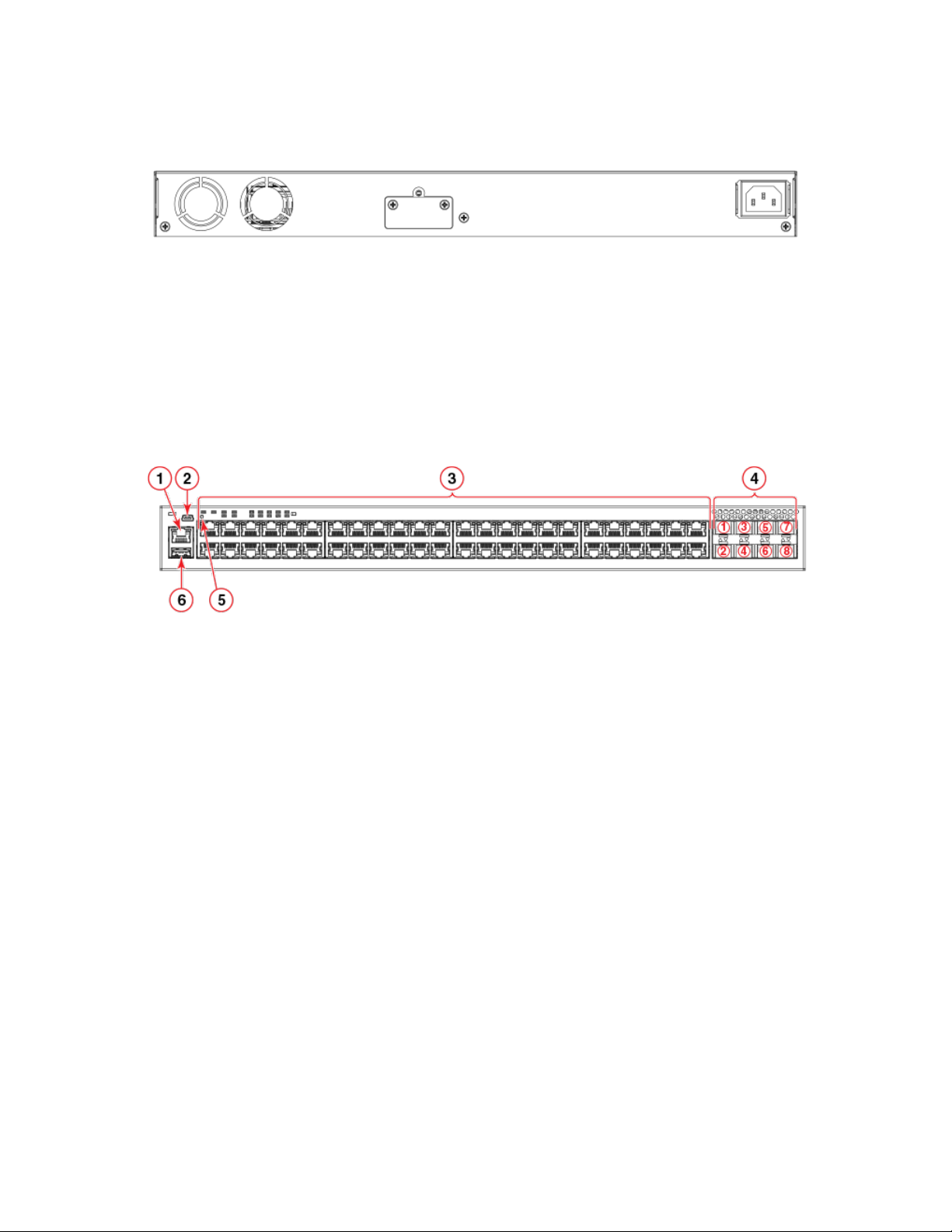
FIGURE 3 ICX 7250-24G rear panel
Brocade ICX 7250 Switch Hardware Installation Guide
Part Number: 53-1003898-05 13
Page 14
Hardware features
FIGURE 4 ICX 7250-48 rear panel
Network and management interfaces
Each device includes the following management interfaces.
• Console management interface (mini-USB port)
• Out-of-band management interface (RJ-45 port)
The ports are located on the front panels of the devices. The following gure shows an example of a 48-port device.
FIGURE 5 Network and management interfaces on a 48-port model
1. Out-of-band management port (RJ-45)
2. Console port (mini-USB)
3. Slot 1 (10/100/1000 Mbps ports - RJ-45)
4. Slot 2 (SFP+ uplink or stacking ports)
5. Reset button - not a management interface, shown for reference only.
The reset button allows you to restart the system without switching the power supply o and on or using the CLI. When the
reset button is pressed, the system resets and the software is reloaded.
6. USB port
NOTE
24-port devices have similar front panels. For the ICX 7250-24G, the slot 2 ports are SFP ports.
Console management interface
The console management interface is a mini-USB port that allows you to
emulation application from a directly connected PC or through a terminal server.
congure and manage the device using a third-party terminal
Out-of-band management interface
The out-of-band management interface is an RJ-45 port that allows you to access,
congure and manage the device from the network.
14 Part Number: 53-1003898-05
Brocade ICX 7250 Switch Hardware Installation Guide
Page 15

Hardware features
Network interfaces for devices
The Brocade ICX 7250 contains the following network interfaces:
• 10/100/1000 Mbps ports with RJ-45 copper connectors
• SFP or SFP+ ports
SFP ports support 1 Gbps port speed. SFP+ ports support both 1 Gbps and 10 Gbps port speeds.
NOTE
Refer to the Brocade ICX 7250 Switch Technical Specications on page 91 to see the ports supported by your
model.
Slot designations
Refer to Network and management interfaces on page 14 for the location of slot 1 and slot 2 on the front panel of the 24-port models
and the 48-port models.
TABLE 2 Slot designations for ICX 7250 devices
Device Slot 1 (10/100/1000 BASE-T ports) Slot 2 (SFP and SFP+ ports)
Brocade ICX 7250-24G RJ-45 ports 1-24 SFP ports 1-4
Brocade ICX 7250-24 RJ-45 ports 1-24 SFP+ ports 1-8
Brocade ICX 7250-24P RJ-45, PoE/PoE+ ports 1-24 SFP+ ports 1-8
Brocade ICX 7250-48 RJ-45 ports 1-48 SFP+ ports 1-8
Brocade ICX 7250-48P RJ-45, PoE/PoE+ ports 1-48 SFP+ ports 1-8
10/100/1000 BASE-T ports
All devices provide 24 or 48 RJ-45 ports that operate at 10 Mbps or 100 Mbps half or full duplex, or at 1000 Mbps full duplex.
Because all ports support automatic MDI or MDI-X operation, you can use straight-through cables for all network connections to PCs,
servers, or other devices or hubs. In addition, it is ideal (and preferred) to use straight-through cables for switch-to-switch connections.
Each port supports auto-negotiation, so the optimum transmission mode (half or full duplex), and the data rate (10, 100, or 1000 Mbps)
can be selected automatically. If a device connected to one of these ports does not support auto-negotiation, the communication mode
of the port can be congured manually.
SFP or SFP+ ber ports
The Brocade ICX 7250-24G contains four small form-factor pluggable (SFP) ports (ports 1 through 4). The top row contains oddnumbered ports and the bottom row contains even-numbered ports. These ports reside on slot 2 of the switch and can be used as
uplink (data) ports. These ports support 1 Gbps but not 10 Gbps port speeds.
All other Brocade ICX 7250 devices contain eight SFP+ ports that support 1 Gbps or 10 Gbps port speeds. The top row ports are odd
numbered (ports 1, 3, 5, and 7) and the bottom row ports are even numbered (ports 2, 4, 6, and 8). All ports can be used for stacking or
uplinking.
NOTE
You may need software licenses to enable some SFP+ ports at the full 10 Gbps. Refer to the FastIron Ethernet Switch
Software Licensing Guide for more information.
For information about supported SFP and SFP+ transceivers, refer to the Brocade datasheet.
Brocade ICX 7250 Switch Hardware Installation Guide
Part Number: 53-1003898-05 15
Page 16

Hardware features
Specifying a port address
You can specify a port address for an uplink (data) port, a stacking port, or a management port.
Specifying a data port
The port address format is stack-unit/slot/port:
• stack-unit: Species the stack unit ID. The range is from 1 through the maximum number of devices supported in a stack. Refer
to the technical specications for your device for the actual value. If the device is not part of a stack, the stack unit ID is 1.
• slot: Species the slot number; either 1 or 2.
• port: Species the port number in the slot. The range is from 1 through 24 (24-port models) or 1 through 48 (48-port models)
for the RJ-45 ports. For the SFP ports, the range is from 1 through 4, and for the SFP+ ports, the range is from 1 through 8.
The following example shows how to specify port 2 in slot 1 of a device that is not part of a stack:
device (config)# interface ethernet 1/1/2
Specifying a stacking port
The port address format is stack-unit/slot/port:
• stack-unit:
devices (units) that can be supported in the stack.
• slot: Species the slot number. Stacking ports are in slot 2.
• port: Species the port number in the slot.
Species the stack unit ID. For models that support stacking, the range is from 1 through the maximum number of
The following example shows how to specify stacking port 3 in slot 2 of unit 3 in a stack:
device (config)# interface ethernet 3/2/3
Specifying a management port
The management port number is always 1. This example shows how to specify the management port:
device (config)# interface management 1
Port, system, and power status LEDs
The devices include LEDs that indicate the status of device components.
NOTE
The following gures show examples of the port status LEDs for similar ports are present for models with a higher number of
ports.
16 Part Number: 53-1003898-05
Brocade ICX 7250 Switch Hardware Installation Guide
Page 17
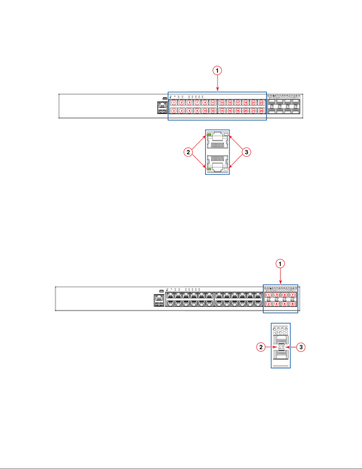
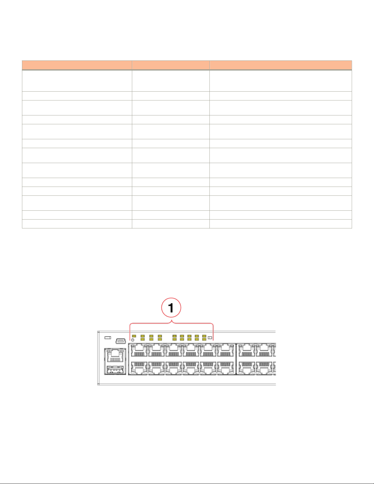
FIGURE 6 Port status LEDs on RJ-45 ports
1. RJ-45 ports
Hardware features
2. Status LEDs for corresponding ports
3. PoE/PoE+ LEDs for corresponding ports
NOTE
The PoE/PoE+ LEDs are reserved on models that do not support PoE or PoE+ operation.
FIGURE 7 Port status LEDs for SFP or SFP+ ports
1. SFP or SFP+ ports
2. Bi-color status LED for upper port
3. Bi-color status LED for lower port
Brocade ICX 7250 Switch Hardware Installation Guide
Part Number: 53-1003898-05 17
Page 18
Hardware features
TABLE 3 Port status LEDs
LED Condition Status
RJ-45 (1-24/48) On/Flashing Green The port has established a valid link at 10, 100, or 1000
Mbps. Flashing indicates the port is transmitting and receiving
user packets.
O A link is not established with a remote port.
PoE/PoE+ (1-24/48) On/Green The port is providing PoE or PoE+ power to a connected
device.
O The port is not providing PoE or PoE+ power.
SFP (F1 - F4) for ICX 7250-24G devices On/Flashing Green The SFP port is operating at 1 Gbps. Flashing indicates the
port is transmitting and receiving user packets at 1 Gbps.
O A link is not established with a remote port.
SFP+ (X1 - X8) for all other ICX 7250 devices On/Flashing Green The SFP+ port is operating at 10 Gbps. Flashing indicates the
port is transmitting and receiving user packets at 10 Gbps.
On/Flashing Yellow The SFP+ port is operating at 1 Gbps. Flashing indicates the
port is transmitting and receiving user packets at 1 Gbps.
O A link is not established with a remote port.
Out-of-band management port (RJ-45) Green The management port link is up at 1000Base-T.
O Either the management port link is up at 100Base-Tx/10Base-
T, or the link is down.
Blinking green The port is receiving and transmitting data.
O No data is being received or transmitted.
The following gure shows an example of the system status LEDs.
NOTE
Not all models have all the LEDs and the location of the LEDs on the front panel may also be slightly
dierent.
FIGURE 8 System status LEDs on the ICX 7250-48P
1. System status LEDs
The following gure shows the system status LEDs for ICX 7250 models.
18 Part Number: 53-1003898-05
Brocade ICX 7250 Switch Hardware Installation Guide
Page 19
Hardware features
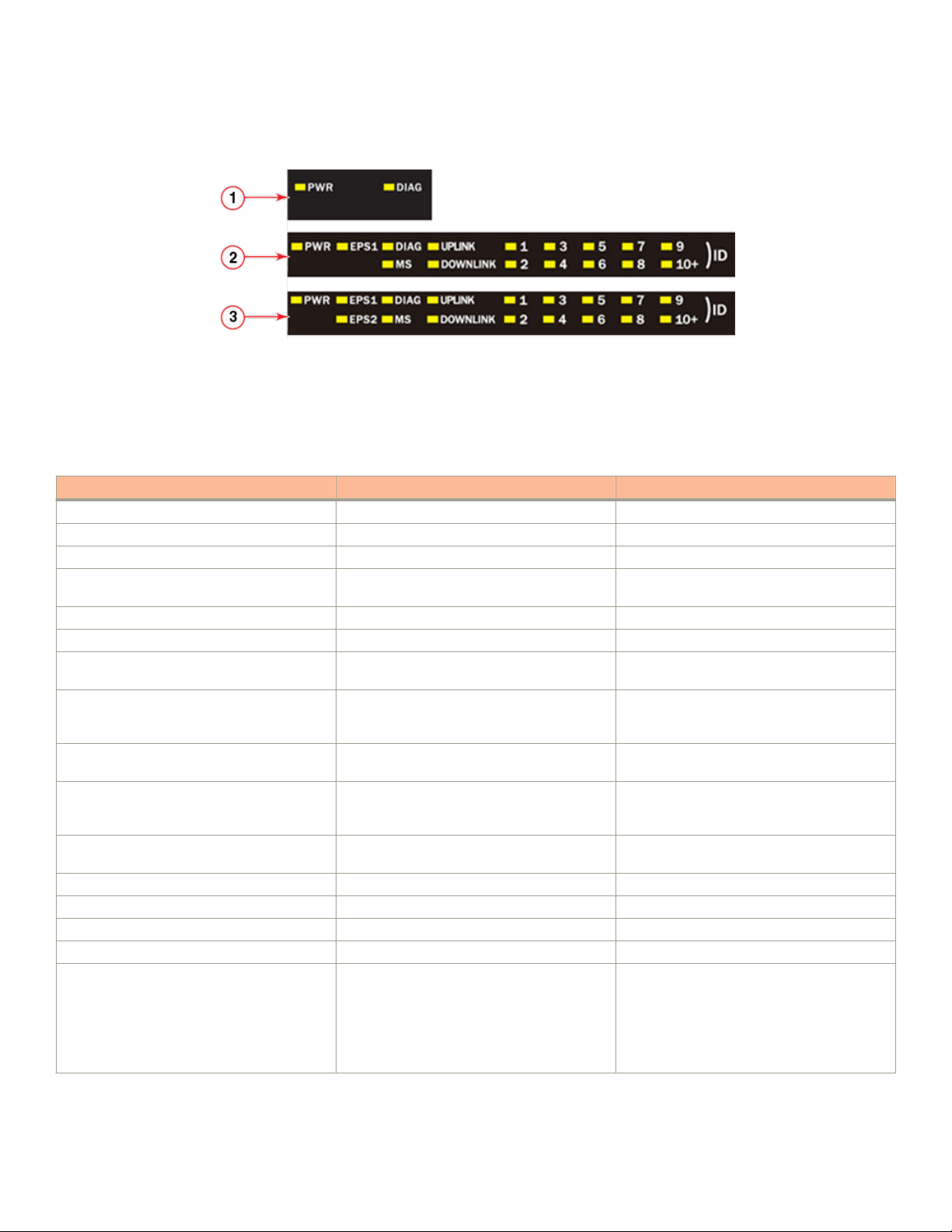
FIGURE 9 System status LEDs for ICX 7250 models
1. ICX 7250-24G LEDs
2. ICX 7250-24, ICX 7250-24P, ICX 7250-48 LEDs
3. ICX 7250-48P LEDs
TABLE 4 System status LEDs
LED Condition Status
PWR Green Power supply is operating normally.
Yellow Power supply fault.
O Power supply o.
EPS1 and EPS2 (for supported models) Green EPS1 and EPS2 power supplies are operating
normally.
Yellow EPS1 and EPS2 power supply fault.
O EPS1 and EPS2 o or not present.
DIAG Flashing Green System self-diagnostic test in progress. System
reloads automatically.
Steady Yellow System self-diagnostic test has detected a fault.
(Fan, thermal, or any interface fault.) The user
must reload the system.
MS Green The device is the Active controller. Flashing
indicates the system is initializing.
Yellow Indicates the device is the Standby controller.
Flashing indicates the system is in Master
arbitration or selection state.
O Device is operating as a stack member, or is in
standalone mode.
UPLINK Green Uplink port is operating normally.
O Uplink has failed or there is no link.
DOWNLINK Green Downlink port is operating normally.
O Downlink has failed or there is no link.
1-10+ (ID)
(Switch ID in the stack)
Green Indicates the switch ID in the stack.
The switch can display up to 19 switch IDs. The
10+ LED is used in conjunction with the 1
through 9 LEDs to indicate numbers greater
than 10. The number of devices supported in a
stack is 12.
Brocade ICX 7250 Switch Hardware Installation Guide
Part Number: 53-1003898-05 19
Page 20
Hardware features
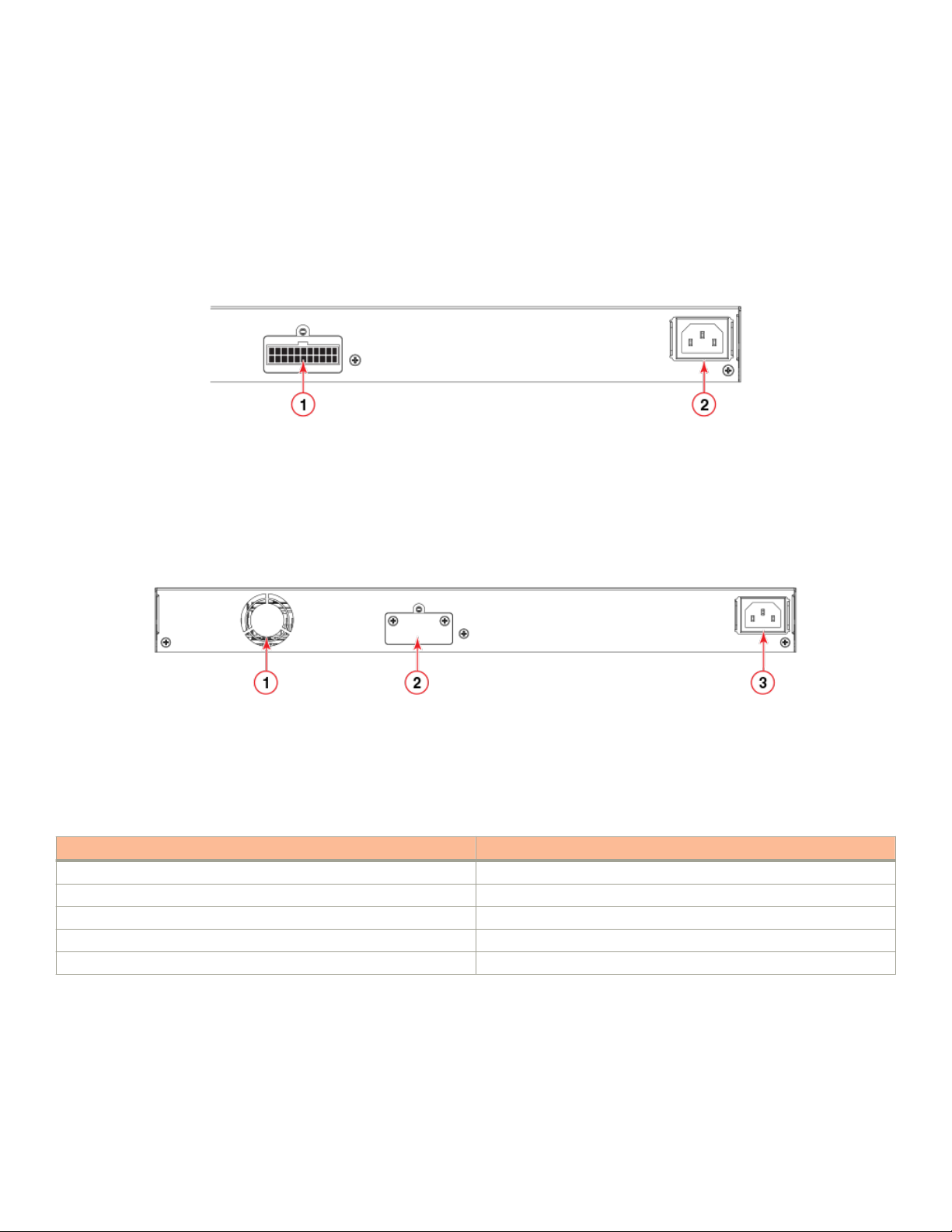
Power supplies
The devices have one standard C14 AC power supply receptacle on the rear panel of the device for an AC power cord that uses a C13
connector. In addition, there is an optional connector on some models for the power cord from an external power supply (EPS4000) that
can provide DC power to the device in the event the internal power supply fails or for supplemental power for PoE or PoE+ applications.
The following gure shows an example of a typical rear panel for an ICX 7250 device.
FIGURE 10 ICX 7250 power supply connectors
1. External power supply (EPS4000) connector
2. AC power supply socket
NOTE
The power connector for the EPS4000 is typically covered with a lid that is screwed on as shown in the following gure. To
ensure proper device cooling, keep the connector covered when not in use.
1. Fan
2. External power supply (EPS4000) connector with cover on
3. AC power supply socket
TABLE 5 EPS4000 connectors on the ICX 7250 models
Model EPS4000 connectors
Brocade ICX 7250-24G 0
Brocade ICX 7250-24 1
Brocade ICX 7250-24P 1
Brocade ICX 7250-48 1
Brocade ICX 7250-48P 1
Power supply usage
The Brocade ICX 7250 models support specic AC power supply inputs and a number of PoE and PoE+ ports with an internal power
supply.
20 Part Number: 53-1003898-05
Brocade ICX 7250 Switch Hardware Installation Guide
Page 21

NOTE
Depending on the conguration, each EPS4000 connection from the device to the EPS4000 can add 24 ports of PoE (Class
3) or 12 ports of PoE+ power (54-volt supply) in addition to the internal power supply by providing system power backup. If the
overall PoE requirement is less than the power budget of 370 W (or 740 W), the device can support 24 (or 48) PoE ports. The
system power (12-volt supply) portion of the EPS4000 can be used for internal system power redundancy.
TABLE 6 AC power supply and PoE and PoE+ usage
Model Maximum power draw from AC line
input (Watts)
Brocade ICX 7250-24G 44.4 0 0
Brocade ICX 7250-24 57.6 0 0
Brocade ICX 7250-24P 454.0 24 (class 3) 12 (class 4)
Brocade ICX 7250-48 69.5 0 0
Brocade ICX 7250-48P 942.0 48 (class 3) 24 (class 4)
Number of PoE ports supported
with internal power supply
Number of PoE+ ports supported
with internal power supply
Hardware features
Brocade ICX 7250 Switch Hardware Installation Guide
Part Number: 53-1003898-05 21
Page 22

22 Part Number: 53-1003898-05
Brocade ICX 7250 Switch Hardware Installation Guide
Page 23
Installation
• Items included with the ICX 7250 device...............................................................................................................................................23
• Conguration requirements...........................................................................................................................................................................23
• Summary of installation tasks.......................................................................................................................................................................24
• Installation precautions....................................................................................................................................................................................24
• Preparing the installation site........................................................................................................................................................................25
• Installing the device...........................................................................................................................................................................................26
• Connecting devices in a traditional stack.................................................................................................................................................56
• Powering on the system................................................................................................................................................................................. 59
DANGER
The procedures in this manual are for qualied service personnel.
DANGER
Before beginning the installation, see the precautions in “Power precautions.”
CAUTION
Disassembling any part of the power supply and fan assembly voids the warranty and regulatory certications. There are no
user-serviceable parts inside the power supply and fan assembly.
Items included with the ICX 7250 device
ICX 7250 devices ship with all of the following items included in your shipping container. Verify the contents of your shipping container.
If any items are missing, contact the place of purchase.
• ICX 7250 device
• Rack mounting kit containing two L-shaped mounting brackets and two sets of eight sink-head screws
• Wall mounting kit containing two wall-mount screws and two plastic anchors
• Two-post rack kit containing four rack-mounting screws and four cage nuts
• One AC power cord (US only)
• Power cord retainer clip
• Console cable
• DB9 adapter
• Four rubber feet
• China ROHS sheet
• Read Me First document
Conguration requirements
To manage the ICX 7250, you need a management station, such as a PC running a terminal emulation application, for serial connection
to the device.
Use the serial connection to perform basic
information is required to manage the system using the CLI through Telnet or Brocade Network Advisor.
conguration tasks, including assigning an IP address and network mask to the system. This
Brocade ICX 7250 Switch Hardware Installation Guide
Part Number: 53-1003898-05 23
Page 24
Summary of installation tasks
Summary of installation tasks
Follow the steps in the following table to install your device. Details for each of these steps are provided on the pages indicated.
TABLE 7 Installation tasks
Task number Task Where to nd more information
1 Ensure that the physical environment that will
host the device has the proper cabling and
ventilation.
2 Unpack the device and all included accessories. Items included with the ICX 7250 device on
3 Install the device on a desktop, or in an
equipment rack.
4 Once the device is installed, plug the device into
a nearby power source that adheres to the
regulatory requirements outlined in this manual.
Preparing the installation site on page 25
page 23
Installing the device on page 26
Powering on the system on page 59
Installation precautions
Follow all precautions when installing a device.
General precautions
DANGER
All ber-optic interfaces use Class 1 lasers.
CAUTION
Do not install the device in an environment where the operating ambient temperature might exceed 50°C (122°F).
CAUTION
Make sure the airow around the front, and back of the device is not
restricted.
Lifting precautions
DANGER
Make sure the rack housing the device is adequately secured to prevent it from becoming unstable or falling over.
DANGER
Mount the devices you install in a rack as low as possible. Place the heaviest device at the bottom and progressively place
lighter devices above.
Power precautions
CAUTION
Use a separate branch circuit for each power cord, which provides redundancy in case one of the circuits fails.
24 Part Number: 53-1003898-05
Brocade ICX 7250 Switch Hardware Installation Guide
Page 25

CAUTION
Ensure that the device does not overload the power circuits, wiring, and over-current protection. To determine the
possibility of overloading the supply circuits, add the ampere (amp) ratings of all devices installed on the same circuit as the
device. Compare this total with the rating limit for the circuit. The maximum ampere ratings are usually printed on the
devices near the input power connectors.
DANGER
Disconnect the power cord from all power sources to completely remove power from the device.
DANGER
If the installation requires a dierent power cord than the one supplied with the device, make sure you use a power cord
displaying the mark of the safety agency that denes the regulations for power cords in your country. The mark is your
assurance that the power cord can be used safely with the device.
Preparing the installation site
Before installing the device, plan its location and orientation relative to other devices and equipment.
Preparing the installation site
Cabling infrastructure
Ensure that the proper cabling is installed at the site. For information about supported SFP and SFP+ transceivers and cable lengths and
types, refer to the Brocade optics family datasheet.
Installation location
Devices can be mounted in a standard 19-inch equipment rack, on the wall, or on a
The site should meet the following requirements:
• Maintain the operating environment as specied in the Technical Specications.
• Allow a minimum of 7.62 cm (3 in.) of space between the front and the back of the device and walls or other obstructions for
proper airow.
• Allow at least 7.62 cm (3 in.) of space at the front and back of the device for the twisted-pair, ber-optic, and power cabling.
• The site should be accessible for installing, cabling, and maintaining the devices.
• Allow the status LEDs to be clearly visible.
• Allow for twisted-pair cables to be routed away from power lines, uorescent lighting xtures, and other sources of electrical
interference, such as radios and transmitters.
• Allow for the unit to be connected to a separate grounded power outlet that provides 100 to 240 VAC, 50 to 60 Hz, within 2 m
(6.6 ft) of each device, and is powered from an independent circuit breaker. As with any equipment, a lter or surge suppressor
is recommended.
• Some combinations of intake and exhaust airows may not be compatible with your environment.
at surface.
Brocade ICX 7250 Switch Hardware Installation Guide
Part Number: 53-1003898-05 25
Page 26

Installing the device
Rack mount installation considerations
Before mounting the device in a rack, ensure that the following rack mount installation requirements are met:
• Temperature: Because the temperature within a rack assembly may be higher than the ambient room temperature, check that
the rack-environment temperature is within the specied operating temperature range. Refer to Brocade ICX 7250 Switch
Technical Specications on page 91.
• Airow: Be sure that the airow direction for all equipment in a rack is the same or consistent.
• Mechanical loading: Do not place any equipment on top of a rack-mounted unit.
• Circuit overloading: Be sure that the supply circuit to the rack assembly is not overloaded.
• Grounding: Rack-mounted equipment should be properly grounded.
Installing the device
You can install the device on a desktop, the wall, or in an equipment rack.
DANGER
Mount the devices you install in a rack as low as possible. Place the heaviest device at the bottom and progressively place
lighter devices above.
Desktop installation
Complete the following steps to install the ICX 7250 device on a desktop or other
dierent than the one in the following illustration.
DANGER
This equipment is suitable for mounting on concrete or other noncombustible surfaces only.
at surface. The device you are installing might look
26 Part Number: 53-1003898-05
Brocade ICX 7250 Switch Hardware Installation Guide
Page 27
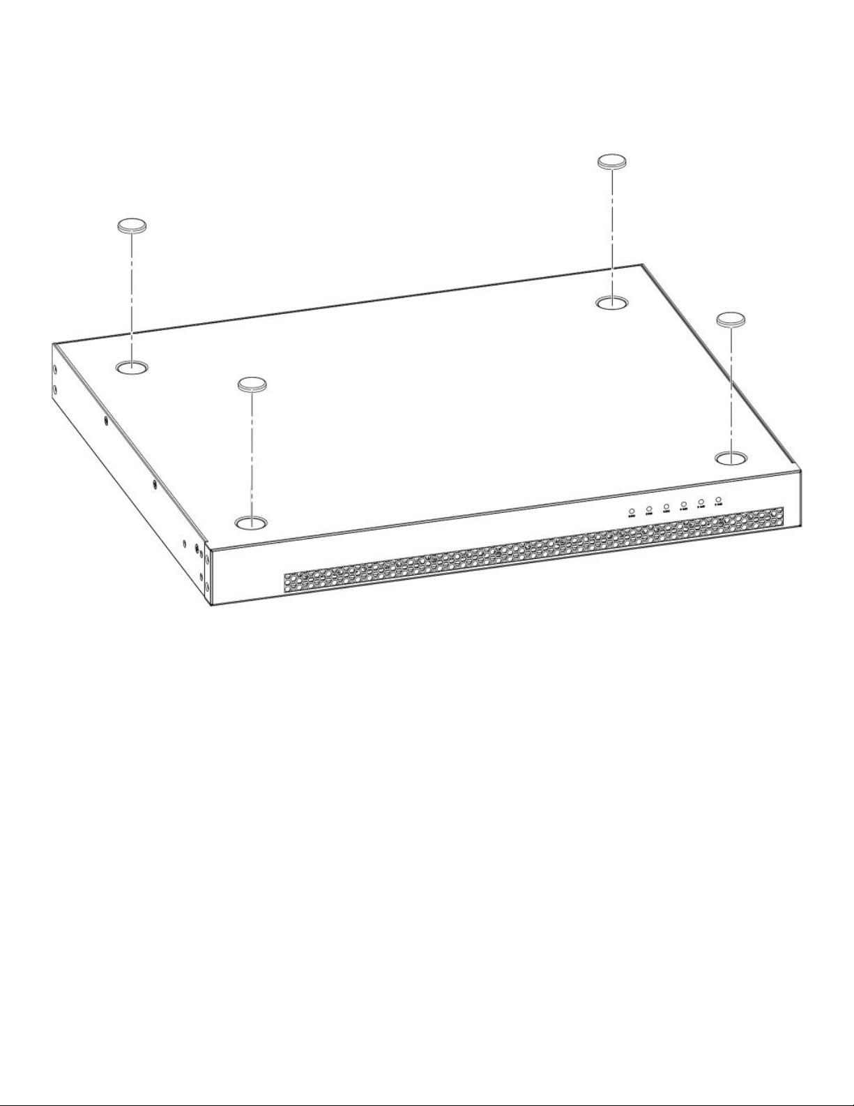
FIGURE 11 Attaching the adhesive feet
Installing the device
1. Attach the four adhesive feet to the bottom of the device. If installing multiple devices, attach the adhesive feet to each device.
2. Set the device on a at desktop, table, or shelf near an AC power source. Make sure that adequate ventilation is provided for the
system. A 7.62 cm (3 in.) clearance is recommended on each side.
3. If installing a single device only, proceed to Powering on the system on page 74. If installing multiple devices, place each
device squarely on top of the one below.
Installing the device into a rack
This section describes the procedures you use to mount the device into a rack.
The Brocade ICX 7250 can be installed in a 2-post or 4-post rack.
The device ships with a 2-post rack. To use the rack that ships with the product, refer to Installing the device using the included two-post
rack mount kit on page 28.
To install the product into a four-post rack, you can order one of two four-post rack kits with the part number XBR-R000295 or
XBR-000296. For the procedures to install these kits, refer to Installing the 1U, 1.5U, and 2U Universal Kit for Four Post Racks (XBR-
R000295) on page 29 and Installing the Universal Four-Post Rack Kit (XBR-R000296) on page 43.
Brocade ICX 7250 Switch Hardware Installation Guide
Part Number: 53-1003898-05 27
Page 28
Installing the device
Installing the device using the included two-post rack mount kit
Use this procedure to install the device to a 2-post rack using the rack-mount ears that are included with the device.
DANGER
Make sure the rack housing the device is adequately secured to prevent it from becoming unstable or falling over.
NOTE
You need a #2 Phillips screwdriver for rack mount installation.
Complete the following steps to mount devices in a rack. The example shows a front-mounting.
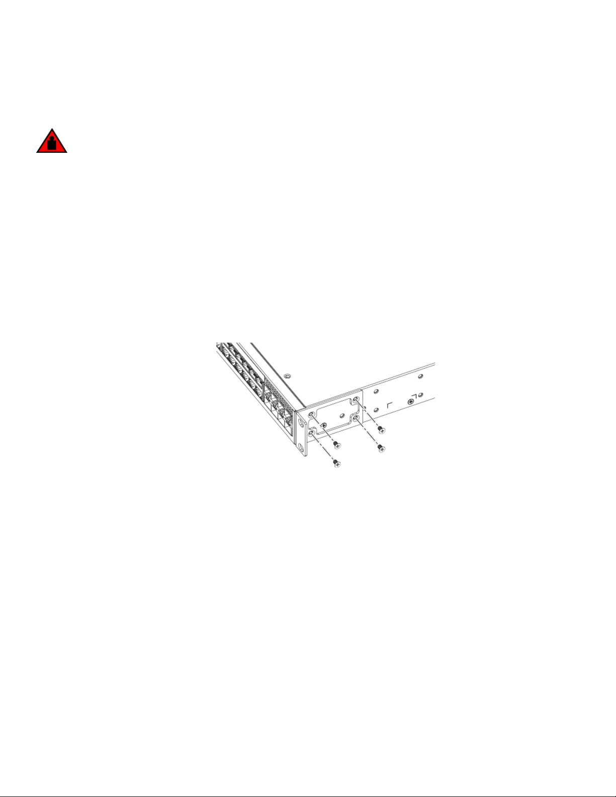
1. Remove the rack mounting kit from the shipping carton. The kit contains two L-shaped mounting brackets and two sets of eight
sink-head screws.
2. Using a Phillips screwdriver, attach the mounting brackets to the sides of the device using eight #6-32 sink-head screws, four
screws on each side.
NOTE
The #6-32 sink-head screws are for front-mounting. Use the #8-32 screws for rear-mounting.
FIGURE 12 Attaching the rack mounting brackets for the ICX 7250
3. Remove the two-post rack kit from the shipping carton. The kit contains four rack-mounting screws and four cage nuts.
4. Insert the cage nuts in the two-post rack where you want to mount the device.
28 Part Number: 53-1003898-05
Brocade ICX 7250 Switch Hardware Installation Guide
Page 29
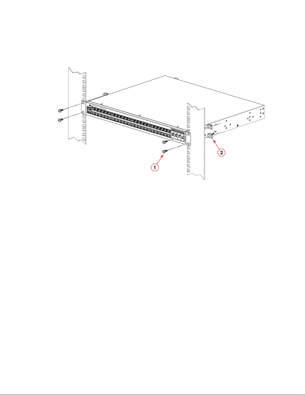
5. Using a Phillips screwdriver, mount the device in a two-post rack using four rack-mounting screws.
FIGURE 13 Installing the device in a two-post rack
Installing the device
1. Rack-mounting screws
2. Cage nuts
6. If installing a single device only, proceed to Powering on the system on page 59. If installing multiple devices, mount them in
the rack, one above the other.
Installing the 1U, 1.5U, and 2U Universal Kit for Four Post Racks (XBR-R000295)
Use the following instructions to install a 1U, 1.5U, or 2U device in a 19-in. (48.3 cm) EIA rack using the 1U, 1.5U, and 2U Universal Kit
for Four Post Racks (XBR-R000295).
The device can be installed so that the port side is either ush with the front posts or recessed with the non-port side ush with the rear
posts. A recessed position allows a more gradual bend in the ber-optic cables connected to the device and less interference in the aisle
at the front of the rack.
NOTE
Hardware devices illustrated in these procedures are only for reference and may not depict the device you are installing into the
rack.
Installation requirements
Review the installation and facility requirements for your product before mounting the device. Refer to the hardware installation guide for
your product for more information.
Use Electronic Industries Association (EIA) standard racks. Provide space in a 19-in. (48.3 cm) EIA rack, as required for the device type,
with a minimum distance of 24 in. (609.60 mm) and a maximum distance of 32 in. (812.80 mm) between the front and back posts.
Brocade ICX 7250 Switch Hardware Installation Guide
Part Number: 53-1003898-05 29
Page 30
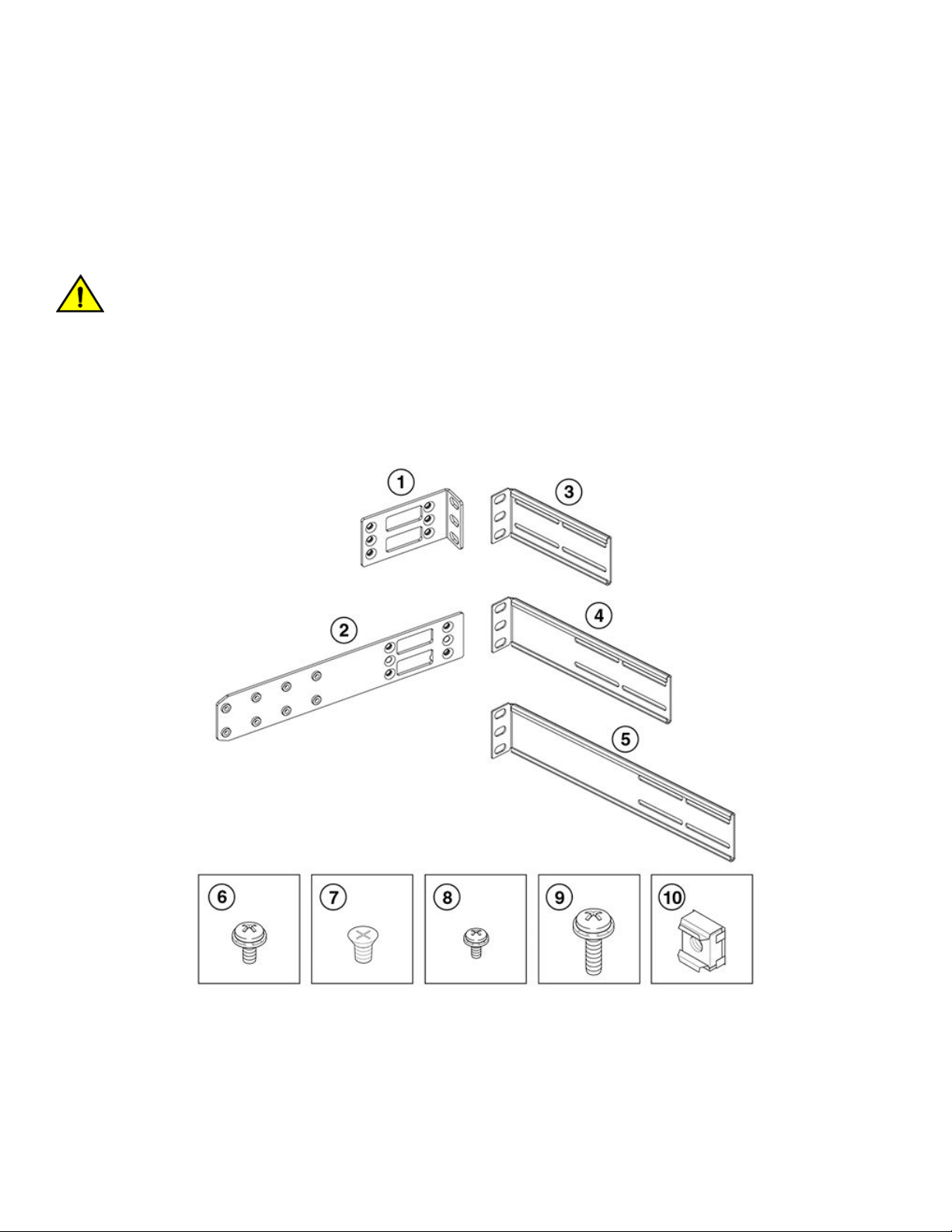
Installing the device
Time and items required
Allow 15 to 30 minutes to complete this procedure. Note the following requirements to ensure correct installation and operation.
The following items are required to install the device using the Universal Four-Post Rack Kit:
• #2 Phillips torque screwdriver
• 1/4-inch slotted-blade torque screwdriver
CAUTION
Use the screws specied in the procedure. Using longer screws can damage the
device.
Parts list
The following parts are provided with the 1U, 1.5U, and 2U Universal Kit for Four Post Racks Installation (XBR-R000295).
FIGURE 14 Rack kit parts
1. Front brackets (2)
2. Bracket extensions (2)
3. Rear brackets, short (2)
4. Rear brackets, medium (2)
5. Rear brackets, long (2)
30 Part Number: 53-1003898-05
6. Screw, 8-32 x 5/16-in., panhead Phillips (8)
7. Screw, 8-32 x 5/16-in., athead Phillips (16)
8. Screw, 6-32 x 1/4-in., panhead Phillips (8)
9. Screw, 10-32 x 5/8-in., panhead Phillips (8)
10. Retainer nut, 10-32 (8)
Brocade ICX 7250 Switch Hardware Installation Guide
Page 31

Installing the device
Ensure that the items listed and illustrated are included in the kit. Note that not all parts may be used with certain installations depending
on the device type.
CAUTION
Use the screws specied in the procedure. Using longer screws can damage the
device.
Flush-front mounting the device in the rack
CAUTION
The device must be turned o and disconnected from the fabric during this
procedure.
NOTE
The illustrations in the rack installation procedures show a 1U device, but the instructions are the same for a 1.5U or 2U device.
The illustrations in the rack installation procedures are for reference only and may not show the actual device.
Complete the following tasks to install the device in a four-post rack:
1. Attaching the front brackets on page 45
2. Attaching the extension brackets to the device on page 46
3. Installing the device in the rack on page 46
4. Attaching the rear brackets to the extensions on page 47
5. Attaching the rear brackets to the rack posts on page 48
Attaching the front brackets
Complete the following steps to attach the front brackets to the device.
1. Position the right front bracket with the at side against the right side of the device at the front of the device, as shown in Figure
15.
2. Insert four 8-32 x 5/16-in. athead screws through the vertically aligned holes in the bracket and then into the holes on the
side of the device. Use the upper and lower screw holes, leaving the center holes empty.
3. Repeat Step 1 and Step 2 to attach the left front bracket to the left side of the device.
Brocade ICX 7250 Switch Hardware Installation Guide
Part Number: 53-1003898-05 31
Page 32

Installing the device
4. Tighten all the 8-32 x 5/16-in. screws to a torque of 15 in-lb (17 cm-kg).
FIGURE 15 Attaching the front brackets
1. Device
2. Front brackets
3. Screws, 8-32 x 5/16-in., athead Phillips
Attaching the extension brackets to the device
Complete the following steps to attach the extension brackets to the device. There are medium and long extension brackets that you can
use for this step. Choose the correct extension bracket for the depth of your rack.
1. Select the proper length extension bracket for your rack depth.
2. Position the right extension bracket along the side of the device as shown in Figure 16.
3. Insert four 8-32 x 5/16-in. athead screws through the vertically aligned holes in the extension bracket and then into the holes
on the side of the device. Use the upper and lower screw holes, leaving the center holes empty.
4. Repeat Step 1 and Step 2 to attach the left extension bracket to the left side of the device.
32 Part Number: 53-1003898-05
Brocade ICX 7250 Switch Hardware Installation Guide
Page 33

5. Tighten all the 8-32 x 5/16-in. screws to a torque of 15 in-lb (17 cm-kg).
FIGURE 16 Attaching the extension brackets to the device
Installing the device
1. Bracket extensions 2. Screws, 8-32 x 5/16-in., athead Phillips
Installing the device in the rack
Complete the following steps to install the device in the rack.
1. Position the device in the rack, as shown in Figure 17, providing temporary support under the device until the rail kit is secured
to the rack.
2. Attach the right front bracket to the right front rack post using two 10-32 x 5/8-in. panhead screws and two retainer nuts. Use
the upper and lower holes in the bracket.
3. Attach the left front bracket to the left front rack post using two 10-32 x 5/8-in. panhead screws and two retainer nuts. Use the
upper and lower holes in the bracket.
Brocade ICX 7250 Switch Hardware Installation Guide
Part Number: 53-1003898-05 33
Page 34

Installing the device
4. Tighten all the 10-32 x 5/8-in. screws to a torque of 25 in-lb (29 cm-kg).
FIGURE 17 Positioning the device in the rack
1. Screws, 10-32 x 5/8-in., panhead Phillips 2. Retainer nuts, 10-32
Attaching the rear brackets to the extensions
Complete the following steps to attach the rear brackets to the extensions. There are short and long rear brackets that you can use for this
step. Choose the correct bracket for the depth of your rack.
1. Select the proper length rear bracket for your rack depth.
2. Slide the right rear bracket onto the right extension, as shown in Figure 18.
The short rear brackets are shown. Use the rst and third vertical pairs of holes for the screws.
Refer to Figure 19 for the positioning of the medium or long brackets and screws.
3. Attach the brackets using four 6-32 x 1/4-in. panhead screws.
4. Repeat Step 2 and Step 3 to attach the left rear bracket to the left extension.
34 Part Number: 53-1003898-05
Brocade ICX 7250 Switch Hardware Installation Guide
Page 35

5. Adjust the brackets to the rack depth and tighten all the 6-32 x 1/4-in. screws to a torque of 9 in-lb (10 cm-kg).
FIGURE 18 Attaching the rear brackets to the extensions
Installing the device
1. Rear brackets 2. Screws, 6-32 x 1/4-in., panhead Phillips
FIGURE 19 Attaching the medium or long rear brackets to the extensions
Brocade ICX 7250 Switch Hardware Installation Guide
Part Number: 53-1003898-05 35
Page 36

Installing the device
1. Rear bracket, medium or long
2. Screws, 6-32 x 1/4-in., panhead Phillips
Attaching the rear brackets to the rack posts
Complete the following steps to attach the rear brackets to the rack posts.
1. Attach the right rear bracket to the right rear rack post using two 10-32 x 5/8-in. panhead screws and two retainer nuts, as
shown in Figure 20. Use the upper and lower holes in the bracket.
2. Attach the left rear bracket to the left rear rack post using two 10-32 x 5/8-in. panhead screws and two retainer nuts. Use the
upper and lower holes in the bracket.
3. Tighten all the 10-32 x 5/8-in. screws to a torque of 25 in-lb (29 cm-kg).
FIGURE 20 Attaching the rear brackets to the rack posts
1. Screws, 10-32 x 5/8-in., panhead Phillips 2. Retainer nuts, 10-32
Flush-rear (recessed) mounting the device in the rack
The ush-rear (recessed) mounting is similar to the ush-front mounting except that the brackets are reversed on the device.
36 Part Number: 53-1003898-05
Brocade ICX 7250 Switch Hardware Installation Guide
Page 37

CAUTION
The device must be turned o and disconnected from the fabric during this
procedure.
NOTE
The illustrations in the rack installation procedures show a 1U device, but the instructions are the same for a 1.5U or 2U device.
The illustrations in the rack installation procedures are for reference only and may not show the actual device.
Complete the following tasks to install the device in a four-post rack:
1. Attaching the front brackets to the rear of the device on page 50
2. Attaching the extensions to the front of the device on page 50
3. Installing the device in the rack on page 51
4. Attaching the rear brackets to the extensions at the front of the device on page 52
5. Attaching the rear brackets to the front rack posts on page 54
Attaching the front brackets to the rear of the device
NOTE
In this installation, the brackets are named as listed in the parts list even though the installation of the brackets is reversed from
the ush-front installation.
Installing the device
Complete the following steps to attach the front brackets to the rear of the device.
1. Position the right front bracket with the at side against the right rear side of the device, as shown in Figure 21.
2. Insert four 8-32 x 5/16-in. athead screws through the vertically aligned holes in the bracket and then into the holes on the
side of the device. Use the upper and lower screw holes, leaving the center holes empty.
3. Repeat Step 1 and Step 2 to attach the left rear bracket to the left side of the device.
Brocade ICX 7250 Switch Hardware Installation Guide
Part Number: 53-1003898-05 37
Page 38

Installing the device
4. Tighten all the 8-32 x 5/16-in. screws to a torque of 15 in-lb (17 cm-kg).
FIGURE 21 Attaching the front brackets to the rear of the device
1. Device
2. Front brackets
3. Screws, 8-32 x 5/16-in., athead Phillips
Attaching the extensions to the front of the device
Complete the following steps to attach the extension brackets to the front of the device. There are medium and long extension brackets
that you can use for this step. Choose the correct extension for the depth of your rack.
1. Select the proper length extension bracket for your rack depth.
2. Position the right extension along the side of the device as shown in Figure 22.
3. Attach the bracket using four 8-32 x 5/16-in. athead screws.
4. Repeat Step 1 and Step 2 to attach the left front extension to the left side of the device.
38 Part Number: 53-1003898-05
Brocade ICX 7250 Switch Hardware Installation Guide
Page 39

5. Tighten all the 8-32 x 5/16-in. screws to a torque of 15 in-lb (17 cm-kg).
FIGURE 22 Attaching the bracket extensions to the device
Installing the device
1. Extension brackets 2. Screws, 8-32 x 5/16-in., athead Phillips
Installing the device in the rack
Complete the following steps to install the device in the rack.
1. Position the device in the rack, as shown in Figure 23, providing temporary support under the device until the rail kit is secured
to the rack.
2. Attach the right front bracket to the right rear rack post using two 10-32 x 5/8-in. panhead screws and two retainer nuts. Use
the upper and lower holes in the bracket.
3. Attach the left front bracket to the left rear rack post using two 10-32 x 5/8-in. panhead screws and two retainer nuts. Use the
upper and lower holes in the bracket.
Brocade ICX 7250 Switch Hardware Installation Guide
Part Number: 53-1003898-05 39
Page 40

Installing the device
4. Tighten all the 10-32 x 5/8-in. screws to a torque of 25 in-lb (29 cm-kg).
FIGURE 23 Positioning the device in the rack
1. Screws, 10-32 x 5/8-in., panhead Phillips 2. Retainer nuts, 10-32
Attaching the rear brackets to the extensions at the front of the device
Complete the following steps to attach the rear brackets to the extensions. There are short and long front brackets that you can use for
this step. Choose the correct bracket for the depth of your rack.
1. Select the proper length rear bracket for your rack depth.
2. Slide the right rear bracket onto the right extension, as shown in Figure 24.
The short rear brackets are shown. Use the rst and third vertical pairs of holes for the screws.
Refer to Figure 25 for the positioning of the medium or long brackets and screws.
3. Attach the brackets using four 6-32 x 1/4-in. screws.
4. Repeat Step 2 and Step 3 to attach the left rear bracket to the left extension.
40 Part Number: 53-1003898-05
Brocade ICX 7250 Switch Hardware Installation Guide
Page 41

5. Adjust the brackets to the rack depth and tighten all the 6-32 x 1/4-in. screws to a torque of 9 in-lb (10 cm-kg).
FIGURE 24 Attaching the rear brackets to the extensions at the front of the device
Installing the device
1. Rear brackets, short 2. Screws, 6-32 x 1/4-in., panhead Phillips
Brocade ICX 7250 Switch Hardware Installation Guide
Part Number: 53-1003898-05 41
Page 42

Installing the device
FIGURE 25 Attaching the medium or long rear brackets to the extensions
1. Rear bracket, medium or long 2. Screws, 6-32 x 1/4-in., panhead Phillips
Attaching the rear brackets to the front rack posts
Complete the following steps to attach the rear brackets to the front rack posts.
1. Attach the right rear bracket to the right front rack post using two 10-32 x 5/8-in. screws and two retainer nuts, as shown in
Figure 26. Use the upper and lower holes in the bracket.
2. Attach the left rear bracket to the left front rack post using two 10-32 x 5/8-in. screws and two retainer nuts. Use the upper and
lower holes in the bracket.
42 Part Number: 53-1003898-05
Brocade ICX 7250 Switch Hardware Installation Guide
Page 43

3. Tighten all the 10-32 x 5/8-in. screws to a torque of 25 in-lb (29 cm-kg).
FIGURE 26 Attaching the rear brackets to the front rack posts
Installing the device
1. Screws, 10-32 x 5/8-in., panhead Phillips 2. Retainer nuts, 10-32
Installing the Universal Four-Post Rack Kit (XBR-R000296)
Use the following instructions to install a device in EIA racks that are between L-12.7 to 81.28 cm deep (L-5.0 to 32.0 in.), where L is
the chassis depth, using the Universal Four-Post Rack Kit (XBR-R000296).
There are two ways you can mount the device in a four-post rack:
• With the port side ush with the front posts
• With the nonport side ush with the rear posts in a recessed position
A recessed position allows a more gradual bend in the ber-optic cables connected to the switch and less interference in the aisle at the
front of the rack.
NOTE
Although this document describes how to install both single height (1U) and double height (2U) switches, the illustrations show
a 1U switch as a typical installation.
Brocade ICX 7250 Switch Hardware Installation Guide
Part Number: 53-1003898-05 43
Page 44

Installing the device
NOTE
Hardware devices illustrated in these procedures are only for reference and may not depict the device you are installing into the
rack.
Installation requirements
Provide space in an EIA rack with the following minimum and maximum distances between the front and back posts.
NOTE
For 1U and 2U devices, two people are required to install the device in a rack. One person holds the device, while the other
screws in the front and rear "L" brackets.
TABLE 8 Space requirements
Chassis with port-side
side vents
No Applicable to port-side and nonport-side ush
Yes Applicable to port-side ush mounts. L L-12.7 cm (L-5 in.) 81.28 cm (32 in.)
Yes Applicable to nonport-side ush mounts. L L 81.28 cm (32 in.)
Notes Chassis depth Minimum rack depth Maximum rack depth
L L-12.7 cm (L-5 in.) 81.28 cm (32 in.)
mounts.
Note that if chassis depth (L) is less than 40.64 cm (16 in.), the chassis will not t into a rack with a maximum depth of 81.28 cm (32 in.)
using the universal four-post rack kit. The maximum rack depth for a chassis less than 40.64 cm (16 in.) is 81.28 cm (32 in.) minus the
dierence between the chassis depth and 40.64 cm (16 in.). For example, a chassis with a depth (L) of 35.56 cm (14 in.) is 5.08 cm (2
in.) smaller than 40.64 cm (16 in.), so it will install into a rack with a maximum depth of 81.28 cm (32 in.) - 5.08 cm (2 in.) = 76.2 cm
(30 in.).
Review the installation and facility requirements for your product before mounting the device . Refer to the Hardware Installation Guide
for your product for more information.
Time and items required
Allow 15 to 30 minutes to complete the installation.
The following items are required to install the device using the Universal Four-Post Rack Kit:
• #2 Phillips torque screwdriver
• 1/4-inch slotted-blade torque screwdriver
CAUTION
Use the screws specied in the procedure. Using longer screws can damage the
device.
Flush-front mounting
CAUTION
The device must be turned o and disconnected from the fabric during this
procedure.
NOTE
The illustrations in the rack installation procedures show a 1U device, but the instructions are the same for a 2U device. The
illustrations in the rack installation procedures are for reference only and may not show the actual device.
44 Part Number: 53-1003898-05
Brocade ICX 7250 Switch Hardware Installation Guide
Page 45

Installing the device
Complete the following tasks to install the device in a four-post rack:
1. Attaching the front brackets on page 45
2. Attaching the extension brackets to the device on page 46
3. Installing the device in the rack on page 46
4. Attaching the rear brackets to the extensions on page 47
5. Attaching the rear brackets to the rack posts on page 48
Attaching the front brackets
Complete the following steps to attach the front brackets to the device.
1. Position the right front bracket with the at side against the right side of the device at the front of the device, as shown in Figure
27.
2. Insert four 8-32 x 5/16-in. athead screws through the vertically aligned holes in the bracket and then into the holes on the
side of the device. Use the upper and lower screw holes, leaving the center holes empty.
3. Repeat step 1 and step 2 to attach the left front bracket to the left side of the device.
4. Tighten all the 8-32 x 5/16-in. screws to a torque of 15 in-lb (17 cm-kg).
FIGURE 27 Attaching the front brackets
1. The Brocade device
2. Front brackets
3. Screws, 8-32 x 5/16-in., athead Phillips
Brocade ICX 7250 Switch Hardware Installation Guide
Part Number: 53-1003898-05 45
Page 46

Installing the device
Attaching the extension brackets to the device
Complete the following steps to attach the extension brackets to the device. There are medium and long extension brackets that you can
use for this step. Choose the correct extension bracket for the depth of your rack.
1. Select the proper length extension bracket for your rack depth.
2. Position the right extension bracket along the side of the device as shown in Figure 28.
3. Insert four 8-32 x 5/16-in. athead screws through the vertically aligned holes in the extension bracket and then into the holes
on the side of the device. Use the upper and lower screw holes, leaving the center holes empty.
4. Repeat step 1 and step 2 to attach the left extension bracket to the left side of the device.
5. Tighten all the 8-32 x 5/16-in. screws to a torque of 15 in-lb (17 cm-kg).
FIGURE 28 Attaching the extension brackets to the device
1. Extension brackets 2. Screws, 8-32 x 5/16-in., athead Phillips
Installing the device in the rack
Complete the following steps to install the device in the rack.
1. Position the device in the rack, as shown in Figure 29, providing temporary support under the device until the rail kit is secured
to the rack.
2. Attach the right front bracket to the right front rack post using two 10-32 x 5/8-in. panhead screws and two retainer nuts. Use
the upper and lower holes in the bracket.
3. Attach the left front bracket to the left front rack post using two 10-32 x 5/8-in. panhead screws and two retainer nuts. Use the
upper and lower holes in the bracket.
46 Part Number: 53-1003898-05
Brocade ICX 7250 Switch Hardware Installation Guide
Page 47

4. Tighten all the 10-32 x 5/8-in. screws to a torque of 25 in-lb (29 cm-kg).
FIGURE 29 Positioning the device in the rack
Installing the device
1. Screws, 10-32 x 5/8-in., panhead Phillips 2. Retainer nuts, 10-32
Attaching the rear brackets to the extensions
Complete the following steps to attach the rear brackets to the extensions. There are short and long rear brackets that you can use for this
step. Choose the correct bracket for the depth of your rack.
1. Select the proper length rear bracket for your rack depth.
2. Slide the right rear bracket onto the right extension and attach to the extension by inserting four 6-32 x 1/4-in. panhead screws
through the bracket holes. If possible, leave at least one empty vertical pair of holes between the screws for better support.
3. Repeat step 2 to attach the left rear bracket to the left extension.
Brocade ICX 7250 Switch Hardware Installation Guide
Part Number: 53-1003898-05 47
Page 48

Installing the device
4. Adjust the brackets to the rack depth and tighten all the 6-32 x 1/4-in. screws to a torque of 9 in-lb (10 cm-kg).
FIGURE 30 Attaching the rear brackets to the extensions
1. Rear brackets 2. Screws, 6-32 x 1/4-in., panhead Phillips
Attaching the rear brackets to the rack posts
Complete the following steps to attach the rear brackets to the rack posts.
1. Attach the right rear bracket to the right rear rack post using two 10-32 x 5/8-in. panhead screws and two retainer nuts, as
shown in Figure 31. Use the upper and lower holes in the bracket.
2. Attach the left rear bracket to the left rear rack post using two 10-32 x 5/8-in. panhead screws and two retainer nuts. Use the
upper and lower holes in the bracket.
48 Part Number: 53-1003898-05
Brocade ICX 7250 Switch Hardware Installation Guide
Page 49

3. Tighten all the 10-32 x 5/8-in. screws to a torque of 25 in-lb (29 cm-kg).
FIGURE 31 Attaching the rear brackets to the rack posts
Installing the device
1. Screws, 10-32 x 5/8-in., panhead Phillips 2. Retainer nuts, 10-32
Flush-rear (recessed) mounting
The ush-rear (recessed) mounting is similar to the ush-front mounting except that the brackets are reversed on the device.
CAUTION
The device must be turned o and disconnected from the fabric during this
procedure.
NOTE
The illustrations in the rack installation procedures show a 1U device, but the instructions are the same for a 2U device. The
illustrations in the rack installation procedures are for reference only and may not show the actual device.
Complete the following tasks to install the device in a four-post rack:
1. Attaching the front brackets to the rear of the device on page 50
2. Attaching the extensions to the front of the device on page 50
3. Installing the device in the rack on page 51
4. Attaching the rear brackets to the extensions at the front of the device on page 52
5. Attaching the rear brackets to the front rack posts on page 54
Brocade ICX 7250 Switch Hardware Installation Guide
Part Number: 53-1003898-05 49
Page 50

Installing the device
Attaching the front brackets to the rear of the device
NOTE
In this installation, the brackets are named as listed in the parts list even though the installation of the brackets is reversed from
the ush-front installation.
Complete the following steps to attach the front brackets to the rear of the device.
1. Position the right front bracket with the at side against the right rear side of the device, as shown in Figure 32.
2. Insert four 8-32 x 5/16-in. athead screws through the vertically aligned holes in the bracket and then into the holes on the
side of the device. Use the upper and lower screw holes, leaving the center holes empty.
3. Repeat step 1 and step 2 to attach the left rear bracket to the left side of the device.
4. Tighten all the 8-32 x 5/16-in. screws to a torque of 15 in-lb (17 cm-kg).
FIGURE 32 Attaching the front brackets to the rear of the device
1. The Brocade device
2. Screws, 8-32 x 5/16-in., athead Phillips
3. Front brackets
Attaching the extensions to the front of the device
Complete the following steps to attach the extension brackets to the front of the device. There are medium and long extension brackets
that you can use for this step. Choose the correct extension for the depth of your rack.
1. Select the proper length extension bracket for your rack depth.
2. Position the right extension along the side of the device as shown in Figure 33.
3. Attach the bracket using four 8-32 x 5/16-in. athead screws.
4. Repeat step 1 and step 2 to attach the left front extension to the left side of the device.
50 Part Number: 53-1003898-05
Brocade ICX 7250 Switch Hardware Installation Guide
Page 51

5. Tighten all the 8-32 x 5/16-in. screws to a torque of 15 in-lb (17 cm-kg).
FIGURE 33 Attaching the bracket extensions to the device
Installing the device
1. Extension brackets 2. Screws, 8-32 x 5/16-in., athead Phillips
Installing the device in the rack
Complete the following steps to install the device in the rack.
1. Position the device in the rack, as shown in Figure 34, providing temporary support under the device until the rail kit is secured
to the rack.
2. Attach the right front bracket to the right rear rack post using two 10-32 x 5/8-in. panhead screws and two retainer nuts. Use
the upper and lower holes in the bracket.
3. Attach the left front bracket to the left rear rack post using two 10-32 x 5/8-in. panhead screws and two retainer nuts. Use the
upper and lower holes in the bracket.
Brocade ICX 7250 Switch Hardware Installation Guide
Part Number: 53-1003898-05 51
Page 52

Installing the device
4. Tighten all the 10-32 x 5/8-in. screws to a torque of 25 in-lb (29 cm-kg).
FIGURE 34 Positioning the device in the rack
1. Screws, 10-32 x 5/8-in., panhead Phillips 2. Retainer nuts, 10-32
Attaching the rear brackets to the extensions at the front of the device
Complete the following steps to attach the rear brackets to the extensions. There are short and long front brackets that you can use for
this step. Choose the correct bracket for the depth of your rack.
1. Select the proper length rear bracket for your rack depth.
2. Slide the right rear bracket onto the right extension, as shown in Figure 35.
The short rear brackets are shown. Use the rst and third vertical pairs of holes for the screws.
Refer to Figure 36 for the positioning of the short or long brackets and screws.
3. Attach the brackets using four 6-32 x 1/4-in. screws.
4. Repeat step 2 and step 3 to attach the left rear bracket to the left extension.
52 Part Number: 53-1003898-05
Brocade ICX 7250 Switch Hardware Installation Guide
Page 53

5. Adjust the brackets to the rack depth and tighten all the 6-32 x 1/4-in. screws to a torque of 9 in-lb (10 cm-kg).
FIGURE 35 Attaching the rear brackets to the extensions at the front of the device
Installing the device
1. Rear brackets, short 2. Screws, 6-32 x 1/4-in., panhead Phillips
FIGURE 36 Attaching the short or long rear brackets to the extensions
Brocade ICX 7250 Switch Hardware Installation Guide
Part Number: 53-1003898-05 53
Page 54

Installing the device
1. Rear bracket, short or long 2. Screws, 6-32 x 1/4-in., panhead Phillips
Attaching the rear brackets to the front rack posts
Complete the following steps to attach the rear brackets to the front rack posts.
1. Attach the right rear bracket to the right front rack post using two 10-32 x 5/8-in. screws and two retainer nuts, as shown in
Figure 37. Use the upper and lower holes in the bracket.
2. Attach the left rear bracket to the left front rack post using two 10-32 x 5/8-in. screws and two retainer nuts. Use the upper and
lower holes in the bracket.
3. Tighten all the 10-32 x 5/8-in. screws to a torque of 25 in-lb (29 cm-kg).
FIGURE 37 Attaching the rear brackets to the front rack posts
1. Screws, 10-32 x 5/8-in., panhead Phillips 2. Retainer nuts, 10-32
Wall mount installation
NOTE
You need a #2 Phillips screwdriver, a hammer, and a drill for wall mount installation.
Brocade recommends that you wall mount the device with the port side down.
Complete the following steps to mount the device to a wall.
54 Part Number: 53-1003898-05
Brocade ICX 7250 Switch Hardware Installation Guide
Page 55

Installing the device
DANGER
This equipment is suitable for mounting on concrete or other noncombustible surfaces only.
1. Attach the four adhesive feet to the bottom of the device.
2. Using a Phillips screwdriver, attach the wall mount brackets to the sides of the device using four #6-32 sink-head screws on
each side.
FIGURE 38 Attaching the wall mount brackets
3. Drill two holes on the wall where you want to mount the device.
4. Hammer two wall mount anchors into the holes on the wall.
Brocade ICX 7250 Switch Hardware Installation Guide
Part Number: 53-1003898-05 55
Page 56

Connecting devices in a traditional stack
5. Use the two wall mount screws to fasten the device to the wall mount anchors.
FIGURE 39 Wall mounting the device
1. Drilled holes
2. Wall mount anchors
3. Wall mount screws
Connecting devices in a traditional stack
ICX 7250 devices can operate as standalone devices and also as members of traditional stacks. A stack is a group of devices—Brocade
stackable units and their connected stacking links—that are connected so that the stack is managed as a single entity.
A traditional stack contains devices from only one model in a product family.
56 Part Number: 53-1003898-05
Brocade ICX 7250 Switch Hardware Installation Guide
Page 57

Connecting devices in a traditional stack
Stacking ports and trunks
There are eight SFP+ ports on the front panels of the ICX 7250 devices that support stacking, which can be used as uplink (data) ports
or as stacking ports. The following gure shows the ports in slot 2; the top row consists of ports 1, 3, 5, and 7, and the bottom row
consists of ports 2, 4, 6, and 8. The numbering for the ports in the following gure is provided in the format x/x/x and refers to StackID/
Slot/Port.
FIGURE 40 Stacking ports
Stacking conguration requirements
Before conguring the traditional stack using the CLI, physically connect the devices using stacking cables. For information about
conguring a stack, refer to the Brocade FastIron Stacking Conguration Guide.
Traditional stack size
A traditional stack can contain a maximum of twelve ICX 7250 devices.
Stacking topologies for a traditional stack
Both linear and ring topologies are supported in a traditional stack. In a linear stack topology there is a connection between each switch
that carries two-way communications across the stack. The physical connection between the devices can use one port (stacked-port) or
two ports (stacked-trunk) per trunk. The stack uses a pair of ports (n, n+1, where n is odd and ranges from 1 through 7) even if there is
only one physical connection between the devices in a stack. The physical connections must be from an odd-numbered port to an oddnumbered port or an even-numbered port to an even-numbered port.
Brocade ICX 7250 Switch Hardware Installation Guide
Part Number: 53-1003898-05 57
Page 58

Connecting devices in a traditional stack
NOTE
The examples in the following gures show a 24-port device. The 48-port devices show the same behavior for
stacking.
The following gure shows a linear stacking topology example.
• For the rst device in the stack, ports (1/2/1, 1/2/2) are being used as stacked ports.
• For the second device in the stack, ports (2/2/1, 2/2/2 and 2/2/3, 2/2/4) are being used as stacked ports.
• There is a single physical connection between device 1 and device 2 in the stack, ports 1/2/1 and 2/2/1 (odd-numbered port
to odd-numbered port). This is a stacked-port conguration.
• There are two physical connections between device 2 and device 3 in the stack. Port 2/2/3 is connected to port 3/2/7 (oddnumbered port to odd-numbered port) and port 2/2/4 is connected to 3/2/8 (even-numbered port to even-numbered port).
This is a stacked-trunk conguration.
FIGURE 41 Linear stacking topology
1. First device in stack
2. Second device in stack
3. Third device in stack
In a ring stacking topology, there is an extra connection between the logical rst and last devices, forming a "ring" or "closed-loop." The
closed-loop connection provides a redundant path for the stack link, so if one link fails, stack communications can be maintained.
58 Part Number: 53-1003898-05
Brocade ICX 7250 Switch Hardware Installation Guide
Page 59

FIGURE 42 Ring stacking topology
1. First device in stack
2. Second device in stack
3. Third device in stack
Powering on the system
Powering on the system
After you complete the physical installation, you can power on the system.
NOTE
The power outlet should be installed near the equipment and should be easily accessible.
1. Remove the power cord from the shipping container.
2. Install the power cord clip.
3. Attach the AC power cord to the AC connector on the rear panel.
4. Insert the power cord plug into a 100V-240V outlet.
NOTE
To turn the system o, simply unplug the power cord or
cords.
Brocade ICX 7250 Switch Hardware Installation Guide
Part Number: 53-1003898-05 59
Page 60

60 Part Number: 53-1003898-05
Brocade ICX 7250 Switch Hardware Installation Guide
Page 61

Installing the EPS4000
• EPS4000 external power supply............................................................................................................................................................... 61
• Items included with the EPS4000.............................................................................................................................................................65
• Conguration requirements...........................................................................................................................................................................65
• Summary of installation tasks.......................................................................................................................................................................65
• Installation precautions....................................................................................................................................................................................66
• Preparing the installation site........................................................................................................................................................................67
• Installing the device...........................................................................................................................................................................................67
• Installing an RPS17 PSU...............................................................................................................................................................................70
• Uninstalling an RPS17 PSU.........................................................................................................................................................................71
• Connecting the EPS4000 cord...................................................................................................................................................................72
• Powering on the system................................................................................................................................................................................. 74
• Verifying proper operation............................................................................................................................................................................. 75
• EPS4000 external power supply technical specications...............................................................................................................75
DANGER
The procedures in this manual are for qualied service personnel.
DANGER
Before beginning the installation, see the precautions in “Power precautions.”
DANGER
Be careful not to accidently insert your ngers into the fan tray while removing it from the chassis. The fan may still be
spinning at a high speed.
EPS4000 external power supply
In the event of an AC power loss or internal power supply device failure, the Brocade EPS4000 external power supply can be used as a
12 V, backup power source to a device when any of the DC power supply ports are connected to an ICX 7250 device. The EPS4000
requires a minimum of one RPS17 Power Supply Unit (PSU) to be functional. Proprietary DC cables are used to connect any of the EPS
DC ports of the EPS4000 to the rear EPS4000 port of an ICX 7250 device that is supported by the EPS4000. Each RPS17 PSU can
provide backup power to one ICX 7250 device. Even though a fully populated EPS4000 can monitor up to sixteen connected devices,
the EPS4000 can provide backup power without performance degradation to only four ICX 7250 devices.
NOTE
The primary source of 12 V power for an ICX 7250 device is the internal power supply. The EPS4000 is designed to serve
primarily as a backup source of 12 V power. You should service a failed ICX 7250 device as soon as possible after a 12 V
power failure is detected.
In case of a 54 V supply failure, the EPS4000 can provide power to multiple devices up to its capacity limit. You can set the system
priority for the power budget allocation for this scenario. The default is for the lower-numbered port to have the higher priority. Should a
higher priority device have a 54 V supply failure while a lower priority device is already being serviced by the PSU, the power supply will
not switch to provide power to the higher priority device to maintain continuity of service. The EPS4000 uses the next PoE-powerbudget cycle to reallocate power among the connected ICX 7250 devices.
Brocade ICX 7250 Switch Hardware Installation Guide
Part Number: 53-1003898-05 61
Page 62

EPS4000 external power supply
In the PoE power extension mode, the EPS4000 can also provide additional power to support the PoE ports as needed. For more
information about connecting an ICX 7250 device to the EPS4000, refer to Connecting devices to the external power supply on page
75.
Each RPS17 PSU can provide up to 740 W at 54 V and 120 W at 12 V. The RPS17 draws power from a standard AC source and
converts it to DC for use by the switches.
NOTE
The internal power supply of the ICX 7250 devices is not a eld-replaceable unit (FRU). The devices must be shut down by
administrators for replacement.
Brocade recommends that you pay attention to the PoE or PoE+ port conguration of the device when connecting to an EPS4000. The
internal power supply of each PoE or PoE+ device has a maximum number of supported PoE or PoE+ ports. Brocade recommends that
when the EPS4000 is used as a redundant power source for the PoE device, that the maximum number of PoE or PoE+ ports of the
external power supply must not exceed the maximum number of PoE or PoE+ ports of the internal power supply capability of each
device.
The following devices are supported by the Brocade EPS4000:
• ICX 7250-24
• ICX 7250-24P
• ICX 7250-48
• ICX 7250-48P
NOTE
The ICX 7250-24G is not supported by the EPS4000.
EPS4000 features and benets
• Hosts up to four hot-swappable RPS17 power supply units (PSUs).
• Provides N:1 power redundancy at 12 V with each PSU.
• Each RPS17 can deliver a maximum of 740 W at 54 V and 120 W at 12 V.
• A fully populated EPS4000 has 8 DC power ports that can monitor up to 16 switches simultaneously and provide 12 V
redundant power to four switches.
• Provides power redundancy at 54 V and true extended PoE power support.
• 1:1 and 1:2 cables support 54 V or 12 V distribution up to 1 meter.
• Universal (100-240 V) AC line cord draws power from standard power outlet.
• The EPS4000 rmware is eld-upgradeable.
• The power to the switches is maintained while the microcontroller unit (MCU) is being reset.
• The power distribution to the connected switches can be controlled per a priority scheme that you set.
EPS4000 front and rear panels
There are 32 LEDs on the front panel of the EPS4000 to indicate the status for the DC power on the 8 ports. 16 LEDs (Ex.y) are for the
54 VDC and the other sixteen (Rx.y) are for the 12 VDC supply. There is a reset button next to the LEDs. There are port LEDs for each of
the management ports. Both the serial port and the out-of-band Ethernet management ports use RJ-45 connectors. The slots for the
RPS17 PSUs are covered with slot covers. The slot cover must be removed to install the PSU.
62 Part Number: 53-1003898-05
Brocade ICX 7250 Switch Hardware Installation Guide
Page 63

FIGURE 43 EPS4000 front panel
1. Management console serial port (RJ-45)
2. RPS17 PSU slots (three populated, one with cover on)
3. AC power cord input (C14)
4. PSU release latch
EPS4000 external power supply
5. Power cord clip
6. Integrated RPS17 PSU fan
7. PSU slot cover screws
8. Reset button (sets EPS4000 conguration to factory default)
9. System status indicators
10. Out-of-band, Ethernet management port (RJ-45)
FIGURE 44 EPS4000 rear panel
1. DC power cable connector 1
2. DC power cable connector 2
3. DC power cable connector 3
4. DC power cable connector 4
5. DC power cable connector 5
6. DC power cable connector 6
7. DC power cable connector 7
8. DC power cable connector 8
Brocade ICX 7250 Switch Hardware Installation Guide
Part Number: 53-1003898-05 63
Page 64

EPS4000 external power supply
LEDs
The following gure shows the LEDs on the EPS4000.
FIGURE 45 EPS4000 LEDs
1. Ex.y: Power status indicator (54 V): x= EPS4000 connector (1-8), y = Channel or port (1-2)
2. CONFIG: EPS conguration mode indicator
3. Rx.y: Power status indicator (12 V): x = EPS4000 connector (1-8), y = Channel or port (1-2)
The following table describes the functions of the EPS4000 LEDs.
TABLE 9 System Status LEDs on the EPS4000
LED State Description
E1.1 ~ E8.1 (54 V1)
E1.2 ~ E8.2 (54 V2)
R1.1 ~ R8.1 (12 V1)
R1.2 ~ R8.2 (12 V2)
CONFIG Green Auto-conguration mode.
Management port LED Green Management port link up at 100BASE-T mode.
O No connection.
Green EPS4000 is delivering up to 370 W PoE power to switch.
Amber Switch is connected to this channel but EPS4000 does not have sucient PoE power
for this channel.
Blinking amber This channel has a fault (for example, over current).
Blinking amber and green This channel has been granted PoE power but there is a fault on the channel (for
example, over current).
O No connection.
Green Switch is connected to this channel and EPS is ready to provide 12 V backup power for
this channel.
Blinking green Switch is connected to this channel and EPS is providing 12 V backup power to this
channel.
Amber Switch is connected to this channel but EPS does not have sucient 12 V backup
power for this channel.
Blinking amber This channel had a fault (for example, over current).
Amber Manual conguration mode.
64 Part Number: 53-1003898-05
Brocade ICX 7250 Switch Hardware Installation Guide
Page 65

Summary of installation tasks
TABLE 9 System Status LEDs on the EPS4000 (continued)
LED State Description
(Left down)
Management port LED
(Right down)
O Management port link up at 10BASE-T mode or link is down.
Blinking green Indicates management port receive and transmit activity.
O Indicates no Ethernet trac on management port.
Items included with the EPS4000
The EPS4000 ships with all of the following items included in your shipping container. Verify the contents of your shipping container. If
any items are missing, contact the place of purchase.
• EPS4000 external power supply
• Rack mounting kit containing two L-shaped mounting brackets and eight sink-head screws
• Two-post rack kit containing four rack-mounting screws and four cage nuts
• Four rubber feet
• Console cable
• RJ-45 to DB9 adapter
• China ROHS sheet
• Read Me First document
Conguration requirements
conguration requirements for the EPS4000 are the same as the for the ICX 7250. Refer to Conguration requirements on page
The
23.
Summary of installation tasks
Follow the steps in the following table to install your device. Details for each of these steps are provided on the pages indicated.
TABLE 10 Installation tasks
Task number Task Where to nd more information
1 Ensure that the physical environment that will
host the device has the proper cabling and
ventilation.
2 Unpack the device and all included accessories. Items included with the EPS4000 on page 65
3 Install the device on a desktop, or in an
equipment rack.
4 Once the device is installed, plug the device into
a nearby power source that adheres to the
regulatory requirements outlined in this manual.
5 Verify that the device is working properly by
plugging it into a power source and verifying that
it passes the self test.
Preparing the installation site on page 67
section
section
Installing the device on page 67 section
Powering on the system on page 74 section
Verifying proper operation on page 75 section
Brocade ICX 7250 Switch Hardware Installation Guide
Part Number: 53-1003898-05 65
Page 66

Installation precautions
Installation precautions
Follow all precautions when installing a device.
General precautions
DANGER
All ber-optic interfaces use Class 1 lasers.
CAUTION
Do not install the device in an environment where the operating ambient temperature might exceed 50°C (122°F).
CAUTION
Make sure the airow around the front, and back of the device is not
restricted.
Lifting precautions
DANGER
Make sure the rack housing the device is adequately secured to prevent it from becoming unstable or falling over.
DANGER
Mount the devices you install in a rack as low as possible. Place the heaviest device at the bottom and progressively place
lighter devices above.
Power precautions
CAUTION
Use a separate branch circuit for each power cord, which provides redundancy in case one of the circuits fails.
CAUTION
Ensure that the device does not overload the power circuits, wiring, and over-current protection. To determine the
possibility of overloading the supply circuits, add the ampere (amp) ratings of all devices installed on the same circuit as the
device. Compare this total with the rating limit for the circuit. The maximum ampere ratings are usually printed on the
devices near the input power connectors.
DANGER
Disconnect the power cord from all power sources to completely remove power from the device.
CAUTION
Before plugging a cable into any port, be sure to discharge the voltage stored on the cable by touching the electrical
contacts to ground surface.
DANGER
If the installation requires a dierent power cord than the one supplied with the device, make sure you use a power cord
displaying the mark of the safety agency that denes the regulations for power cords in your country. The mark is your
assurance that the power cord can be used safely with the device.
66 Part Number: 53-1003898-05
Brocade ICX 7250 Switch Hardware Installation Guide
Page 67

Installing the device
Preparing the installation site
EPS4000 external power supplies can be mounted in a standard 19-inch equipment rack or on a at surface.
The installation site should meet these requirements:
• Be at the center of all the devices you want to link, and near a power outlet.
• Maintain temperatures within 0 to 50°C (32 to 122°F) and humidity levels within 5 to 95%, non-condensing.
• Provide adequate space (approximately 5.08 cm [2 in.]) on all sides for proper airow.
• Be accessible for installing, cabling, and maintaining the devices.
• Allow the status LEDs to be clearly visible.
• Allow for twisted-pair cables to be routed away from power lines, uorescent lighting xtures, and other sources of electrical
interference, such as radios and transmitters.
• Provide a separate grounded power outlet that provides 100 to 240 VAC, 50 - 60 Hz, is within 2.44 m (8 ft) of each device,
and is powered from an independent circuit breaker.
• As with any electrical equipment, a lter or surge suppressor is recommended.
Rack-mount installation considerations
Before mounting the external power supply in a rack, consider the following factors:
• Temperature: Because the temperature within a rack assembly may be higher than the ambient room temperature, check that
the rack-environment temperature is within the specied operating temperature range.
• Airow: Be sure that the airow direction for all equipment in a rack is the same or consistent.
• Mechanical loading: Do not place any equipment on top of a rack-mounted device.
• Circuit overloading: Be sure that the supply circuit to the rack assembly is not overloaded.
• Grounding: Rack-mounted equipment should be properly grounded.
Installing the device
You can install the device on a desktop or in an equipment rack.
DANGER
Mount the devices you install in a rack as low as possible. Place the heaviest device at the bottom and progressively place
lighter devices above.
NOTE
There are no user-serviceable parts inside the device. Do not open the enclosure, unless you are installing an RPS17 Power
Supply Unit (PSU) as shown in Installing an RPS17 PSU on page 70 or removing an RPS17 as shown in Uninstalling an
RPS17 PSU on page 71.
Brocade ICX 7250 Switch Hardware Installation Guide
Part Number: 53-1003898-05 67
Page 68

Installing the device
Desktop installation
Complete the following steps to install on a desktop or other at surface.
1. Attach the four adhesive feet to the bottom of the device.
NOTE
The process is the same for multiple devices.
FIGURE 46 Attaching the adhesive feet to the device
2. Set the device on a at surface near an AC power source, making sure there is the specied amount of space on all sides of the
device for proper airow.
Mounting an external power supply in a rack (two-post)
DANGER
Make sure the rack housing the device is adequately secured to prevent it from becoming unstable or falling over.
Complete the following steps to install an external power supply in a rack.
1. Remove the rack mounting kit from the shipping carton. The kit contains two L-shaped mounting brackets, eight sink-head
mounting screws, four rack-mounting screws, and four cage nuts.
68 Part Number: 53-1003898-05
Brocade ICX 7250 Switch Hardware Installation Guide
Page 69

Installing the device
2. Using a Phillips screwdriver, attach the mounting brackets to the sides of the external power supply using 3 sink-head screws
on each side.
FIGURE 47 Attaching the mounting brackets to the device
3. Mount the external power supply in a rack using four rack-mounting screws.
Brocade ICX 7250 Switch Hardware Installation Guide
Part Number: 53-1003898-05 69
Page 70

Installing an RPS17 PSU
4. Use the four cage nuts to screw the device to the rack mount holes.
FIGURE 48 Installing the external power supply in a rack
1. Rack-mounting screws
2. Cage nuts
5. If installing multiple external power supplies, mount them in the rack one above the other.
Installing an RPS17 PSU
You can install a new RPS17 Power Supply Unit (PSU) into EPS4000 while the device is powered on and running.
NOTE
While installing a PSU, wear an ESD wrist strap.
DANGER
For safety reasons, the ESD wrist strap should contain a series 1 megaohm resistor.
70 Part Number: 53-1003898-05
Brocade ICX 7250 Switch Hardware Installation Guide
Page 71

Uninstalling an RPS17 PSU
Perform the following steps to install an RPS17 PSU.
1. Put on the ESD wrist strap and ground yourself by attaching the clip end to a metal surface (such as an equipment rack) to act
as ground.
2. Remove the four screws that hold the PSU slot cover in place.
FIGURE 49 Installing an RPS17 PSU
1. RPS17 PSU slots (3 populated, 1 available)
2. Screws
NOTE
If you are replacing an RPS17 PSU, you must uninstall a PSU. Refer to Uninstalling an RPS17 PSU on page 71.
3. Remove the new PSU from the protective packaging.
4. Gently insert the PSU into the slot until it clicks into place.
Uninstalling an RPS17 PSU
You can uninstall an RPS17 PSU from the EPS4000while the device is powered on and running.
NOTE
While uninstalling a PSU, wear an ESD wrist strap.
DANGER
For safety reasons, the ESD wrist strap should contain a series 1 megaohm resistor.
Perform the following steps to uninstall an RPS17 PSU.
1. Put on the ESD wrist strap and ground yourself by attaching the clip end to a metal surface (such as an equipment rack) to act
as ground.
Brocade ICX 7250 Switch Hardware Installation Guide
Part Number: 53-1003898-05 71
Page 72

Connecting the EPS4000 cord
2. Lift the PSU latch and gently slide the PSU out from the slot.
FIGURE 50 Uninstalling an RPS17 PSU
1. RPS17 PSU slots (3 populated, 1 available)
2. Screws
3. PSU latch
3. Either insert a new PSU into the slot until it clicks into place, or close the slot opening with a PSU slot cover and attach the cover
with four screws.
Connecting the EPS4000 cord
There are two types of EPS4000 cords available, 1:1 and 1:2. The 1:1 cord can deliver 740 W at 54 V to one switch. The 1:2 cord can
deliver 370 W at 54 V to each of two switches from one port on the EPS4000 power supply. Both cords deliver up to 120 W at 12 V.
You must use a 1:2 cord if you want an ICX 7250-48P device to share 54-V power with another device. Both 1:1 and 1:2 cords will
deliver only 370 W of 54 V power to an ICX 7250-24P device.
NOTE
The headers on the cords are color coded to help you connect them correctly to the switch and the EPS4000. You must
connect the cables tightly using a at-blade screwdriver for the latching screws. Otherwise, you could experience intermittent
power supply failures.
The following gure shows EPS4000 DC power cords
72 Part Number: 53-1003898-05
Brocade ICX 7250 Switch Hardware Installation Guide
Page 73

FIGURE 51 DC power cords for the EPS4000
Connecting the EPS4000 cord
1. Connector headers EPS4000 side (black)
2. Switch side connector housing (1:1 cord)
3. Connector headers switch side (white)
4. Port #2 cord (Blue)
5. Port #1 cord (Black)
6. Switch side connector housing (1:2 cord)
7. Latch screws
Complete the following steps to connect the EPS4000 cord.
CAUTION
Do not use the cable to connect two EPS4000 ports.
NOTE
You can connect either end of the cable rst. Hot insertion is supported for cable
installation.
Brocade ICX 7250 Switch Hardware Installation Guide
Part Number: 53-1003898-05 73
Page 74

Powering on the system
NOTE
The device shown in the diagram may be dierent from the one you are using. The process to remove the EPS4000 faceplate
is the same.
FIGURE 52 Removing the EPS4000 faceplate on the ICX 7250 device
1. Faceplate screws
1. Using a Phillips screwdriver, remove the two screws on the EPS4000 faceplate of the external power receptacle.
2. Attach the port side connector of the EPS4000 DC cord to the switch.
3. Attach the EPS4000 side connector of the EPS4000 DC cord to an available DC power port on the back of the EPS4000.
4. Use a at-blade screwdriver to attach the latch screw on the DC cord to the EPS4000.
When the screw is tightened securely, all power supplies to your device will be active.
Powering on the system
After you complete the physical installation, you can power on the system.
NOTE
The power outlet should be installed near the equipment and should be easily accessible.
1. Remove the power cord from the shipping container.
2. Attach the AC power cord to the AC connector on the rear panel.
74 Part Number: 53-1003898-05
Brocade ICX 7250 Switch Hardware Installation Guide
Page 75

EPS4000 external power supply technical specications
3. Insert the power cord plug into a 100V-240V outlet.
NOTE
To turn the system o, unplug the power cord or
cords.
Connecting devices to the external power supply
Complete the following steps to connect devices to the external power supply.
1. Connect one end of the AC cord to the AC receptacle on the device, and the other end to a grounded power outlet.
2. Connect one end of an EPS cord to the external power receptacle on the device, and the other end to an available receptacle on
the external power supply.
3. Repeat Step Step 1and Step Step 2to connect up to the allowable maximum number of devices to the external power supply.
The maximum number of devices will depend on both the number of power supply units in the EPS4000 and whether you use
1:1 cords or 1:2 cords.
4. Connect one end of the AC cord to the AC receptacle on the external power supply, and the other end to a grounded power
outlet.
5. Check the LEDs on the external power supply to ensure proper operation with the devices.
Verifying proper operation
After you have installed an external power supply, verify that the device is working properly by plugging it into a power source and
verifying that it passes the self test.
1. Connect the power cord supplied with the device to the power connector on the power supply on the rear of the device.
2. Insert the other end into a properly grounded electrical outlet.
3. Verify that the LED for the power supply is green.
4. Verify proper operation by observing the LEDs.
LEDs for linked ports will come on during the boot process, and then all LEDs will go o. Once the boot sequence is complete,
LEDs for linked ports will come on again.
EPS4000 external power supply technical
specications
System specications
System component Description
Enclosure 1U; 19-inch rack-mountable or desktop
Power inlet C14 for AC power
Power outlet Custom connector for DC power to all ICX 7250 devices except ICX 7250-24G
Power supply unit (PSU) Up to four RPS17, eld-replaceable units (FRU)
Brocade ICX 7250 Switch Hardware Installation Guide
Part Number: 53-1003898-05 75
Page 76

EPS4000 external power supply technical specications
System component Description
Fans One fan per installed RPS17
Cooling Forced air circulation
Front-to-back airow
System architecture External power supply (also referred to as external power shelf)
Management
System component Description
Console RJ-45 serial port
Management interface One 10/100 Ethernet, out-of-band management interface (RJ-45 port)
LEDs
System component Description
Power status LEDs Ex.y: 16 bicolor LEDs indicate 54 V power status for the PoE or PoE+ channels
Rx.y: 16 bicolor LEDs indicate 12 V power status for redundant power
NOTE
x = 1 through 8 and y = 1 through 2
System status LED CONFIG: Bicolor LED (green/amber) indicates the conguration mode
Management port status LEDs 2 green LEDs indicate status and activity
Other
System component Description
RESET Reset button for hardware reset without power cycling. There is a hole in the front panel to allow access. Sets
EPS4000 to factory default settings.
RJ-45 console port Console port for serial access to the device for management
Serial cable RJ-45 console cable
DB9 adapter DB9 adapter for serial connection
Weight and physical dimensions
Fully loaded: Populated with 4 RPS17 Power Supply Units (PSUs).
Model Height Width Depth Weight (empty) Weight (fully loaded)
EPS4000 4.37 cm
1.72 inches
43.7 cm
17.2 inches
40.6 cm
16.0 inches
4.87 kg
10.7 lb
8.35 kg
18.4 lb
76 Part Number: 53-1003898-05
Brocade ICX 7250 Switch Hardware Installation Guide
Page 77

EPS4000 external power supply technical specications
Environmental requirements
Condition Operational Non-operational
Ambient temperature -5°C to 50°C (23°F to 122°F) -25°C to 70°C (-13°F to 158°F)
Relative humidity (non-
condensing)
Altitude (above sea level) 0 to 3,000 m (10,000 feet) 0 to 12,000 m (39,000 feet)
Shock 20 G, 11 ms, half-sine wave 33 G, 11 ms, half-sine wave
Vibration 1 G sine, 0.4 gms random, 5-500 Hz 2.4 G sine, 1.1 gms random, 5-500 Hz
Heat dissipation Refer to RPS17 specication section in Brocade ICX
Operating noise Single PSU installed: 46.5 to 48.3 dBA
5% to 95% at 50°C (122°F) 5% to 95% at 70°C (158°F)
N/A
7250 Switch Technical Specications on page 91
N/A
Four PSUs installed : 53.4 dBA
Regulatory compliance (EMC)
• FCC Part 15, Subpart B (Class A)
• EN 55022 (CE mark) (Class A)
• EN 55024 (CE mark) (Immunity) for Information Technology Equipment
• ICES-003 (Canada) (Class A)
• AS/NZ 55022 (Australia) (Class A)
• VCCI (Japan) (Class A)
• EN 61000-3-2
• EN 61000-3-3
• EN 61000-6-1
Regulatory compliance (safety)
• CAN/CSA-C22.2 No. 60950-1-07/UL60950-1 - Safety of Information Technology Equipment
• EN 60825-1 Safety of Laser Products - Part 1: Equipment Classication, Requirements and User's Guide
• EN 60825-2 Safety of Laser Products - Part 2: Safety of Optical Fibre Communications Systems
• EN 60950-1, IEC 60950-1 Safety of Information Technology Equipment
Regulatory compliance (environmental)
• 2011/65/EU - Restriction of the use of certain hazardous substance in electrical and electronic equipment (EU RoHS)
• 2012/19/EU - Waste electrical and electronic equipment (EU WEEE)
• 94/62/EC - packaging and packaging waste (EU)
• 2006/66/EC - batteries and accumulators and waste batteries and accumulators (EU battery directive)
• 1907/2006 of the European Parliament and of the Council of 18 December 2006 concerning the Registration, Evaluation,
Authorisation and Restriction of Chemicals (EU REACH)
• Section 1502 of the Dodd-Frank Wall Street Reform and Consumer Protection Act of 2010 - U.S.
• 30/2011/TT-BCT - Vietnam circular
Brocade ICX 7250 Switch Hardware Installation Guide
Part Number: 53-1003898-05 77
Conict Minerals
Page 78

EPS4000 external power supply technical specications
• SJ/T 11363-2006 Requirements for Concentration Limits for Certain Hazardous Substances in EIPs (China)
• SJ/T 11364-2006 Marking for the Control of Pollution Caused by EIPs (China)
78 Part Number: 53-1003898-05
Brocade ICX 7250 Switch Hardware Installation Guide
Page 79

Conguring the Device
• Conguration tasks...........................................................................................................................................................................................79
• PC or terminal attachment.............................................................................................................................................................................79
• Password assignment......................................................................................................................................................................................80
• IP address conguration.................................................................................................................................................................................82
• Connecting network devices.........................................................................................................................................................................85
• Troubleshooting network connections......................................................................................................................................................87
• Testing connectivity.......................................................................................................................................................................................... 88
DANGER
The procedures in this manual are for qualied service personnel.
Conguration tasks
Follow the steps listed in the following table to congure the device. Details for each of these steps are provided on the pages indicated.
TABLE 11
Task number Task Where to nd more information
1 Attach a terminal or PC to the device. This will
2 No default password is assigned to the CLI. For
3 Before attaching equipment to the device, you
4 Once you power on the device and assign IP
5 Test IP connectivity to other devices by pinging
6 Continue conguring the device using the CLI.
7 Secure access to the device. FastIron Ethernet Switch Administration Guide
Conguration tasks
enable you to congure the device through the
command line interface (CLI).
additional access security, assign a password.
must congure an interface IP address to the
subnet on which the device will be located. Initial
IP address conguration is performed using the
CLI with a direct serial connection.
addresses, the system is ready to accept
network equipment.
them and tracing routes.
You can also use Brocade Network Advisor to
manage the device.
PC or terminal attachment on page 79
Password assignment on page 80
IP address conguration on page 82
Conguring IP parameters for devices running
Layer 3 software on page 83
Testing connectivity on page 88
FastIron Ethernet Switch Administration Guide
PC or terminal attachment
You can access the CLI by attaching a serial cable to the console port. After you assign an IP address, you can access the system
through Telnet or Brocade Network Advisor.
Brocade ICX 7250 Switch Hardware Installation Guide
Part Number: 53-1003898-05 79
Page 80

Password assignment
Complete the following steps to attach a management station to the console port.
1. Connect a PC or terminal to the console (mini-USB) port of the device.
To connect the console port to a DB9 port, you need a cable with mini-USB and DB9 connectors.
For information about locating the serial port, refer to Network and management interfaces on page 14.
The serial port has a mini-USB connector. For port pinout information, refer to Brocade ICX 7250 Switch Technical
Specications on page 91.
NOTE
You must run a terminal emulation program on the PC.
2. Launch the terminal emulation program and set the following session parameters:
• Baud: 9600 bps
• Data bits: 8
• Parity: None
• Stop bits: 1
• Flow control: None
The console serial communication port serves as a connection point for management by a PC or SNMP workstation. When you
establish the serial connection to the system, press Enter to display the CLI prompt in the terminal emulation window, as shown
in the following example.
device>
If you see this prompt, you are connected to the system and can proceed to Password assignment on page 80.
You can customize the prompt by changing the system name. For more information, refer to the FastIron Ethernet Switch
Administration Guide.
If you do not see the prompt, make sure the cable is securely connected to your PC and to the Brocade system.
Check the settings in your terminal emulation program. In addition to the previously congured session settings, make sure the
terminal emulation session is running on the same serial port you attached to the Brocade system.
Password assignment
By default, the CLI is not protected by passwords. To secure CLI access, Brocade strongly recommends assigning passwords. Refer to
the FastIron Ethernet Switch Administration Guide.
NOTE
You can assign passwords using Brocade Network Advisor if an enable password for a Super User has been congured on the
device.
The CLI contains the following access levels:
• User EXEC: The level you enter when you rst start a CLI session. At this level, you can view some system information but you
cannot congure system or port parameters.
• Privileged EXEC: This level is also called the Enable level and can be secured by a password. You can perform tasks such as
managing les on the ash module, saving the system conguration to ash, and clearing caches at this level.
• CONFIG: The conguration level. This level allows you to congure the system IP address and congure switching and routing
features. To access the CONFIG mode, you must already be logged in to the privileged EXEC level.
80 Part Number: 53-1003898-05
Brocade ICX 7250 Switch Hardware Installation Guide
Page 81

Password assignment
You can set the following levels of Enable passwords:
• Super User: Allows complete read-and-write access to the system. This is generally for system administrators and is the only
password level that allows you to congure passwords.
NOTE
You must set a Super User password before you can set other types of passwords.
• Port Conguration: Allows read-and-write access for specic ports but not for global (system-wide) parameters.
• Read-Only: Allows access to the privileged EXEC mode and CONFIG mode but only with read access.
Assigning passwords
Complete the following steps to set passwords.
NOTE
Depending on the device you purchased, and the code (Layer 2 or Layer 3) loaded on your system, the router prompt is
displayed accordingly. For example, for an ICX 7250-48P device running Layer 3 code on the device, the router prompt
displays ICX 7250-48P Router> at the CLI level.
1. At the opening CLI prompt, enter the following command to change to the Privileged EXEC mode:
device> enable
2. Access the
3. Enter the following command to set the Super User password:
4. Enter the following commands to set the port conguration and read-only passwords:
Passwords can be up to 32 characters long.
conguration mode of the CLI by entering the following command:
device# configure terminal
device(config)# enable super-user-password joe
NOTE
You must set the Super User password before you can set other types of passwords.
device(config)# enable port-config-password john
device(config)# enable read-only-password sam
NOTE
If you forget your Super User password, refer to Recovering from a lost password on page 81.
Recovering from a lost password
By default, the CLI does not require passwords. However, if a password has been
lost, you can regain Super User access to the device using the following procedure.
congured for the device but the password has been
NOTE
Recovery from a lost password requires direct access to the serial port and a system reset.
1. Start a CLI session over the serial interface to the Brocade device.
2. Reboot the device.
Brocade ICX 7250 Switch Hardware Installation Guide
Part Number: 53-1003898-05 81
Page 82

IP address conguration
3. While the system is booting, before the initial system prompt appears, enter b to enter the boot monitor mode.
4. Enter no password. (You cannot abbreviate this command.)
5. Enter boot. This command causes the device to bypass the system password check.
After the console prompt reappears, assign a new password.
IP address conguration
You must congure at least one IP address using the serial connection to the CLI before you can manage the system using the other
management interfaces.
Brocade devices support both classical IP network masks (Class A, B, and C subnet masks, and so on) and Classless Interdomain
Routing (CIDR) network prex masks.
• To enter a classical IP network mask, enter the mask in IP address format. For example, enter "10.157.22.99 255.255.255.0"
for an IP address with a Class C subnet mask.
• To enter a prex number for a network mask, enter a forward slash (/) and the number of bits in the mask immediately after the
IP address. For example, enter "10.157.22.99/24" for an IP address that has a network mask with 24 signicant ("mask") bits.
By default, the CLI displays network masks in classical IP address format (for example, 255.255.255.0). You can change the display to
prex format. Refer to the FastIron Ethernet Switch Administration Guide.
the
Devices running Layer 2 software
Use the following procedure to congure an IP address on a device running Layer 2 software.
1. At the opening CLI prompt, enter enable.
device> enable
2. Enter the following command at the Privileged EXEC level prompt, and then press Enter . This command erases the factory test
conguration if still present.
device# erase startup-config
CAUTION
Use the erase startup-cong command only for new systems. If you enter this command on a system you have
already congured, the command erases the conguration. If you accidentally do erase the conguration on a
congured system, enter the write memory command to save the running conguration to the startup-cong le.
3. Access the global conguration level of the CLI by entering the following command:
device# configure terminal
4. Congure the IP address and mask for the device.
device(config)# ip address 10.22.3.44 255.255.255.0
5. Set a default gateway address for the device.
device(config)# ip default-gateway 10.22.3.1
NOTE
You do not need to assign a default gateway address for single subnet networks.
82 Part Number: 53-1003898-05
Brocade ICX 7250 Switch Hardware Installation Guide
Page 83

IP address conguration
Devices running Layer 3 software
Before attaching equipment to a Brocade device running Layer 3 software, you must assign an interface IP address to the subnet on
which the device will be located. You must use the serial connection to assign the rst IP address. For subsequent addresses, you also
can use the CLI through Telnet.
By default, you can congure up to 24 IP interfaces on each port, virtual interface, and loopback interface. You can increase this amount
to up to 64 IP subnet addresses per port by increasing the size of the subnet-per-interface table.
The following procedure shows how to add an IP address and mask to a router port.
1. At the opening CLI prompt, enter enable.
device> enable
2. Enter the following command at the privileged EXEC level prompt, and then press Enter . This command erases the factory test
conguration if still present.
device# erase startup-config
CAUTION
Use the erase startup-cong command only for new systems. If you enter this command on a system you have
already congured, the command erases the conguration. If you accidentally do erase the conguration on a
congured system, enter the write memory command to save the running conguration to the startup-cong le.
3. Access the global conguration level of the CLI by entering the following command.
device# configure terminal
Brocade(config)#
4. Congure the IP addresses and mask addresses for the interfaces on the router.
device(config)# interface ethernet 2
device(config)# ip address 10.22.3.44 255.255.255.0
NOTE
You can use the ip address ip-addr/mask-bits command if you know the subnet mask length. In the previous
example, you could enter ip address 10.22.3.44/24.
Use the secondary option of the ip address command parameter if you have already congured an IP address within the same
subnet on the interface.
Conguring IP parameters for devices running Layer 3 software
You must
Conguring IP addresses
You can congure an IP address on the following types of Layer 3 interfaces:
congure IP parameters for devices running Layer 3 software.
• Ethernet port
• Virtual routing interface (also called a Virtual Ethernet or "VE")
• Loopback interface
By default, you can have up to 24 IP addresses on each interface, but you can increase this number to 128 IP addresses.
Brocade ICX 7250 Switch Hardware Installation Guide
Part Number: 53-1003898-05 83
Page 84

IP address conguration
NOTE
Once you congure a virtual routing interface on a VLAN, you cannot congure Layer 3 interface parameters on individual
ports in the VLAN. Instead, you must congure the parameters on the virtual routing interface itself.
Assigning an IP address to an Ethernet port
Enter the following commands to assign an IP address to port 1/1/1.
device(config)# interface ethernet 1/1/1
device(config)# ip address 10.45.6.1 255.255.255.0
You also can enter the IP address and mask in CIDR format.
device># ip address 10.45.6.1/24
Assigning an IP address to a loopback interface
Loopback interfaces are always up, regardless of the states of physical interfaces. They can add stability to the network because they are
not subject to route
to four loopback interfaces on a Layer 3 device.
You can add up to 24 IP addresses to each loopback interface.
ap problems that can occur due to unstable links between a Layer 3 device and other devices. You can congure up
NOTE
If you congure the device to use a loopback interface to communicate with a BGP4 neighbor, you must also congure a
loopback interface on the neighbor and congure the neighbor to use that loopback interface to communicate with the Brocade
device.
To add a loopback interface, enter the interface loopback num and ip address num commands similar to the following example.
device(config)# exit
device(config)# interface loopback 1
device(config)# ip address 10.0.0.1/24
You can specify from 1 through the maximum number of virtual interfaces supported on the device by using the interface loopback
num command.. To display the maximum number of virtual interfaces supported on the device, enter the show default values
command.
Assigning an IP address to a virtual routing interface
A virtual interface is a logical port associated with a Layer 3 Virtual LAN (VLAN) congured on a Layer 3 device. You can congure
routing parameters on the virtual interface to enable the Layer 3 device to route protocol trac from one Layer 3 VLAN to the other,
without using an external router.
NOTE
The device uses the lowest MAC address on the device (the MAC address of port 1 or 1/1/1) as the MAC address for all ports
within all virtual interfaces you congure on the device.
Enter commands similar to the following to add a virtual interface to a VLAN and congure an IP address on the interface.
device(config)# vlan 2 name IP-Subnet_10.1.2.1/24
device(config-vlan-2)# untag 1/1/1 to 1/1/4
device(config-vlan-2)# router-interface ve1
device(config-vlan-2)# interface ve1
device(config-vif-1)# ip address 10.1.2.1/24
84 Part Number: 53-1003898-05
Brocade ICX 7250 Switch Hardware Installation Guide
Page 85

Connecting network devices
The rst two commands in this example create a Layer 3 protocol-based VLAN named "IP-Subnet_10.1.2.1/24" and add a range of
untagged ports to the VLAN. The router-interface command creates virtual interface 1 as the routing interface for the VLAN. The last
two commands change to the interface conguration level for the virtual interface and assign an IP address to the interface.
Deleting an IP address
Enter a command similar to the following to delete an IP address.
device(config-if-1/1/1)# no ip address 10.1.2.1
This command deletes IP address 10.1.2.1. You do not need to enter the subnet mask.
To delete all IP addresses from an interface, enter the following command.
device(config-if-1/1/1)# no ip address *
Connecting network devices
Brocade devices support connections to other vendors’ routers, switches, and hubs, as well other Brocade devices.
Connectors
For port pinouts, refer to Brocade ICX 7250 Switch Technical
Cable
For information about supported transceivers and cable lengths and types, refer to the Brocade optics family datasheet.
specications
Specications on page 91.
Connecting to Ethernet or Fast Ethernet hubs
For copper connections to Ethernet hubs, a 10/100Base-TX or 1000Base-T switch, or another Brocade device, a crossover cable is
required as shown in the following gure. If the hub is equipped with an uplink port, it requires a straight-through cable instead of a
crossover cable.
NOTE
The 802.3ab standard (automatic MDI or MDIX detection) calls for automatic negotiation of the connection between two
1000Base-T ports. In this case, a straight-through cable may work just as well as a crossover cable. For more information,
refer to the FastIron Ethernet Switch Administration Guide.
Brocade ICX 7250 Switch Hardware Installation Guide
Part Number: 53-1003898-05 85
Page 86

Connecting network devices
FIGURE 53 UTP crossover cable
FIGURE 54 Straight-through cable
Connecting to workstations, servers, or routers
Straight-through UTP cabling is required for direct UTP attachment to workstations, servers, or routers using network interface cards
(NICs).
Fiber cabling is required for direct attachment to Gigabit NICs or switches and routers through ber ports. Refer to Connecting a network
device to a ber port on page 87.
86 Part Number: 53-1003898-05
Brocade ICX 7250 Switch Hardware Installation Guide
Page 87

Troubleshooting network connections
Automatic MDI or MDIX detection
All 10/100 and 1000 Mbps Ethernet copper ports on the devices support automatic Media Dependent Interface (auto-MDI) or
automatic Media Dependent Interface Crossover (auto-MDIX) detection. Auto-MDI or auto-MDIX is enabled on all 10/100 and 1000
Mbps copper ports by default. For each port, you can disable auto-MDI or auto-MDIX, designate the port as an MDI port, or designate
the port as an MDIX port.
For more information about this feature and how to congure it, refer to the FastIron Ethernet Switch Administration Guide.
Connecting a network device to a ber port
For direct attachment from the device to a Gigabit NIC, switch, or router, using a ber-optic transceiver, you need ber cabling with an LC
connector.
To connect the device to another network device using a ber port, you must perform the following tasks:
• Install a ber-optic transceiver (SFP or SFP+).
• Cable the ber-optic transceiver.
For instructions on installing ber-optic transceivers, refer to Installing a ber-optic transceiver on page 106.
For instructions on cabling a ber-optic transceiver, refer to Cabling a ber-optic transceiver on page 107.
For instructions on cleaning a
ber-optic module, refer to Cleaning the ber-optic connectors on page 108.
Troubleshooting network connections
• For the indicated port, verify that both ends of the cabling (at the device and the connected device) are snug.
• Verify that the device and the connected device are both powered on and operating correctly.
• Verify that you have used the correct cable type for the connection:
– For twisted-pair connections to an end node, use straight-through cabling.
– For
• Use the CLI to verify that the port has not been disabled through a conguration change. If you have congured an IP address
on the device, you also can use Brocade Network Advisor.
• If the other procedures do not resolve the problem, try using a dierent port or a dierent cable.
• If a 1-Gbps optic transceiver is inserted into an ICX 7250 device, you must congure the port using the speed-duplex 1000-
full-master command at the interface level.
Digital optical monitoring
NOTE
10 Gbps optical transceivers are not supported on ICX 7250-24G devices.
ber-optic connections, verify that the transmit port on the device is connected to the receive port on the connected
device, and that the receive port on the device is connected to the transmit port on the connected device.
You can congure your device to monitor optical transceivers in the system, either globally or by specied port. When this feature is
enabled, the system monitors the temperature and signal power levels for the optical transceivers in the specied ports. Console
messages and syslog messages are sent when optical operating conditions fall below or rise above the SFP and SFP+ manufacturer’s
recommended thresholds. For more information about digital optical monitoring, refer to the FastIron Ethernet Switch Administration
Guide.
Brocade ICX 7250 Switch Hardware Installation Guide
Part Number: 53-1003898-05 87
Page 88

Testing connectivity
Testing connectivity
Test for connectivity by observing the LEDs related to network connection.
Pinging an IP address
To verify that a device can reach another device through the network, enter a command similar to the following at any level of the CLI.
device> ping 10.33.4.7
NOTE
If you address the ping to the IP broadcast address, the device lists the rst four
responses.
Observing LEDs
After you install the network cables, you can observe certain LEDs to determine if the network connections are functioning properly. The
following table outlines the LEDs related to the network connections, the desired state of each LED, possible abnormal states of each
LED, and what to do if an LED indicates an abnormal state.
TABLE 12 Network connection-related LED states
LED Desired state Meaning Abnormal
state
Ethernet (1-24/48) On or ashing
(Green)
PoE
(1-24/48)
On (Green) The port is providing PoE power to a
The port has established a valid link at
10, 100, or 1000 Mbps. Flashing
indicates the port is transmitting and
receiving user packets.
connected device.
O A link is not established with the remote
O A link is not established with the PoE
Meaning or action
port. You can do the following:
• Verify that the connection to the
other network device has been
properly made. Also, make
certain that the other network
device is powered on and
operating correctly.
• Verify that the port has not been
disabled through a conguration
change. You can use the CLI. If
you have congured an IP
address on the device, you also
can use the Web management
interface or Brocade Network
Advisor.
• If the other actions do not resolve
the problem, try using a dierent
port or a dierent cable.
device. You can do the following:
• Verify that the connection to the
other network device has been
properly made.
• If the other actions do not resolve
the problem, try using a dierent
port or a dierent cable.
88 Part Number: 53-1003898-05
Brocade ICX 7250 Switch Hardware Installation Guide
Page 89

TABLE 12 Network connection-related LED states (continued)
LED Desired state Meaning Abnormal
state
SFP (X1 - X4) for ICX
7250-24G devices
SFP+ (X1 - X8) for all
other ICX 7250
devices
On or ashing
(Green or Yellow)
Flashing yellow indicates the port is
transmitting and receiving user packets at
1 Gbps.
The SFP+ port is operating at 10 Gbps.
Flashing green indicates the port is
transmitting and receiving user packets at
10 Gbps.
O A link is not established with the remote
Testing connectivity
Meaning or action
port. You can do the following:
• Verify that the connection to the
other network device has been
properly made. Also, make
certain that the other network
device is powered on and
operating correctly.
• Verify that the transmit port on
the device is connected to the
receive port on the other network
device, and that the receive port
on the device is connected to the
transmit port on the other
network device. If you are not
certain, remove the two cable
connectors from the port
connector and reinsert them in
the port connector, reversing their
order.
• Dust may have accumulated in
the cable connector or port
connector. For information about
cleaning the connectors, refer to
Cleaning the ber-optic
connectors on page 108.
• Verify that the port has not been
disabled through a conguration
change.
• Ensure that the SFP+ transceivers
in both ends are of the same
optic type (for example, SR, LR,
LRM).
• If the other actions do not resolve
the problem, try using a dierent
port or a dierent cable.
If a problem persists after taking these actions, contact Brocade Technical Support.
Tracing a route
To determine the path through which a Brocade device can reach another device, enter a command similar to the following at any level of
the CLI on the device.
device> traceroute 10.33.4.7
The CLI displays trace route information for each hop as soon as the information is received. Traceroute requests display all responses to
a given TTL. In addition, if there are multiple equal-cost routes to the destination, the Brocade device displays up to two responses by
default.
Brocade ICX 7250 Switch Hardware Installation Guide
Part Number: 53-1003898-05 89
Page 90

90 Part Number: 53-1003898-05
Brocade ICX 7250 Switch Hardware Installation Guide
Page 91

Brocade ICX 7250 Switch Technical
Specications
This content highlights the features and specications for the Brocade ICX 7250 switch.
System specications
System component Description
Enclosure 1U; 19-inch rack-mountable; desktop- or wall-mountable
Power inlet C14 for AC power
Custom connector for DC power from EPS4000 (not available on the ICX 7250-24G)
Power supplies Integrated AC power supply for system and PoE power
External AC power supply (EPS4000) for redundant system power and extended PoE/PoE+ power (not
applicable to the ICX 7250-24G). DC power supplied to the switches depends on the EPS4000 conguration.
Fans ICX 7250-24G: One fan per device
ICX 7250-24 : One fan per device
ICX 7250-24P: Two fans per device
ICX 7250-48: Two fans per device
ICX 7250-48P: Three fans per device
Cooling Forced air circulation
ICX 7250-24G: front-to-back airow
All other models: sides-to-back airow
System architecture Edge Ethernet switches
ICX 7250-24G: SFP uplink ports
ICX 7250-24, ICX 7250-24P, ICX 7250-48, ICX 7250-48P: SFP+ uplink and stacking ports
ICX 7250-24P, ICX 7250-48P: PoE/PoE+ ports
Ethernet
System component Description
Ethernet ports ICX 7250-24G: 24 RJ-45 GbE, 4 SFP GbE
ICX 7250-24: 24 RJ-45 GbE, 8 SFP+ 10 GbE
ICX 7250-24P: 24 RJ-45 GbE with PoE/PoE+, 8 SFP+ 10 GbE
ICX 7250-48: 48 RJ-45 GbE, 8 SFP+ 10 GbE
ICX 7250-48P: 48 RJ-45 GbE with PoE/PoE+, 8 SFP+ 10 GbE
Management interface One 10/100/1000 Ethernet, out-of-band management interface (RJ-45 port)
Brocade ICX 7250 Switch Hardware Installation Guide
Part Number: 53-1003898-05 91
Page 92

LEDs
LEDs
System component Description
Port status LEDs RJ-45: Indicates Ethernet link status and speed
PoE/PoE+: Indicates if a port is providing PoE or PoE+ power to a connected device
SFP/SFP+: Indicates link status and speed for SFP or SFP+ ports
Out-of-band management port: Two single-color LEDS indicate out-of-band management port link status and
speed
System status LEDs PWR: Bicolor LED (green/amber) indicates the internal power status
DIAG: Bicolor LED (green/amber) controlled by software to indicate the system is in diagnostic mode
NOTE
The following LEDs are not available on the ICX 7250-24G.
EPS1: Bicolor LED (green/amber) indicates if the external power supply (EPS1) is operating normally
EPS2 (available only on the ICX 7250-48P): Bicolor LED (green/amber) indicates if the external power supply
(EPS2) is operating normally
MS: Bicolor LED (green/amber) controlled by software to indicate master/slave status in stacking mode
UPLINK: Software-controlled LED (green) to indicate stacking uplink port status
DOWNLINK: Software-controlled LED (green) to indicate stacking uplink port status
(Stack) ID: Ten LEDs (green) to display stacking ID from 1 to 19. The LED marked 10+ is used in conjunction
with the others (1 through 9) to indicate stacking IDs 11 to 19.
NOTE
For those devices that support stacking, the maximum stack size is 12 units.
Other
System component Description
RESET Reset button for hardware reset without power cycling. There is a hole in the front panel to allow access.
Mini-USB port Console port for serial access to the device for management
USB port Standard type-A USB connector for removable media
Serial cable Mini-USB to RJ-45 console cable: BPN 50-1000122-01
RJ-45 connector 2x6 stacked RJ-45 connectors for GbE data ports
Weight and physical dimensions
Model Height Width Depth Weight
ICX 7250-24G 4.37 cm
1.72 in
ICX 7250-24 4.37 cm
1.72 in
ICX 7250-24P 4.37 cm 44.0 cm 28 cm 4.7 kg
44.0 cm
17.32 in
44.0 cm
17.32 in
28 cm
11 in
28 cm
11 in
3.6 kg
7.9 lb
3.8 kg
8.4 lb
92 Part Number: 53-1003898-05
Brocade ICX 7250 Switch Hardware Installation Guide
Page 93

Power supply specications (per PSU)
Model Height Width Depth Weight
1.72 in 17.32 in 11 in 10.3 lb
ICX 7250-48 4.37 cm
1.72 in
ICX 7250-48P 4.37 cm
1.72 in
44.0 cm
17.32 in
44.0 cm
17.32 in
37 cm
14.6 in
37 cm
14.6 in
4.8 kg
10.6 lb
5.9 kg
13.0 lb
Environmental requirements
Condition Operational Non-operational
Ambient temperature -5°C to 50°C (23°F to 122°F) -25°C to 70°C (-13°F to 158°F)
Relative humidity (non-
condensing)
Altitude (above sea level) 0 to 3,000 m (10,000 feet) 0 to 12,000 m (39,000 feet)
Shock 20 G, 11 ms, half-sine wave 33 G, 11 ms, half-sine wave
Vibration 1 G sine, 0.4 gms random, 5-500 Hz 2.4 G sine, 1.1 gms random, 5-500 Hz
Airow ICX 7250-24G: 14.3 CFM (Maximum), 5.7 CFM (Typical)
Heat dissipation Refer to Power Consumption specication sections N/A
Operating noise ICX 7250-24G: 40 dBA
5% to 95% at 50°C (122°F) 5% to 95% at 70°C (158°F)
N/A
ICX 7250-24 : 14.0 CFM (Maximum), 5.7 CFM (Typical)
ICX 7250-24P: 34.4 CFM (Maximum), 13.7 CFM
(Typical)
ICX 7250-48: 34.8 CFM (Maximum), 13.8 CFM (Typical)
ICX 7250-48P: 45.2 CFM (Maximum), 21.4 CFM
(Typical)
N/A
ICX 7250-24: 41.9 dBA
ICX 7250-24P: 44.7 dBA
ICX 7250-48: 44.5 dBA
ICX 7250-48P: 45.9 dBA
Power supply specications (per PSU)
The EPS4000 and its power supply modules (RPS17) are
xed and internal to the devices. All the PSUs use a C14 inlet and connect to standard AC power.
NOTE
The EPS4000 must have at least one RPS17 installed to provide power to the supported Brocade ICX 7250 devices.
Device Maximum output
power rating (DC)
ICX 7250-24G
ICX 7250-24
Brocade ICX 7250 Switch Hardware Installation Guide
Part Number: 53-1003898-05 93
65 W 100 - 240 VAC
Input voltage Input line
(nominal)
eld-replaceable. All other Brocade ICX 7250 power supply units (PSUs) are
frequency
50/60 Hz
(nominal)
Maximum input
current
1.5 A (rms) Line fused 40 A at 115 VAC
Input line
protection
Maximum inrush
current
80 A at 230 VAC
Page 94

Power consumption (idle conguration)
Device Maximum output
power rating (DC)
ICX 7250-24P 525 W 100 - 240 VAC
ICX 7250-48 100 W 100 - 240 VAC
ICX 7250-48P 880 W 100 - 240 VAC
EPS4000 920 W (per
installed PSU)
Input voltage Input line
90 - 264 VAC
(range)
(nominal)
90 - 264 VAC
(range)
(nominal)
90 - 264 VAC
(range)
(nominal)
90 - 264 VAC
(range)
100 - 240 VAC
(nominal)
90 - 264 VAC
(range)
frequency
47 - 63 Hz
(range)
50/60 Hz
(nominal)
47 - 63 Hz
(range)
50/60 Hz
(nominal)
47 - 63 Hz
(range)
50/60 Hz
(nominal)
47 - 63 Hz
(range)
50/60 Hz
(nominal)
47 - 63 Hz
(range)
Maximum input
current
6 A (rms) Line fused 30 A at 115 VAC
2.0 A (rms) Line fused 65 A at 115 VAC
10.8 A (rms) Line and neutral
13 A (rms) Line and neutral
Input line
protection
fused
fused
Maximum inrush
current
Cold start @ 25°C
60 A at 230 VAC
Cold start @ 25°C
130 A at 230 VAC
Cold start @ 25°C
60 A at 115 VAC
120 A at 230 VAC
Cold start @ 25°C
75 A at 230 VAC
Cold start @ 25°C
Power consumption (idle conguration)
Idle: No optics or connections to ports installed and system booted up. Fans at nominal speed.
NOTE
The Brocade ICX 7250 does not support -48 VDC input power.
Model name @100 VAC input @200 VAC input @-48 VDC input Minimum number of
power supplies
ICX 7250-24G 0.56 A
33.6 W
114.7 BTU/hr
ICX 7250-24 0.71 A
42.6 W
145.4 BTU/hr
ICX 7250-24P 0.5 A
48.0 W
163.8 BTU/hr
ICX 7250-48 0.51 A
50.6 W
0.35 A
33.3 W
113.5 BTU/hr
0.41 A
39.0 W
132.9 BTU/hr
0.36 A
48.0 W
163.8 BTU/hr
0.28 A
51.1 W
N/A 1 All ports down, no
N/A 1 All ports down, no
N/A 1 All ports down, no
N/A 1 All ports down, no
Notes
optics or cables
connected.
No Load (trac)
optics or cables
connected.
No Load (trac)
optics or cables
connected.
No Load (trac)
optics or cables
connected.
94 Part Number: 53-1003898-05
Brocade ICX 7250 Switch Hardware Installation Guide
Page 95

Power consumption (maximum conguration)
Model name @100 VAC input @200 VAC input @-48 VDC input Minimum number of
power supplies
172.8 BTU/hr 174.3 BTU/hr No Load (trac)
ICX 7250-48P 0.73 A
70.8 W
241.6 BTU/hr
0.46 A
70.8 W
241.6 BTU/hr
N/A 1 All ports down, no
Notes
optics or cables
connected.
No Load (trac)
Power consumption (typical conguration)
Typical: 10% trac rate on all ports with 64-byte packet size and random payload at room temperature. All ports fully congured. Fans at
nominal speed.
NOTE
The Brocade ICX 7250 does not support -48 VDC input power.
Model name @100 VAC input @200 VAC input @-48 VDC input Minimum number of
power supplies
ICX 7250-24G 0.71 A
42.6 W
216.9 BTU/hr
ICX 7250-24 0.86 A
51.6 W
176.1 BTU/hr
ICX 7250-24P 4.46 A
441.0 W
1505.2 BTU/hr
ICX 7250-48 0.64 A
63.6 W
216.9 BTU/hr
ICX 7250-48P 9.23 A
920.0 W
3140.0 BTU/hr
0.42 A
39.9 W
136.2 BTU/hr
0.52 A
49.4 W
168.6 BTU/hr
2.18 A
428.0 W
1460.8 BTU/hr
0.34 A
61.1 W
208.6 BTU/hr
4.43 A
862.0 W
2942.1 BTU/hr
N/A 1 24 1-GbE and 4 10-
N/A 1 24 1-GbE and 8 10-
N/A 1 24 1-GbE and 8 10-
N/A 1 48 1-GbE and 8 10-
N/A 1 48 1-GbE and 8 10-
Notes
GbE ports are linked
UP ONLY.
10% trac.
GbE ports are linked
UP ONLY.
10% trac.
GbE ports are linked
UP ONLY.
10% trac.
100% PoE Load @
Class 3 (15.4 W/port)
GbE ports are linked
UP ONLY.
10% trac.
GbE ports are linked
UP ONLY.
10% trac.
100% PoE Load @
Class 3 (15.4 W/port)
Power consumption (maximum conguration)
Maximum: All ports fully congured with connection and trac at maximum throughput. Fans at high speed.
Brocade ICX 7250 Switch Hardware Installation Guide
Part Number: 53-1003898-05 95
Page 96

Data port specications (Ethernet)
NOTE
The Brocade ICX 7250 does not support -48 VDC input power.
Model name @100 VAC input @200 VAC input @-48 VDC input Minimum number of
power supplies
ICX 7250-24G 0.74 A
44.4 W
151.5 BTU/hr
ICX 7250-24 0.96 A
57.6 W
196.6 BTU/hr
ICX 7250-24P 4.56 A
454.0 W
1549.5 BTU/hr
ICX 7250-48 0.70 A
69.5 W
237.2 BTU/hr
ICX 7250-48P 9.45 A
942.0 W
3215.1 BTU/hr
0.45 A
42.3 W
144.3 BTU/hr
0.57 A
54.2 W
184.8 BTU/hr
2.24 A
439.0 W
1498.3 BTU/hr
0.38 A
69.3 W
236.6 BTU/hr
4.49 A
880.0 W
3003.5 BTU/hr
N/A 1 24 1-GbE and 4 10-
N/A 1 24 1-GbE and 8 10-
N/A 1 24 1-GbE and 8 10-
N/A 1 48 1-GbE and 8 10-
N/A 1 48 1-GbE and 8 10-
Notes
GbE ports are linked
UP ONLY.
100% trac.
GbE ports are linked
UP ONLY.
100% trac.
GbE ports are linked
UP ONLY.
100% trac.
100% PoE Load @
Class 3 (15.4 W/port)
GbE ports are linked
UP ONLY.
10% trac.
GbE ports are linked
UP ONLY.
10% trac.
100% PoE Load @
Class 3 (15.4 W/port)
Data port specications (Ethernet)
NOTE
The ICX 7250 10G ports provide a combination of active and passive cable support. Ports 1/2/1 to 1/2/4 can only be used
with active cables, ports 1/2/5 to 1/2/8 can be used with either active or passive cables.
Model Port type Number of ports Description
ICX 7250-24G GbE (copper) 24 RJ-45 10/100/1000 ports
GbE (optical) 4 SFP uplink ports
ICX 7250-24 GbE (copper) 24 RJ-45 10/100/1000 ports
10 GbE (optical) 8 Uplink or stacking SFP+ ports
ICX 7250-24P GbE (copper) 24 RJ-45 10/100/1000 ports
10 GbE (optical) 8 Uplink or stacking SFP+ ports
ICX 7250-48 GbE (copper) 48 RJ-45 10/100/1000 ports
10 GbE (optical) 8 Uplink or stacking SFP+ ports
ICX 7250-48P GbE (copper) 48 RJ-45 10/100/1000 ports
10 GbE (optical) 8 Uplink or stacking SFP+ ports
96 Part Number: 53-1003898-05
Brocade ICX 7250 Switch Hardware Installation Guide
Page 97

Regulatory compliance (EMC)
Serial port specications (pinout mini-USB)
Pin Signal Description
1 Reserved Not used
2 UART_RX Receive data by Brocade ICX 7250
3 UART_TX Transmit data by Brocade ICX 7250
4 Reserved Not used
5 GND Logic ground
Serial port specications (protocol)
Parameter Value
Baud 9600 bps
Data bits 8
Parity None
Stop bits 1
Flow control None
Memory specications
Memory Type Size
Boot SPI Flash 2 x 8 MB
Compact Flash NAND 2 GB
Main DDR3 (onboard IC) ICX 7250-24G: 1 GB
ICX 7250-24: 2 GB
ICX 7250-24P: 2 GB
ICX 7250-48: 2 GB
ICX 7250-48P: 2 GB
Regulatory compliance (EMC)
• FCC Part 15, Subpart B (Class A)
• EN 55022 (CE mark) (Class A)
• EN 55024 (CE mark) (Immunity) for Information Technology Equipment
• ICES-003 (Canada) (Class A)
• AS/NZ 55022 (Australia) (Class A)
• VCCI (Japan) (Class A)
• EN 61000-3-2
• EN 61000-3-3
Brocade ICX 7250 Switch Hardware Installation Guide
Part Number: 53-1003898-05 97
Page 98

Regulatory compliance (safety)
• EN 61000-6-1
Regulatory compliance (safety)
• CAN/CSA-C22.2 No. 60950/UL 60950
• EN 60825 Safety of Laser Products
• EN 60950/IEC 60950 Safety of Information Technology Equipment
Regulatory compliance (environmental)
• 2014/35/EU and 2014/30/EU
• 2011/65/EU - Restriction of the use of certain hazardous substance in electrical and electronic equipment (EU RoHS).
• 2012/19/EU - Waste electrical and electronic equipment (EU WEEE).
• 94/62/EC - packaging and packaging waste (EU).
• 2006/66/EC - batteries and accumulators and waste batteries and accumulators (EU battery directive).
• 1907/2006 of the European Parliament and of the Council of 18 December 2006 concerning the Registration, Evaluation,
Authorisation and Restriction of Chemicals (EU REACH).
• Section 1502 of the Dodd-Frank Wall Street Reform and Consumer Protection Act of 2010 - U.S.
• 30/2011/TT-BCT - Vietnam circular.
• SJ/T 11363-2006 Requirements for Concentration Limits for Certain Hazardous Substances in EIPs (China).
• SJ/T 11364-2006 Marking for the Control of Pollution Caused by EIPs (China).
Conict Minerals.
98 Part Number: 53-1003898-05
Brocade ICX 7250 Switch Hardware Installation Guide
Page 99

Managing an ICX 7250 Device
• Managing temperature settings...................................................................................................................................................................99
• Displaying CPU usage................................................................................................................................................................................. 102
• Removing MAC address entries.............................................................................................................................................................. 102
DANGER
The procedures in this manual are for qualied service personnel.
Managing temperature settings
The device contains temperature sensors that the software reads based on a congurable device poll time. The devices have two
automatic speed fan control settings based on the temperature. To protect the device from overheating, the following temperature
threshold levels exist:
• The warning level is the temperature at which the device generates a syslog message. It is congurable up to 100°C.
• The shutdown level is the temperature at which the device reboots. It is set by the device and is not congurable. When the
device temperature reaches the shutdown level, it generates a warning message that the device’s temperature is over the
shutdown level and the device shuts down in ve minutes. The system restarts ve minutes after the device reaches the
temperature shutdown level.
Temperature threshold levels
The switch fans have two speeds, low and high. The fan speed settings are set by the device, and are not congurable.
During system bootup, the fans run at high speed. If the switch does not detect any fans, the switch shuts down.
After bootup, the fans operate at low speed when the temperature of the switch is below the high limit temperature that is specied in the
following table. If the switch reaches the high limit temperature, the fans operate at high speed until the switch reaches the low limit
temperature specied in the table, at which time the fans decrease to low speed.
If the switch reaches or exceeds the critical (shutdown) temperature for two minutes, the switch shuts down.
NOTE
In addition to the overall temperature of the module, the ICX 7250-24P and ICX 7250-48P modules monitor the temperature
of the Power Over Ethernet (PoE) power supply unit (PSU). When the low limit and high limit temperatures are reached, the PoE
PSU fans change speed using the same algorithm as the module fans. There is no change to the Critical (shutdown)
temperature value for these modules.
TABLE 13 Temperature thresholds
Model Low limit temperature High limit temperature Critical (shutdown) temperature
ICX 7250-24G 71° C 98° C 105° C
ICX 7250-24 67° C 98° C 105° C
ICX 7250-24P 82° C
PoE PSU: 34° C
ICX 7250-48P 85° C
PoE PSU: 49° C
93° C
PoE PSU: 41° C
95° C
PoE PSU: 57° C
105° C
105° C
Brocade ICX 7250 Switch Hardware Installation Guide
Part Number: 53-1003898-05 99
Page 100

Managing temperature settings
TABLE 13 Temperature thresholds (continued)
Model Low limit temperature High limit temperature Critical (shutdown) temperature
ICX 7250-48 67° C 98° C 105° C
Fan detection and error checking policies
During system startup and operation, the Brocade ICX 7250, checks the fan status and automatically performs corrective actions and
generates syslog messages if a problem is detected (refer to the following table).
If the Brocade ICX 7250 determines that there is a problem with the fans, it performs the following actions and generates the following
syslog messages, as shown in the following table.
NOTE
To determine the fan direction (either front to back, or back to front), enter the show chassis command.
TABLE 14 Brocade ICX 7250 fan error detection and resolution
Issue detected Attempted resolution
During system bootup, no fan is detected The system immediately shuts down.
During system bootup, fewer fans than required for
normal operation are detected
System boots up normally, but all fans fail during
system operation
After system bootup, fewer fans than required for
normal operation are detected
After system bootup, two of the power supply fans
are detected as operating in opposite directions
After system bootup, two of the module fans are
detected as operating in opposite directions
After system bootup, the power supply and module
fans are detected as operating in opposite directions
During normal system operation, one of the module
fans reports that it is operating in the incorrect
direction
During normal system operation, the system detects
that a power supply or module fan has been
replaced, and the new fan is operating in the
incorrect direction
System detects that the critical (shutdown)
temperature has been exceeded
The system boots up normally and follows the fan speed and shutdown policy as described in
Temperature threshold levels on page 99. A syslog message is generated that describes the
issue.
The system immediately shuts down. A syslog message describing the issue is generated prior
to shutdown.
No action is performed. The system follows the fan speed and shutdown policy as described in
Temperature threshold levels on page 99. A syslog message is generated that describes the
issue.
No action is performed. The system follows the fan speed and shutdown policy as described in
Temperature threshold levels on page 99. A syslog message is generated that describes the
issue.
No action is performed. The system follows the fan speed and shutdown policy as described in
Temperature threshold levels on page 99. A syslog message is generated that describes the
issue.
No action is performed. The system follows the fan speed and shutdown policy as described in
Temperature threshold levels on page 99. A syslog message is generated that describes the
issue.
No action is performed. The system follows the fan speed and shutdown policy as described in
Temperature threshold levels on page 99. A syslog message is generated that describes the
issue.
No action is performed. The system follows the fan speed and shutdown policy as described in
Temperature threshold levels on page 99. A syslog message is generated that describes the
issue.
The system generates a syslog message when the issue is detected, and every 30 seconds
after detection. If the critical (shutdown) temperature is exceeded for two minutes, the system
shuts down.
Shutdown reset time and syslog message
When the temperature crosses the critical (shutdown) threshold levels, the device will reset after 5 minutes. The following console and
syslog message is displayed:
!!! Temperature is over shutdown level, please shutdown your stack unit 1 to avoid hw damage!!!
100 Part Number: 53-1003898-05
Brocade ICX 7250 Switch Hardware Installation Guide
 Loading...