


User’s Guide
GS1300 Series
10/18/26-port GbE PoE Unmanaged Switches
Version 1.00 Edition 1, 05/2019
Copyright © 2019 Zyxel Communications Corporation

IMPORTANT!
READ CAREFULLY BEFORE USE.
KEEP THIS GUIDE FOR FUTURE REFERENCE.
This is a User’s Guide for a series of products. Not all products support all features. Every effort has been
made to ensure that the information in this User’s Guide is accurate.
More Information
•Go to https://businessforum.zyxel.com for product discussions.
•Go to support.zyxel.com to find other information on the Switch
.
GS1300 Series User’s Guide
2

Document Conventions
Warnings and Notes
These are how warnings and notes are shown in this guide.
Warnings tell you about things that could harm you or your device.
Note: Notes tell you other important information (for example, other things you may need to
configure or helpful tips) or recommendations.
Syntax Conventions
• All models may be referred to as the “Switch” in this guide.
Icons Used in Figures
Figures in this user guide may use the following generic icons. The Switch icon is not an exact
representation of your device.
Switch Generic Router Wireless Router / Access Point
Generic Switch Server Desktop
Laptop IP Camera
GS1300 Series User’s Guide
3

Table of Contents
Table of Contents
Document Conventions ............................................ ............................................ .... ... .......................3
Table of Contents.................................................................................................................................4
Chapter 1
Getting to Know Your Switch ..............................................................................................................5
1.1 Introduction ....................................................................................................................................... 5
1.2 Example Applications ...................................................................................................................... 5
1.2.1 PoE Example Application ....................................................................................................... 5
1.2.2 Backbone Example Application ........................................................................................... 6
1.2.3 Bridging / Fiber Uplink Example Application ........................................................................ 7
Chapter 2
Hardware Installation and Connection .............................................................................................8
2.1 Installation Scenarios ........................................................................................................................ 8
2.2 Wall Mounting ................................................................................................................................... 8
2.2.1 Installation Requirements ....................................................................................................... 8
2.3 Rack Mounting ............................................................................................................................... 10
2.3.1 Installation Requirements ..................................................................................................... 10
2.3.2 Attaching the Mounting Brackets to the Switch ............................................................... 11
2.3.3 Mounting the Switch on a Rack .......................................................................................... 11
Chapter 3
Hardware Panels................................................................................................................................13
3.1 Front Panels ..................................................................................................................................... 13
3.2 Gigabit Ethernet Ports ................................................................................................................... 13
3.2.1 Default Ethernet Negotiation Settings ................................................................................ 14
3.3 Fiber Uplink Ports ............................................................................................................................. 14
3.3.1 SFP Slots .................................................................................................................................. 14
3.4 Rear Panels ...................................................................................................................................... 16
3.4.1 Grounding .............................................................................................................................. 17
3.5 Power Connector ........................................................................................................................... 18
3.6 PoE .................................................................................................................................................... 18
3.7 Extended Range ............................................................................................................................. 19
3.8 LEDs ................................................................................................................................................ 19
Appendix A Customer Support ....................................................................................................... 21
Appendix B Legal Information......................................................................................................... 27
Index...................................................................................................................................................31
GS1300 Series User’s Guide
4

CHAPTER 1
Getting to Know Your Switch
1.1 Introduction
The GS1300 Series consists of the following models:
• GS1300-10HP
• GS1300-18HP
• GS1300-26HP
All models are referred to as the “Switch” in this guide. The PoE (Power over Ethernet) ports can supply
power to Powered Devices (PDs) such as outdoor devices, ceiling mounted devices, IP cameras, and so
on that are not within reach of a power outlet. The fiber port(s) is for long range uplink connections to
other Layer-2 switches.
The following table describes the hardware features of the Switch by model.
Table 1 GS1300 Series Port Comparison
FEATURE GS1300-10HP GS1300-18HP GS1300-26HP
Total Ports 101826
10/100/1000 Mbps Ports 9 17 24
PoE Ports 8 16 24
100/1000X Fiber SFP ports 1 1 2
FAN 1 2 2
Wall-mount V - -
Rack-mount V V V
1.2 Example Applications
This section shows a few examples of using the Switch in various network environments. Note that the
Switch in the figure is just an example Switch and not your actual Switch.
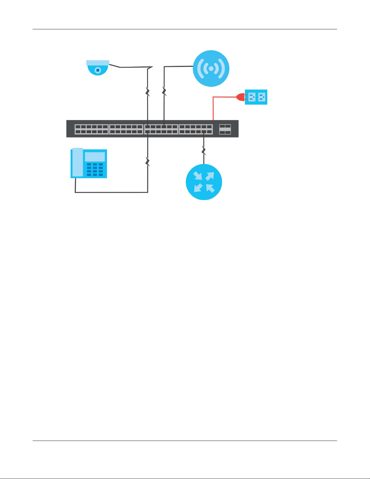
1.2.1 PoE Example Application
The following example figure shows a Switch supplying PoE (Power over Ethernet) to Powered Devices
(PDs) such as an IP camera, a wireless router, an IP telephone and a general outdoor router that are not
within reach of a power outlet.
GS1300 Series User’s Guide
5
Chapter 1 Getting to Know Your Switch
Figure 1 PoE Example Application
1.2.2 Backbone Example Application
The Switch is an ideal solution for small networks where rapid growth can be expected in the near future.
The Switch can be used standalone for a group of heavy traffic users. You can connect computers and
servers directly to the Switch’s port or connect other switches to the Switch.
In this example, all computers can share high-speed applications on the server. To expand the network,
simply add more networking devices such as switches, routers, computers, print servers etc.
GS1300 Series User’s Guide
6

Chapter 1 Getting to Know Your Switch
Figure 2 Backbone Example Application
1.2.3 Bridging / Fiber Uplink Example Application
In this example, the Switch connects different company departments (RD and Sales) to the corporate
backbone. It can alleviate bandwidth contention and eliminate server and network bottlenecks. All
users that need high bandwidth can connect to high-speed department servers via the Switch. You can
provide a super-fast uplink connection by using a Gigabit Ethernet/SFP port on the Switch.
Figure 3 Bridging / Fiber Uplink Example Application
GS1300 Series User’s Guide
7

Hardware Installation and
2.1 Installation Scenarios
This chapter shows you how to install and connect the Switch. See Table 1 on page 5 for a comparison
table of the hardware installation methods for each model.
The Switch can be:
• Wall-mounted on a wall.
• Rack-mounted on a standard EIA rack.
Note: It is recommended to ask an authorized technician to mount the Switch to a rack or
wall. See the Installation Requirements sections in this chapter to know the types of
screws and screw drivers for each mounting method.
CHAPTER 2
Connection
WARNING! Failure to use the proper screws may damage the unit.
Turn off the Switch (disconnect the power cables) before mounting the Switch.
WARNING! The surface of the Switch could be hot when it’s functioning.
Do NOT put your hands on it. You may get burned.
WARNING! This Switch is not suitable for use in locations where children
are likely to be present.
2.2 Wall Mounting
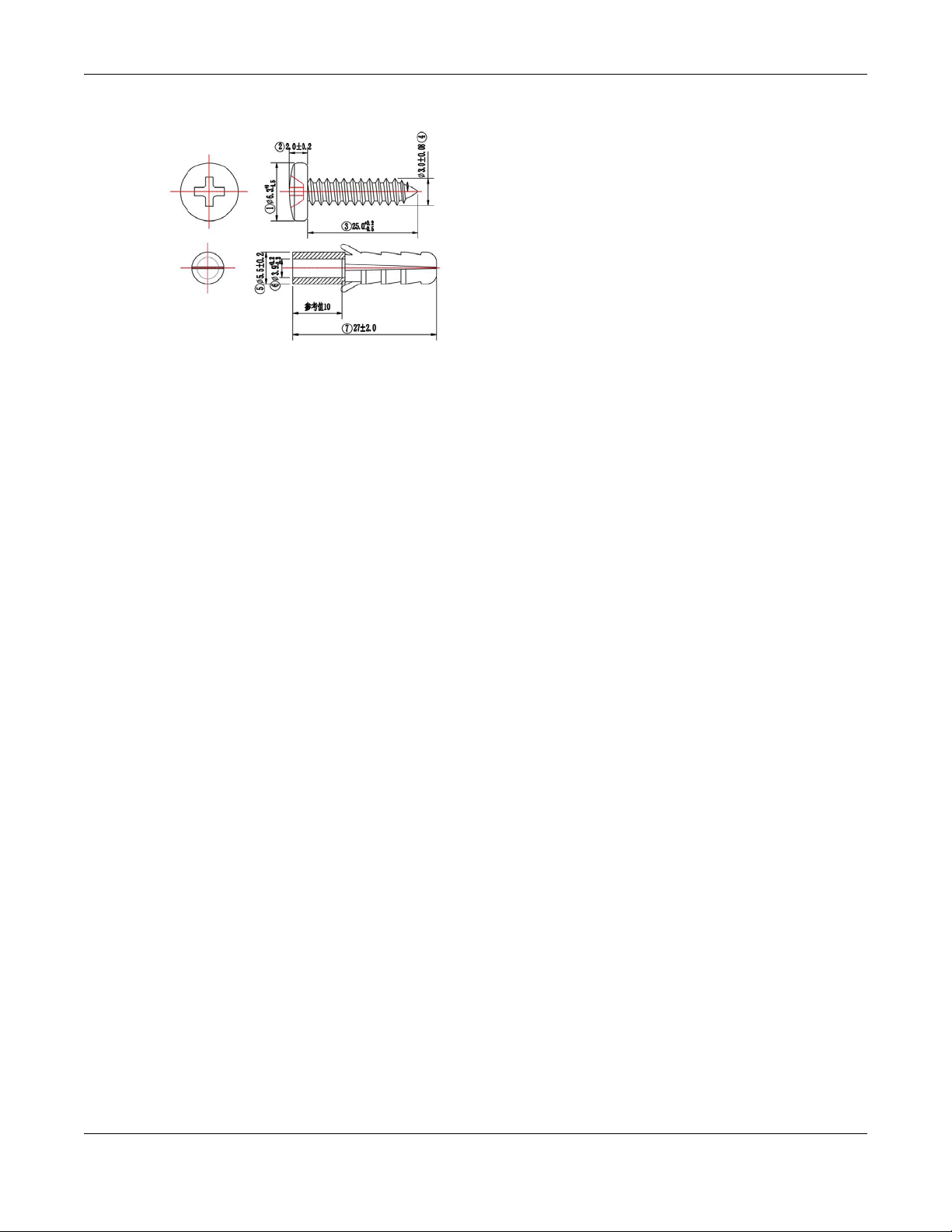
You may need screw anchors if mounting on a concrete or brick wall.
2.2.1 Installation Requirements
• Distance above the floor: At least 1.8 m (5.9 feet)
• Distance between holes: 78 mm (3.071 inches)
• Two M4 screws and a #2 Philips screwdriver
• Two screw anchors (optional)
GS1300 Series User’s Guide
8
Chapter 2 Hardware Installation and Connection
1 Select a position free of obstructions on a wall strong enough to hold the weight of the Switch.
2 Mark two holes on the wall at the appropriate distance apart for the screws.
WARNING! Be careful to avoid damaging pipes or cables located inside
the wall when drilling holes for the screws.
3 If using screw anchors, drill two holes for the screw anchors into the wall. Push the anchors into the full
depth of the holes, then insert the screws into the anchors. Do not insert the screws all the way in - leave
a small gap of about 0.5 cm.
If not using screw anchors, use a screwdriver to insert the screws into the wall. Do not insert the screws all
the way in - leave a gap of about 0.5 cm.
4 Make sure the screws are fastened well enough to hold the weight of the Switch with the connection
cables.
5 Align the holes on the back of the Switch with the screws on the wall. Hang the Switch on the screws.
Note: Make sure there is enough clearance between the wall and the Switch to allow
ventilation.
GS1300 Series User’s Guide
9

Chapter 2 Hardware Installation and Connection
WARNING! The Switch should be wall-mounted horizontally, and make sure
the front panel is facing down. The Switch's side panels with ventilation slots
should not be facing up or down as this position is less safe.
2.3 Rack Mounting
The Switch can be mounted on an EIA standard size, 19-inch rack or in a wiring closet with other
equipment. Follow the steps below to mount your Switch on a standard EIA rack using a rack-mounting
kit.
Note: Make sure there is enough clearance between each equipment on the rack for air
circulation.
2.3.1 Installation Requirements
• Two mounting brackets.
GS1300 Series User’s Guide
10
 Loading...