

Page 1

Installer/User Guide
274 Madison Avenue
New York, NY 10016 • USA
212-679-0050 (Fax) 212-679-0040
www.RackitTechnology.com
Page 2

Paradigm Installer/User Guide
Page 3

Installer/User Guide
274 Madison Avenue
New York, NY 10016 • USA
212-679-0050 (Fax) 212-679-0040
www.RackitTechnology.com
©2000 Rackit Technology Corporation. All rights reserved.
IBM, PC, PC/AT and PS/2 are registered trademarks of International Business Machines Corporation.
Microsoft and Kensington are registered trademarks of their respective companies. Logitech, Mouseman and
Trackman are trademarks of Logitech, Inc. IntelliMouse is a trademark of Microsoft Corporation.
Page 4

Paradigm Installer/User Guide
FCC Notification
Warning: Changes or modifications to this unit not expressly approved by
the party responsible for compliance could void the user's authority to
operate the equipment.
Note: This equipment has been tested and found to comply with the limits
for a Class A digital device, pursuant to Part 15 of the FCC Rules. These
limits are designed to provide reasonable protection against harmful
interference when the equipment is operated in a commercial environment.
This equipment generates, uses and can radiate radio frequency energy
and, if not installed and used in accordance with the instruction manual,
may cause harmful interference to radio communications. Operation of
this equipment in a residential area is likely to cause harmful interference
in which case the user will be required to correct the interference at his
own expense.
Canadian Notification
This digital apparatus does not exceed the Class A limits for radio noise
emissions from digital apparatus set out in the Radio Interference
Regulations of the Canadian Department of Communications.
Le present appareil numerique n'emet pas de bruits radioelectriques les
limites applicables aux appareils numeriques de la class A prescrites dans
le Reglement sur le brouillage radioelectrique edicte par le ministere des
Communications du Canada.
Page 5

Table of Contents
Chapter 1 - Product Overview
Feature Overview ...................................................................................................................................... 1
Compatibility ............................................................................................................................................. 3
Chapter 2 - Installation
Basic Install ................................................................................................................................................ 5
Advanced Install ....................................................................................................................................... 8
Chapter 3 - Basic Operations
Overview ...................................................................................................................................................... 9
Keyboard Control .................................................................................................................................. 10
Keyboard Switching ............................................................................................................................. 11
System Control & Maintenance ....................................................................................................... 12
Chapter 4 - On-Screen Display Operations
Activating OSD ...................................................................................................................................... 13
The OSD Window .................................................................................................................................. 14
The Command Menu ........................................................................................................................... 15
Basic Channel Maintenance ............................................................................................................. 16
The ID Window ...................................................................................................................................... 18
Administrator Functions ..................................................................................................................... 20
Chapter 5 - Channel Scanning
Choosing a Scanning Method .......................................................................................................... 23
Setting the Scanning Order ............................................................................................................... 24
Turning Scanning On and Off........................................................................................................... 24
Setting the Scanning Dwell Time .................................................................................................... 25
Scanning and Security ......................................................................................................................... 26
Chapter 6 - Appendices
A: Specifications .................................................................................................................................... 27
B: Pairing .................................................................................................................................................. 28
C: Troubleshooting................................................................................................................................ 34
D: Problem Report................................................................................................................................. 39
Page 6
Paradigm Installer/User Guide
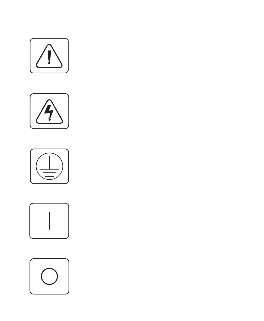
INSTRUCTIONS: The exclamation point within an equilateral triangle is intended to alert the user to the presence of important operating and maintenance (servicing) instructions in the literature accompanying the appliance.
DANGEROUS VOLTAGE: The lightning flash with arrowhead symbol, within an equilateral triangle, is intended to alert the user to the
presence of uninsulated “dangerous voltage” within the product's
enclosure that may be of sufficient magnitude to constitute a risk of
electric shock to persons.
PROTECTIVE GROUNDING TERMINAL: A terminal which must be
connected to earth ground prior to making any other connections to
the equipment.
POWER ON: This symbol indicates the principle on/off switch is in
the on position.
POWER OFF: This symbol indicates the principle on/off switch is in
the off position.
Page 7

1
Feature Overview
The Paradigm allows you to control up to 64 PCs with one keyboard,
monitor and mouse. Each computer can be up to 30 feet away from the
Paradigm. The Paradigm works with IBM PC/AT and PS/2 systems, and
100% compatible machines with support for VGA, SVGA, XGA and XGA-II
video. PS/2 keyboard and PS/2 mouse peripherals are supported through
the rear of the unit.
Product Overview
Expansion for up
to 64 computers
AutoBoot
technology
On-screen display
capability
Advanced security
for total control
over system access
IntelliMouse
support
A Paradigm unit will support from one to eight attached PCs, or channels.
If more than eight channels are needed, multiple units can be cascaded
together for expansion. Up to 2 tiers of units can be connected for a total
of 64 attached computers in one system.
The AutoBoot feature boots all attached servers during initial power-up or
after a power failure. PCs are booted transparently without operator
intervention, and may be powered-up one-at-a-time or all at once. When
the power stabilizes, a channel may be selected. The first available channel
is automatically selected upon power-up of the base Paradigm.
Configure and control your Paradigm with on-screen menuing! Name
your computer channels anything you wish, then select the desired
computer from an easy-to-use menu. Secondary menus let you configure
and initiate channel scanning and other system features.
Use the advanced bi-level security feature to configure and control server
access for every type of user in the system. The administrator has full
access privileges; individual users can have viewing or viewing/editing
capability for each attached server.
The Paradigm offers full support for the Microsoft IntelliMouse.
1
Page 8
Paradigm Installer/User Guide
Push-button &
keyboard switching
“Keep Alive”
feature
Built-in scanning
capabilities
Status indicator
LEDs
In addition to using the on-screen menus, you can switch computer
channels with a simple keyboard sequence.
Paradigm’s “Keep Alive” feature allows attached servers to power the unit
in the event of a Paradigm power failure. This prevents attached PCs from
locking up and keeps you from losing time and data.
A built-in scanning feature allows you to automatically monitor, or scan,
your PCs without intervention. When keyboard activity is detected,
scanning is suspended until all activity stops. Scanning then resumes with
the next channel in sequence.
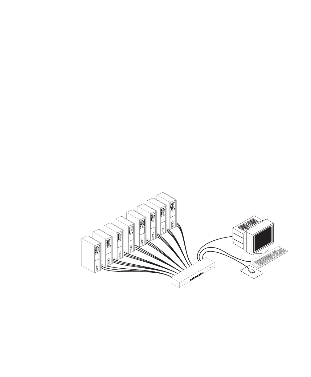
A typical Paradigm configuration is shown below.
S
U
T
A
/
T
P
S
E
T
N
S
A
C
S
H
G
F
E
D
C
B
A
2
Page 9

Compatibility
Product Overview
PS/2 peripherals
XGA/XGA-II
support
The Paradigm requires a PS/2 mouse and keyboard. The following mice
are known to be compatible:
IBM PS/2-style Logitech Trackman
Kensington Logitech Mouseman (PS/2)
Microsoft IntelliMouse
Other manufacturers' mice may operate with the Paradigm. If you
experience problems using an untested mouse, contact Rackit Technical
Support with the manufacturer and model number of the mouse.
If you wish to use XGA or XGA-II video, you will need to purchase an
adaptor available through Rackit.
3
Page 10

Paradigm Installer/User Guide
Page 11
2
Basic Install
Installation
1. Power-down all computers that will be part of your Para-
digm system.
Connecting your Peripherals
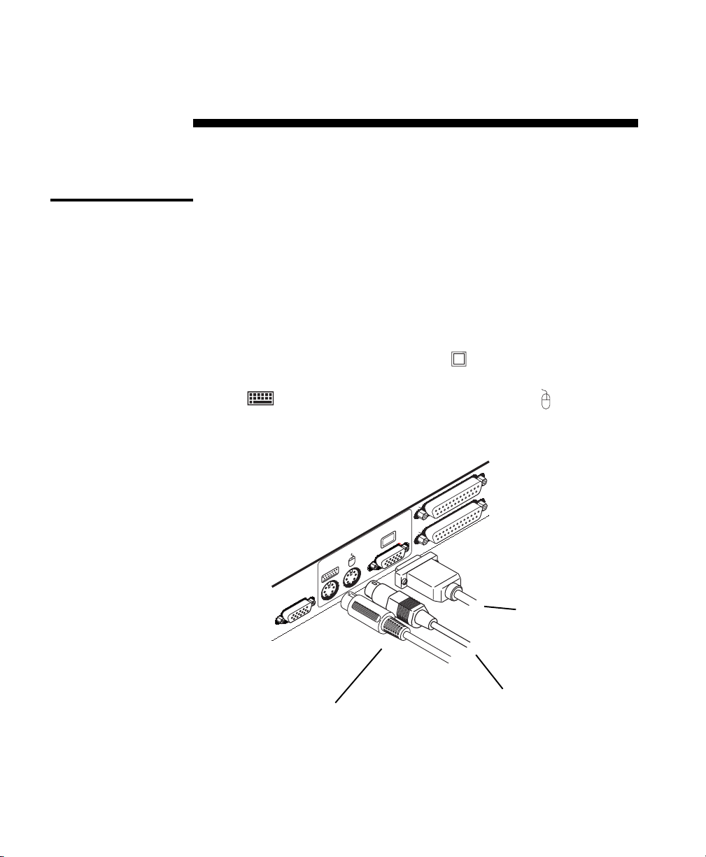
2. Locate your PS/2 keyboard, VGA video monitor and PS/2 mouse.
3. Plug your VGA monitor cable into the port on the back of your
Paradigm in the user console section. Plug your PS/2 keyboard cable
into the
port and your PS/2 mouse cable into the port.
A
SETUP
PS/2 KEYBOARD CABLE
USER
E
VGA MONITOR CABLE
PS/2 MOUSE CABLE
5
Page 12
Paradigm Installer/User Guide
Connecting Computers to the Paradigm
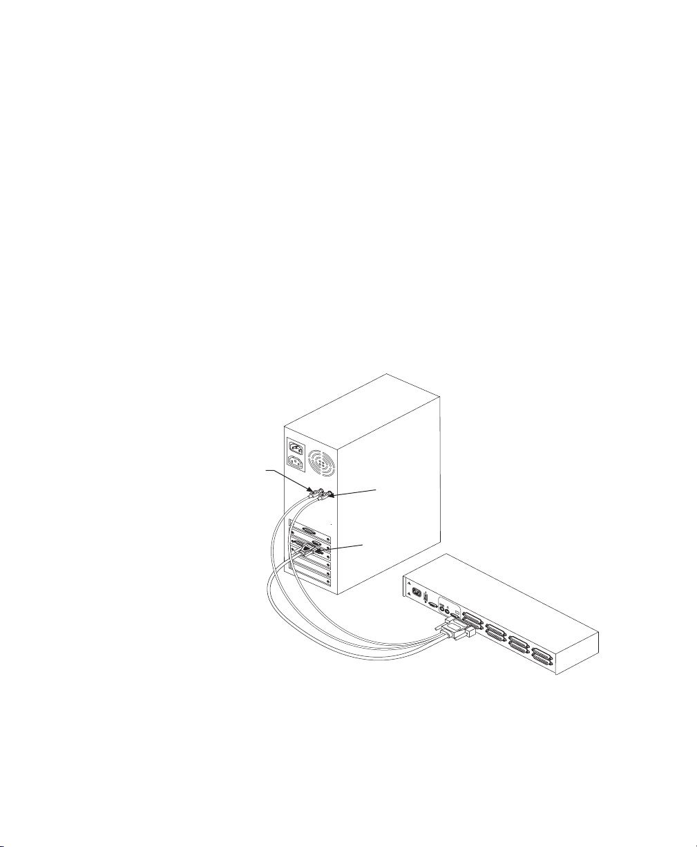
4. Locate your first computer interface cable. It will have a 25-pin “D”
connector at one end. Plug this cable into any lettered channel port on
the rear of the Paradigm. The other end of the input cable will have
five connectors: a 15-pin “HDD” connector for your video, a 5-pin DIN/
6-pin miniDIN connector for an AT or PS/2 keyboard connection, and
a 9-pin serial/6-pin miniDIN connector for a serial or PS/2 mouse
connection. The PS/2 mouse connector is designated by a yellow band
or mouse icon.
Use only the keyboard and mouse connectors that are appropriate for your PC, and leave the others unconnected.
Plug these connectors into the matching ports on your computer.
MOUSE PORT
KEYBOARD
PORT
VIDEO
PORT
1
0
0
2
4
0
V
~
,
.
1
a
,
5
0
/
8
0
H
z
T
2A, 250 V
AC
POWER
P
A
T
E
U
N
S
T
E
P
R
E
N
D
I
N
G
H
G
F
E
D
C
B
A
M
A
D
E
I
N
U
S
A
5. Locate your next computer interface cable. Repeat step 4 until all
computers are properly attached to the Paradigm.
6
Page 13
Installation
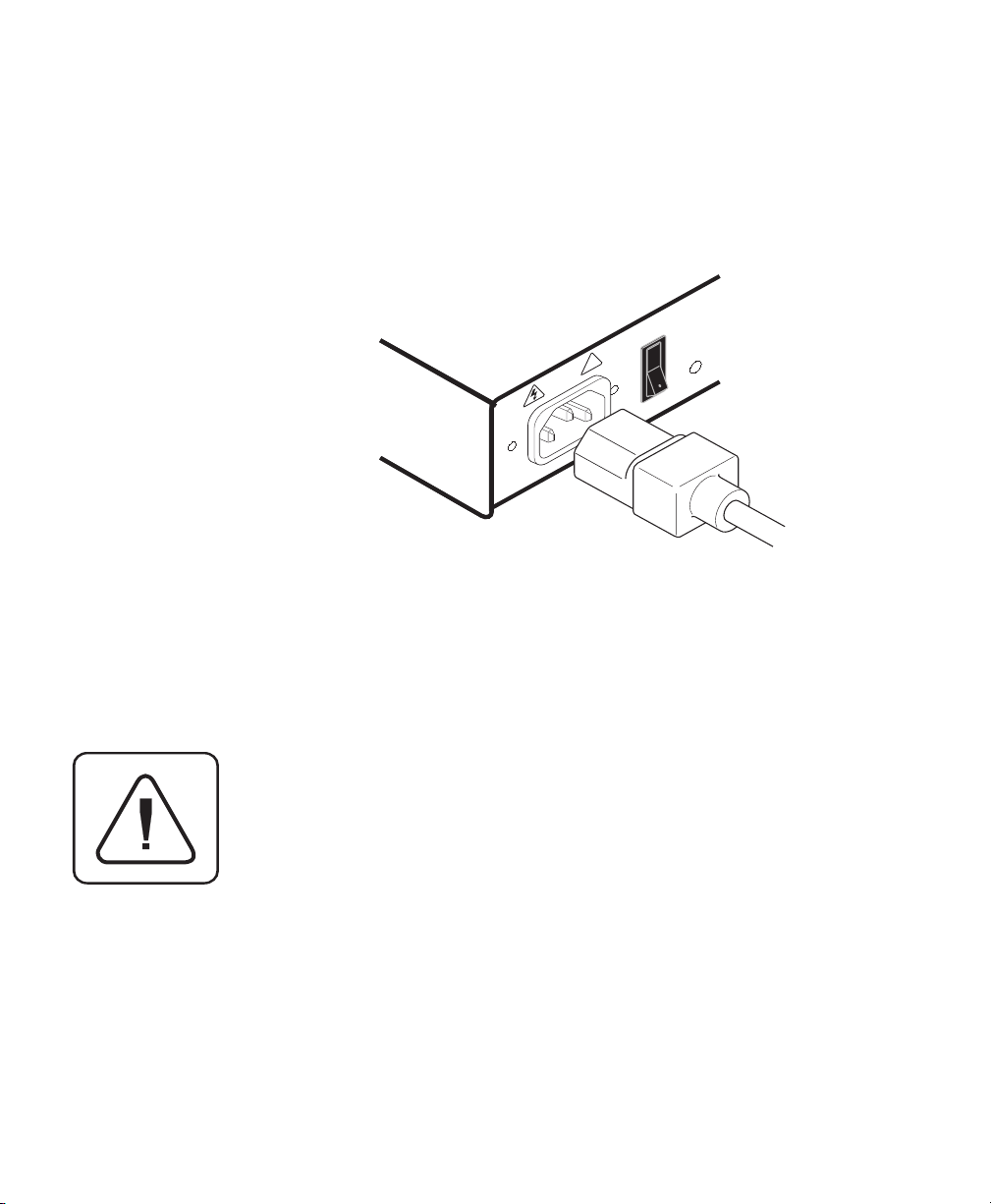
6. Locate the power cord that came with your Paradigm unit. Plug it into
the IEC power connector on the Paradigm. Make sure that the power
switch is off, then plug the other end of the power cord into an
appropriate AC wall outlet. This outlet must be near the equipment
and easily accessible to allow for unplugging prior to any servicing of
the unit.
1
!
0
100-240V , .1A, 50/60 Hz
7. Power-up your Paradigm unit first, then all attached computers.
The Paradigm and all attached computers should be
powered-down before servicing the unit. Always disconnect
the power cord from the wall outlet.
7
Page 14
Paradigm Installer/User Guide
Advanced InstallAdvanced Install
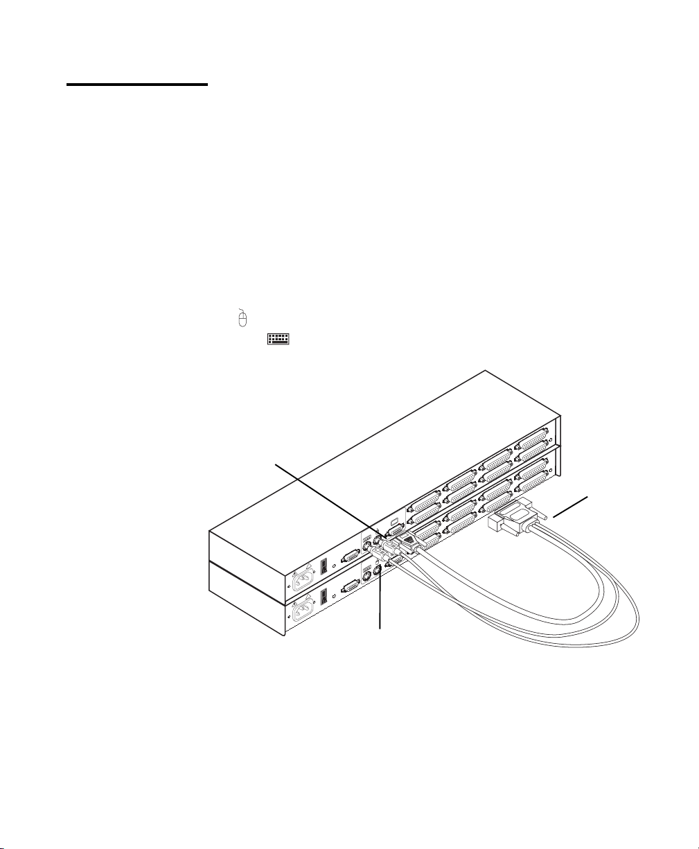
Attaching Multiple Paradigm Units
1. Follow steps 1-6 of the Basic Install section.
2. Plug the 25-pin “D” connector of your computer interface cable into
any available channel port on the rear of your base Paradigm unit.
3. Plug the 15-pin video connector on the other end of the cable into the
port labeled on your first cascading Paradigm unit. Plug the PS/2
mouse connector, designated by a yellow band or mouse icon, into
the
into the
used for cascading.
port. Plug the remaining 6-pin miniDIN keyboard connector
port. The 9-pin serial and 5-pin DIN connectors are not
CASCADING UNIT
MADE IN USA
PS/2 MOUSE
CONNECTOR
P
ETU
S
1
!
0
P
ETU
S
z
, 50/60 H
1
, .1A
PATENT PENDING
100-240V
!
0
z
, 50/60 H
, .1A
PATENT PENDING
100-240V
PS/2 KEYBOARD CONNECTOR
B
F
A
B
E
R
E
S
U
R
E
S
U
F
A
E
D
H
C
D
G
H
C
G
BASE UNIT
MADE IN USA
VGA VIDEO
CONNECTOR
4. Repeat steps 2-3 for every cascaded Paradigm unit in your system.
5. Power-up your Paradigm unit(s) first, then all attached computers.
8
Page 15
3
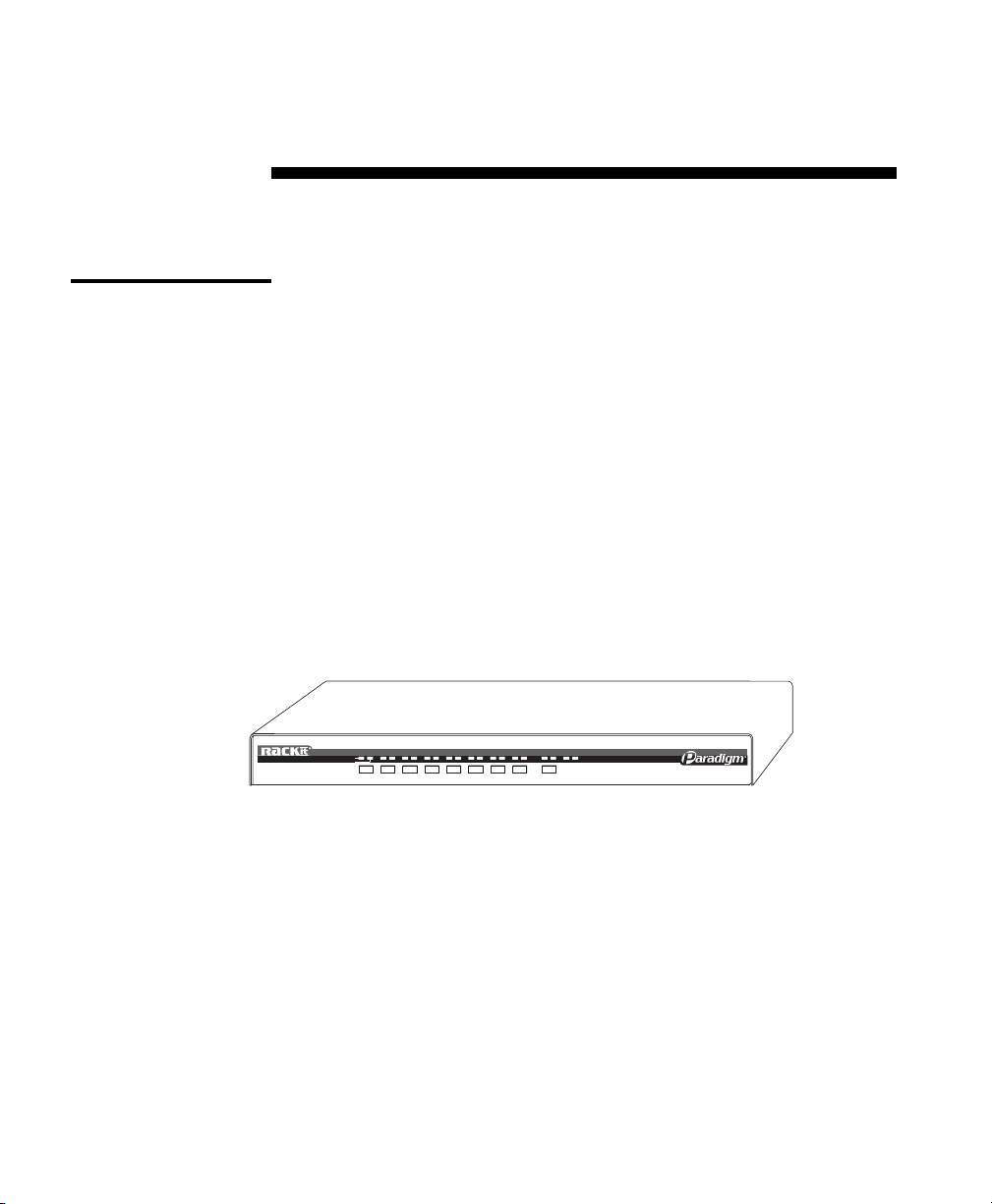
Overview
Basic Operations
Your Paradigm may be operated in a non secure (no password required)
or secure (password required) mode. All units ship defaulted to the nonsecure mode. For information on implementing password security see the
“Administrator Functions” section of chapter 4.
PCs may be powered-up one-at-a-time or all at once. No operator intervention
is required during booting. When the system stabilizes, a PC may be selected
via the on-screen display menu or keyboard hot-key sequence.
SELECTED
C
B
A
ON-LINE
DEF
9
STEP/
G
H
SCAN STATUS
Page 16

Paradigm Installer/User Guide
Keyboard Control
The following conventions appear throughout this chapter to illustrate
commands for operating the Paradigm. Whenever you see one of the
symbols listed on the left side of the table, substitute the corresponding
steps or values listed on the right side of the table.
Convention Key Sequence or Value
<CM> 1. Press and hold down the ‘Num Lock’ key.
<Enter> Press the ‘Enter’ or ‘Return’ key. The <Enter> command is used to
Enter Command Mode:
2. Press and release the minus (-) key on the numeric keypad.
3. Release the ‘Num Lock’ key.
Note: For alternate hot-key sequences, see ‘System Control &
Maintenance’ later in this chapter.
execute an instruction and exit from Command Mode.
Addr
<ESC> Press the ‘Escape’ key. The <ESC> command is used to exit
The letters over the push-buttons on your Paradigm are your PCs'
addresses. Enter the letter, A-H, for the PC you're selecting. For
cascaded systems, enter the address of the base unit first.
Example
your base unit. To access the PC at channel C of this second
(cascaded) unit, enter BC.
Command Mode without executing an instruction.
: You have a Paradigm unit cascaded from channel B of
10
Page 17
Keyboard
Switching
Basic Operations
One of the ways to change the active channel in a non-secured Paradigm
system is by entering a short sequence of keystrokes on the keyboard. This
is called keyboard, or hot-key, switching.
Note: Hot-key switching is only available in the default non-secure state.
For more information on secure versus non-secure operation, see
the ‘Administrator Functions’ section of Chapter 4.
The first set of keystrokes places your system in Command Mode. As long
as you are operating in Command Mode, whatever you type will be
interpreted as channel switch commands until the Enter or the Escape key
is pressed to terminate Command Mode. None of the keystrokes entered
will be forwarded to the attached computer until you exit Command Mode.
Next, enter the address
(Addr)
for the channel you wish to select.
Press Enter to accept the new channel. The following command line
shows the proper format used to switch your active channel via keyboard.
Key Sequence Action
<CM>Addr<Enter> Selects an active channel via keyboard.
Below is a sample of a keyboard switching session, with an accompanying
explanation for each step.
Key Sequence Action
1.<CM>E<Enter> Selects Channel E on the base unit as the active channel.
2.<CM>CF<Enter> Selects the Paradigm attached to channel C on the base unit,
then selects channel F on the cascaded unit.
3.<CM>G<Enter> Selects Channel G on the base unit as the active channel.
4. <CM>BA<ESC> Exit Command Mode. The instruction is not executed. Channel
G is still the active channel.
11
Page 18

Paradigm Installer/User Guide
System Control &
Maintenance
The following commands are used for system control and maintenance.
Enter the command sequences to perform the actions described in the
table below.
Key Sequence Action
<CM>Kn<Enter> Sets the keyboard scan set where n is a scan set number 1-3.
<CM>MR<Enter> If you hot-plug your mouse cable, you may experience a loss of
<CM>MW<Enter> If you hot-plug your mouse cable, you may experience a loss of
<CM>AV<Enter> Displays the current firmware version of the processors inside
<CM>H1<Enter> Changes the hot-key sequence to the default:
<CM>H2<Enter> Changes the hot-key sequence to the 1st alternate:
<CM>H3<Enter> Changes the hot-key sequence to the 2nd alternate:
<CM><CM>
<CM>ZM
<CM><CM>
mouse signal. Use this command to restore the signal if you are
using a PC with a standard PS/2 mouse driver.
mouse signal. Use this command to restore the signal if you are
using a PC with a Microsoft IntelliMouse driver.
your Paradigm unit. You must be either at a DOS prompt or in a
text editor/word processor to view this information.
1. Press and hold down the ‘Num Lock’ key.
2. Press and release the minus (-) key on the numeric keypad.
3. Release the ‘Num Lock’ key.
1. Press and hold down the ‘Num Lock’ key.
2. Press and release the asterisk (*) key on the numeric keypad.
3. Release the ‘Num Lock’ key.
1. Press and hold down the ‘Control’ key.
2. Press and release the tilde (~) key.
3. Release the ‘Control’ key.
<Enter><Enter>
<Enter> Use this command to resynchronize the mouse after a device or
<Enter><Enter>
computer hot-plug. Repeat, if necessary, until synchronization is
re-established.
Note: Using this command while the mouse is operating
correctly will cause the mouse to lose sync.
12
Page 19

On-Screen Display
4
Activating OSD
Operations
Activate on-screen display (OSD) by pressing either of the keyboard Control
keys twice within one second. In nonsecure mode, this brings up the main
OSD Window, “Administrator Channel List”.
In secure mode, activating OSD will bring up the “User Login” window.
Type in your user name and press Enter. The system administrator
should login as “Admin”, “Root” or “Administrator”. If the user name is
valid, the password window will appear. Type your password and press
Enter. This will bring up your “Channel List”. If there is no keyboard
activity, the login window will timeout after 5 minutes and go to screen
saver. Press any key to restore the login prompt.
Note: All Paradigm units ship in the default non-secure state. For more
information on secure versus non-secure operation, see the section
‘Administrator Functions’.
13
Page 20
Paradigm Installer/User Guide
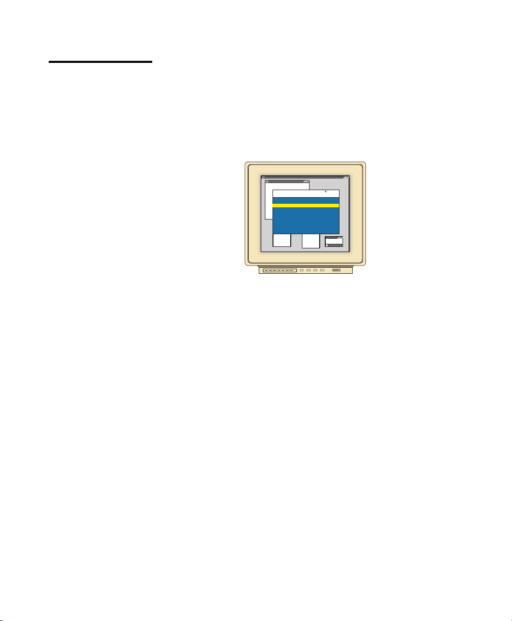
The OSD Window
This window lists all named channels in your Paradigm system. They
will be listed alphabetically with their channel addresses and access
status beside them. When in secure mode, only the channels that are
accessible to the logged in user will be listed. (See the section
‘Administrator Functions’ for more information.)
Use your up and down arrow keys, the page up and down keys, or your
mouse to select a channel. Move immediately to the top or bottom of the
list with the home and end keys. Press a letter while in the main OSD
Window, and the Highlight Bar moves to the first channel name beginning
with that letter. Press the letter repeatedly to scroll through all channels
that begin with that letter from top to bottom. Press Enter to make the
switch. To exit the OSD Window without changing channels, press Esc.
To manually logout when in secure mode, press F10.
Program Manager
Rackit Control Panel
Administrator Channel List
Name Access
Accounting F
Engineering
Jene's PC
Mail Server
Pam's PC
Shop Floor
Address
E
C
A
B
D
K
K
V K
V K
V K
K
F10-Logout
THE MAIN OSD WINDOW
14
Page 21
The Command
Menu
On-Screen Display Operations
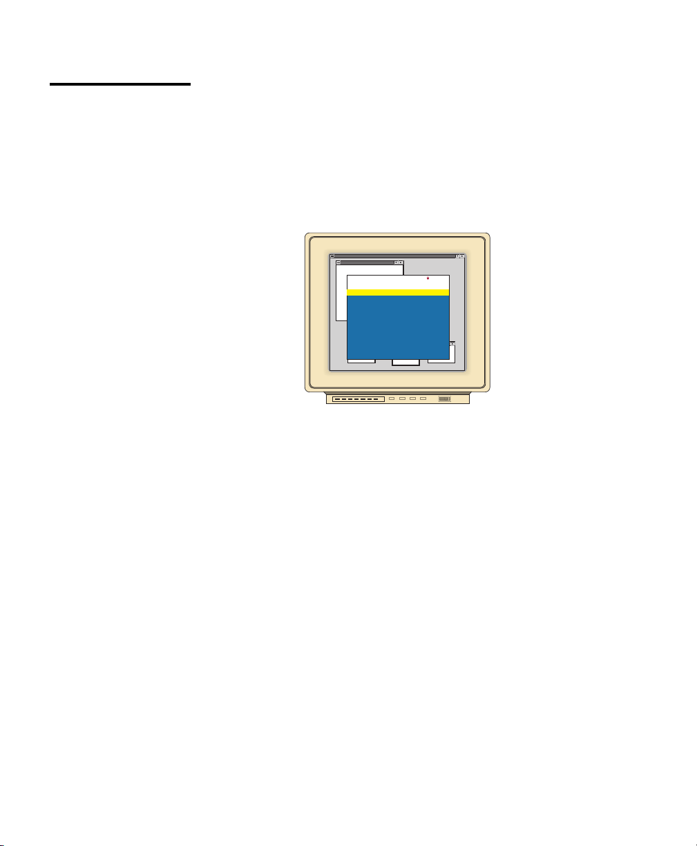
Once you have activated the main OSD Window, you can open the Command
Menu by either pressing the Control key twice or by typing ALT-M.
The Command Menu options are selected in the same manner as channels
in the OSD Window. Scroll the Highlight Bar up and down and press Enter
when your selection is highlighted.
Program Manager
Rackit Control Panel
Administrator Command Menu
Channel Maintenance
Administrator Functions
Turn Scanning ON
Scanning Order
Sequential Scan Dwell Time
Reset Standard Mouse/Keyboard
Reset Wheel Mouse/Keyboard
Version Information
ENTER-accept ESC-previous
THE COMMAND MENU
Games
If you are operating in non-secure mode or are the system administrator,
you will have several options that do not appear in the User level Command
Menu: Channel Maintenance, Administrator Functions and Sequential
Scan Dwell Time. Channel Maintenance and Administrator Functions are
both covered in separate sections in this chapter. Scanning is covered in
Chapter 5.
If you experience a loss of mouse signal while using the Paradigm, select
the ‘Reset Standard Mouse/Keyboard’ option from this menu for a PC with
a standard mouse driver or ‘Reset Wheel Mouse/Keyboard’ if you are using
a PC with a Microsoft IntelliMouse driver. This will reset and in most cases
restore your mouse signal. These commands are equivalent to the
<CM>MR<Enter> and <CM>MW<Enter> keyboard command listed in
the ‘System Control & Maintenance’ section of this manual.
Choose the option ‘Version Information’ to display on your monitor the
current version level of your OSD firmware. Press the Esc key to clear this
information from your screen.
15
Page 22
Paradigm Installer/User Guide
Basic Channel
Maintenance
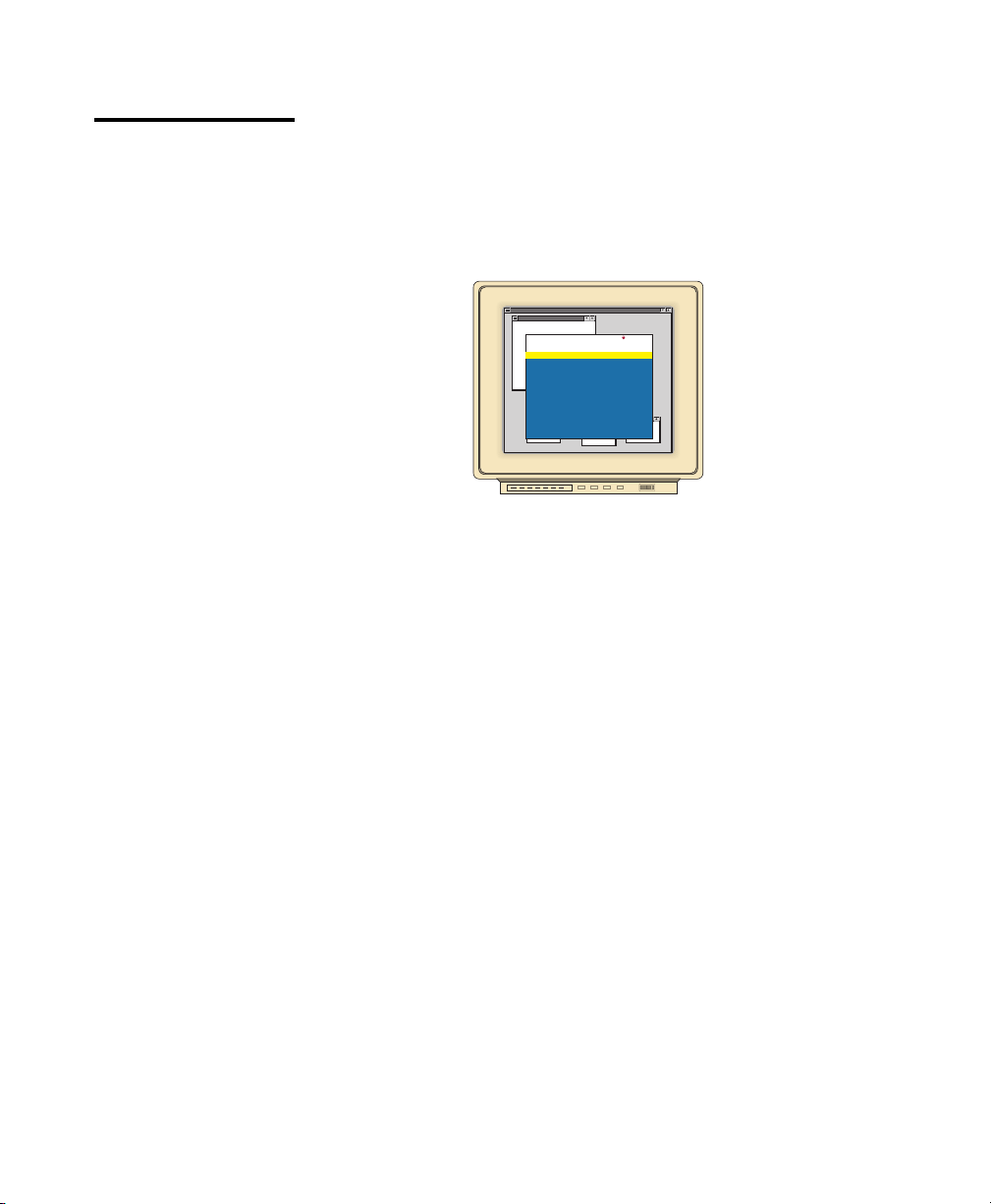
The Channel Maintenance Menu is accessed from the Administrator
Command Menu, and is available if you are operating in non-secure mode
or if you are the system administrator. Here you can add, delete or alter
individual channels.
Adding New Channels (base unit only)
Program Manager
Rackit Control Panel
Configure Channel
Add Channel
Delete Channel
Change Channel Name
Change ChannelAddress
Dwell Time For ID window
Options For ID window
Alpha Scan Dwell Time
Games
ENTER-accept ESC-previous
THE CHANNEL MAINTENANCE WINDOW
1. Select ‘Add channel’ from the Channel Maintenance Menu. Type in a
new channel name, up to 14 characters long, and press Enter.
2. Type in the channel letter for the PC you are naming and press Enter.
3. When prompted for another cascade level, type N and press Enter.
Press Esc at any point to exit this operation without adding the channel.
Adding New Channels (with a cascaded unit)
1. Select ‘Add channel’ from the Channel Maintenance Menu. Type in a
new channel name, up to 14 characters long, and press Enter.
2. Type in the Paradigm channel letter that corresponds to the port that
the second cascaded Paradigm unit is attached to and press Enter.
16
Page 23

On-Screen Display Operations
3. When prompted for another cascade level, type Y and press Enter.
4. Enter the letter that corresponds to the computer port on the cascaded
Paradigm you are adding and press Enter.
5. When you have finished adding levels (up to two total), type N when
prompted for another cascade level and press Enter.
Press Esc at any point to exit this operation without adding the channel.
Deleting an Existing Channel
1. Highlight the channel you wish to delete in the main OSD Window.
2. Press the Control key twice or type Alt-M to access the Command Menu.
3. Select ‘Channel maintenance’ from the Command Menu.
4. Choose the ‘Delete channel’ option.
5. Type Y or N at the prompt to confirm the deletion and press Enter.
Changing Channel Names and Addresses
1. Highlight the channel you wish to change in the main OSD Window.
2. Press the Control key twice or type Alt-M to access the Command Menu.
3. Select ‘Channel maintenance’ from the Command Menu.
4. Choose the appropriate option.
5. Enter the new channel name or address and press Enter to accept.
Press Esc at any point to exit this operation without saving the changes.
17
Page 24

Paradigm Installer/User Guide
The ID Window
The ID Window appears when you change channels and displays the
name of the selected channel. This window can be individually configured
for each channel in your system. The characteristics of the ID Window
can be changed from the Channel Maintenance Menu. This option is
only available if you are operating in non-secure mode or if you are the
system administrator.
Changing the Size, Color and Position of the ID Window
1. From the main OSD Window, press the Control key twice or type Alt-M
to access the Command Menu.
2. Select ‘Channel maintenance’ from the Command Menu.
3. Choose the option ‘Options for ID window’.
Follow the procedures outlined in the table below to change the size, color
or position of your ID Window.
Operation Procedure
Move the ID Window Use the arrow keys or mouse to move the ID
Window's position on the monitor. If the window
flickers but does not move, continue tapping the
arrow keys until it moves back into range.
Change window background color Press the <PAGE UP> key to cycle through the
available window background colors.
Change text color Press the <PAGE DOWN> key to cycle through
the available text colors.
Change window size Use the (+) and (-) keys to change the length of
the ID Window.
4. Press Enter to accept the changes or press Esc to exit the menu
without saving the changes.
18
Page 25

On-Screen Display Operations
On-Screen Display Operations
Setting the ID Window Dwell Time
This menu selection lets you set the time that the ID Window remains on
screen after a channel switch. Each channel can be configured
independently. The default time is set for 5 seconds.
1. From the main OSD Window, press the Control key twice or type Alt-M
to access the Command Menu.
2. Select ‘Channel maintenance’ from the Command Menu.
3. Choose the option ‘Dwell time for ID window’.
4. Enter a number between 0-255 seconds. Entering 0 disables the ID
Window. Entering 255 allows the ID Window to stay on screen the
entire time the channel is active.
19
Page 26

Paradigm Installer/User Guide
Administrator
Functions
The Administrator Functions Menu is accessed from the Command Menu.
Here, you can create an administrator password, set a system logout time
and create individual user logins with specific access and privileges. This
menu is only used if you are running your system in secure
mode. If you configure an administrator password from this menu, your
system will then be in secure mode. A lock symbol will appear to the right of
the menu headings to indicate secure operation. If you wish to keep your
system in the default non-secure mode, return to the Command Menu. For
the differences between secure and non-secure modes, see below.
Differences between Secure and Non-Secure Operating Modes
Administrator Password
Entering an administrator password places your system in secure mode.
Non-secure systems do not use passwords. To return your system to the
default of non-secure mode, simply delete the administrator password.
When the administrator password is enabled, user passwords must also be
entered or the switch will not be completely secure. The default for users
is no password. Simply hit the enter key at the prompt.
Logout Capability
You have the option of automatically logging out of the system after an
administrator defined period of inactivity. Timeout values can be set from
0 to 60 minutes. A value of 0 keeps the user logged in continuously. When
the timeout is reached, the current channel is deselected and the display
goes to screen saver mode. Users must login again to access system
computers. This option is only available in secure mode.
Multiple User Logins
You can create up to four user logins in addition to the system
administrator. Use these logins to configure and control server access for
every type of system user. The administrator has full access privileges;
additional users can have viewing or viewing with keyboard and mouse
control capability for each attached server. This option is only available in
secure mode.
20
Page 27

On-Screen Display Operations
Hot-Key Channel Selection
While in secure mode, all hot-key channel selection methods are disabled.
(This also includes use of the Rackit Remote Switch Panel (RSP)) All other
hot-key commands remain operational to the administrator only. In nonsecure mode hot-key commands function normally.
Creating the Administrator Password
1. Press the Control key twice or type Alt-M to access the Command Menu.
2. Select ‘Administrator Functions’ from the Command Menu.
3. Select ‘Administrator Password’ from the Administrator Menu.
4. Type your password and press Enter. (The password is not case
sensitive.)
5. Repeat entry of the password for confirmation.
CAUTION: Security is enabled once the password has been
created. Store a copy of your password in a safe place.
You should now see the option ‘F10 - Logout’ at the bottom of your main
OSD Window and a lock symbol to the right of the menu headings.
Setting the Administrator Logout Time
1. Press the Control key twice or type Alt-M to access the Command Menu.
2. Select ‘Administrator Functions’ from the Command Menu.
3. Select ‘Administrator Logout Time’ from the Administrator Menu.
4. Enter the number of minutes you wish to pass without keyboard/
mouse activity before the administrator is automatically logged out of
the system. The default of 0 keeps the administrator logged on
continuously; 60 is the maximum setting.
21
Page 28

Paradigm Installer/User Guide
Setting Up Additional Users
1. Press the Control key twice or type Alt-M to access the Command Menu.
2. Select ‘Administrator Functions’ from the Command Menu.
3. Select ‘Setup User 1’ from the Administrator Menu.
4. Choose the ‘Name’ sub-menu and enter the name for this user.
5. Choose the ‘Password’ sub-menu and enter the password and confirm
it for this user. (Passwords are not case sensitive.)
6. Choose the ‘Access’ sub-menu. Here, you will see a listing of all attached
servers in the channel list. For each server, choose a level of access for
this user by selecting one of the function keys listed on the screen: F5 for
no access, F6 for video only or F7 for video and keyboard/mouse
capability. The default is set for full access. All changes go into effect as
soon as they are made. Press Enter when you have completed your
configuration.
7. Choose the ‘Logout Time’ sub-menu. Enter a value in minutes for this
user’s logout time. A value of 0 keeps the user logged on continuously;
60 is the maximum setting. The default is set for 5 minutes.
8. Press Enter to accept your selections and repeat steps 3-8 for each
remaining user.
22
Page 29

5
Choosing a
Scanning Method
Paradigm's scanning feature allows you to automatically monitor, or
scan, your computer channels without intervention. When keyboard
activity is detected, scanning is suspended until all keyboard activity
stops. Scanning then resumes with the next channel in sequence. Mouse
activity will not affect scanning in any way. The length of time each
channel remains on the screen, or dwell time, is configurable and can be
changed at any time.
There are two ways to scan through the channels in your Paradigm
system, either sequentially or alphanumerically.
Scanning sequentially allows you to view each of your active channels in
the order that they are attached to the Paradigm. The amount of time each
channel remains on the screen, or dwell time, is configurable and is the
same for all channels.
Channel Scanning
Scanning alphanumerically allows you to scan all your channels in
alphanumeric order according to the channel list in the main OSD Window.
With this scan method, you can adjust the dwell time for each channel or
omit a channel from the scan sequence completely.
Choose whichever method is most appropriate for your configuration.
23
Page 30
Paradigm Installer/User Guide
Setting the
Scanning Order
1. From the main OSD Window, press the Control key twice or type
2. Choose ‘Scanning order’ from the menu.
3. Select either ‘Sequential order’ or ‘Alphanumeric order’.
4. Press Enter.
Turning Scanning
On and Off
From the OSD menu.
1. From the main OSD Window, press the Control key twice or type
Alt-M to access the Command Menu.
Alt-M to access the Command Menu.
2. Select ‘Turn scanning ON’ or ‘Turn scanning OFF’ from the menu.
This is a toggle option - only one scanning option will show on the
menu at any one time.
3. Press Enter.
By keyboard hot-key sequence (System Administrator or
non-secure mode only)
The following key sequences control scanning.
Key Sequence Action
<CM>SG<Enter> Enables the scan Go command.
<CM>SH<Enter> Enables the scan Halt command.
24
Page 31

Setting the
Scanning Dwell
Time
(System
Administrators and
non-secure mode
users.)
Channel Scanning
For Sequential Scanning
1. From the main OSD Window, press the Control key twice or type
Alt-M to access the Command menu.
2. Choose the option ‘Sequential Scan Dwell Time.’
3. Enter a number between 2-60 seconds. The value you enter will be
the dwell time for each active channel in the system.
For Alphanumeric Scanning
1. Highlight the channel that you wish to configure in the main
OSD Window.
.
2. Next, press the Control key twice or type Alt-M to access the
Command Menu.
3. Select ‘Channel Maintenance’ from the Command Menu.
4. Choose the option ‘Alpha Scan Dwell Time’.
5. Enter a number between 0-255 seconds. Enter 0 to skip a channel
during scanning.
25
Page 32

Paradigm Installer/User Guide
Scanning and
Security
In non-secure mode, you may scan your channels either
alphanumerically according to your channel list or sequentially through
all attached servers. Note that with sequential scanning, you will pause
at every active channel, regardless of whether that channel has been
added to the channel list or not.
In secure mode, you will only scan through channels that appear on
the channel list, regardless of the scanning method chosen.
26
Page 33

6
A: Specifications
Appendices
Mechanical
Environmental/
Power
Supported Hardware
Agency Approvals
Height: 1.7" (4.5 cm)
Width: 17.2" (43.7 cm)
Depth: 6.5" (16.51 cm)
Weight: 4.2 lbs (1.91 kg)
Operating Temperature: 41° (5°C) to 104° (40°C)
Storage Temperature: -4° (-20° C) to 122° (50°C)
Input Power: 8.0 W
Operating Voltage: 100 - 240 VAC
Power Frequency: 50 - 60 Hz
Computer: IBM PC/AT, PS/2 and 100% compatibles
Video Modes: VGA, SVGA, (XGA, XGA-II with adaptor)
Maximum Resolution: 1600 x 1200 @ 72 Hz
Peripherals: PS/2 keyboard, PS/2 mouse, IntelliMouse
(PS/2 only)
UL 1950, CSA C22.2 No. 950, EN60950
FCC part 15A, EN55022, EN50082
27
Page 34
Paradigm Installer/User Guide
B: Pairing
Pairing connects two Paradigm units serially, allowing access to 16
computers with one keyboard, monitor and mouse without using a
computer port. It is used in place of cascading two units. To pair your
Paradigm units, use the instructions below instead of those given in the
Installation chapter.
Initial Configurations
1. Select one of your two Paradigm units to be used as the slave unit.
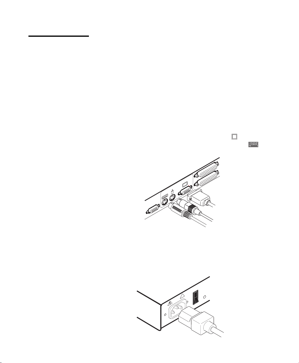
2. Connect your VGA monitor cable to the port labeled
this unit. Next, connect your keyboard to the port labeled
on the back of
on the
same unit.
A
USER
SETUP
E
3. Locate the power cord that came with your Paradigm unit. Plug it into
the IEC power connector on the Paradigm. Make sure that the Paradigm
power switch is off, then plug the other end of the power cord into an
appropriate AC wall outlet. This outlet must be near the equipment
and easily accessible to allow for unplugging prior to any servicing of
the unit.
1
!
0
28
, 50/60 Hz
100-240V , .1A
Page 35
Appendices
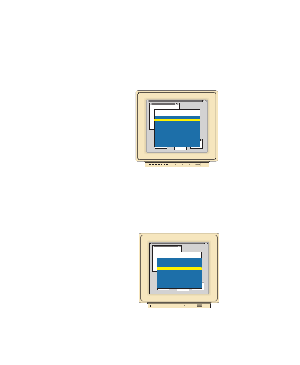
4. Turn the Paradigm unit on and press the
Control Control
Control key twice to activate
Control Control
the On-Screen Display system. The Administrator Channel list will
appear in a pop-up menu.
5. Press the
ControlControl
Control key twice more to activate the Administrator
ControlControl
Command Menu.
Program Manager
Rackit Control Panel
Administrator Command Menu
Channel Maintenance
Administrator Functions
Turn Scanning ON
Scanning Order
Sequential Scan Dwell Time
Reset Standard Mouse/Keyboard
Reset Wheel Mouse/Keyboard
Version Information
ENTER-accept ESC-previous
Games
6. Using the arrow keys, highlight ‘Administrator Functions’ and press
EnterEnter
Enter. This will bring up the Administrator Menu.
EnterEnter
7. From here, highlight and select ‘Unit Configuration’.
8. Change the unit configuration selection to option 3, ‘Paired (Slave)’.
Program Manager
Rackit Control Panel
Administrator Menu
Select Unit Configuration
1: Tiered (Default)
2: Paired (Master)
3: Paired (Slave)
Games
ENTER-accept ESC-previous
9. Press
Enter Enter
Enter to save your selection. Next, press the
Enter Enter
Esc Esc
Esc key repeatedly to
Esc Esc
exit from the OSD menu.
29
Page 36
Paradigm Installer/User Guide
10. Power down the slave Paradigm unit and disconnect the keyboard and
monitor.
11. Repeat Steps 2-7 with the remaining master Paradigm unit.
12. Now, choose option 2, ‘Paired (Master)’ for this unit. Press
save the selection and then press
Esc Esc
Esc repeatedly to exit the OSD menu.
Esc Esc
Enter Enter
Enter to
Enter Enter
13. Power down the master unit and disconnect the monitor.
Pairing Connections
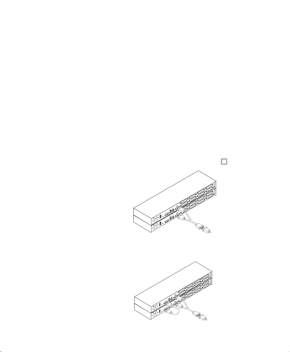
1. Locate the pairing cable kit. (CDUAL) It will contain a Y-video cable
with two 15-pin male VGA connectors and one 15-pin female VGA
connector. It also contains a 9 pin male serial cable.
2. Plug a male VGA connector into the port labeled
Paradigm units.
D
H
C
D
G
B
H
C
F
A
G
B
E
R
E
S
U
F
A
P
E
U
T
E
S
R
E
S
U
1
!
0
P
U
T
E
S
z
H
0
6
/
0
5
,
A
1
1
.
,
V
0
4
2
0
PATENT PENDING
0
!
1
0
z
H
0
6
/
0
5
,
A
1
.
,
V
0
4
2
0
PATENT PENDING
0
1
3. Connect the female VGA cable to the end of your monitor cable.
on each of the
MADE IN USA
MADE IN USA
4. Next, connect the serial cable between the ports labeled “SETUP” on the
Paradigm units.
MADE IN USA
D
H
C
MADE IN USA
D
G
B
H
C
F
A
G
B
E
R
E
S
U
F
A
E
SETUP
R
E
S
U
1
!
0
SETUP
1
PATENT PENDING
!
100-240V , .1A, 50/60 Hz
0
PATENT PENDING
100-240V , .1A, 50/60 Hz
5. Connect a PS/2 mouse to the master Paradigm unit.
30
Page 37
Appendices
Connecting Computers to the Paradigm
1. Power down the computers that will be part of your Paradigm system.
Make sure that both of your Paradigm units are turned off.
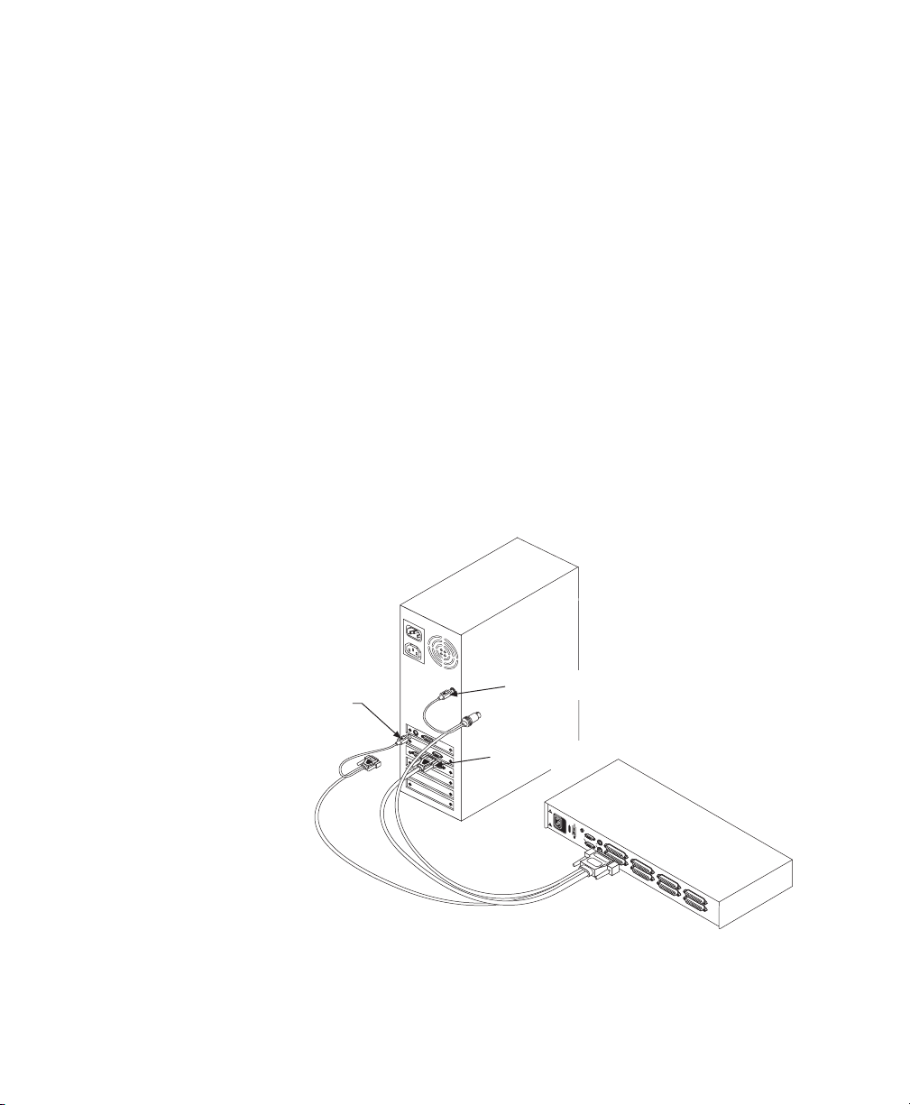
2. Locate your first computer interface cable. It will have a 25-pin “D”
connector at one end. Plug this cable into any lettered channel port on
the rear of the master Paradigm. The other end of the computer
interface cable will have five connectors: a 15-pin “HDD” connector
for your video, a 5-pin DIN/6-pin miniDIN connector for an AT or PS/
2 keyboard connection, and a 9-pin serial/6-pin miniDIN connector
for a serial or PS/2 mouse connection. The PS/2 mouse connector is
designated by a yellow band or mouse icon.
Use only the keyboard and mouse connectors that are appropriate forUse only the keyboard and mouse connectors that are appropriate for
Use only the keyboard and mouse connectors that are appropriate for
Use only the keyboard and mouse connectors that are appropriate forUse only the keyboard and mouse connectors that are appropriate for
your PC, and leave the others unconnected.your PC, and leave the others unconnected.
your PC, and leave the others unconnected.
your PC, and leave the others unconnected.your PC, and leave the others unconnected.
Plug these connectors into the appropriate ports on your computer.
MOUSE PORT
KEYBOARD PORT
VIDEO PORT
1
0
0
2
4
0
V
T
2
A
,
2
5
0
V
A
C
S
E
R
I
A
L
V
POWER
I
D
E
O
P
A
T
E
M
N
S
T
E
P
E
K
N
B
D
D
I
N
G
H
G
F
E
D
C
B
A
M
A
D
E
I
N
U
S
A
3. Locate your next computer interface cable. Repeat step 2 with all the
computers that will be attached to your master Paradigm. Next, attach
the remaining computers to the slave Paradigm.
31
Page 38
Paradigm Installer/User Guide
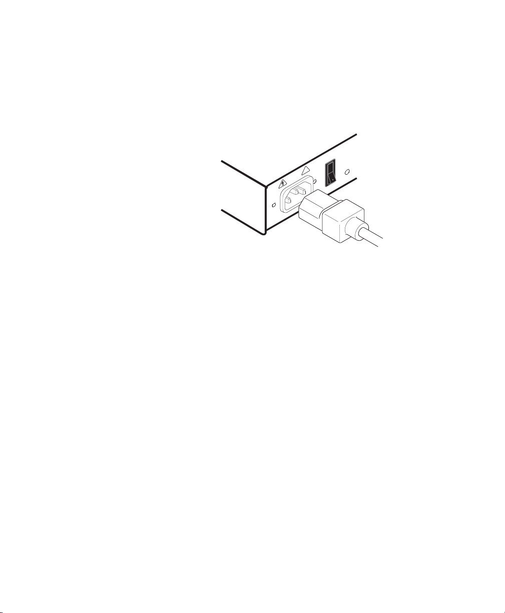
4. Locate the power cords that came with your Paradigm units. Plug each
one into the IEC power connectors on the Paradigm units. Make sure
that the power switches are off, then plug the other end of the power
cords into appropriate AC wall outlets. This outlet must be near the
equipment and easily accessible to allow for unplugging prior to any
servicing of the unit.
5. Power-up your slave Paradigm first followed by your master Paradigm,
then all attached computers.
The Paradigm and all attached computers should be powered down beforeThe Paradigm and all attached computers should be powered down before
The Paradigm and all attached computers should be powered down before
The Paradigm and all attached computers should be powered down beforeThe Paradigm and all attached computers should be powered down before
servicing the unit. Always disconnect the power cord from the wall outlet.servicing the unit. Always disconnect the power cord from the wall outlet.
servicing the unit. Always disconnect the power cord from the wall outlet.
servicing the unit. Always disconnect the power cord from the wall outlet.servicing the unit. Always disconnect the power cord from the wall outlet.
1
!
0
100-240V , .1A, 50/60 Hz
Adding New Channels with Paired Units
1. Select ‘Add Channel’ from the Channel Maintenance Menu. Type in a
new channel name, up to 14 characters long, and press
2. At the next prompt, type in the letter “A” if the PC is attached to the
master unit or “B” if it is attached to the slave unit. Press
3. When prompted for another cascade level, type Y and press
4. Type the letter that corresponds to the computer port that the computer
EE
is attached to on the Paradigm and press
nternter
E
nter.
EE
nternter
5. Type N when prompted for another cascade level and press
Esc Esc
Press
Esc at any point to exit this operation without adding a channel.
Esc Esc
Note: Keyboard switching is not available on paired units. All other
keyboard controls function as described earlier in the manual.
32
EnterEnter
Enter.
EnterEnter
EnterEnter
Enter.
EnterEnter
EnterEnter
Enter.
EnterEnter
EE
E
EE
nternter
nter.
nternter
Page 39

Uninstalling Pairing
Appendices
1. Press either
Control Control
Control key twice to bring up the On-Screen Display
Control Control
Administrator Channel List menu.
2. Press
3. Select ‘Unit Configuration’ and press
Control Control
Control twice again, select ‘Administrator Functions’ and press
Control Control
EnterEnter
Enter.
EnterEnter
EnterEnter
Enter.
EnterEnter
4. Change the unit configuration to ‘Option 1, Tiered’.
5. Press
Enter Enter
Enter to save your selection and
Enter Enter
EscEsc
Esc to exit OSD.
EscEsc
6. Disconnect the serial and video cables from both Paradigm units.
7. Attach a keyboard and monitor directly to the slave unit.
8. Repeat instructions 1-5 on the slave unit.
9. The units may now be cascaded together or used separately.
Note: Please note that the channel list will need to be modified according
to the Basic Channel Maintenance instructions in the manual after
uninstalling pairing.
33
Page 40

Paradigm Installer/User Guide
C: Troubleshooting
Our Technical Support staff is ready to assist you with any installation or
hardware problems you encounter with your Rackit product. If a problem
should develop, follow the steps below for the fastest possible service:
1. Check the troubleshooting tables below to see if the problem can be
resolved by following the procedures outlined.
2. If you are unable to find a resolution, recreate the problem when
possible. Fill out the Problem Report in Appendix D completely.
3. Call Rackit Technical Support between the hours of 9 a.m. and 5 p.m.
Eastern time, Monday through Friday at (212) 679-0050 for assistance.
Have your Problem Report with you when you call or fax it to Technical
Support at (212) 679-0040. To expedite assistance, have this manual
with you when you call, along with a copy of your invoice giving the
date purchased and other identifying data.
Symptom Action
No status light Verify unit is turned on. Check power cable. If status
light still does not light, turn off the unit and check the
fuse located under the power cord connector. If the
problem persists, contact Rackit Technical Support.
Red status LED lit Internal unit failure. Contact Rackit Technical Support.
Both amber and green If Scan button is depressed for longer than 3
Scan LEDs lit seconds, both LEDs will light momentarily and a reset is
sent to the unit. In order to initiate scanning, depress
the Scan button for 1-2 seconds only. If both LEDs
remain lit, call Rackit Technical Support.
Green channel LED not lit Verify that the computer is powered on. Check the
cabling between your computer and the Paradigm.
Verify that a keyboard works when plugged directly into
your PC. If the problem persists, contact Rackit
Technical Support.
34
Page 41

Appendices
Symptom Action
Unable to hot-key switch to Verify that no OSD menuing windows are up on your
a channel monitor. You must escape from all OSD menus to
enable hot-key switching.
Verify that you are not in secure mode. (No lock symbol
on OSD screen.)
Verify that you are in hot-key mode by checking to see
if the green status LED is blinking. If it is not, press
escape and try going into command mode again. If the
problem persists, contact Rackit Technical Support.
Unable to push-button switch Verify that the channel being selected is not serving as
to a channel an expansion unit.
Verify that you are not in secure mode. (No lock symbol
on OSD screen.)
Verify that a computer is attached to that channel. If
the problem persists, contact Rackit Technical Support.
No video Verify that the video cable between the PC and the
Paradigm is correctly connected. Verify that the monitor
cable is correctly connected to the Paradigm.
Power down the computer. Connect the monitor directly to
the computer and power up again. If the monitor operates
correctly direct to the computer, contact Rackit Technical
Support. If it does not, try another monitor.
Mouse jumps or “hugs” screen If the mouse has been hot-plugged while running in
Windows, you may need to close and restart Windows.
If the mouse still does not function, try the mouse
resynchronization command <ZM>. (For instructions on
command mode, see 'Basic Operations'.) If the problem
persists, contact Rackit Technical Support.
35
Page 42

Paradigm Installer/User Guide
Symptom Action
Mouse is inoperable on one If the mouse is inoperable on a channel, try the mouse
computer channel reset command <MR> or <MW> with that PC selected.
Mouse is inoperable on all Verify that the mouse is plugged into the correct PS/2
computer channel port on the back of the Paradigm.
(For instructions on command mode, see ‘Basic
Operations’.)
Verify that the cables from the computer to the
Paradigm are connected properly.
Make sure that you have keyboard/mouse privileges
for that channel.
Verify that the mouse driver and application are
configured properly for mouse support.
Verify that the computer works properly with a mouse
connected directly to it. If the problem persists, contact
Rackit Technical Support.
Verify that the mouse is PS/2 style and a supported
brand. (See the ‘Product Overview’ chapter for more
information.)
Try the mouse reset command <MR> or try the ‘Reset
standard mouse/keyboard’ command from the OSD
Command Menu for computers using PS/2 mice. Use
<MW> or ‘Reset wheel mouse’ for computers using the
Microsoft IntelliMouse. (For instructions on command
mode, see the ‘Basic Operations’ chapter.)
Verify that the mouse works when connected directly to
a computer.
Cycle power to the Paradigm unit. (You do not have
to power down your computers for this.) If the mouse
remains inoperable, power down all attached
computers, cycle power on the Paradigm, then
repower the computers. If the problem persists,
contact Rackit Technical Support.
36
Page 43

Appendices
Symptom Action
Keyboard is inoperable on If keyboard does not function on one channel, verify
one computer channel that the cables from the computer to the Paradigm
are connected properly.
If you are operating in secure mode, verify your
keyboard and mouse privileges.
Verify that the keyboard works properly connected
directly to the computer. If the problem persists, contact
Rackit Technical Support.
Keyboard is inoperable on If keyboard does not work on any channel, try the
all channels ‘Reset mouse/keyboard’ command from the OSD
Command Menu.
Try a different keyboard. If the keyboard still does not
function, cycle the power on the Paradigm unit.
Cycle power on all attached computers and the
Paradigm unit and try again. If the problem
persists, contact Rackit Technical Support.
Keyboard is inoperable after Try changing the keyboard scan set for that channel
switching channels by using the keyboard command sequence <Kn>. (For
more information, see the ‘Basic Operations’ chapter.)
If you are operating in secure mode, verify your keyboard
and mouse privileges. If the problem persists,
call Rackit Technical Support.
Characters on screen do not Try changing the keyboard scan set for that channel
match keyboard input by using the keyboard command sequence <Kn>. (For
more information, see the ‘Basic Operations’ chapter.) If
the problem persists, call Rackit Technical Support.
No keyboard, video or mouse Verify that the cable connecting the two units
on expansion unit; base unit together is correctly connected on both ends. (For
is functioning properly additional is information, see the ‘Installation’
chapter.) If the problem persists, contact Rackit
Technical Support.
37
Page 44

Paradigm Installer/User Guide
Symptom Action
OSD menu does not “pop-up” Verify that you are pressing the Control key twice
Unable to change channels Verify that the channel is powered. Check the
using OSD address configured in OSD. If the computer is
Administrator password is Call Technical Support.
forgotten
User password is forgotten Contact your system administrator.
General Keyboard/Video If the building has 3-phase AC power, ensure
Problems that the computer, the Paradigm and the monitor
within one second. If the problem persists, contact
Rackit Technical Support.
powered and the address is correct, call Rackit
Technical Support.
are on the same phase. Best results are
obtained when they are on the same circuit.
Use only Rackit supplied cable.
apply to damage resulting from user supplied cable.
Do not use a 2-wire extension cord in any
product configuration.
Test AC outlets at computer, Paradigm and monitor
for proper polarity and grounding.
Use only with grounded outlets at the computer,
Paradigm and monitor. When using a backup
power supply (UPS), power the computer, Paradigm
and the monitor off the supply.
System lockup during If there is no keyboard channel selection function,
paired operation try to bring up the OSD menu. If it activates,
reselect your channel and verify that the channel
functions normally. If the problem persists, contact
Technical Support.
If the OSD menu does not activate, verify that the
serial cable and video cables are securely attached
to both boxes. If not, reattach and try the OSD
menu again. If the problem persists, contact
Technical Support.
Rackit warranties do not
Rackit
38
Page 45

D: Problem Report
For the best possible service, please fill out this form completely. Have
your completed Problem Report with you when you call, or fax it to
Technical Support at (212) 679-0040.
Company Name:
Contact Name:
Phone Number: Fax Number:
Service Call Number (if one has been issued):
Paradigm Part #: Serial #: Revision:
Name and Model of Monitor:
Name and Model of Keyboard:
Name and Model of Mouse:
Appendices
Firmware Summary (results from <AV> command - see manual for
instructions on Command Mode):
Plus One =
N1= N2= N3= N4=
Version Information (Select from the OSD Command Menu):
List any non-PC equipment attached to the Paradigm. (Include other
Rackit products, additional peripherals, adaptors, etc.):
39
Page 46

Paradigm Installer/User Guide
Problem Description: (Include all affected ports, exact nature of problem,
troubleshooting steps taken, etc.)
Fill out the chart below, including every computer attached to your
Paradigm system.
Port
A
B
C
D
E
F
G
Computer
Manufacturer/
Model
BIOS
Manufacturer /
Revision
Operating
System
Graphics Card
Name/Model
Video
Resolution /
Scanrate
H
40
Page 47

Warranty
Rackit Technology Corporation warrants to the original retail purchaser that this
product is and will be free from defects in materials and workmanship for a period of
12 months from the date of purchase.
Additionally, Rackit Paradigm carries an unconditional 30 day satisfaction guarantee.
If, for any reason, you are dissatisfied with the performance of this product, you may
return it to the point of purchase for a refund of the purchase price (excluding
shipping charges). This guarantee does not apply to special order products, and may
not be available through all resellers. During the warranty period, purchaser must
promptly call Rackit for a Return Materials Authorization (RMA) number. Make sure
that the RMA number appears on the packing slip, proof of purchase, AND ON THE
OUTSIDE OF EACH SHIPPING CARTON. Unauthorized returns or collect shipments will
be refused.
Ship prepaid to:
274 Madison Avenue, Suite 1302
New York, NY 10016 • USA
212-679-0050 (Fax) 212-679-0040
The warranty is void under the following conditions:
1. If non-Rackit approved cabling is attached to the Paradigm. Poorly constructed and
miswired cabling can diminish video quality and damage equipment. Rackit manufactured cabling is built to high quality standards utilizing overall braided shield to
comply with FCC emission standards, and each cable is individually tested under
load.
2. If defect or malfunction was caused by abuse, mishandling, unauthorized repair, or
use other than intended.
3. If unauthorized modifications were made to product.
4. If unreported damages occurred in any shipment of the product.
5. If damages were due to/caused by equipment or software not provided by Rackit.
6. If the Paradigm is used with non-grounded or incorrectly polarized AC power.
EXCEPT AS SPECIFICALLY PROVIDED ABOVE, RACKIT MAKES NO WARRANTIES EITHER EXPRESS OR IMPLIED AS TO ANY MATTER WHATSOEVER, INCLUDING, WITHOUT
LIMITATION, THE CONDITION OF THE PRODUCT, ITS MERCHANTABILITY, OR ITS
FITNESS FOR ANY PARTICULAR PURPOSE. EXCEPT AS EXPRESSLY PROVIDED ABOVE,
RACKIT SHALL NOT BE LIABLE FOR LOSS OF PROFIT, LOSS OF BUSINESS, SPECIAL OR
CONSEQUENTIAL DAMAGES, OR OTHER FINANCIAL LOSS WHICH MAY BE CAUSED BY,
DIRECTLY OR INDIRECTLY, THE INADEQUACY OF THE PRODUCT FOR ANY PURPOSE
OR USE THEREOF OR BY ANY DEFECT OR DEFICIENCY THEREIN EVEN IF RACKIT OR AN
AUTHORIZED RACKIT DEALER HAS BEEN ADVISED OF THE POSSIBILITY OF SUCH
DAMAGES OR LOSSES.
Page 48

Paradigm Installer/User Guide
590-077-001 REV. B
 Loading...