

Page 1

VBOX Indoor Positioning System User Guide
• 01 - VBOX IPS Introduction
• 02 - VBOX IPS Hardware Installation
• 03 - VBOX IPS Rover Connection to VBOX 3i
• 04 - VBOX IPS Site Configuration
• 05 - VBOX IPS Using with a VBOX 3i/Standalone
• 06 - VBOX IPS Troubleshooting
• 07 - VBOX IPS Technical Properties
• VBOX IPS - PIN OUTS
• VBOX IPS - Technical Specification
• VBOX IPS - Upgrading Firmware
• VBOX IPS - Regulatory Information
1
Page 2

01 - VBOX IPS Introduction
Overview
VBOX Indoor Positioning System uses a network of fixed beacons in set locations that communicate with a receiver
mounted on the roof of a vehicle using Ultra Wideband (UWB), to measure position and speed where you cannot use
GNSS signals. A minimum of eight beacons are required and a site survey must be carried out as part of the installation,
to ensure the optimum accuracy. Doing so means the exact location of each beacon is known which can then be shared
with the rover enabling it to calculate its location to centimetre level accuracy.
The rover features an integrated VBOX IMU04 (Inertial Measurement Unit) for precise pitch, roll and yaw angular data. It
also connects directly to an IMU04 enabled VBOX 3i, enabling additional parameters from the vehicle’s CAN bus to be
logged. Offering seamless integration between indoor and outdoor environments, the system can be used for high
dynamic applications and the rover will automatically connect to the nearest beacons in range.
Features
• Can be used indoors and outdoors, switching
seamlessly between environments.
• Centimetre level accuracy in areas off limits to GPS
based systems.
• Small, rugged and low powered.
• Only one rover is required, featuring an integrated
VBOX IMU with Kalman filter to reduce noise and
errors in the data.
• Connects directly to a VBOX 3i data logger using
only one cable for simple configuration.
https://racelogic.support/01VBOX_Automotive/VBOX_Indoor_Positioning_System/VBOX_IPS_User_Guide/
• A minimum of 8 and maximum of 250 beacons can
be installed in each location allowing continuous
coverage of tracks up to 3.5 km long.
• Simple one time configuration either by Bluetooth or
serial cable (RS232).
• 100 Hz update and low latency for high dynamic
applications.
• The rover automatically connects to the nearest
beacons for optimum accuracy.
• Each beacon is numbered for simple installation.
2
Page 3
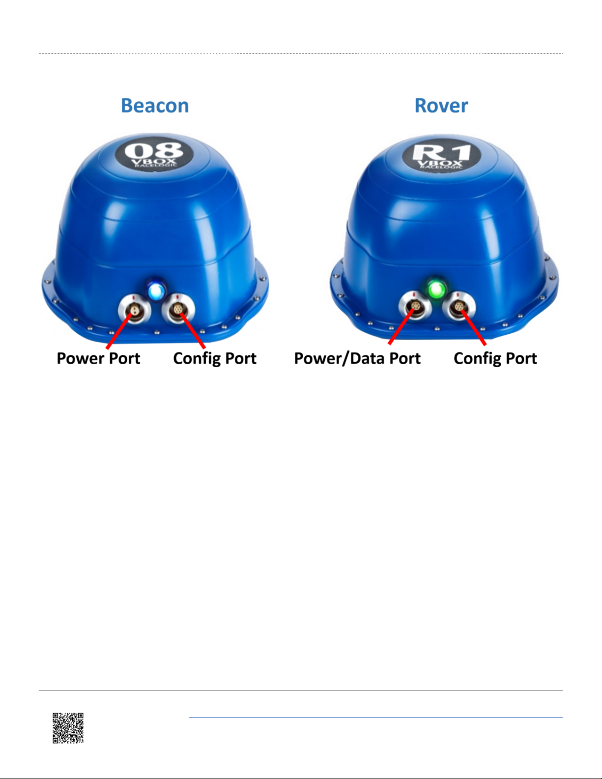
Connectors
https://racelogic.support/01VBOX_Automotive/VBOX_Indoor_Positioning_System/VBOX_IPS_User_Guide/
3
Page 4
02 - VBOX IPS Hardware Installation
Beacon (VIPS-B-V1) Installation
When first considering a VIPS installation or demonstration, it is important to understand the shape and size of the test
area and thus the minimum number of beacons that will be required.
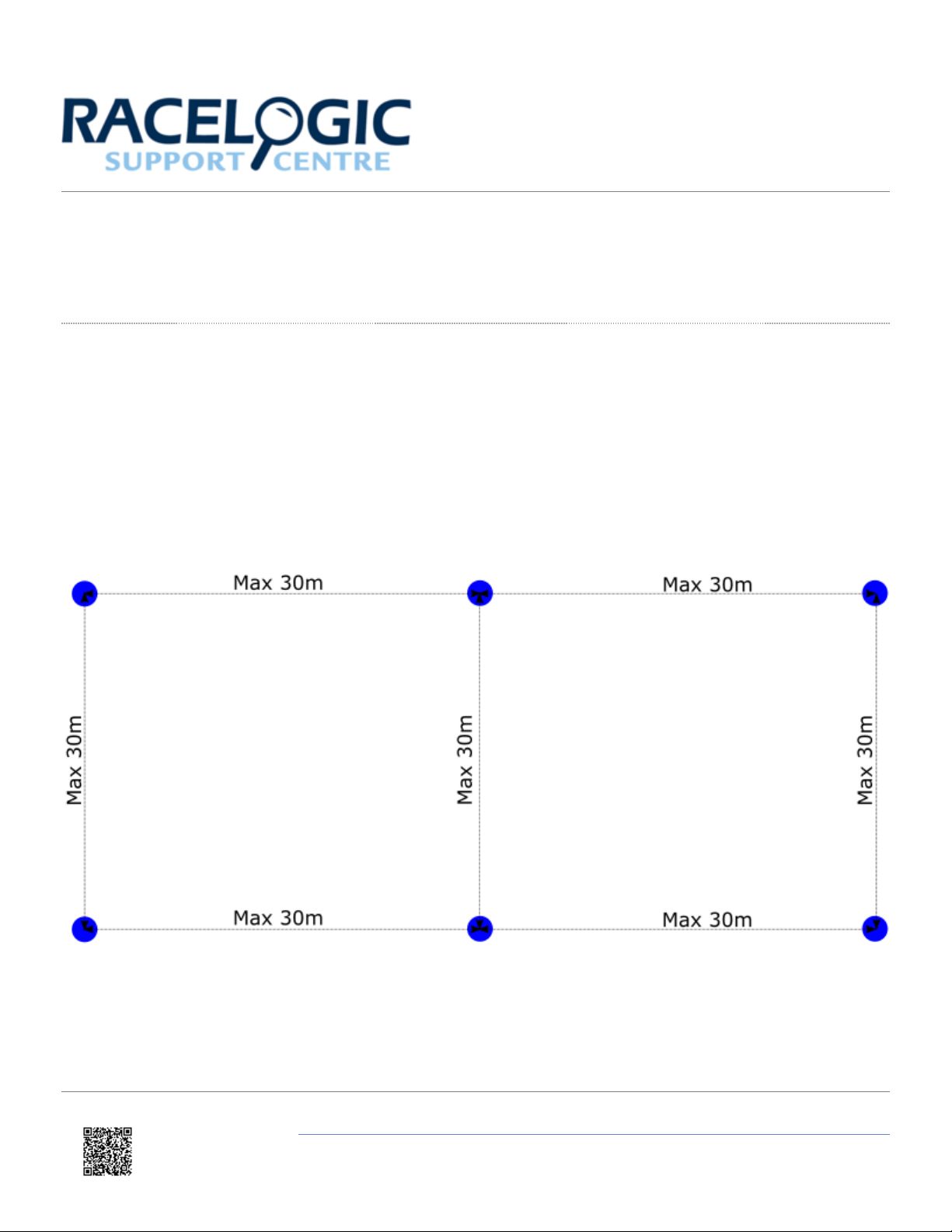
The VBOX IPS will need at least 6 beacons in view at any one time to compute a solution. For a simple installation,
Racelogic recommend placing the beacons in a ‘Square’ formation with spacing between the beacons of around 25–30
m, as below.
If operating in an outdoor/indoor mode, then the rover will not switch to use the VBOX IPS until 6 beacons are in view.
This means that it is only the first 6 beacons that will need to be placed closer together to ensure that 6 beacons are in
view before the vehicle enters the test area. The remaining beacons can be placed with a greater separation so long as
https://racelogic.support/01VBOX_Automotive/VBOX_Indoor_Positioning_System/VBOX_IPS_User_Guide/
4
Page 5
the vehicle is always within a 60 m radius of at least 6 beacons.
For greater accuracy, it is recommended that the beacons are placed between 3 – 5 m above ground (i.e. above the roof
of the test vehicle) and that each beacon varies in height by at least 300 mm to the nearest beacons, alternating in a
high-low pattern.
When mounting the VIPS beacons, there are a couple of considerations that need to be made. It is important when
mounting the beacons that they are not mounted within at least 200 mm (or greater if possible) of an object, other than
the surface the beacon is mounted to, that could cause reflections (e.g. a wall or metal structure) and that the beacons
are mounted in the correct orientation in relation to the expected orientation of the Rover when in use.
The beacons require a 9 – 36 V power source that is connected to the 2 way Lemo connector. The other Lemo
connector on the beacon is for Firmware upgrades and should be covered with the supplied splashproof plug to ensure
waterproofness.
The VIPS beacons have 4 magnets on the base allowing for easy installation onto any ferrous surface, however
Racelogic can supply metallic plates that can attach to a tripod for quick installations.
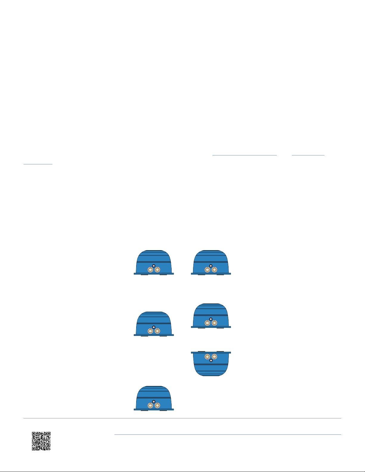
Suitable Beacon Orientations
✔
✔
✔
Side by side
Side by side with small height
difference
Side by side with large height
difference, tops towards each
other
https://racelogic.support/01VBOX_Automotive/VBOX_Indoor_Positioning_System/VBOX_IPS_User_Guide/
5
Page 6
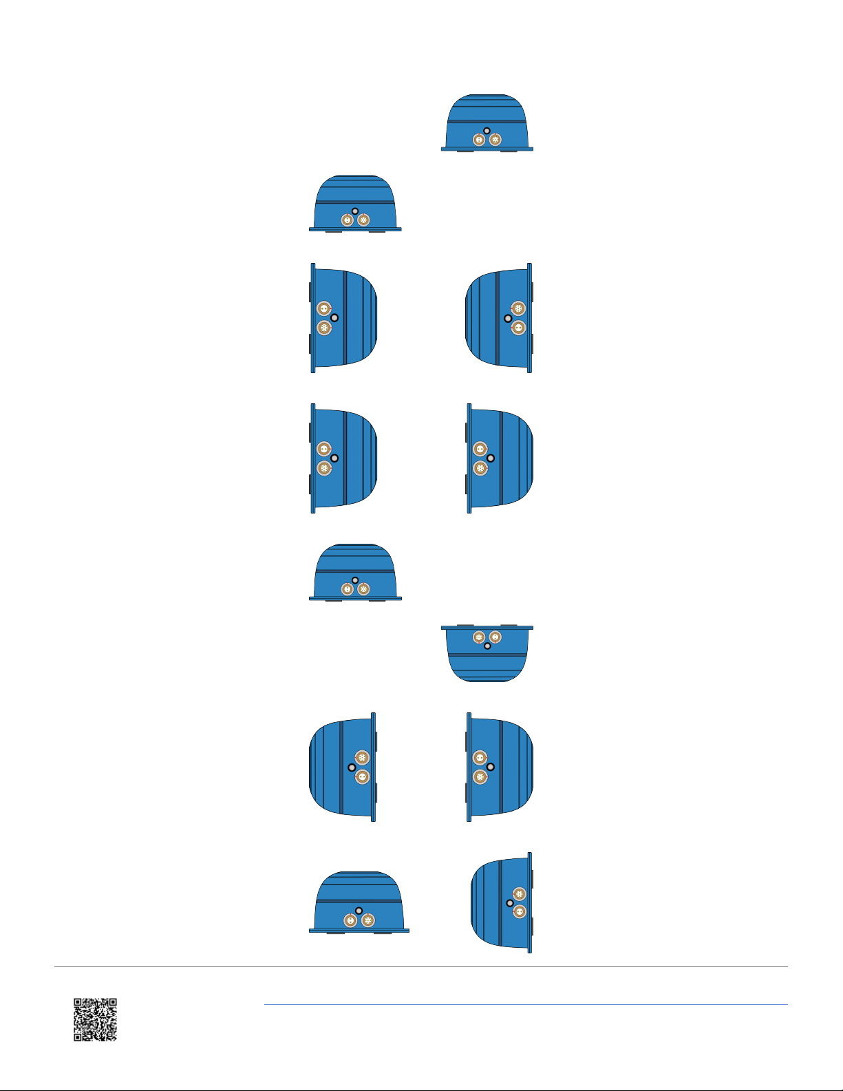
✗✗
✗✗
✗✗
Side by side with large height
difference
Tops together
Tops to base
✗✗
✗✗
✗✗
Base to base
Side to base
Side by side with large height
difference, tops away from each
other
https://racelogic.support/01VBOX_Automotive/VBOX_Indoor_Positioning_System/VBOX_IPS_User_Guide/
6
Page 7

Rover (VIPS-R-V2) Installation
The VIPS Rover looks similar to the Beacon, however the rover contains an internal IMU and so care should be taken to
ensure that the Rover is mounted on a section of the roof that has the least vibration. This is usually towards the rear of
the vehicle, just in front of the rear windshield. The rover should also be mounted in a way such that it has a clear view
to the beacons and away from any objects that may block that view (Roof bars, radio antennas etc).
https://racelogic.support/01VBOX_Automotive/VBOX_Indoor_Positioning_System/VBOX_IPS_User_Guide/
7
Page 8

03 - VBOX IPS Rover Connection to VBOX 3i
The Rover unit can connect to a standard VBOX 3i and switches seamlessly between GPS and the indoor positioning
system, allowing you to use your original hardware for both outdoor and indoor testing. As the VIPS is designed to be
used with IMU integration enabled, the same IMU Initialisation Process should be performed as normal.
For indoor only use, it is important that the VBOX 3i does not have a GPS antenna connected. If the VBOX receives a
satellite signal, even a poor one, the timing will change from the internal clock to GPS time, causing the VIPS system to
fail. the VBOX 3i will function the same as when using GPS in terms of CAN In / Out, data logging (analogue, etc.) and
VBOX Test Suite use.
When indoor/outdoor operation is selected, the VBOX IPS system will wait for GPS lock and IMU synchronisation before
attempting to initialise the VIPS positioning.
https://racelogic.support/01VBOX_Automotive/VBOX_Indoor_Positioning_System/VBOX_IPS_User_Guide/
8
Page 9
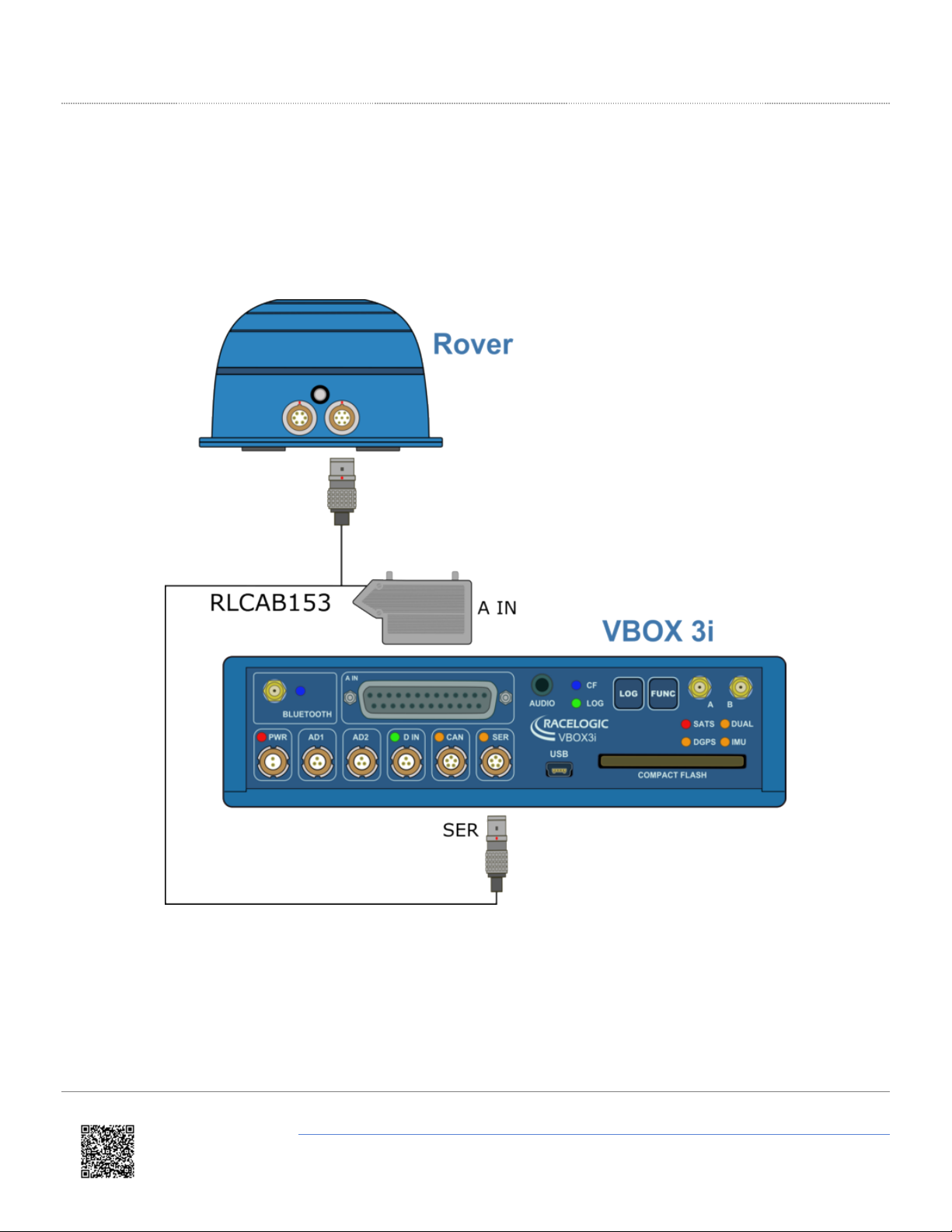
Using Internal IMU
Connection between the Rover and VBOX 3i is via the supplied RLCAB153 cable.
• Insert the 7 way Lemo connector in to the right hand connector on the Rover.
• Connect the 25 way connector to the A IN port on the VBOX 3i.
• Connect the 5 way Lemo connector to the SER port on the VBOX 3i.
https://racelogic.support/01VBOX_Automotive/VBOX_Indoor_Positioning_System/VBOX_IPS_User_Guide/
9
Page 10
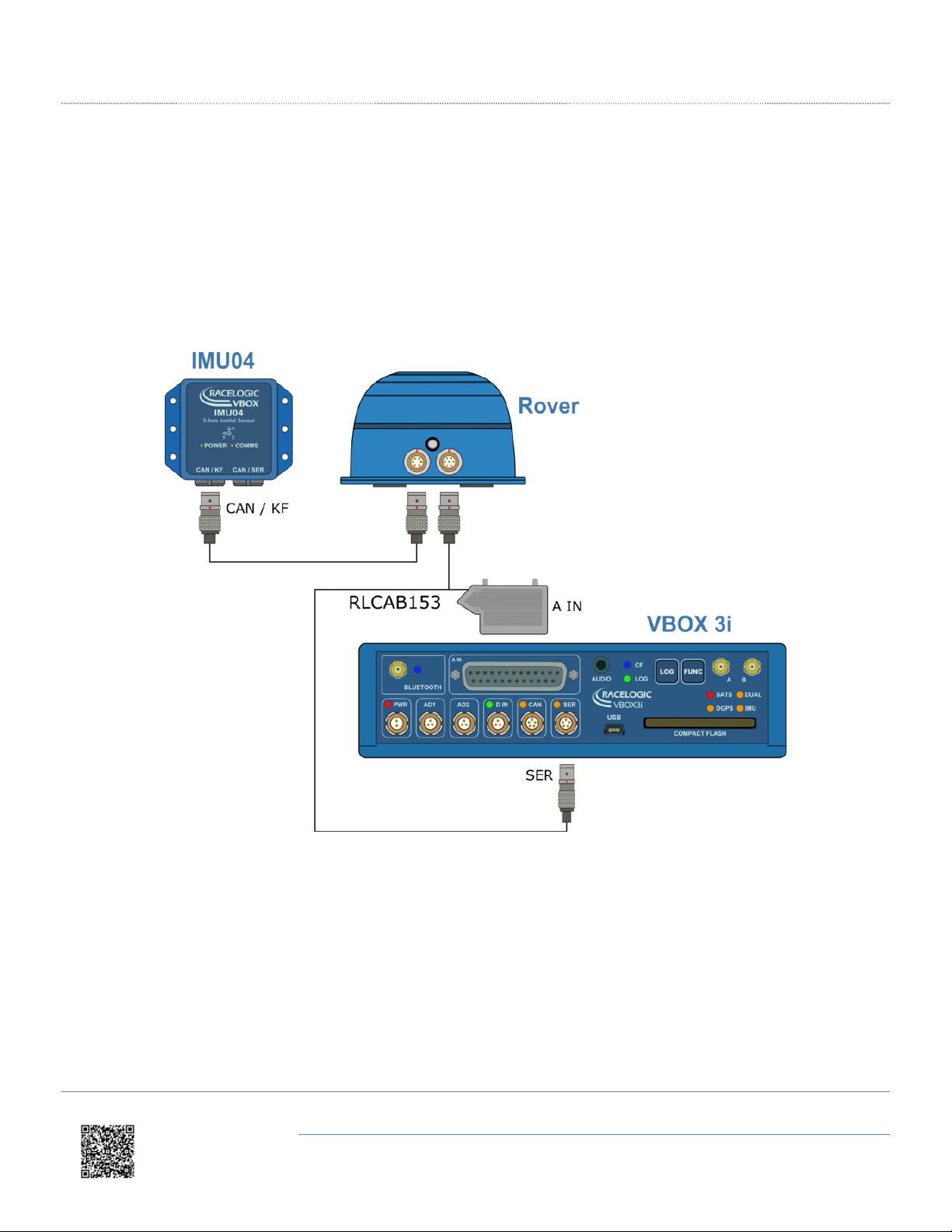
Using External IMU
Connection between the Rover and VBOX 3i is via the supplied RLCAB153 cable.
• Insert the 7 way Lemo connector in to the right hand connector on the Rover.
• Connect the 25 way connector to the A IN port on the VBOX 3i.
• Connect the 5 way Lemo connector to the SER port on the VBOX 3i.
• Insert the 6 way Lemo connector in to the left hand connector on the Rover.
• Insert the other end of the cable in to the CAN / KF port on the IMU04.
https://racelogic.support/01VBOX_Automotive/VBOX_Indoor_Positioning_System/VBOX_IPS_User_Guide/
10
Page 11
04 - VBOX IPS Site Configuration
For the VBOX IPS to work correctly, the rover needs to know the expected site configuration. This configuration informs
the rover of the expected Beacon IDs it will be using and their locations. This information needs to be manually entered
by the user using the VIPS Site Configuration Software.
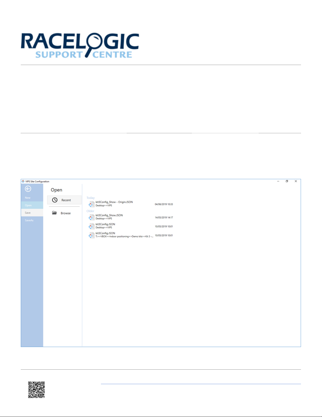
Getting Started
On opening, the user is presented with the option to load a previously saved site configuration (.JSON file) or create a
new configuration. On this screen, you can also choose to save the current settings.
https://racelogic.support/01VBOX_Automotive/VBOX_Indoor_Positioning_System/VBOX_IPS_User_Guide/
11
Page 12

By selecting New, or a previously saved configuration file, you are then presented with options necessary for correct
VIPS operation.
Site Settings
The first page the user is presented with is the Site Settings tab. Here you can configure how the Rover is expected to
operate and also change the Radio Settings.
Note: The radio settings are for Racelogic development purposes only.
Identifier
There may be multiple VBOX IPS operating within the same test ground and so to ensure the rover only uses the
signals coming from the intended test site, a site identifier needs to be entered. This identifier will need to match the site
identifier of the beacons that will be used.
For temporary installations, this identifier should be set to 0. For permanent installations a non-zero number should be
used.
https://racelogic.support/01VBOX_Automotive/VBOX_Indoor_Positioning_System/VBOX_IPS_User_Guide/
12
Page 13

Origin
For indoor/outdoor use, it is important that the origin of the VBOX IPS matches a global coordinate system to ensure
there is a smooth transition between GPS and VBOX IPS position.
The enter value of the origin should be a georeferenced location that is the 0,0 point from which all VBOX IPS beacon
measurements are taken from.
Rotation Angle
As well as a georeferenced origin, it is also important that the VBOX IPS x/y measurements are rotated correctly into a
‘North up’ frame.
The entered value in the rotation angle should be the bearing of the track direction, in degrees from North.
For indoor use only, the rotation angle should be set to 0.
Indoor or Indoor/Outdoor
Choose whether the expected use will be indoors only, or indoors and outdoors.
VB3i or Stand alone
Although VBOX IPS can be connected to a VB3i, there is also the option to use the system without a VBOX, called
‘stand alone’.
When in stand alone mode, the VBOX IPS will generate a 100 Hz PPS output that other equipment may use for
synchronisation. When in VB3i mode, this pin becomes an input and should be connected to the PPS from the VBOX.
Beacons
Each VBOX IPS installation will contain a number of beacons. In this section of the software, it is possible to set the
Beacon IDs that will be used as well as the x,y,z distances to the origin.
https://racelogic.support/01VBOX_Automotive/VBOX_Indoor_Positioning_System/VBOX_IPS_User_Guide/
13
Page 14

Load
The Load Button allows you to load the settings from previously surveyed installation.
Add
The Add Button allows you to add a new beacon into the system. Adding a new beacon will automatically increment the
‘Friendly ID’ by 1.
Delete
The Delete Button allows you to remove the selected beacon from the installation.
Note: There will be no negative effects of having beacons in the configuration that will not actually be present in the
physical installation.
Clear all
The Clear all button will remove all beacons in the list.
Friendly ID
The Friendly ID is a user friendly ID that should match the sticker on the Beacon. The Friendly ID cannot be changed
and will be a consecutive count up from 1.
https://racelogic.support/01VBOX_Automotive/VBOX_Indoor_Positioning_System/VBOX_IPS_User_Guide/
14
Page 15

Beacon ID
The Beacon ID is a unique identifier that is hard coded into the beacon, similar to a serial number. This ID number can
be changed to match the Friendly ID as needed, allowing for replacement beacons to be easily swapped in and out.
Offset
The Offset is the distance between the beacon and the nominated origin location, with East, North and Up being
positive values, West, South and Down being negative values (assuming a rotation angle of 0).
Delay
The Delay option allows for further calibration to the beacons if needed.
Status
The Status display gives a live display of whether the beacon is currently operating or not.
Ping Table
The VBOX IPS rover needs to know the expected order it will receive the ‘Ping’ signals from the beacons, based on
whichever beacon is nearest. Once the Beacon Offsets have been entered, you should press the Calculate button to
update the Ping Table. For sites with unusual layouts it may be necessary to manually edit this table, but for most sites
the automatic calculation will be correct.
It is important that the Ping table correctly matches the expected number of beacons, with the addition of ‘Beacon 0’
which is always present.
https://racelogic.support/01VBOX_Automotive/VBOX_Indoor_Positioning_System/VBOX_IPS_User_Guide/
15
Page 16

Upload to Beacon
Once the site configuration has been entered correctly, the information is needed to be uploaded to the Rover. This can
be done via Bluetooth, however for the initial release it is recommended to use the supplied configuration cable.
To upload the configuration, a COM port will first need to be selected from the drop down list of available COM ports. If
the required COM port is not displayed, pressing the Refresh button will refresh the COM port list.
https://racelogic.support/01VBOX_Automotive/VBOX_Indoor_Positioning_System/VBOX_IPS_User_Guide/
16
Page 17

When uploading to a Rover once a COM port is selected, the user will need to Enter LPC mode. This is only required
once per power cycle. Once in ‘LPC Mode’ the user can then press the Upload button to upload the configuration to the
beacon. The software will then inform the user whether the upload has been successful or not.
When uploading to a Beacon there is no need to first enter LPC mode, the configuration can be uploaded directly.
https://racelogic.support/01VBOX_Automotive/VBOX_Indoor_Positioning_System/VBOX_IPS_User_Guide/
17
Page 18

05 - VBOX IPS Using with a VBOX 3i/Standalone
Using VBOX IPS with a VBOX 3i
When set to VB3i connected within the VIPS Site Configuration Software and the correct Site Configuration
uploaded to the Rover unit, it is now possible to start testing using a VB3i and VBOX IPS. The VBOX 3i will function the
same as when using GPS in terms of CAN In/Out, data logging (analogue, etc.) and VBOX Test Suite use.
As the VIPS is designed to be used with IMU integration enabled, the same IMU Initialisation Process should be
performed as normal. When indoor/outdoor operation is selected, the VBOX IPS system will wait for GPS lock and IMU
synchronisation before attempting to initialise the VBOX IPS positioning.
Using VBOX IPS as Stand Alone
When set to Stand alone within the VIPS Site Configuration Software and the correct Site Configuration uploaded to
the Rover unit, the VBOX IPS can be used without a VBOX by connecting the Rover unit via serial connection. In this
mode, there is no Kalman filtering of the data, making the output data more noisy than the VBOX solution.
Site ID
When a rover powers up it searches for beacons. Once 1 or more beacons are found, it queries the closest beacon for
its site ID and the checksum for its configuration information.
This site ID and checksum are then compared to the last 4 sites that the Rover has seen. If they match, the Rover will
load the configuration from memory and start running.
If the ID and/or checksum don’t match anything the Rover has seen before, it will then initiate a Bluetooth connection to
the beacon and download the site configuration information. This means that only the beacons need to be configured,
any rover can arrive at the site and will automatically work without further configuration.
https://racelogic.support/01VBOX_Automotive/VBOX_Indoor_Positioning_System/VBOX_IPS_User_Guide/
18
Page 19

Site Origin of 0
VBOX IPS normally outputs locations in degrees latitude and longitude, if however an origin of 0,0 is given, then the
conversion to latitude/longitude is skipped and the VBOX IPS rover will output in meters X,Y. When operating with a
VB3i, an origin is always needed, when operating in standalone mode, this is optional.
https://racelogic.support/01VBOX_Automotive/VBOX_Indoor_Positioning_System/VBOX_IPS_User_Guide/
19
Page 20

06 - VBOX IPS Troubleshooting
Upload Timeout
When uploading the VBOX IPS configuration, the process may time out. If this occurs, there are a number of things that
can be changed to solve the issue, other than repeated attempts.
1. The first is to increase the Timeout number within the VIPS Site Configuration Software. Increasing this number
will increase the amount of time that passes before communication times out.
2. The second option is to ensure that the USB transfer Sizes are set to the maximum of 4096 on both receive and
transmit. This is configured under the Advanced options of the Port Settings.
https://racelogic.support/01VBOX_Automotive/VBOX_Indoor_Positioning_System/VBOX_IPS_User_Guide/
20
Page 21

07 - VBOX IPS Technical Properties
VBOX IPS - PIN OUTS
Connector pin information
VBOX IPS - Upgrading Firmware
How to update the VPRS beacon and rover
Firmware. Occasionally Racelogic will release
new versions of firmware (internal code) for the
VPRS units, often to introduce new features
VBOX IPS - Technical
Specification
Beacon/rover specification and size information
VBOX IPS - Regulatory
Information
USA, Canada and Radiation Exposure regulatory
information
https://racelogic.support/01VBOX_Automotive/VBOX_Indoor_Positioning_System/VBOX_IPS_User_Guide/
21
Page 22

VBOX IPS - PIN OUTS
Beacon
Beacon front view
https://racelogic.support/01VBOX_Automotive/VBOX_Indoor_Positioning_System/VBOX_IPS_User_Guide/
22
Page 23

Connector 1 - POWER (Lemo 2 PIN)
PIN I/O Function
1 I +12 V Power
2 I Ground
Connector 2 (Lemo 7 PIN)
PIN I/O Function
1 N/A N/C
2 N/A N/C
3 O VIPS Tx
4 I VIPS Rx
5 N/A N/C
https://racelogic.support/01VBOX_Automotive/VBOX_Indoor_Positioning_System/VBOX_IPS_User_Guide/
23
Page 24

PIN I/O Function
6 I +12 V Power
7 I Ground
Chassis I Shield
Rover
Connector 1 (Lemo 6 PIN)
Rover front view
https://racelogic.support/01VBOX_Automotive/VBOX_Indoor_Positioning_System/VBOX_IPS_User_Guide/
24
Page 25

PIN I/O Function
1 N/A Do not use
2 N/A Do not use
3 I/O CAN High
4 I/O CAN Low
5 I +12 V Power
6 I/O PPS
Chassis I Ground
Connector 2 (Lemo 7 PIN)
PIN I/O Function
1 I IMU Rx
2 O IMU Tx
3 O VIPS Tx
4 I VIPS Rx
5 I/O PPS
6 I +12 V Power
7 I Ground
https://racelogic.support/01VBOX_Automotive/VBOX_Indoor_Positioning_System/VBOX_IPS_User_Guide/
25
Page 26

PIN I/O Function
Chassis I Shield
https://racelogic.support/01VBOX_Automotive/VBOX_Indoor_Positioning_System/VBOX_IPS_User_Guide/
26
Page 27

VBOX IPS - Technical Specification
Rover Specifications
Velocity
Accuracy 0.1 km/h (averaged over 4 samples)
Update rate 100 Hz
Maximum velocity 300 km/h
Minimum velocity 0.1 km/h
Resolution 0.1 km/h
Latency 60 ms
Relative Positioning
Horizontal accuracy <10 cm (95 % CEP*)
Update rate 100 Hz
Height accuracy 1 m (95% CEP*)
Absolute position <10 cm (95% CEP*)^
https://racelogic.support/01VBOX_Automotive/VBOX_Indoor_Positioning_System/VBOX_IPS_User_Guide/
27
Page 28

Distance
Accuracy 0.05% (<50 cm per km)
Update rate 100 Hz
Resolution 1 cm
Acceleration
Accuracy 0.5 %
Maximum 20 g
Resolution 0.01 g
Update rate 100 Hz
Heading
Resolution 0.01°
Update rate 100 Hz
Time
Resolution 0.01 s
Accuracy 30 ns
https://racelogic.support/01VBOX_Automotive/VBOX_Indoor_Positioning_System/VBOX_IPS_User_Guide/
28
Page 29

Brake Stop Accuracy (Trigger activated)
Accuracy 5 cm**
Definitions
* Circle of Error Probable (CEP): 95 % of the time the position readings will fall within a circle of the stated diameter
** Based on <50 m brake stop distance
^ Subject to accurate site survey and installation
UWB Radio
Frequency 4.0 – 5.0 GHz or 6.0 – 7.0 GHz
Transmit power (peak / average) 0 dBm / -41.3 dBm
Outputs
Rover
RS232 Output
RS232 Port 1 Position and velocity
RS232 Port 2 IMU04 data
Output data rate 100 Hz
https://racelogic.support/01VBOX_Automotive/VBOX_Indoor_Positioning_System/VBOX_IPS_User_Guide/
29
Page 30

Digital Output
Signal levels 5 V DC
Output type 1 PPS*
Beacon
RS232 Output
RS232 Port 1 Configuration only
Inputs
Rover
Unit Power
Input voltage range 6.5 – 30 V DC
Power consumption 2 W
Digital Input
Input Function 1 PPS*
https://racelogic.support/01VBOX_Automotive/VBOX_Indoor_Positioning_System/VBOX_IPS_User_Guide/
30
Page 31

Beacon
Unit Power
Input voltage range 6.5 – 30 V DC
Power consumption 2 W
Rover IMU Specifications
Gyroscopes (Angular rate
sensors)
Dynamic range ±450°/s ± 20 g
Nonlinearity 0.01 % of full scale 0.1 % of full scale
Resolution 16-bit ADC (0.014°/s) 16-bit ADC (0.15 mg)
Bandwidth 50 Hz 50 Hz
Noise density 0.01°/s/√Hz 60 µg/√Hz
Bias stability 0.003°/s 15 µg
Bias repeatability (1 year) 0.2°/s 0.005 g
Accelerometers
Environmental and Physical
IP rating IP 67
Operating temperature -30°C to +60°C
Storage temperature -40°C to +85°C
Size (of each beacon/rover) 124 x 124 x 74.5 mm (l x w x h)
Weight (of each beacon/rover) 350 g
https://racelogic.support/01VBOX_Automotive/VBOX_Indoor_Positioning_System/VBOX_IPS_User_Guide/
31
Page 32

Beacon/Rover Dimensions
Measured in mm.
https://racelogic.support/01VBOX_Automotive/VBOX_Indoor_Positioning_System/VBOX_IPS_User_Guide/
32
Page 33

VBOX IPS - Upgrading Firmware
Firmware refers to the operating software inside the beacons and rover. Firmware is already installed within the VIPS
units when purchased, however as more features are added in the future, the units may require updating from time to
time.
The latest firmware will always be available in the firmware section of the VBOX Automotive website.
To upgrade the VIPS firmware:
1. Download the Latest VIPS Beacon and VIPS Rover Firmware Files from the VBOX Automotive website and
copy these files onto your computer.
2. Download the Racelogic Upgrader Software from the software section of the VBOX Automotive website.
Note: Pease ensure that the latest version of Racelogic Upgrader is installed.
3. Connect the RLCAB151-L serial configuration cable, from the PC direct to the Configuration Port of the VIPS
unit.
4. Connect the unit to power using the 2 pin power Lemo connector on the configuration cable.
5. Either ‘double click’ on the ‘.upgrade’ firmware upgrade file, which auto runs the Upgrader software, or run
the Upgrader software and load in the ‘.upgrade’ firmware upgrade file.
6. Ensure the correct COM port is selected within 'Options' and press ‘Upgrade' to start the process.
7. Follow the onscreen instructions and the module firmware will be upgraded. At the end of the process, power down
the module when prompted before further use.
https://racelogic.support/01VBOX_Automotive/VBOX_Indoor_Positioning_System/VBOX_IPS_User_Guide/
33
Page 34

VBOX IPS - Regulatory Information
For customers in the United States
This device complies with Part 15 of the FCC Rules:
Operation is subject to the following conditions:
1. This device may not cause harmful interference, and
2. This device must accept any interference received, Including interference that may cause undesired operation.
Changes and Modifications not expressly approved by RACELOGIC can void your authority to operate this equipment
under Federal Communications Commissions rules.
For customers in Canada
This device complies with Industry Canada licence-exempt RSS standard(s). Operation is subject to the following two
conditions: (1) this device may not cause interference, and (2) this device must accept any interference, including
interference that may cause undesired operation of the device.
Le présent appareil est conforme aux CNR d'Industrie Canada applicables aux appareils radio exempts de licence.
L'exploitation est autorisée aux deux conditions suivantes : (1) l'appareil ne doit pas produire de brouillage, et (2)
l'utilisateur de l'appareil doit accepter tout brouillage radioélectrique subi, même si le brouillage est susceptible d'en
compromettre le fonctionnement.
https://racelogic.support/01VBOX_Automotive/VBOX_Indoor_Positioning_System/VBOX_IPS_User_Guide/
34
Page 35

Radiation Exposure Statement
The device has been found to be compliant to the requirements set forth in CFR 47 Sections 2.1091 and Industry
Canada RSS-102 for an uncontrolled environment. The antenna(s) used for this transmitter must be installed to provide
a separation distance of at least 20 cm from all persons and must not be co-located or operating in conjunction with any
other antenna or transmitter.
Le dispositif a été jugé conforme aux exigences énoncées dans les articles 47 CFR 2.1091 et Industrie Canada
RSS-102 pour un environnement non contrôle’. L’antenne(s) utilisée pour ce transmetteur doit etre installé pour fournir
une distance de séparation d’au moins 20 cm de toutes les personnes et ne doit pas être co-localisés ou fonctionner en
conjunction avec une autre antenne ou transmetteur.
https://racelogic.support/01VBOX_Automotive/VBOX_Indoor_Positioning_System/VBOX_IPS_User_Guide/
35
 Loading...