

Page 1
INSTALLATION
& USER GUIDE
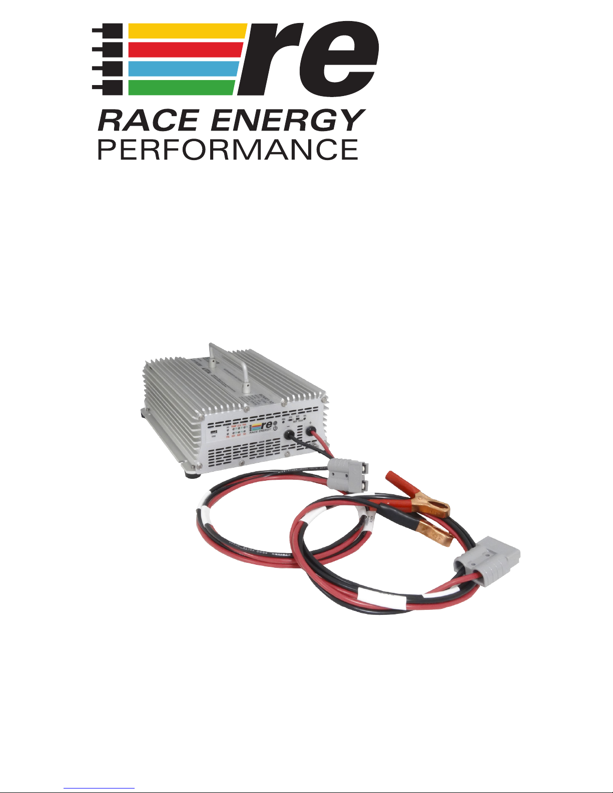
BCM21
Motorsports
Intelligent Battery Charger
8128 River Way, Delta B.C. V4G 1K5 Canada
T. 604.946.9981 F. 604.946.9983 TF. 800.668.3884 (US/CANADA)
www.RaceEnergyPerformance.com
Page 2

Copyright ©2015 Race Energy Solutions Ltd.
Page 3

3
SAVE THESE INSTRUCTIONS — This user guide contains important safety and
operating instructions for the battery charger.
BATTERY CHARGER PRECAUTIONS
1. Do not expose the battery charger to rain or snow unless it is a sealed model.
2. Use of an attachment not recommended or sold by the battery charger
manufacturer may result in a risk of re, electric shock, or injury to persons.
3. Do not disassemble the battery charger; return it to the manufacturer or
an authorized service center when service or repair is required. Incorrect
reassembly may result in a risk of electric shock or re. Voltages in excess of
350 volts are present inside the charger anytime it is plugged into an AC outlet,
even if it is switched off.
4. To reduce risk of electric shock, unplug the battery charger from the AC outlet
before attempting any maintenance or cleaning. Turning off controls will not
reduce this risk.
5. Never place battery charger directly above battery; gases from battery will
corrode and damage battery charger.
6. Never allow battery acid to drip on the battery charger.
BATTERY SAFETY
1. WARNING — RISK OF EXPLOSIVE GASES.
i. WORKING IN VICINITY OF A LEAD-ACID BATTERY IS DANGEROUS.
BATTERIES GENERATE EXPLOSIVE GASES DURING NORMAL BATTERY
OPERATION. FOR THIS REASON, IT IS OF UTMOST IMPORTANCE THAT
EACH TIME BEFORE SERVICING EQUIPMENT IN THE VICINITY OF THE
BATTERY, YOU READ THIS USER GUIDE AND FOLLOW THE INSTRUCTIONS
EXACTLY.
ii. To reduce risk of battery explosion, follow these instructions and those
published by battery manufacturer and manufacturer of any equipment you
intend to use in vicinity of battery. Review cautionary marking on these
products and on engine.
2. PERSONAL PRECAUTIONS
i. Someone should be within range of your voice or close enough to come to
your aid when you work near a battery.
ii. Have plenty of fresh water and soap nearby in case battery acid contacts
skin, clothing, or eyes.
iii. Wear complete eye protection and clothing protection. Avoid touching eyes
while working near battery.
SAFETY AND OTHER
IMPORTANT INSTRUCTIONS
Page 4

4
iv. If battery acid contacts skin or clothing, wash immediately with soap and
water.
v. If acid enters eye, immediately ood eye with running cold water for at
least 10 minutes and get medical attention immediately.
vi. NEVER smoke or allow a spark or ame in the vicinity of a battery or
engine.
vii. Be extra cautious to reduce risk of dropping a metal tool onto battery. It
might spark or short-circuit the battery or other electrical part that may
cause a re or explosion.
viii. Remove personal metal items such as rings, bracelets, necklaces, and
watches when working with a lead-acid battery. A lead-acid battery can
produce a short- circuit current high enough to melt metal, causing a
severe burn.
ix. NEVER charge a frozen battery.
x. If it is necessary to remove a battery from service, always remove
grounded terminal from battery rst. Make sure all accessories connected
to the battery are off, so as not to cause an arc when reconnecting the
new battery.
xi. Be sure area around battery is well ventilated.
xii. Clean the battery terminals. Be careful to keep corrosion from coming in
contact with eyes.
xiii. Study all the battery manufacturer’s specic precautions such as removing
or not removing cell caps while charging and recommended rates of
charge.
DANGER: Never alter the AC cord of plug provided - if it
will not t outlet, have proper cord installed by a qualied
electrician. Improper connection can result in a risk of an
electric shock.
The plug must be plugged into an outlet that is properly installed and grounded in
accordance with all local codes and ordinances.
GROUNDING AND AC POWER CORD
CONNECTION INSTRUCTIONS
Page 5

5
SPECIFICATIONS
Input
Volts 85 - 265 VAC, 1 Phase, 45 - 65 Hz
Current (max) * 4 Amps w. Inrush Protection
Input Fuse AGC 5 Amp
Power Factor > 0.99 at Full load
Efciency >90% at Full Load
* Maximum Input Current Specied at 85 VAC
Output
Nominal Voltage 12 VDC
Voltage Range ** 12.0 - 15.5 VDC
Output Current 20 Amps
Recommended Battery Amp-Hours 20 - 100
Charging Stages 2 or 3 stage user selectable
End of Charge Float or Rest user selectable
**Actual Output Voltage determined by User Settings or by Charger Firmware
Mechanical
Dimensions 9.5"/24.1cm Long x 8.0"/20.3cm Wide x 3.75"/9.5cm High
Weight 6.2 lb / 2.8 kg
Material and Finish Marine Grade Clear Anodized Aluminum with 18-8 Stainless Fasteners
Mounting Free Standing with protective feet and carrying handle.
Connections 1 meter cable c/w 50 Amp Anderson style plug-in connector, plus a
matching cable with solid copper alligator clips.
Environmental and Safety
Operating Temperature Range -25 to +40 C (-40 to +55 C Optional)
Storage Temperature Range -55 to +85 C
Humidity 0 - 95% Relative Humidity (non-condensing)
Vibration Built to meet MIL810g
Emissions Complies with FCC Class B, Part 15
Isolation > 1500 VDC Input-Output, Input-Case, Output-Case
Audible Noise None
Duty Cycle Continuous
Warranty Five Years Parts and Labor
Safety Built to meet ABS, CE, UL458 and CSA 22.2.107.1
Designed and manufactured by: RACE ENERGY PERFORMANCE
8128 River Way
Delta, BC V4G 1K5 Canada
p. 604.343.4577 f. 604.946.9983
tf. 800.668.3884 US/Canada
www.raceenergyperformance.com [email protected]
Page 6

6
INTRODUCTION
The BCM21 Intelligent Motorsports Battery Charger delivers a full 20 amps of
charging power to a 12 volt battery in a race car or other vehicle.. The charger
comes standard with a 50 Amp Anderson SB-50 plug-in connector for connecting
to the race car and a matching cable with alligator clips for other batteries.
The charger uses advanced Power Factor Correction circuitry on the AC input. This
means that it will work from any standard AC voltage anywhere in the world and
uses the electricity in the most effective and efcient way. Power Factor Correction
is a way of drawing AC power from the grid in exactly the same way as an
incandescent light bulb (i.e. the current drawn is exactly proportional to the voltage
at every point in the standard 50 or 60 Hz cycle). This will eliminate any additional
charges on your electric bill for ‘Phantom’ or ‘Apparent’ power by the charger or
minimize the load on a generator.
The charger uses Zero Voltage/Zero Current switching on the Primary or high
voltage side of the main power transformer, and Active Rectication on the
Secondary or Low Voltage side of the main power transformer for maximum
efciency and lowest Electromagnetic Interference (EMI) to ensure that it does not
interfere with sensitive voice or data RF communication equipment.
The charger can be pre-set on one of three default battery temperatures, or it can
be programmed to automatically estimate the battery temperature by reading its
own temperature at the time it is turned on. It will automatically adjust its charging
voltage to the correct value for that temperature.
The charger is preprogrammed for three standard types of Lead Acid batteries;
Flooded (traditional Lead Acid), AGM (Absorbed Glass Mat Lead Acid) and Gel
or VRLA (Valve Regulated Lead Acid). It also has a 4th that is preset for a typical
Lithium Ion battery. Any of the 4 charging proles can be adjusted to suit a
particular make and model of battery using the PowerWizard software that is free to
download from www.raceenergyperformance.com.
The charger has a folding carrying handle and rubber feet so it can be used almost
anywhere. It should not be exposed directly to rain, but damp ground like might be
experienced under an awning during a rainstorm won’t be a problem.
The charger requires no maintenance other than the occasional wipe down to
remove any accumulation of dust or dirt.
BCM21 MOTORSPORTS INTELLIGENT
BATTERY CHARGER USER GUIDE
Page 7
7
PACKAGE CONTENTS
The box should contain:
• One BCM21 Motorsports Intelligent Battery Charger,
• One Alligator Clip extension cable,
• One Mini-USB to Laptop cable
• This user guide (a pdf copy can be downloaded from
www.raceenergyperformance.com)
• One Warranty Registration Card. Returning this card is not mandatory for
warranty coverage, but will assist us to stay in touch with you for updates
and other news. Warranty registration can also be completed at
www.raceenergyperformance.com
• PowerWizard software can be downloaded from
www.raceenergyperformance.com
• If anything is damaged or missing, please contact us immediately at
1-800-668-3884 or by emailing [email protected]
INSTALLATION
CONNECTION TO A RACE VEHICLE
1. Place the charger in a convenient location close to the battery connector on the
vehicle.
2. Plug the charger into the vehicle.
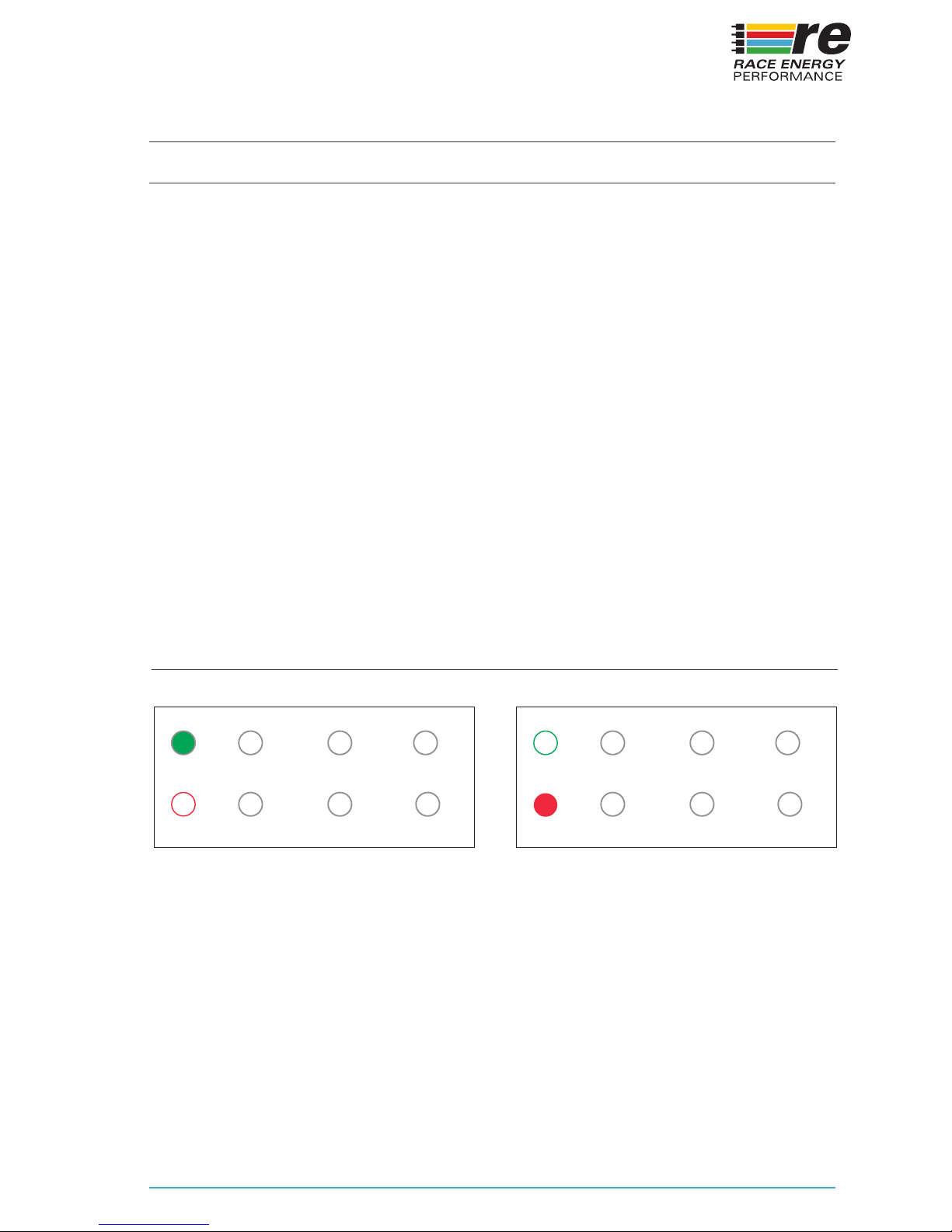
3. Check the polarity indicator light (labelled ‘POL’) on the charger front panel. If it
glows RED, the battery connection in the vehicle is reversed. Stop and correct
the connections to the battery (Red should go to Positive and Black should go
to Negative). After correcting any wiring issue, check that the POL indicator
light is OFF.
4. Plug the charger into any source of AC from 85 to 265 VAC.
5. Press the POWER button to turn the charger ON if necessary (The BCM21
charger remembers its last condition, ON or OFF before AC was disconnected
from the previous use).
Installation Indicators
AC
POL
TEMP
25
DEV
CH
75
FAIL
FLT
LO V
BAT
50
PS
AC Present
AC
POL
TEMP
25
DEV
75
FAIL
FLT
LO V
50
BAT
Battery Polarity Reversed
CH PS
Page 8
8
CONNECTION TO A BATTERY
1. Place the charger in a convenient location close to the battery.
2. Plug the charger cable and the supplied Alligator Clip cable together.
3. Connect the Alligator Clips to the posts of the battery, Red to Positive and
Black to Negative.
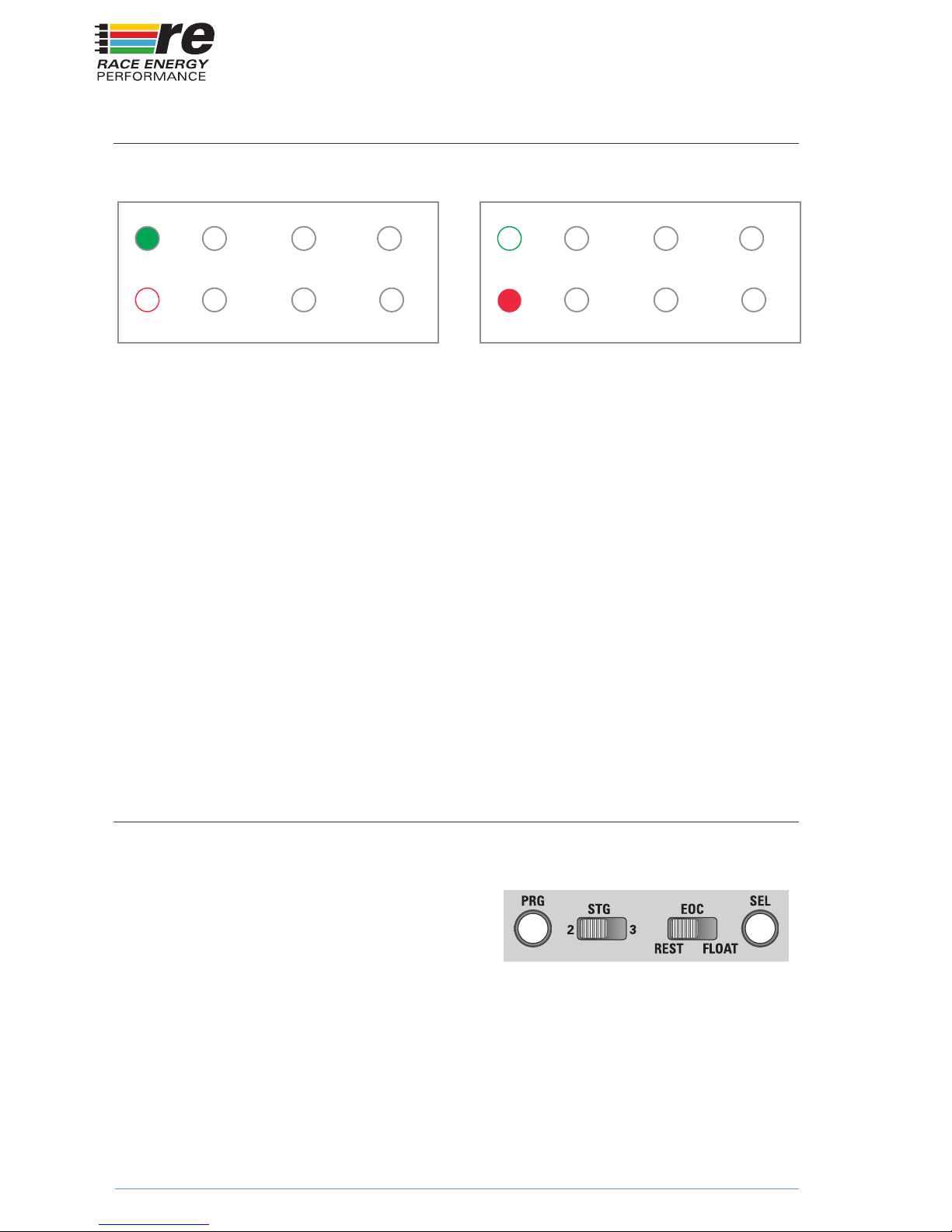
4. Check the polarity indicator light (labelled ‘POL’) on the charger front panel.
If it glows RED, the battery is connected in reverse. Stop and reverse the
connections to the battery (Red should go to Positive and Black should go to
Negative). After correcting any wiring issue, check that the POL indicator light
is OFF.
5. Plug the charger into any source of AC from 85 to 265 VAC.
6. Press the POWER button to turn the charger ON if necessary (The BCM21
Charger remembers its last condition, ON or OFF before AC was disconnected
from the previous use).
Installation Indicators
AC Present Battery Polarity Reversed
AC
POL
TEMP
25
DEV
75
FAIL
FLT
LO V
BAT
50
AC
POL
TEMP
25
DEV
75
FAIL
FLT
LO V
50
BAT
CH PS CH PS
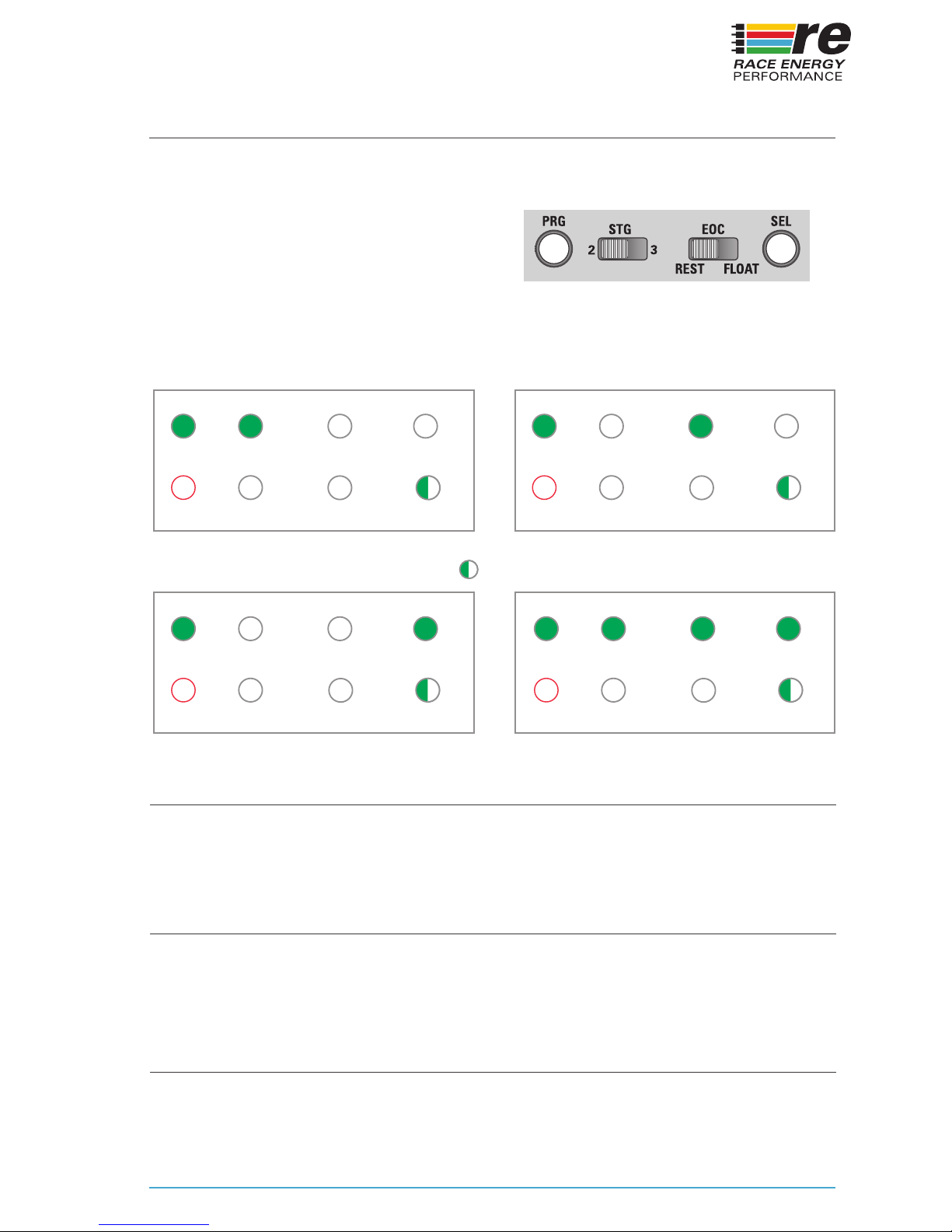
Programming the charger can be accomplished directly on the front panel of the
charger OR through the downloadable ‘PowerWizard’ software.
To program the charger from the front panel
press the Power button on the front panel to
turn the charger ON. The Power button will
illuminate once the charger has turned on.
Enter the programming mode by pressing and holding the PRG button for 3 seconds
until you hear a one second beep and the Charge LED starts blinking.
PROGRAMMING
Page 9

9
BATTERY TYPE
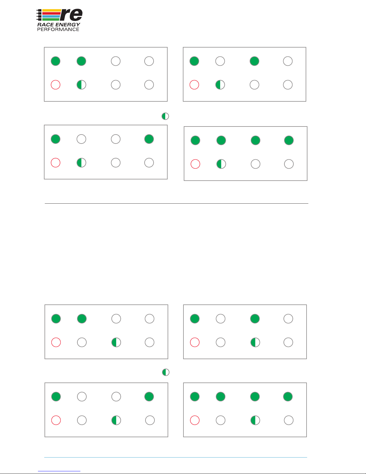
Each press of the Select (SEL) button will advance the battery selection. The three
LED’s on the top will indicate Flooded, AGM and Gel, or Lithium Ion when lit.
Flooded – *The lead–acid battery was invented in 1859 by French physicist Gaston
Planté and is the oldest type of rechargeable battery. Despite having a very low
energy-to-weight ratio and a low energy-to-volume ratio, its ability to supply high
surge currents means that the cells have a relatively large power-to-weight ratio.
These features, along with their low cost, make them attractive for use in motor
vehicles to provide the high current required by motors. This is the Default setting.
AGM – **AGM (Absorbed Glass Mat) batteries differ from ooded lead acid
batteries in that the electrolyte is held in the glass mats, as opposed to freely
ooding the plates. Very thin glass bers are woven into a mat to increase surface
area enough to hold sufcient electrolyte on the cells for their lifetime. The bers
that compose the ne glass mat do not absorb nor are they affected by the acidic
electrolyte.
Gel – **A modern gel battery (also known as a “gel cell”) is a VRLA (Valve Regulated
Lead Acid) battery with a gelied electrolyte; the sulfuric acid is mixed with fumed
silica, which makes the resulting mass gel-like and immobile. Unlike a ooded
wet-cell lead-acid battery, these batteries do not need to be kept upright. Gel
batteries reduce the electrolyte evaporation, spillage (and subsequent corrosion
problems) common to the wet-cell battery, and boast greater resistance to extreme
temperatures, shock and vibration. Chemically they are almost the same as wet
(non-sealed) batteries except that the antimony in the lead plates is replaced by
calcium, and gas recombination can take place.
Custom – This is the mode that can be custom programmed via the USB port using
the PowerWizard software on a laptop for almost any type of battery including
Lithium Ion. From the factory, this is prole is not programmed, and is not available
until it is programmed using the PowerWizard software.
Lithium Ion – ***A lithium-ion battery (sometimes Li-ion battery or LIB) is a member
of a family of rechargeable battery types in which lithium ions move from the
negative electrode to the positive electrode during discharge and back when
charging. Nominal cell voltage is 3.6V and a 12V battery consists of 4 cells in series
to create 14.4V. The charging routine is Constant Current (Bulk Charge) to Constant
Voltage (Float) at 14.4 Volts.
* Wikipedia contributors. “Lead–acid battery.” Wikipedia, The Free Encyclopedia. Wikipedia, The Free Encyclopedia.
** Wikipedia contributors. “VRLA battery.” Wikipedia, The Free Encyclopedia. Wikipedia, The Free Encyclopedia.
*** Wikipedia contributors. “Lithium-Ion battery.” Wikipedia, The Free Encyclopedia. Wikipedia.
Page 10
10
Depending on the size and type of the battery or batteries connected to the
charger, the standard charging current output of the charger may be more than
is optimal or recommended. Refer to the documentation from your battery
manufacturer to determine the maximum safe charging current. If needed, the
maximum charging current can be reduced to 25, 50 or 75 percent of the rated
output of the charger. The three LED’s on the top will indicate 25%, 50% and 75%
respectively. All three LED’s will be simultaneously lit to indicate 100% charging
current (Default). The Power Limit (Bulk Charging Current) can be customized
down to the nearest Amp using the PowerWizard software.
POWER LIMIT
Battery Type Indicators
AC
POL
FLOODED
BAT
TYPE
GEL
AGM
Flooded Lead Acid
AC
POL
FLOODED
BAT
TYPE
GEL
AGM
Gel
AC CUSTOM
POL
BAT
TYPE
Lithium-Ion
BLINKING
AC
POL
FLOODED
BAT
TYPE
GEL
AGM
Absorbed Glass Mat
Charge Power Indicators
AC
POL
25%
POWER
LIMIT
75%
50%
Max Current 25% of Rated
AC
POL
25%
POWER
LIMIT
75%
50%
Max Current 75% of Rated
BLINKING
POL
Max Current 50% of Rated
AC
25%
75%
50%
POWER
LIMIT
POL
Max Current 100% of Rated
AC
25%
75%
50%
POWER
LIMIT
Page 11
11
The recommended charging voltage for any type of battery will vary with temperature.
The warmer the battery, the lower the charging voltage required. The three top
LED’s indicate Cold, Warm, Hot and Auto.
Cold, Warm and Hot and correspond
to battery temperatures of 10, 25 or 35
degrees Celsius respectively (50, 77 or 95
Fahrenheit). In Auto, the charger measures
its own internal temperature during startup, and estimates the batteries to be the
same temperature and applies the appropriate compensation (Default).
DEFAULT BATTERY TEMPERATURE
Default Battery Temperature Indicators
POL
BAT
TEMP
AC COLD HOTWARM
Default Battery Temp 10C
BLINKING
Auto Battery Temp
POL
Default Battery Temp 25C
BAT
TEMP
AC COLD HOTWARM
POL POL
Default Battery Temp 35C
BAT
TEMP
BAT
TEMP
AC COLD HOTWARM AC COLD HOTWARM
SAVING
EXIT WITHOUT SAVING
FULL RESET
To save the conguration and exit Setup at any point in the process, press and hold
the Program (PRG) button for 3 seconds until you hear a one second beep.
To exit without saving, either press the On/Off button or do nothing. The charger
will exit the conguration mode without changing the stored conguration after 60
seconds elapses without any button being pressed.
To restore the charger to its factory default settings, enter the programming mode
by pressing and holding the PRG button for 3 seconds until you hear a one second
beep and the Charge LED starts blinking. Then press and hold both the PRG and
SEL buttons for 10 seconds until you hear multiple beeps.
Page 12
12
FRONT PANEL ADJUSTMENTS
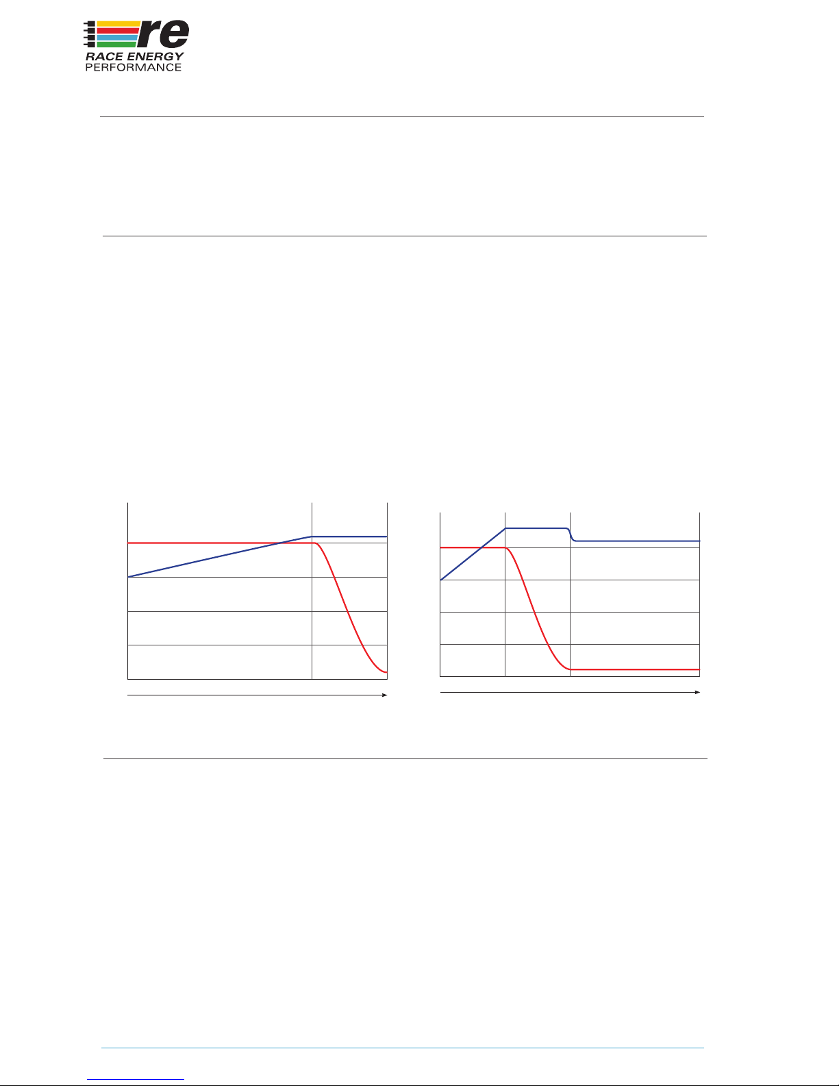
2 STAGE / 3 STAGE (STG) PROFILE SELECT
Two additional adjustments can be made from the front panel. These are to select
the charging prole as well as the behavior of the charger at the conclusion of a
recharge cycle.
The switch on the left selects a 2 Stage or 3 Stage charging prole.
A 2 Stage charging prole consists of charging the battery at a constant current
(Bulk Charge) until the battery voltage reaches the Float Voltage. The charger will
then maintain the battery at the Float Voltage and the current will gradually taper
down. The recharge is considered complete when the charging current drops to
10% of the rated current of the charger.
A 3 Stage charging prole consists of charging the battery at a constant current
(Bulk Charge) until the battery voltage reaches an elevated voltage called the
‘Absorption Voltage’. The charger will then maintain the battery at the Absorption
Voltage until the charging current drops to 10% of the rated current of the charger
OR a maximum of 3 hours.
100%
75%
50%
25%
0%
Bulk
(Constant Current)
Maintenance
(Constant Volts)
Time
Two Stage Charger
Volts
Amps
100%
75%
50%
25%
0%
Bulk
(Constant Current)
Absorption
(Constant Volts)
Maintenance
(Constant Volts)
Time
Three Stage Charger
Volts
Amps
END OF CHARGE (EOC) FUNCTION SELECT
The switch on the right tells the Charger what to do when recharging is complete.
Moving the switch to the Left tells the charger to Rest or switch to Standby when
the recharge is complete. The charger will remain in Standby until the power is
cycled with the Power Switch or by unplugging and re-plugging the power cord
OR until the battery voltage drops to 90% of the rated voltage of the battery.
Under any of these conditions, the charger will initiate a new recharge cycle. This
is the position the switch MUST be in to meet the California Energy Commission
regulations.
Moving the switch to the Right tells the charger to maintain the battery at the Float
Voltage indenitely. This will ensure that the battery is always fully recharged and
ready for service. A new recharge cycle will be initiated only if the charger is unable
to maintain the battery at the Float Voltage OR by cycling the power as described
above.
Page 13

13
OPERATION
Operation of the BCM21 charger is very simple. It is intended to operate fully
unattended, and will attempt to recover from any fault, such as Charger OverTemperature, Battery Over-Temperature, Insufcient Input Voltage, Power Failure
and more.
In a xed installation, presumably the charger is already connected to the battery or
batteries. In a portable application, connect the charger to the battery before turning
it on. Once the battery is connected to the charger, conrm that the ‘REV’ LED is
NOT illuminated and that the ‘AC’ LED is illuminated (Green) and press the Power
button on the front panel.
Note: The charger has two operating modes – Battery
Charger and Power Supply. If you are not sure which mode
the BCM21 is in, press and hold the lighted Power button
for 3 seconds. If you hear two beeps, it is in Power Supply
mode. If you hear one beep, it is in Battery Charger mode.
Make sure it is in the correct operating mode for your
requirements
The charger will go through a startup sequence that consists of turning the 6 LEDs
controlled by the computer all Red, then all Green. The Power button will illuminate
once the charger has completely turned on.
The charger will begin to charge the battery or batteries according to the settings
that were selected during programming. If no battery was detected during the
startup of the charger, it will not turn the outputs on and will indicate a failure. As
soon as a battery is detected, normal operation will resume.
If the AC power fails or is disconnected, the charger will resume charging the
batteries when AC is restored.
In high ambient temperatures, the BCM21 Charger will reduce its power output as
needed to keep the circuitry operating at a safe and reliable temperature. In extreme
cases, the charger may shut off completely until it cools sufciently to resume
operation.
Page 14
14
EQUALIZE CYCLE
The equalize cycle is not supported by the BCM21 charger as it doesn’t have a
battery temperature sensor. There is no way to safely perform this charging cycle
without battery temperature information.
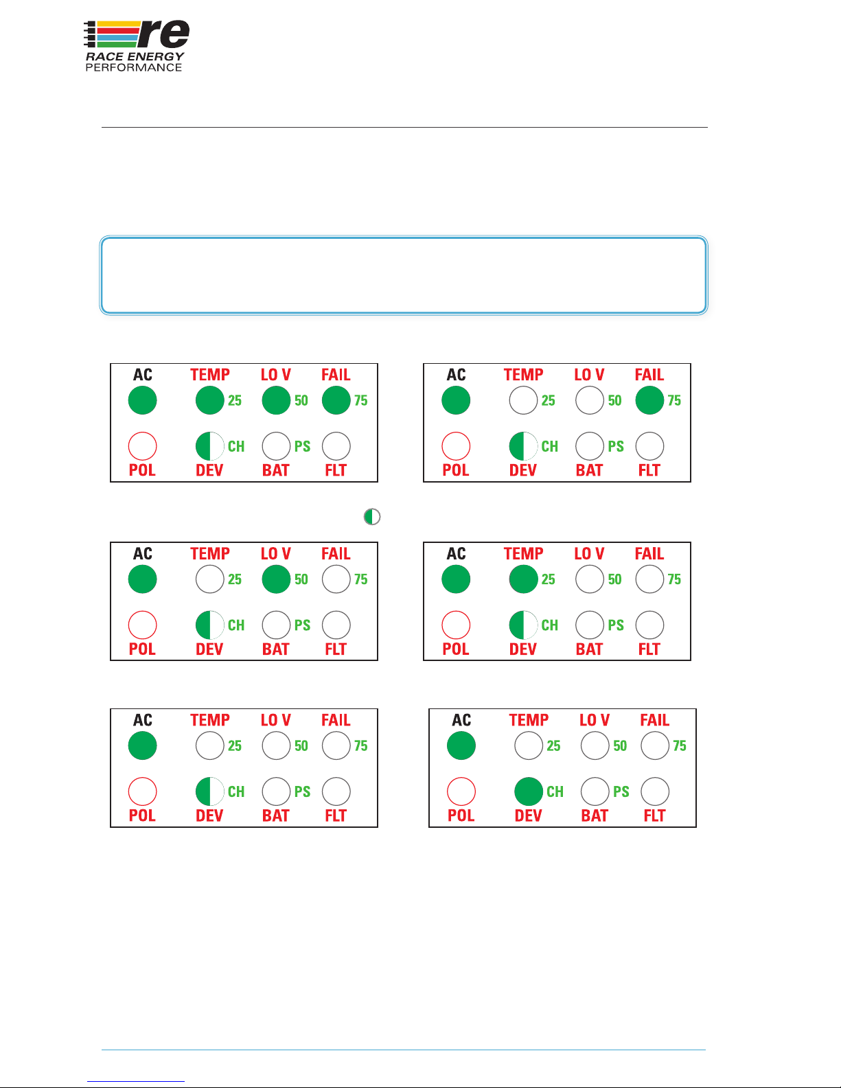
Charging Indicators
BLINKING
Charging Current > 85% Charging Current 60 - 84%
Charging Current > 40 - 59% Charging Current 11 - 39%
Note: The outputs of the charger can be forced ON by
switching it to Power Supply mode described above.
Charging Current 1 - 10% Charge Complete
Page 15
15
POWER SUPPLY MODE
The BCM21 charger can be switched to Power Supply Mode at any time by
pressing and holding the Power button for 3 seconds until you hear 2 beeps. This
changes the operation of the charger in the following ways.
1. The outputs will turn on regardless of whether a battery is detected or not.
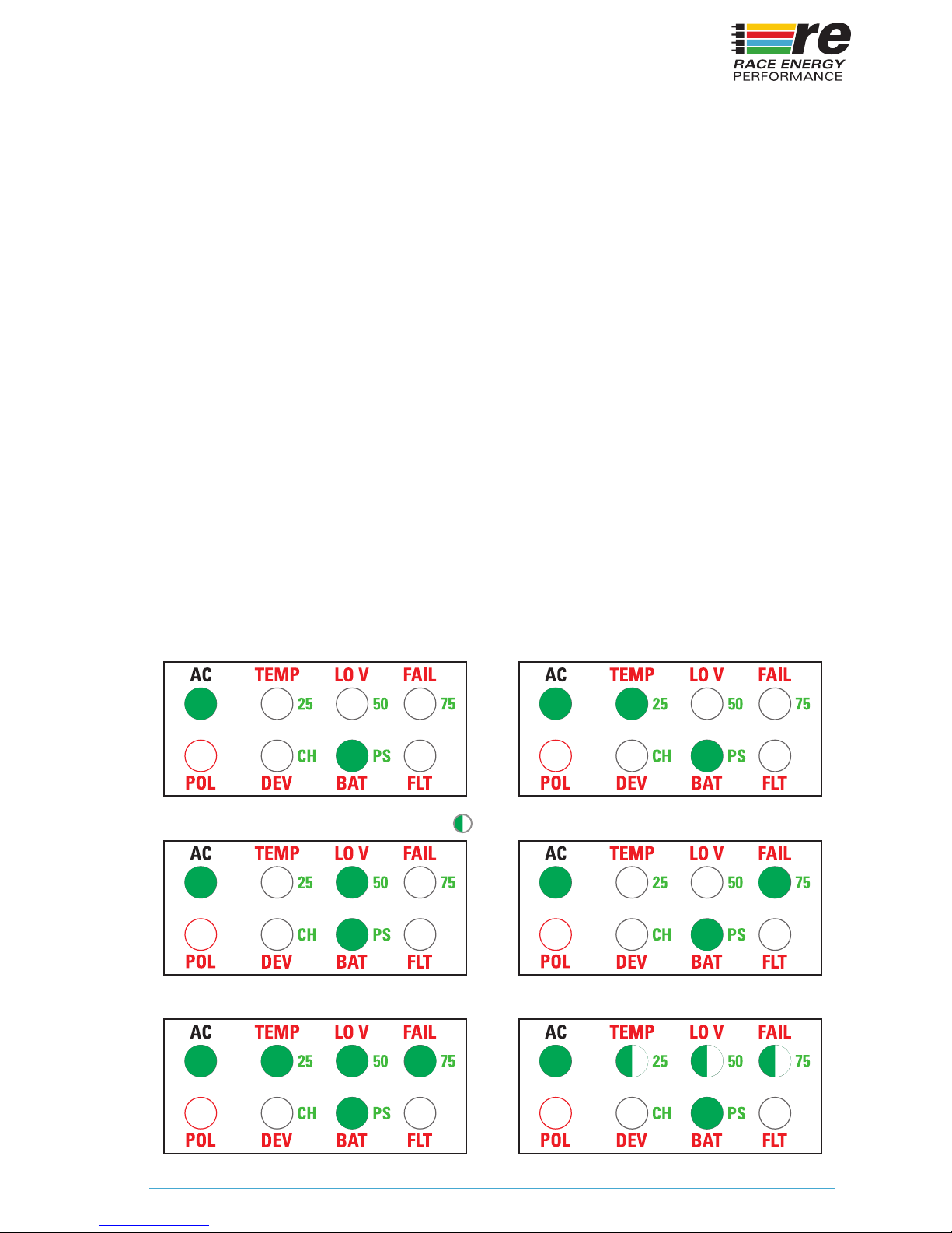
2. The Output Power indicator LEDs will all blink any time the output current
reaches 100%.
3. The output voltage is xed at the oat voltage for the battery type selected
during Setup (in case there is a battery connected).
4. The EOC switch and 2-3 Stage switch have no function.
5. There is no Equalize mode.
6. By use of the Power Wizard PC software, it is possible to customize the output
voltage in Power Supply mode within the working range of the unit. Use the
Power Wizard software to program the oat voltage in any of the 4 proles to
a voltage between 12.0 and 15.0 volts, name the prole “Power Supply” and
select that prole to be active.
The charger will remain in Power Supply mode until switched back to Charger
mode by pressing and holding the Power button for 3 seconds again until you hear
1 beep
Power Supply Indicators
BLINKING
Current < 10% Current 11 - 39%
Current > 40 - 59%
Current > 85%
Current 60 - 84%
Current = 100%
Page 16

16
MAINTENANCE
The charger requires no maintenance other than the occasional wipe down to
remove dust that could reduce its ability to dissipate heat.
Page 17

17
TROUBLESHOOTING
The BCM21 charger is designed to provide years of reliable service. However in the
event that it does not seem to be operating correctly, here are some things you can
check.
AC PRESENT LED DOES NOT COME ON.
First make sure any external circuit breaker is ON. Unplug or turn off the external
power to the charger. Plug any other device into the AC receptacle or use a
multimeter to make sure AC is present. Remove the fuse and check for continuity
with a multimeter. If the fuse is open, replace it with the recommended fuse listed
on the label and reconnect or turn the power back on. The AC Present LED should
come on. If it does not, then there is an internal failure and the charger will have to
be returned for service.
BATTERY OVERTEMP INDICATION
If the battery gets too hot during charging, the charger will stop and wait for the
battery to cool sufciently before resuming charging. If this happens frequently,
particularly in relatively normal ambient temperatures, the battery is likely damaged
or defective and should be replaced.
BATTERY LOW VOLTAGE INDICATION
If the battery is seriously discharged, and the charger voltage drops below 85% of
nominal (ie. 10V for a 12V charger), the charger will alternate between its normal
display and the Low Battery Voltage display until the battery voltage exceeds 85%
of nominal.
BATTERY FAIL INDICATION
If the charger determines that the battery is defective and will not accept a charge,
the charger will stop attempting to charge the battery. This condition requires action
on the part of the user to replace the battery before the charger will resume normal
operation. Cycling the power switch to Off and back On again in any way will reset
this condition and the charger will attempt to recharge the battery again.
CHARGER OVERTEMP
If the charger gets too hot, it will switch to Standby until it cools sufciently to
resume normal operation.
LOW INPUT VOLTS
If the input voltage drops below the minimum voltage necessary for normal
operation, the charger will show this display. The charger will switch to Standby
and wait for the voltage to recover
Page 18
18
CHARGER FAILED
If the processor detects a condition that prevents the charger from operating,
it will show this display. Try unplugging and re-plugging the power a couple of
times to see if that clears the problem. If it does not clear the display the charger
will have to be returned for repair. More information on the nature of the fault can
be determined by connecting to the charger using a laptop and using the Power
Wizard program to see if a more detail error message is there
CHARGER IN WRONG MODE
The charger may be in Power Supply mode instead of Battery Charger mode. Make
sure the charger is in the Battery Charging mode by pressing the Power button for
3 seconds until you hear 1 beep. If you hear 2 beeps, repeat until you hear 1 beep.
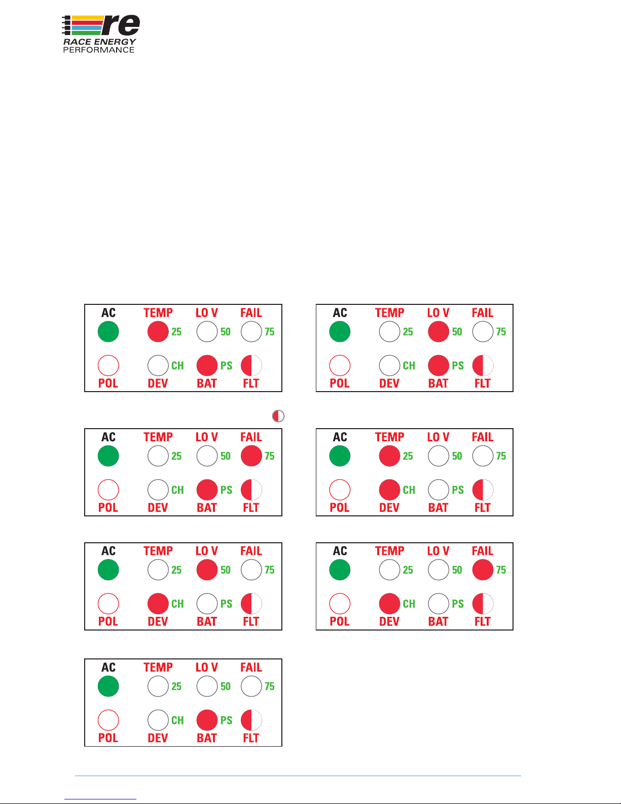
Fault Indicators
BLINKING
Battery Overtemp Battery Lo Voltage
Battery Failed
Charger Lo Input Volts
No Battery
Charger Overtemp
Charger Failed
Page 19

19
ABBREVIATIONS AND DEFINITIONS
We use a number of abbreviations on the labels to save space. Here are the full
words corresponding to each abbreviation along with common battery charger
terms and their denitions:
ABBREVIATIONS
POL – Polarity. Refers to the correct connection of the Positive and Negative
terminals of the battery to the charger.
DEV – Device. Refers to the charger. Used together with the Fault LED to indicate a
problem with the Device.
BAT – Battery. Refers to the battery. Used together with the Fault LED to indicate a
problem with the Battery.
FLT – Fault. Used to indicate a problem with the battery (BAT) or the device (DEV)
AC – Alternating Current
TEMP – Temperature. Used to indicate that either the Battery or the Device is too
hot.
LO V – Low Voltage. Used to indicate that either the Input Voltage or the Battery
Voltage is too low.
FAIL – Used to indicate that either the battery or the device needs repair or
replacement.
PRG – Program - Button used to initiate the Programming Mode
STG – Stage – Switch used to select between 2-Stage or 3-Stage charging prole
EOC – End Of Charge – Switch used to select Rest or Float at the end of a charge
cycle
SEL – Select – Button used to make choices during front panel programming
CH – Charging
EQ – Equalize
PS – Power Supply
DEFINITIONS
CC – Constant Current. Typically the rst phase of a recharge cycle where a
constant current is delivered to the battery until the voltage reaches a specic level.
CV – Constant Voltage. Typically the 2nd or 3rd phases of a recharge cycle where
the battery voltage is maintained at a constant level.
Absorption – The rst Constant Voltage stage in a 3 stage charging algorithm,
where the battery is maintained at an elevated voltage for a period of time to ensure
full and equal recharging of all cells.
Page 20

20
Equalize – A deliberate overcharge at low current to bring a weak cell up to the
same charge level as the good cells in a weak battery. Typically only performed once
every few months, and only if battery exhibits reduced capacity.
Float – The second and nal Constant Voltage stage in a 3 stage charging algorithm,
or the only Constant Voltage stage in a 2 stage algorithm where the battery is held
at safe voltage indenitely.
Amp-Hour Capacity – The energy capacity of a battery expressed in the number of
hours the battery can last a specic output current. For example, 100 Amp-Hours
means that a battery can supply 100 amps for 1 hour, or 10 amps for 10 hours, etc.
C/20 Rate – The number of amps that a battery can supply for 20 hours. For
example a 100 amp hour battery should be able to supply 5 amps continuously for
20 hours. Battery capacity varies with the discharge rate. The higher the discharge
rate, the lower the capacity of the battery.
Deep Discharge Battery – a battery designed to have a lower maximum current
capability, but can be repeatedly deeply discharged without damaging it or seriously
affecting its lifespan.
Engine Starting Battery – a battery designed to produce a very high amperage for
engine starting, but typically does not tolerate repeated deep discharging.
Page 21

21
Page 22

22
Page 23

23
LIMITED WARRANTY
1. The equipment manufactured by Analytic Systems Ware (1993) Ltd. (the “Warrantor”) is
warranted to be free from defects in workmanship and materials under normal use and
service.
2. This warranty is in effect for ve (5) years from the date of purchase by the end user.
3. Analytic Systems will determine eligibility for warranty from the date of purchase shown on
the warranty card when returned within 30 days, or
a. The date of shipment by Analytic Systems, or
b. The date of manufacture coded in the serial number, or
c. From a copy of the original purchase receipt showing the date of purchase by the user.
4. In case any part of the equipment proves to be defective, the Purchaser should do the
following:
a. Prepare a written statement of the nature of the defect to the best of the Purchasers
knowledge, and include the date of purchase, the place of purchase, and the Purchasers
name, address and telephone number.
b. Call Analytic Systems at 800-668-3884 or 604-946-9981 and request a return material
authorization number (RMA).
c. Return the defective part or unit along with the statement at the Purchasers expense to
the Warrantor; Analytic Systems Ware (1993) Ltd., 8128 River Way, Delta, B.C., V4G 1K5,
Canada.
5. If upon the Warrantor’s examination the defect proves to be the result of defective material or
workmanship, the equipment will be repaired or replaced at the Warrantor’s option without
charge, and returned to the Purchaser at the Warrantor’s expense by the most economical
means. Requests for a different method of return or special handling will incur additional
charges and are the responsibility of the Purchaser.
6. Analytic Systems reserves the right to void the warranty if:
g. Labels, identication marks or serial numbers are removed or altered in any way.
h. Our invoice is unpaid.
i. The defect is the result of misuse, neglect, improper installation, environmental
conditions, non-authorized repair, alteration or accident.
10. No other express warranty is hereby given and there are no warranties that extend beyond
those described herein. This warranty is expressly in lieu of any other expressed or implied
warranties, including any implied warranty of merchantability, tness for the ordinary
purposes for which such goods are used, or tness for a particular purpose, or any other
obligations on the part of the Warrantor or its employees and representatives.
11. There shall be no responsibility or liability whatsoever on the part of the Warrantor or its
employees and representatives for injury to any person or persons, or damage to property,
or loss of income or prot, or any other consequential or resulting damage which may be
claimed to have been incurred through the use or sale of the equipment, including any
possible failure of malfunction of the equipment, or part thereof.
12. The Warrantor assumes no liability for incidental or consequential damages of any kind.
Page 24

Revised February 18, 2015
8128 River Way, Delta B.C. V4G 1K5 Canada
T. 604.946.9981 F. 604.946.9983 TF. 800.668.3884 (US/CANADA)
www.RaceEnergyPerformance.com
MOTORSPORTS SOLUTIONS
 Loading...