


User Manual
3151/3151A
WAVEFORM GENERATOR
Publication No. 980768
RACAL INSTRUMENTS
Racal Instruments, Inc.
Tel: (800) RACAL-ATE, (800) 722-2528, (949) 859-8999; FAX: (949) 859-7139
4 Goodyear St., Irvine, CA 92618-2002
480 Bath Road, Slough, Berkshire, SL1 6BE, United Kingdom
Tel: +44 (0) 1628 604455; FAX: +44 (0) 1628 662017
18 Avenue Dutartre, 78150 LeChesnay, France
Tel: +33 (1) 3923 2222; FAX: +33 (1) 3923 2225
Strada 2-Palazzo C4, 20090 Milanofiori Assago, Milan, Italy
Tel: +39 (0)2 5750 1796; FAX +39 (0)2 5750 1828
Technologiepark Bergisch Gladbach, Friedrich-Ebert-Strasse, D-51429 Bergisch Gladbach, Germany
Tel.: +49 2204 8442 00; FAX: +49 2204 8442 19
3 Powells Road, Brookvale, NSW 2100, Australia
Tel: +612 9936 7000, FAX: +612 9936 7036
26 Ayer Rajah Crescent, 04-06/07 Ayer Rajah Industrial Estate, Singapore 0513.
Unit 5, 25F., Mega Trade Center, No 1, Mei Wan Road, Tsuen Wan, Hong Kong, PRC
Tel: +852 2405 5500, FAX: +852 2416 4335
Racal Instruments, Ltd.
Racal Systems Electronique S.A.
Racal Systems Elettronica s.r.l.
Racal Elektronik System GmbH.
Racal Australia Pty. Ltd.
Racal Electronics Pte. Ltd.
Tel: +65 7792200, FAX: +65 7785400
Racal Instruments, Ltd.
http://www.racalinstruments.com
Copyright 2000 by Racal Instruments, Inc. Printed in the United States of America. All rights reserved.
This book or parts thereof may not be reproduced in any form without written permission of the publisher.
PUBLICATION DATE: July 25, 2000

WARRANTY STATEMENT
All Racal Instruments, Inc. products are designed and manufactured to exacting standards and in full
conformance to Racal’s ISO 9001 procedures.
For the specific terms of your standard warranty, or optional extended warranty or service agreement, contact
your Racal customer service advisor. Please have the following information available to facilitate service.
1. Product serial number
2. Product model number
3. Your company and contact information
You may contact your customer service advisor by:
E-Mail: Helpdesk@racalinstruments.com
Telephone: +1 800 722 3262 (USA)
+44(0) 8706 080134 (UK)
+852 2405 5500 (Hong Kong)
Fax: +1 949 859 7309 (USA)
+44(0) 1628 662017 (UK)
+852 2416 4335 (Hong Kong)
RETURN of PRODUCT
Authorization is required from Racal Instruments before you send us your product for service or calibration. Call
your nearest Racal Instruments support facility. A list is located on the last page of this manual. If you are
unsure where to call, contact Racal Instruments, Inc. Customer Support Department in Irvine, California, USA at
1-800-722-3262 or 1-949-859-8999 or via fax at 1-949-859-7139. We can be reached at:
helpdesk@racalinstruments.com.
PROPRIETARY NOTICE
This document and the technical data herein disclosed, are proprietary to Racal Instruments, and shall not,
without express written permission of Racal Instruments, be used, in whole or in part to solicit quotations from a
competitive source or used for manufacture by anyone other than Racal Instruments. The information herein has
been developed at private expense, and may only be used for operation and maintenance reference purposes or
for purposes of engineering evaluation and incorporation into technical specifications and other documents which
specify procurement of products from Racal Instruments.

FOR YOUR SAFETY
Before undertaking any troubleshooting, maintenance or exploratory procedure, read carefully the
WARNINGS and CAUTION notices.
This equipment contains voltage hazardous to human life and safety, and is capable of inflicting
personal injury.
If this instrument is to be powered from the AC line (mains) through an autotransformer, ensure the
common connector is connected to the neutral (earth pole) of the power supply.
Before operating the unit, ensure the conductor (green wire) is connected to the ground (earth)
conductor of the power outlet. Do not use a two-conductor extension cord or a three-prong/twoprong adapter. This will defeat the protective feature of the third conductor in the power cord.
Maintenance and calibration procedures sometimes call for operation of the unit with power applied
and protective covers removed. Read the procedures and heed warnings to avoid “live” circuit
points.
Before operating this instrument:
1. Ensure the instrument is configured to operate on the voltage at the power source. See
Installation Section.
2. Ensure the proper fuse is in place for the power source to operate.
3. Ensure all other devices connected to or in proximity to this instrument are properly grounded or
connected to the protective third-wire earth ground.
If the instrument:
- fails to operate satisfactory
- shows visible damage
- has been stored under unfavorable conditions
- has sustained stress
Do not operate until performance is checked by qualified personnel.

This page was left intentionally blank.

3151 And 3151A User Manual
Table of Contents
Chapter 1
Getting Started..................................................................................................................................1-1
What’s In This Chapter ..................................................................................................................1-1
Introduction.....................................................................................................................................1-1
Options...........................................................................................................................................1-3
Manual Changes............................................................................................................................1-4
Safety Considerations....................................................................................................................1-4
Supplied Accessories.....................................................................................................................1-5
Specifications.................................................................................................................................1-5
Functional Description....................................................................................................................1-5
Input and Output Connectors.....................................................................................................1-5
Main Output.............................................................................................................................1-5
SYNC Output ..........................................................................................................................1-6
External Clock Input................................................................................................................1-6
Reference Clock Output .........................................................................................................1-6
Trigger Input............................................................................................................................1-6
Operating Modes........................................................................................................................1-7
Continuous Mode....................................................................................................................1-7
Triggered Mode.......................................................................................................................1-7
Burst Mode..............................................................................................................................1-7
Gated Mode ............................................................................................................................1-8
Output Type................................................................................................................................1-8
Standard Waveforms..............................................................................................................1-8
Arbitrary Waveforms...............................................................................................................1-8
Sequenced Waveforms..........................................................................................................1-8
Output State..............................................................................................................................1-10
Synchronization ........................................................................................................................1-10
Filter..........................................................................................................................................1-10
Front Panel Indicators ..............................................................................................................1-11
Programming The Model 3151/3151A.........................................................................................1-11
Chapter 2
i

3151 And 3151A User Manual
Configuring The Instrument..............................................................................................................2-1
Installation Overview......................................................................................................................2-1
Unpacking and Initial Inspection.................................................................................................2-1
Safety Precautions.........................................................................................................................2-1
Performance Checks......................................................................................................................2-2
Grounding
Requirements ...........................................................................................................2-2
Long Term Storage or Repackaging For Shipment...................................................................2-3
Preparation For Use.......................................................................................................................2-3
Logical Address Selection..........................................................................................................2-4
Installation...............................................................................................................................2-6
Chapter 3
Using The Instrument .......................................................................................................................3-1
Overview.........................................................................................................................................3-1
Output Termination.....................................................................................................................3-1
Input/Output
Protection...............................................................................................................3-1
Power On/Reset Defaults...........................................................................................................3-1
What To Do Now............................................................................................................................3-2
Using the APPLy Command ..........................................................................................................3-3
Output Configuration Commands ..................................................................................................3-8
Selecting an Output
Function Type............................................................................................3-8
Selecting a Standard
Function Shape........................................................................................3-8
Changing the Frequency and Sample Clock..............................................................................3-9
Selecting the Sample Clock Source.........................................................................................3-10
Programming the Output Amplitude and Offset.......................................................................3-10
Selecting the Filter Type...........................................................................................................3-11
Activating the
Assigning the Validating
Backplane ECLTRG and TTLTRG....................................................................3-12
Source For TTLTRG.....................................................................3-13
Enabling the Main Output.........................................................................................................3-13
Enabling the Sync Output.........................................................................................................3-14
Assigning the Source For The SYNC Output.......................................................................3-14
Selecting the SYNC Position ................................................................................................3-15
Using the Built-In Standard Waveforms...................................................................................3-16
Selecting an Operating Mode.......................................................................................................3-19
Triggered Mode ........................................................................................................................3-19
ii

3151 And 3151A User Manual
Gated Mode..............................................................................................................................3-19
Burst Mode................................................................................................................................3-20
Selecting the Trigger Source........................................................................................................3-21
Using the Internal Trigger Generator........................................................................................3-22
Selecting the Trigger Slope..........................................................................................................3-23
Using the Soft Trigger..................................................................................................................3-23
Generating Arbitrary Waveforms .................................................................................................3-24
What Are Arbitrary Waveforms? ..............................................................................................3-24
Arbitrary Memory Management................................................................................................3-24
Memory Management Commands...........................................................................................3-24
Loading Arbitrary Waveforms...................................................................................................3-26
Reversing Byte Order............................................................................................................3-28
Using Shared Memory ..........................................................................................................3-28
Sequence..................................................................................................................................3-30
Generating Sequenced Waveforms.............................................................................................3-31
What Are Sequenced Waveforms?..........................................................................................3-31
Sequence Commands..............................................................................................................3-33
High Speed Sequence Downloads (3151A Only)....................................................................3-35
Triggered Sequence Advance..................................................................................................3-37
Triggered Sequence Advance Commands..............................................................................3-38
Inter-Module Synchronization.......................................................................................................3-39
Synchronization............................................................................................................................3-39
Amplitude Modulation Commands ...........................................................................................3-41
System-Related Commands.....................................................................................................3-42
Chapter 4
SCPI Command Reference..............................................................................................................4-1
What’s In This Chapter ..................................................................................................................4-1
Introduction To SCPI Language.....................................................................................................4-1
Command Format.......................................................................................................................4-2
Command Separator..................................................................................................................4-3
The MIN and MAX Parameters...............................................................................................4-3
Querying Parameter Setting.......................................................................................................4-4
Query Response Format.........................................................................................................4-4
SCPI Command Terminator.......................................................................................................4-4
iii

3151 And 3151A User Manual
IEEE-STD-488.2 Common Commands.........................................................................................4-4
SCPI Parameter Type.................................................................................................................4-5
Numeric Parameters...............................................................................................................4-5
Discrete Parameters...............................................................................................................4-5
Boolean Parameters...............................................................................................................4-5
Arbitrary Block
Parameters.....................................................................................................4-6
SCPI Command Summary.........................................................................................................4-6
Output Configuration Command Summary................................................................................4-9
Standard Waveform Command Summary...............................................................................4-11
Arbitrary Waveform, Sequence, and Shared Memory Command Summary...........................4-12
Modulation Command Summary..............................................................................................4-12
Trigger Command
Summary.....................................................................................................4-13
Inter-Module Phase Synchronization Command Summary.....................................................4-13
System-Related Command Summary......................................................................................4-14
IEEE-STD-488.2 Common Commands and Queries ..............................................................4-14
The SCPI Status Registers.......................................................................................................4-16
The Status Byte
Register (STB)...............................................................................................4-18
Reading the Status Byte Register.........................................................................................4-18
Clearing the Status Byte Register.........................................................................................4-19
Service Request Enable
Standard Event
Status Register (ESR) ................................................................................4-20
Register (SRE)..............................................................................4-19
Standard Event Status Enable Register (ESE)....................................................................4-21
Error Messages............................................................................................................................4-21
Device-Specific Commands.........................................................................................................4-23
Chapter 5..........................................................................................................................................5-1
Maintenance and Performance Checks...........................................................................................5-1
What’s in This Chapter...................................................................................................................5-1
Disassembly
Special Handling of Static Sensitive
Instructions............................................................................................................5-1
Devices.............................................................................5-2
Cleaning......................................................................................................................................5-2
Repair and
Replacement............................................................................................................5-3
Performance Checks..................................................................................................................5-3
Environmental Conditions.......................................................................................................5-4
Warm-Up Period.....................................................................................................................5-4
iv

3151 And 3151A User Manual
Initial Instrument Setting .........................................................................................................5-4
Recommended Test Equipment.............................................................................................5-5
Performance Check Procedures................................................................................................5-5
Frequency Accuracy ...............................................................................................................5-6
Amplitude Accuracy ................................................................................................................5-7
DC Offset Characteristics.......................................................................................................5-8
Squarewave Characteristics...................................................................................................5-9
Sine Characteristics..............................................................................................................5-10
Sine Flatness ........................................................................................................................5-11
Trig, Gate and Burst
Characteristics ....................................................................................5-12
Adjustments..............................................................................................................................5-14
Environmental Conditions.....................................................................................................5-14
Warm-Up Period...................................................................................................................5-14
Recommended Test
Equipment...........................................................................................5-14
Adjustment Procedures.........................................................................................................5-14
Pulse Response Adjustment.................................................................................................5-15
Amplitude Adjustment...........................................................................................................5-16
Offset Adjustment .................................................................................................................5-17
Troubleshooting............................................................................................................................5-18
Recommended Test Equipment...............................................................................................5-18
Power-Up Tests........................................................................................................................5-18
Self-Test....................................................................................................................................5-18
Main Board Circuit Checkout....................................................................................................5-19
Power Supply Checkout ...........................................................................................................5-19
CPU and VXI ASIC Checkout...................................................................................................5-20
Output Amplifier and Amplitude Control Checkout ..................................................................5-21
Clock Synthesizer
Checkout.....................................................................................................5-22
Sequence Generator Checks...................................................................................................5-23
Engine Board Circuit Checkout................................................................................................5-24
Engine Board Checkout........................................................................................................5-24
Chapter 6
OPTIONAL HARNESS ASSEMBLIES.............................................................................................6-1
Chapter 7
PRODUCT SUPPORT .....................................................................................................................7-1
v

3151 And 3151A User Manual
Product Support .............................................................................................................................7-1
Reshipment Instructions.................................................................................................................7-1
Support Offices...............................................................................................................................7-2
Appendix A
Specifications...................................................................................................................................A-1
vi

3151 And 3151A User Manual
List of Figures
Figure 1-1, 3151 and 3151A Front Panel..........................................................................................1-2
Figure 1-2, Segment 1 - Sin(x)/x Waveform......................................................................................1-9
Figure 1-3, Segment 2 - Sine Waveform...........................................................................................1-9
Figure 1-4, Segment 3 - Pulse Waveform.........................................................................................1-9
Figure 1-5, Sequenced Waveforms.................................................................................................1-10
Figure 2-1, Set The Logical Address.................................................................................................2-5
Figure 3-1, Definite Length Arbitrary Block Data Format ................................................................3-27
Figure 3-2, 12-Bit Waveform Data Format......................................................................................3-28
Figure 3-3, Sin(x)/x Waveform Loaded Into Segment 1..................................................................3-31
Figure 3-4, Sine Waveform Loaded Into Segment 2.......................................................................3-32
Figure 3-5, Pulse Waveform Loaded Into Segment 3.....................................................................3-32
Figure 3-6, Sequenced Waveforms - Continuous Advance Mode..................................................3-33
Figure 3-7, Fast Sequence Download.............................................................................................3-36
Figure 3-8, Sequenced Waveforms - Triggered Advance Mode ....................................................3-38
Figure 4-1, SCPI Status Registers...................................................................................................4-17
vii

3151 And 3151A User Manual
List of Tables
Table 3-1, Default Conditions After Power On, RESet or *RST........................................................3-2
Table 3-2, Amplitude and Offset Ranges..........................................................................................3-3
Table 5-1, CPU and VXI Interface Checkout Procedure.................................................................5-20
Table 5-2, Output Amplifier and Amplitude Control Checkout Procedure ......................................5-21
Table 5-3, Clock Synthesizer Checkout Procedure.........................................................................5-22
Table 5-4, Sequence Generator Checkout Procedure....................................................................5-23
Table 5-5, Burst Generator Checks.................................................................................................5-24
Table 5-6b, Engine Board Checkout Procedure - #2......................................................................5-26
Table 5-6c, Engine Board Checkout Checkout Procedure - #3......................................................5-26
viii

3151 And 3151A User Manual
Chapter 1
Getting Started
What’s In This
Chapter
Introduction
This chapter contains a general description of the VXIbus Model
3151/3151A Waveform Generator and an overall functional
description of the instrument. It lists and describes various options
available for this model. It also describes the Model 3151/3151A
front panel connectors and indicators.
NOTE
The Model 3151A is fully hardware and software
compatible with the Model 3151. It may replace any 3151
module. Any features mentioned in this manual are
compatible with both models except where stated
otherwise..
A detailed functional description is given following the general
description of the features, functions, and options available with the
Model 3151/3151A.
The Model 3151/3151A is a VXIbus, single slot C-size module.
Waveform Generator. It is a high performance waveform generator
that combines two powerful instruments in one small package; a
function generator and an arbitrary waveform generator. The
instrument provides a variety of standard waveforms to be used as
test stimuli for different electronic devices. The Model 3151/3151A is
also capable of generating arbitrary waveforms with sampling rates to
100 MHz at 12 bits of vertical resolution.
Despite its small size, the Model 3151/3151A offers many features
and functions such as VXIplug&play compatibility, phase
synchronization, counted burst, internal trigger-generator, and more.
The instrument generates high quality, high accuracy waveforms
throughout the specified frequency range, amplitude span, and
operating temperature.
The Model 3151/3151A generates standard waveforms at
frequencies ranging from 100 mHz to 50 MHz. Arbitrary waveforms
are generated with clock rates ranging from 100 µHz to 100 MHz.
Output amplitude may be programmed within the range of 20 mV to
Getting Started 1-1

3151 And 3151A User Manual
32 Vp-p into an open circuit, and 10 mV to 16V into 50Ω.
Figure 1-1, 3151 and 3151A Front Panel
Getting Started 1-2

3151 And 3151A User Manual
Besides its normal continuous mode, the Model 3151/3151A offers a
variety of interrupted modes. The output waveform may be gated,
triggered, or may generate a counted burst of waveforms. A built-in
trigger generator with a programmable period can replace an
external trigger.
The Model 3151/3151A generates arbitrary waveforms with 12 bits of
resolution. There are nine standard waveforms which are memoryresident. Other waveforms may be generated, either manually or
downloaded from the controller to the instrument using shared
memory or standard data bus transfer. Waveforms may also be
generated using the WaveCAD program.
The Model 3151A waveform generator is a digital instrument.
Besides its standard waveforms, any waveform it generates must first
be loaded into the arbitrary waveform memory. The arbitrary
waveform memory is a bank of 8-bit words. Each word represents a
point on the waveform. Each word has a horizontal address that can
range from 0 to 523288 (64536 for the Model 3151) and a vertical
address that can range from -2047 to +2048 (12 bits). Using a high
speed clocking circuit, the digital contents of the arbitrary waveform
memory are extracted and routed to the D/A converter. The D/A
converts the digital data to an analog signal, and the output amplifier
completes the task by amplifying or attenuating the signal at the
output connector.
Options
The Model 3151/3151A is fully programmable using SCPI commands
and syntax. There are two ways to program the Model 3151/3151A,
the first being low level programming of each individual parameter.
The second alternative is to use the VXIplug&play driver for high
level programming. The VXIplug&play driver simulates a mechanical
front panel with the necessary push buttons, displays and dials to
operate the Model 3151/3151A as a bench-top instrument. The
Model 3151/3151A will not operate without being programmed.
Therefore, it is recommended that the user become familiar with its
basic features, functions and programming concepts as described in
this and the following chapters.
A number of options are offered with the Model 3151/3151A.
Compare the option number with the number that is printed on the
instrument to verify which of the options is installed in your
instrument. Note that all Model 3151/3151A options are installed in
the factory. Contact your nearest Racal representative if the number
printed on the case does not reflect the correct version ordered. The
list of available Model 3151/3151A options is given below:
• 407719-002 - Model 3151A - 100MS/s Waveform Generator,
w/512k RAM
• 407719-012 - Model 3151A - 100MS/s Waveform Generator,
Getting Started 1-3

3151 And 3151A User Manual
w/512k RAM, 1PPM
• 407382-001 - Model 3151 - 100MS/s Waveform Generator,
w/64k RAM
• 407382-011 - Model 3151 - 100MS/s Waveform Generator,
w/512k RAM
• 407382-021 - Model 3151 - 100MS/s Waveform Generator,
w/64k RAM, 1PPM
• 407382-002 - Model 3151 - 100MS/s Waveform Generator,
w/512k RAM, 1PPM
• 407382-012 - Model 3151 - 100MS/s Waveform Generator, w/
64k RAM, 100PPM
• 407382-021 - Model 3151 - 100MS/s Waveform Generator,
w/512k RAM, 100PPM
The Model 3151A is supplied with 512k of waveform memory
allowing 523288 point waveforms to be programmed. The 3151-001
version has 64536 points available.
Manual Changes
Safety
Considerations
1ppm option denotes an improved accuracy and stability of the 10
MHz reference clock. Normally, VXI modules receive their clock
reference from VXIbus CLK10. There are applications that require
complete separation from VXI clocks. The crystal oscillator TCXO
(1ppm) option, when installed, provides this separation.
Technical corrections to this manual (if any) are listed in the back of
this manual on an enclosed MANUAL CHANGES sheet.
The Model 3151/3151A has been manufactured according to
international safety standards. The instrument meets VDE
0411/03.81 and UL 1244 standards for safety of commercial
electronic measuring and test equipment for instruments with an
exposed metal chassis that is directly connected to earth via the
chassis power supply cable.
Getting Started 1-4

3151 And 3151A User Manual
connected to a 50Ω load. If the output is connected to a different load
WARNING
Do not remove instrument covers when operating or
when the chassis power cord is connected to the mains.
Any adjustment, maintenance and repair of an opened, powered-on
instrument should be avoided as much as possible, but when
necessary, should be carried out only by a skilled person who is
aware of the hazard involved.
Supplied
Accessories
Specifications
Functional
Description
Input and Output
Connectors
The Model 3151/3151A is supplied with an Instruction Manual. The
manual includes disks with VXIplug&play drivers along with
WaveCAD for Windows. A Service Manual is available upon
request.
Instrument specifications are listed in Appendix A. These
specifications are the performance standards or limits against which
the instrument is tested. Specifications apply under the following
conditions: output terminated into 50Ω after 30 minutes of warm-up
time, and within a temperature range of 20oC to 30oC. Specifications
outside this range are degraded by 0.1% per oC.
A detailed functional description is given in the following paragraphs.
The description is divided into logical groups: input and output
connectors, operating modes, output type, output state,
synchronization, filters and front panel indicators.
The Model 3151/3151A has 5 BNC connectors on its front panel:
main output, SYNC output, external clock input, reference clock
output and the trigger input.
Main Output
The main output connector outputs standard, user, and sequenced
waveforms. Output impedance of this output is 50Ω, that is, the
cable which is connected to this input should be terminated with a
50Ω resistance. Output amplitude accuracy is calibrated when
resistance, determine the actual amplitude from the resistance ratio
of the internal 50Ω to the load impedance. The output amplitude is
doubled when the output impedance is above 1 MΩ.
Getting Started 1-5

3151 And 3151A User Manual
SYNC Output
External Clock Input
The SYNC output generates a single TTL pulse for synchronizing
other instruments (i.e., an oscilloscope) to the output waveform. The
SYNC signal always appears at a fixed point relative to the
waveform. The SYNC output generates a single point pulse for
standard and arbitrary waveforms. The location of the SYNC signal
along the waveform is programmable from point 2 to the last point on
the waveform.
The external clock input is available for those applications required to
run the complete system off the same clock. Normally, this input is
disabled. When enabled, the clock at this input replaces the internal
clock generator and the output waveform will begin generating
waveforms with clock rates that are present at the external clock
input. Do not confuse the clock frequency with the frequency of the
waveform. The actual frequency of the output waveform depends on
the number of points that are allocated for the waveform. For
example, if the external clock is 10 MHz and the number of points
that were assigned to the active segment is 1000, the output
frequency will be 10 kHz (10 MHz divided by the number of points).
The external clock input accepts fixed level TTL signals within the
range of DC to 100 MHz.
Reference Clock
Output
Trigger Input
The reference clock output is a 10 MHz fixed level TTL signal that is
derived directly from the internal 10 MHz reference crystal. This
output may serve as a reference clock to other instruments or
devices that require a 10 MHz clock synchronization signal.
The trigger input accepts signals that stimulate the Model
3151/3151A to output waveforms. The trigger input is inactive when
the instrument is in continuous operating mode. When placed in
trigger, gated or burst mode, the trigger input is made active and
waits for the right condition to trigger the instrument. In trigger and
burst modes, the trigger input is edge sensitive, i.e., it senses
transitions from high to low or from low to high to trigger the Model
3151/3151A. The direction of the transition is programmable. The
trigger input accepts fixed level TTL signals.
In gated mode, the trigger input is level sensitive, i.e., the Model
3151/3151A is gated when the level is high and idle when the level is
low. Level sensitivity may be programmed for the trigger input.
Getting Started 1-6

3151 And 3151A User Manual
Operating Modes
Continuous Mode
Triggered Mode
There are a number of operating modes that the Model 3151/3151A
can be programmed to operate in: continuous mode, triggered mode,
gated mode and burst mode. These operating modes are described
below.
In continuous mode, the selected waveform is output continuously at
the selected frequency, amplitude and offset.
In triggered mode, the Model 3151/3151A circuits are armed to
generate one output waveform. The trigger circuit is sensitive to
transitions at the trigger input. Select between positive or negative
transitions to trigger the instrument. When triggered, the generator
outputs the waveform and remains idle at the last point of the
waveform. The Model 3151/3151A can be armed to receive a trigger
signal from a front panel BNC connector, a VXI backplane
TTLTRG<n> or from an internal, programmable trigger generator.
The trigger signal, whether it comes from the front panel or from the
VXIbus, has to pass through some circuits. These circuits cause a
small delay known as system delay. System delay cannot be
eliminated completely. It is, however, minimized in the Model
3151/3151A to approximately 200ns maximum. System delay is a
factor that must be considered when applying a trigger signal. It
defines how long it will take from a valid trigger edge to the moment
that the output reacts.
Burst Mode
While system delay cannot be controlled, the Model 3151/3151A
offers a controllable trigger delay parameter. When utilized, delay
from trigger signal to output waveform may be programmed from 0
clocks to one Million clocks. This delay is additional to the system
delay.
The burst mode is an extension of the triggered mode where the
Model 3151/3151A can be armed to output a counted number of
waveforms following a triggered signal. Like trigger mode, burst can
be triggered from a front panel BNC connector, a VXI backplane
TTLTRG<n> or from an internal, programmable trigger generator.
Getting Started 1-7

3151 And 3151A User Manual
Gated Mode
Output Type
Standard
Waveforms
In gated mode, the Model 3151/3151A circuits are armed to generate
output waveforms as long as a gating signal is true. Unlike the
triggered mode, the gated mode is level sensitive. When the gating
signal goes false, the waveform at the output connector is first
completed and the output goes to an idle state. The stop amplitude
level, after a gating signal, is the last point on the waveform.
The Model 3151/3151A can output three types of waveforms:
standard waveforms, arbitrary waveforms and sequenced
waveforms. The three types of waveforms are described in the
following.
The Model 3151A generates waveforms from a memory that has to
be loaded before the instrument can generate waveforms. There are
512k points of memory. 1k points from this memory are allocated for
standard waveforms. Waveforms are loaded into this part of the
memory each time a standard function is selected.
The Model 3151/3151A can be programmed to output nine different
standard waveforms: sine wave, triangular wave, square wave,
pulse, ramp, sinc (sine(x)/x), pulse, gaussian pulse, exponential
pulse and DC. There are certain parameters that are associated with
each standard function. These parameters can be programmed to
generate modified standard waveforms.
Arbitrary Waveforms
Sequenced
Waveforms
Getting Started 1-8
The arbitrary waveform memory is capable of storing one or more
user waveforms. There are 523288 points that can be allocated to
one waveform that has this length. If there is no need to use the
complete memory, it can be divided into smaller segments, variable
in size. Load each segment with a different waveform and program
the Model 3151A to output the required waveform for a specific test.
Loading data to arbitrary waveform memory can be a time consuming
task, especially if the complete 512K is loaded in one shot. The
Model 3151A utilizes the VXIbus shared memory concept that
speeds data transfer from and to the host computer. In this mode,
the memory bank is disconnected from the CPU circuit and its bus is
accessible from the VXIbus for direct memory access by the host
computer.
The Model 3151/3151A employs a sophisticated circuit that allows
dividing the memory into smaller segments, linking of the segments
in user-defined order, and repeating of each linked segment up to
3151 And 3151A User Manual
one million times. The sequence circuit is useful for generating long
waveforms with repeated sections. The repeated waveform has to be
programmed once and the repeater will loop on this segment as
many times as selected. When in sequenced mode, there is no loss
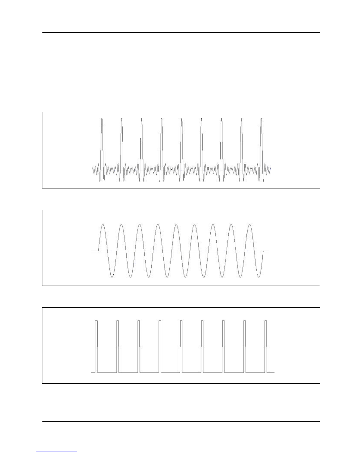
of time between linked or looped segments. Figure 1-5 shows an
example of a sequenced waveform. Assume the waveforms in
Figures 1-2 through 1-4 were placed in segments 1 through 3.
Figure 1-2, Segment 1 - Sin(x)/x Waveform
Figure 1-3, Segment 2 - Sine Waveform
Figure 1-4, Segment 3 - Pulse Waveform
Getting Started 1-9

3151 And 3151A User Manual
The following sequence was made of segment 2 repeated twice,
segment 3 repeated once and segment 1 repeated four times.
Figure 1-5, Sequenced Waveforms
Output State
Synchronization
Filter
The main output can be turned on or off. The internal circuit is
disconnected from the output BNC connector by a mechanical switch
(relay). This feature is useful for connecting the Model 3151/3151A
main output, along with other instruments, to an analog bus. For
safety reasons, after power on, the main output is always off.
Multiple Model 3151/3151As may be synchronized and operated
together inside one VXIbus chassis. With one instrument configured
as master and the rest of the instruments configured as slaves, the
instruments are phase-locked to the start phase on the master
module. The slave modules may be configured to have phase offsets
within the range of 0B to 360B. There is no need to install multiple
Model 3151/3151A modules in adjacent slots to be able to phase
synchronize modules.
Three filters are built into the Model 3151/3151A, each having a
different cutoff frequency and rise time properties. These filters are
available for use in various applications, depending on the specific
application. The 20 MHz Gaussian filter has a gaussian response
which smooths fast transitions and eliminates ringing and
aberrations. The 25 MHz and the 50 MHz filters are elliptical with a
very sharp cutoff frequency. They are useful for removing the
staircase effect from waveforms that are generated with high
frequency clock rates.
Getting Started 1-10

3151 And 3151A User Manual
Programming The
Front Panel
Indicators
Model 3151/3151A
There are three LED’s on the front panel. The FAIL LED (Red)
illuminates at power-up until the Model 3151/3151A has passed selftest. If the Model 3151/3151A self-test fails, the FAIL LED remains
illuminated. The FAIL LED may be illiminated during normal
operation if the Model 3151/3151A stops communication.
The ACCESS LED (Amber) iluminates each time a command has
been received by the Model 3151/3151A. This light remains on
during shared memory data transfer.
When the output state is on, the OUTPUT LED (Green) light
illuminates. It goes off when the output state is changed to off.
The Model 3151/3151A has no controls on the front panel.
Instrument functions, parameters, and modes can only be accessed
through VXIbus commands. There are a number of ways to talk to
the instrument. They all require that an appropriate software driver
be installed in the Resource Manager (slot 0). The rest is a matter of
practice and knowledge of the language in use. There are other
system considerations like address selection that have to be settled
before programming the instrument. These topics are discussed in
later chapters.
Low level programming of the Model 3151/3151A is done using SCPI
(Standard Commands For Programmable Instruments) language.
Programming aspects are covered in Chapters 3 and 4.
High level drivers like VXIplug&play and WaveCAD are beyond the
scope of this manual. Contact your Racal representative for more
information about high level drivers for the Model 3151/3151A.
Getting Started 1-11

This page was left intentionally blank.
3151 And 3151A User Manual
Getting Started 1-12

3151 And 3151A User Manual
Chapter 2
Configuring The Instrument
Installation
Overview
Unpacking and
Initial Inspection
Safety
Precautions
This chapter contains information and instructions necessary to
prepare the Model 3151/3151A for operation. Details are provided
for initial inspection, grounding safety requirements, repacking
instructions for storage or shipment, logical address selection and
installation information.
Unpacking and handling of the generator requires only normal
precautions and procedures applicable to handling of sensitive
electronic equipment. The contents of all shipping containers should
be checked for included accessories and certified against the
packing slip to determine that the shipment is complete.
The following safety precautions should be observed before using
this product and associated computer. Although some instruments
and accessories would normally be used with non-hazardous
voltages, there are situations where hazardous conditions may be
present.
This product is intended for use by qualified personnel who recognize
shock hazards and are familiar with the safety precautions required
to avoid possible injury. Read the operating information carefully
before using the product.
Exercise extreme caution when a shock hazard is present. Lethal
voltage may be present on cables, connector jacks, or test fixtures.
The American National Standard Institute (ANSI) states that a shock
hazard exists when voltage levels greater than 30V RMS, 42.4V peak
or 60 VDC are present.
Configuring The Instrument 2-1

3151 And 3151A User Manual
WARNING
For maximum safety, do not touch the product, test
cables, or any other instrument parts while power is
applied to the circuit under test. ALWAYS remove power
from the entire test system before connecting cables or
jumpers, installing or removing cards from the computer,
or making internal changes such as changing the
module address.
Do not touch any object that could provide a current path to the
common side of the circuit under test or power line (earth) ground.
Always keep your hands dry while handling the instrument.
When using test fixtures, keep the lid closed while power is applied
to the device under test. Safe operation requires that the computer lid
be closed at all times during operation. Carefully read the Safety
Precautions instructions that are supplied with your computer.
Performance
Checks
Grounding
Requirements
Before performing any maintenance, disconnect the line cord and all
test cables.
Maintenance should be performed by qualified service personnel
only.
The instrument has been inspected for mechanical and electrical
performance before shipment from the factory. It is free of physical
defects and in perfect electrical order. Check the instrument for
damage in transit and perform the electrical procedures outlined in
the section entitled Unpacking and Initial Inspection.
To insure the safety of operating personnel, the U.S. O.S.H.A.
(Occupational Safety and Health) requirement and good engineering
practice mandate that the instrument panel and enclosure be "earth"
grounded. Although BNC housings are isolated from the front panel,
the metal part is connected to earth ground.
Configuring The Instrument 2-2

3151 And 3151A User Manual
WARNING
Do not make an attempt to float the output from ground
as it may damage the Model 3151/3151A and your
equipment.
Long Term Storage
or Repackaging For
Shipment
If the instrument is to be stored for a long period of time or shipped
immediately, proceed as directed below. If you have any questions,
contact your local Racal Instruments Representative or the Racal
Instruments Customer Service Department.
1. Repack the instrument using the wrappings, packing material
and accessories originally shipped with the unit. If the original
container is not available, purchase replacement materials.
2. Be sure the carton is well-sealed with strong tape or metal
straps.
3. Mark the carton with the model and serial number. If it is to be
shipped, show sending and return address on two sides of the
box.
NOTE
If the instrument is to be shipped to Racal Instruments
for calibration or repair, attach a tag to the instrument
identifying the owner. Note the problem, symptoms, and
service or repair desired. Record the model and serial
number of the instrument. Show the work authorization
order as well as the date and method of shipment.
ALWAYS OBTAIN A RETURN AUTHORIZATION NUMBER
FROM THE FACTORY BEFORE SHIPPING THE
INSTRUMENT TO RACAL INSTRUMENTS.
Preparation For
Use
Preparation for use includes removing the Model 3151/3151A from
the container box, selecting the required logical address and
installing the module in a VXIbus chassis.
Configuring The Instrument 2-3

3151 And 3151A User Manual
Logical Address
Selection
The VXIbus Chassis Resource Manager identifies modules in the
system by the module’s address. VXIbus logical addresses can
range from 0 to 255, however, addresses 1 to 254 only are reserved
for VXIbus modules. Logical address 0 is reserved for the Resource
Manager. Logical address 255 permits the Resource Manager to
dynamically configure the module logical address.
To change the Model 3151/3151As logical address, use the 8position DIP switch accessible from the top side of the module near
the rear end of the case (switch S1). Figure 2-1 shows the location
of the logical address switch. The switches are marked with numbers
1 to 8. The Model 3151/3151A uses binary values (20 to 27) to set
the logical address using the active low address switch. A switch is
active when its arm is placed in the ON position.
Racal Instruments ships the Model 3151/3151A with logical address
2.
Configuring The Instrument 2-4

3151 And 3151A User Manual
Figure 2-1, Set The Logical Address
Configuring The Instrument 2-5

3151 And 3151A User Manual
Installation
The instrument can be installed in any slot except slot 0 in a VXIbus
mainframe. When inserting the instrument into the mainframe, it
should be gently rocked back and forth to seat the connectors into
the backplane receptacle. The ejectors will be at right angles to the
front panel when the instrument is properly seated into the
backplane. Use two captive screws above and below the ejectors to
secure the instrument into the chassis.
After installation, perform an initial checkout and operational
verification.
Configuring The Instrument 2-6

3151 And 3151A User Manual
Chapter 3
Using The Instrument
Overview
Output Termination
Input/Output
Protection
This chapter contains information about how to operate the Model
3151/3151A. Unlike bench-type instruments, the Model 3151/3151A
must be programmed to turn on functions, change parameters and
configure various operating modes. The instrument can be
programmed using a set of SCPI commands. A list of SCPI
commands that affect the Model 3151/3151A is given in Table 4-1.
The following paragraphs describe the various modes of operation
and give examples on how to program the Model 3151/3151A.
During use, output connectors must be properly terminated to
minimize signal reflection or power loss due to an impedance
mismatch. Proper termination is also required for an accurate
amplitude level at the main output connector. Use 50Ω cables and
terminate the main and SYNC cables with terminating resistors.
Always place the 50Ω termination at the far end of the cables.
The Model 3151/3151A provides protection for internal circuitry
connected to input and output connectors. Refer to the specifications
in Appendix A to determine the level of protection associated with
each input or output connector.
Power On/Reset
Defaults
At Power On or as a result of a software reset, the Model
3151/3151A defaults to the conditions shown in Table 3-1. A
complete list of all parameters and their default values is given in
Chapter 4.
Use the following command to place the instrument in its default
state:
RESet;
Using the IEEE-STD-488.2 common command *RST will have the
same result.
Using The Instrument 3-1

3151 And 3151A User Manual
Table 3-1, Default Conditions After Power On, RESet or *RST
Output State: Off Operating Mode: Continuous
Filter State: Off Filter Type: 20 MHz
ECLTRG0-1: Off TTLTRG0-7: Off
Output Trigger Source: BIT SYNC State: Off
Std. Wave Frequency: 1 MHz Arb. Wave Sample Clock:1 MHz
Amplitude: 5 V Offset: 0 V
Output Mode: Std. Waveforms Standard Waveform: Sine
Inter-module Phase Advance Mode: Auto
Synchronization State: Off SYNC Out Position: Point n-6
SYNC Slate: Off
Trigger Slope: Positive Internal Trigger Period: 100F Sec
Shared Memory State: Off Shared Memory Mode: Read
What To Do Now
When writing low level code to operate the Model 3151/3151A, follow
the instructions in this chapter to understand the meaning and
response that each command generates. Examples contained in the
following paragraphs show basic techniques on how to program
output waveforms.
Example 1
The following example programs the Model 3151/3151A to turn on
the main output, generate a square waveform, program the
frequency to 2 MHz, program the amplitude to 5 V and offset to 2.5
V.
/* Reset the Model 3151/3151A to its default condition as listed in
Table 3-1.*/
:RESet;
/* Change the output waveform to square. Note that there is no need
to use the FUNC:MODE command as the default value after RESet
is FIXed.*/
:FUNCtion:SHAPe SQUare;
/* Change the frequency to 2 MHz.*/
/*Change the amplitude to 5 V and the offset to 2.5 V.*/
Using The Instrument 3-2
:FREQuency 2e6;
:VOLTage 5;
:VOLTage: OFFSet 2.5;

3151 And 3151A User Manual
There are three offset windows ("8 V, "800 mV, "80 mV); the
window selected is a function of the amplitude setting. Table 3.2
shows the maximum offset available within each window.
Amplitude Window Maximum Offset
$1.6 V "8 V 0 to "7.19 V
$160 mV "800 mV 0 to 719 mV
$10 mV "80 mV 0 to 75 mV
Table 3-2, Amplitude and Offset Ranges
To calculate the maximum offset available for a partiular amplitude
setting, use the following inequality:
Using the APPLy
Command
amplitudeV
* V
+
* # 8 V * 800 mV * 80 mV
offset
2
Tip: If the desired amplitude/Offset setting cannot be obtained using
Standard Waveforms, try generating it as an Arbitrary Waveform
using WaveCAD.
/* Turn the main output on.*/
:OUTPut ON;
/*Turn the SYNC output on, if required.*/
:OUTPut:SYNC ON;
If the above commands are executed correctly, a square waveform
will be seen on your oscilloscope.
The APPLy command provides a high level method of programming
the generator. Selection can be made for function, frequency,
amplitude, offset and other parameters which are associated with the
selected function. For example, the following statement outputs a 2
Vp-p square wave at 1 MHz with a 0 V offset and 10% duty cycle
using APPLy:
APPL:SQU 1E6, 2, 0, 10
It is not necessary to enter every parameter with the APPLy
command. If only the frequency and offset need to be changed, omit
the other parameters while keeping the commas. The other
parameters will be set to the power-up default values:
Using The Instrument 3-3

3151 And 3151A User Manual
APPL:SQU 10E6,,1
Alternatively, if just the first parameters need to be changed, omit the
commas. The other parameters will be set to the power-up default
values:
APPL:SQU 4e6,2
Queries can also be made on all parameters associated with a
standard function using the APPL: <function_shape>? query. For
example, if the generator was programmed using the above
APPLy:SQU command, query the square wave parameters using the
following query:
APPL:SQU?
The generator returns a string that contains all the parameters
associated with the square function similar to the following string:
"1.000e+6,5,0,50".
The command:
APPLy:SINusoid {<frequency>,<amplitude>,<offset>,
<phase>,<power>}
programs the generator to output a sine waveform with frequency,
amplitude, offset, start phase and power parameters. Parameters are
not optional if the above APPLy command is used. Include all other
parameters in the command. The default settings for these functions
are: 1 MHz, 5 Vp-p, 0 V, 0 and 1.
The command:
APPLy:TRIangle {<frequency>,<amplitude>,<offset>,
<phase>,<power>}
programs the generator to output a triangle waveform with frequency,
amplitude, offset, start phase, and power parameters. The default
settings for these functions are: 1 MHz, 5 Vp-p, 0 V, 0 and 1.
The command:
APPLy:SQUare {<frequency>,<amplitude>,<offset>,
<duty_cycle>}
programs the generator to output a square waveform with frequency,
amplitude, offset and duty cycle parameters. The default settings for
these functions are: 1 MHz, 5 Vp-p, 0 V, and 50%.
The command:
APPLy:PULSe{<frequency>,<amplitude>,<offset>,
Using The Instrument 3-4

3151 And 3151A User Manual
<delay>,<high_time>,<rise_time>,<fall_time>}
programs the generator to output a pulse waveform with frequency,
amplitude, offset, delay, rise time, high time and fall time parameters.
The default settings for these functions are: 1 MHz, 5 Vp-p, 0 V, 0%,
10%, 10% and 10%.
The command:
APPLy:RAMP {<frequency>,<amplitude>,<offset>,
<delay>, <rise_time>,<fall_time>}
programs the generator to output a ramp waveform with frequency,
amplitude, offset, delay, rise time, and fall time parameters. The
default settings for these functions are: 1 MHz, 5 Vp-p, 0 V, 0%, 10%
and 10%.
The command:
APPLy:SINC {<frequency>,<amplitude>,<offset>,
<number_cycles>}
programs the generator to output a sine(x)/x waveform with
frequency, amplitude, offset, and number of cycles parameters. The
default settings for these functions are: 1 MHz, 5 Vp-p, 0 V and 10.
The command:
APPLy:EXPonential <frequency>,<amplitude>,<offset>,
<exponent>}
programs the generator to output an exponential waveform with
frequency, amplitude, offset, and exponent parameters. The default
settings for these functions are: 1 MHz, 5 Vp-p, 0 V and -10.
The command:
APPLy:GAUSsian {<frequency>,<amplitude>,<offset>,
<exponent>}
programs the generator to output a gaussian waveform with
frequency, amplitude, offset, and exponent parameters. The default
settings for these functions are: 1 MHz, 5 Vp-p, 0 V and 10.
The command:
APPLy:DC {<percent_amplitude>}
programs the generator to output a DC level. The DC level is set as a
percent of programmed amplitude. The default setting for this
function is 100%.
Using The Instrument 3-5

3151 And 3151A User Manual
The command:
APPLy:USER {<segment_number>,<sampling_clock>,
<amplitude>,<offset>}
programs the generator to output an arbitrary waveform. The
specified segment number must be loaded with an arbitrary
waveform before the generator can execute this command
successfully. This command lets you specify segment number,
sampling clock rate, amplitude and offset. The default settings for
these functions are: 1, 1 MHz, 5 Vp-p and 0 V.
The query:
APPLy:<function_shape>?
queries parameters associated with the specified function shape.
Returns a string of values depending on the parameters that are
available for the selected function shape.
The query:
APPLy?
queries parameters associated with the currently selected function
shape and returns a string of values depending on the parameters
available for the selected function shape. For example, if the
generator is programmed to output a ramp waveform, the APPL?
command returns: "1e+6, 5, 0 , 0, 10, 10, 10".
Example 2
The following example programs the Model 3151/3151A using the
APPLy command. This example turns on the main output, generates
a square waveform, programs frequency to 2 MHz, programs
amplitude to 5 V and offset to 2.5 V. It also changes the square wave
duty cycle parameter to 25%.
/* Reset the Model 3151/3151A to its default condition as listed in
Table 3-1.*/
:RESet;
/* Change the output waveform to square, frequency to 2 MHz,
amplitude to 5 V, offset to 2.5 V and duty cycle to 25%. Note that
there is no need to use the FUNC:MODE command because the
default value after RESet is FIXed.*/
/* Turn the main output on.*/
Using The Instrument 3-6
:APPLy:SQUare 2e6,5,2.5,25

3151 And 3151A User Manual
:OUTPut ON
/*Turn the SYNC output on, if required. */
:OUTPut:SYNC ON
If the above commands are executed correctly, a square waveform
will be seen on your oscilloscope.
Using The Instrument 3-7

3151 And 3151A User Manual
Output
Configuration
Commands
Selecting an Output
Function Type
The output configuration commands control the output function,
shape, frequency, amplitude, filter and state. Optional modes are
omitted from these commands.
Use the following command to select the output function type:
FUNCtion:MODE {FIXed | USER | SEQuence}
When "FIXed" is selected, the generator outputs the standard
waveform currently selected by the FUNC:SHAP command. When
"USER" is selected, the generator outputs the arbitrary waveform
currently selected by the TRAC:SEL command. When "SEQuence"
is selected, the generator outputs the sequence that is programmed
using the SEQ:DEF command.
The query:
FUNCtion:MODE?
queries the output function type and returns either FIX, USER or
SEQ.
Selecting a Standard
Function Shape
Use the following command to select a standard output function:
FUNCtion:SHAPe {SINusoid | TRIangle | SQUare |
PULSe| RAMP | SINC | EXPonential | GAUSsian | DC}
The selected waveform is output using the previously selected
frequency, amplitude, offset, and other relevant settings. The
standard waveform will be output only after the FUNC:MODE:FIX
command is selected.
The query:
FUNCtion:SHAPe?
queries the standard function shape and returns either SIN, TRI,
SQU, PULS, RAMP, SINC, EXP, GAUS or DC.
Using The Instrument 3-8

3151 And 3151A User Manual
Changing the
Frequency and
Sample Clock
Use the following command to change the frequency for standard
waveforms and sample clock for arbitrary waveforms:
FREQuency {<frequency> | MINimum | MAXimum}
MIN selects the lowest frequency allowed for the currently active
function. MAX selects the highest frequency allowed for the currently
active function. The default frequency setting is 1 MHz for all
functions.
The query:
FREQuency?
Queries the frequency setting for the standard function currently
active and returns a value in hertz.
The command:
FREQuency:RASTer {<frequency> | MINimum |
MAXimum}
sets the sample clock frequency for the user and sequenced
functions. MIN selects the lowest frequency allowed for the currently
active segment or sequence. MAX selects the highest frequency
allowed for the currently active segment or sequence. The default
sample clock frequency setting is 1 MHz for all functions.
Note that the output frequency depends on the number of points
specified in the waveform. The output frequency can be computed
using the following formula: Output Frequency = Sample Clock /
Number of points in the active segment.
The query:
FREQuency:RASTer?
queries the sample clock frequency setting for the arbitrary segment
or sequence currently active and returns a value in hertz.
Using The Instrument 3-9

3151 And 3151A User Manual
Selecting the
Sample Clock
Source
Programming the
Output Amplitude
and Offset
Use the following command to select the source for the sample clock
for the user and sequenced functions:
FREQuency:RASTer:SOURce {EXT | INT | ECLTRG0}
EXT selects an external clock source. The external source is applied
to the front panel CLOCK IN connector. INT selects the internally
synthesized clock generator. ECLTRG0 selects a sample clock that
is available on the backplane. Note that ECLTRG0 is always the
active sample clock source when the Model 3151/3151A is set to
operate in phase synchronization mode.
The query:
FREQuency:RASTer:SOURce?
queries the sampe clock source setting and returns EXT, INT or
ECLT.
Use the following command to program the peak-to-peak amplitude
for the generated waveform.
VOLTage {<amplitude>|MINimum|MAXimum}
MIN selects the smallest amplitude. MAX selects the largest
amplitude. The default amplitude is 5.00 V (into 50Ω).
The query:
VOLTage?
Queries the output amplitude for the currently selected function and
returns a value in volts.
The command:
VOLTage:OFFSet <offset>
sets the offset for the currently active function. The default offset is 0
V.
The query:
VOLTage:OFFSet?
queries the output offset for the currently selected function and
returns a value in volts.
Using The Instrument 3-10

3151 And 3151A User Manual
Selecting the Filter
Type
Before selecting the filter type, use the following command to activate
the filter:
OUTPut:FILTer { OFF | ON}
ON enables the filter that has been selected with the
OUTP:FILT:FREQ command. The default filter state setting is OFF.
The query:
OUTPut:FILTer?
queries the output filter state and returns "0" (OFF) or "1" (ON).
The command:
OUTPut:FILTer:FREQuency {<20MHz | 25MHz |
50MHz>}
sets the filter frequency for the currently active function. 20 MHz has
a Gaussian response, and the 25 MHz and the 50 MHz filters have
an Elliptical response. Note that the filters cannot be changed if the
generator is set to output sine waveform from its standard waveform
library. The filters will be activated only after the OUTP:FILT ON
command. The default filter setting is 20 MHz. Note also that 20
MHz, 25 MHz and 50 MHz designate filter types. These parameters
should be programmed as switches, not as values. The filter type
cannot be programmed using OUTP:FILT:FREQ 25e6 or
OUTP:FILT:FREQ 50e6 Hz.
The query:
OUTPut:FILTer:FREQuency?
queries the currently selected filter setting and returns 20 MHz, 25
MHz or 50 MHz.
Using The Instrument 3-11

3151 And 3151A User Manual
Activating the
Backplane ECLTRG
and TTLTRG
The Model 3151/3151A can transmit and receive signals on the
VXIbus ECLTRG and TTLTRG lines.
Use the following command to activate one of two backplane
ECLTRG lines:
OUTPut:ECLTrg<n> { OFF | ON}
<n> designates the activated trigger line; 0 and 1 are available. ON
enables the selected trigger line. The trigger source for this line can
be selected with the TRIG:SOUR command. The default ECLTrg<n>
state is OFF.
The query:
OUTPut:ECLTrg<n>?
queries the ECLTrg<n> state and returns "<n>,0" (OFF) or "<n>,1"
(ON).
Turning on ECLTRG0 causes the module sample clock signal to be
routed onto the VXI backplane. Other Model 3151/3151As may be
set up to receive this sample clock using the command
FREQ:RAST:SOURCE ECLTRG0 (See Selecting the Sample
Clock Source). ECLTRG1 should not be enabled onto the
backplane. Note that ECLTRG0 and ECLTRG1 are both used for
Inter-Module Synchronization.
Using The Instrument 3-12
The TTLTRG lines can be used to transmit and receive trigger
signals between the Model 3151/3151A and other VXIbus modules.
Use the following command to activate one of eight backplane
TTLTRG lines:
OUTPut:TTLTrg<n> { OFF | ON}
<n> designates the activated trigger line and 0 through 7 are
available. ON enables the selected trigger line. The trigger source for
this line can be selected with the TRIG:SOUR command. The default
TTLTrg<n> state setting is OFF.
The query:
OUTPut:TTLTrg<n>?
queries the TTLTRG<n> state and returns "<n>,0" (OFF) or "<n>,1"
(ON).

3151 And 3151A User Manual
Assigning the
Validating
Source
For TTLTRG
The TTLTRG signals, when enabled and placed on the backplane,
can be asserted with signals coming from a number of sources. Use
the following command to assign the signal source for the active
TTLTRG line:
OUTPut:TRIGger:SOURce {BIT | LCOMplete |
INTernal | EXTernal}
BIT Generates a trigger signal at any point in
the waveform. The trigger position within the
waveform can be programmed using the
OUTPUT:SYNC:POS:POIN command. This
command is used to set both the TRIGger point
and the SYNC point.
LCOMplete Generates a trigger signal in SEQuence
mode only once when the selected segment
appears for the first time.
INTernal Generates a trigger signal at intervals set by the
internal trigger generator .
EXTernal Generates a trigger signal every time a trigger is
applied to the front panel TRIG IN connector.
Enabling the Main
Output
The query:
OUTPut:TRIGger:SOURce?
queries the validating signal source for the backplane TTLTRG<n>
lines and returns BIT, LCOM, INT or EXT.
For safety reasons, the main output default setting is OFF. Disable or
enable the main output using the following command:
OUTPut {OFF | ON}
When the main output state is programmed to ON, the output
connector is connected to the output amplifier through a 50Ω resistor.
In the OFF position, the output connector is disconnected from the
output amplifier by means of a mechanical relay. Ensure that voltage
is not applied to the main output connector when the Model
3151/3151A output state is programmed to ON.
The query:
OUTPut?
queries the state of the main output and returns "0" (OFF) or "1"
Using The Instrument 3-13

(ON).
3151 And 3151A User Manual
Enabling the Sync
Output
Assigning the
Source For The
SYNC Output
For safety reasons, the SYNC output default setting is OFF. Disable
or enable the SYNC output using the following command:
OUTPut:SYNC {OFF | ON}
When the SYNC output state is programmed to ON, the SYNC
output connector generates signals which are triggered by signals
selected using the SYNC:SOUR command. In the OFF position, the
SYNC connector has no output. It is connected electrically to the
internal circuitry at all times. Ensure that voltage is not applied to the
SYNC at any time. The default SYNC position is the 6th point from
the end of the waveform. The position of the SYNC signal can be
programmed using the OUTPUT:SYNC:POS:POIN command.
The query:
OUTPut:SYNC?
queries the state of the SYNC OUTPUT and returns "0" (OFF) or "1"
(ON).
The SYNC output, when enabled, can be triggered by signals coming
from a number of sources. Use the following command to select the
source for validating the SYNC output:
OUTPut:SYNC:SOURce {BIT | LCOMplete | SSYNc |
HCLock}
Using The Instrument 3-14
BITGenerates a sync signal every time the segment is output
in User mode as well as in Sequenced mode.
The sync position along the waveform can be
programmed using the
OUTPUT:SYNC:POS:POIN command. POIN is
used to set both the TRIGger point and the
SYNC point. The BIT signal is recommended
for use in countinuous mode.
LCOMplete Generates a sync signal in SEQuence
mode only once when the selected segment
appears for the first time in the sequence. The
identity of the segment can be programmed
using the TRAC:SEL command. The sync
position along the selected waveform can be
programmed using the
OUTPUT:SYNC:POS:POIN command. The
LCOM signal is recommended for use in

3151 And 3151A User Manual
Sequence mode.
SSYNc Generates a sync signal at intervals that are
synchronized with the internal clock generator.
This option is useful to minimize jitter when
using an oscilloscope. The SSYNc signal is
recommended for use in Triggered mode.
HCLock Generates a trigger signal at intervals equal to half
of the period of the sample clock. This option is
useful for synchronizing two-point waveforms
on an oscilloscope (sine and square waveforms
above 10 MHz).
The query:
OUTPut:SYNC:SOURce?
queries the validating signal source for the SYNC output and returns
BIT, LCOM, SSYN or HCL.
Selecting the SYNC
Position
The SYNC output can be programmed to output the SYNC signal at
any point along the output waveform. This function is available in
USER or SEQ modes only. Use the following command to select the
SYNC output position:
OUTPut:SYNC:POSition:POINt <value>
The SYNC position can be selected from point 0 to the last point of
the active waveform. SYNC position has to be programmed for each
segment. The default SYNC position is 6 points from the end of the
segment.
The query:
OUTPut:SYNC:POSition:POINt?
queries the output SYNC position and returns an integer value.
Using The Instrument 3-15

3151 And 3151A User Manual
Using the Built-In
Standard
Waveforms
The Standard Waveform commands control the various parameters
of the active Standard Waveform. Standard waveform commands
operate in a similar fashion for each of the Standard Waveforms. To
simplify the description of this set of commands, only the standard
waveform commands for the PULSe function are described. Use the
same procedure to program parameters for the SINe, TRIangle,
RAMP, SQUare, SINC, GAUSsian, EXPonential and DC waveforms.
The number of points used to define each Standard Waveform
varies. For SINe and SQUare:
Freq # 200kHz Points = 500
Freq < 200kHz Points =
MHz100
Freq
Freq > 10MHz Points = 10
For RAMP, PULSE, GAUSSian and EXPonential:
Freq # 100kHz Points = 1000
Freq > 100kHz Points =
MHz100
Freq
For TRIangle and SINC:
Freq # 200kHz Points = 500
Freq > 200kHz Points =
MHz100
Freq
The equations used for generating EXPonential, GAUSian and SINC
functions are as follows:
Using The Instrument 3-16

3151 And 3151A User Manual
2
2
2
2
For Positive EXPonential:
m
A
A
[
+
- = F(m)
1]-
7.7t
e
Where A = Amplitude
m = Current point (I..N)
N = Total number of points
t = Time constant set by user
For Negative EXPonential:
A
m/t-
A. = F(m)
-
e
For GAUSsian:
A
2
2
-
t/m
A. = F(m)
e
-
For SINC:
m
).A
.Sine(2.
∏
∏
R
m
.2.
= F(m)
R
where R = (number of points per cycle)
cyc = Number of cycles of SINC
The standard waveform will be available at the output connector only
after the FUNC:MODE FIX command has been executed. Select the
FUNC:SHAP PULS command. Parameters for the PULSe function
shape can now be modified and will cause an effect on the output
waveform. Note that changes made to parameters for a specific
function do not have any effect on other functions.
N
cyc
The command:
Using The Instrument 3-17

3151 And 3151A User Manual
PULSe:DELay <value>
sets the pulse delay in percent of the pulse period. For example, if
the pulse period is 100 ms, 10% will delay the first transition of the
pulse by 10 ms. Delay is measured from trigger to the first turning
point.
The query:
PULSe:DELay?
queries the pulse delay setting and returns a value in percent.
The command:
PULSe:TRANsition <value>
sets the pulse rise time in percent of the pulse period. For example, if
the pulse period is 100 ms, 5% rise time equals 5 ms. Pulse rise time
is measured between the two turning points of the first transition.
The query:
PULSe:TRANsition?
queries the pulse rise time setting and returns a value in percent.
The command:
PULSe:WIDTh <value>
sets the pulse width in percent of the pulse period. For example, if
the pulse period is 100 ms, 20% pulse width equals 20 ms. Pulse
width is measured between the two turning points on the top of the
pulse.
The query:
PULSe:WIDTh?
queries the pulse width setting and returns a value in percent.
The command:
PULSe:TRANsition:TRAiling <value>
sets the pulse fall time in percent of the pulse period. For example, if
the pulse period is 100 ms, 15% fall time equals 15 ms. Pulse fall
time is measured between the two turning points of the second
transition.
The query:
Using The Instrument 3-18

3151 And 3151A User Manual
PULSe:TRANsition:TRAiling?
queries the pulse fall time setting and returns a value in percent.
Selecting an
Operating Mode
Triggered Mode
The Model 3151/3151A offers four operating modes: Continuous,
Triggered, Gated and Burst. The selected waveform is repeated
continuously when the instrument is set to operate in Continuous
mode. In this mode, the Model 3151/3151A does not require a trigger
source to stimulate its output cycles. The default operating mode of
the instrument is continuous.
Triggered, Gated, and Burst modes require an external signal to
initiate output cycles. Information on how to trigger, gate and output a
burst of waveforms is given in the following paragraphs.
In Triggered mode, the output remains at a certain DC level as long
as the TRIG IN signal from the front panel remains inactive. A TTL
signal is used to stimulate the TRIG input. The generator is sensitive
to either the rising edge or the falling edge. Each time a transition at
the trigger input occurs, the Model 3151/3151A generates one
complete output waveform. At the end of the output cycle, the output
resumes position at a DC level equal to the last point of the
waveform.
The Triggered mode operates on standard waveforms and arbitrary
waveforms. Observe the limitations of the trigger signal as listed in
the specification section of this manual. Note that for Standard
Waveforms, other than square wave, the Model 3151/3151A is
limited to signal frequencies of 10 MHz or less. To place the Model
3151/3151A in Triggered mode, use the following command:
Gated Mode
INITitiate:CONTinuous {OFF | ON}
OFF places the instrument in Triggered mode. ON restores
continuous operation.
The query:
INITitiate:CONTinuous?
queries the instrument operating mode parameter and returns "0"
(OFF) or "1" (ON).
The Model 3151/3151A can be set to operate in Gated mode only
after the INIT:CONT OFF command has been received. The output
Using The Instrument 3-19

3151 And 3151A User Manual
remains at a certain DC level as long as the TRIG IN signal from the
front panel remains inactive. A TTL level signal is used to stimulate
the TRIG input. The gating signal can be programmed to be either
active high or active low. Each time the proper level is present at the
trigger input connector, the Model 3151/3151A generates output
waveforms as long as the gate signal is present. When the gate
signal is de-asserted, the output completes the last cycle and
resumes position at a DC level equal to the last point of the
waveform.
Gated mode operates on standard waveforms, arbitrary waveforms,
and on sequences of waveforms. Observe the limitations of the
gating signal as listed in the specification section of this manual. To
place the Model 3151/3151A in Gated mode, use the following
commands:
INIT:CONT OFF
TRIGger:GATE {OFF | ON}
The default state for the Gated mode is OFF. Turning Gated mode
ON automatically turns Burst mode off.
Burst Mode
The query:
TRIGger:GATE?
queries the gate state and returns "0" (OFF) or "1" (ON).
Burst mode is very similar to Triggered mode with the exception that
only one trigger signal is needed to generate a counted number of
output waveforms. In Burst mode, the output remains at a certain DC
level as long as the TRIG IN signal from the front panel remains
inactive. A TTL signal is used to stimulate the TRIG input. The
generator is sensitive to either the rising edge or the falling edge.
Each time a transition at the trigger input occurs, the Model
3151/3151A generates a number of output cycles that have been
programmed in the burst count parameter. At the end of the burst,
the output resumes position at a DC level equal to the last point of
the waveform. The burst count is programmable from 1 to 106. The
default burst value is 1.
The Burst mode operates on standard waveforms and arbitrary
waveforms. Note that the Model 3151/3151A cannot operate in
Sequence and Burst modes simultanously. Observe the limitations of
the trigger signal as listed in the specification section of this manual.
To place the Model 3151/3151A in Burst mode, use the following
commands:
INITitiate:CONTinuous OFF
TRIGger:BURSt ON
Using The Instrument 3-20

3151 And 3151A User Manual
TRIGger:COUNt <counts>
INIT:CONT OFF places the Model 3151/3151A in a non-continuous
mode. TRIG:BURS ON turns the burst function on. The TRIG:COUN
specifies the number of waveforms output after a qualified trigger
signal. To ensure proper operation, enable Burst mode after setting
up the burst parameters. When Burst mode is enabled, previously
programmed Trigger or Gate modes turn off automatically.
The query:
TRIGger:BURSt?
queries the state off Burst mode and returns "0" (OFF) or "1" (ON).
The query:
TRIGger:COUNt?
queries the burst count and returns an integer.
Selecting the
Trigger Source
When an external source is not available, the operator has the option
to use either the built-in trigger generator or a TTLTRG<n> signal to
stimulate its output. Use the following command to select the trigger
source for the instrument:
TRIGger:SOURce:ADVance {EXTernal | INTernal | TTLTrg<n>}
EXT is the default trigger source for the Model 3151/3151A. Select
the TTLT<n> option with <n> ranging from 0 to 7 to use one of
the TTLTRG lines
available on the backplane. Select INT to use the internal trigger
generator. Remember to program the period of this generator (as
shown later).
The query:
TRIGger:SOURce:ADVance?
queries the trigger source and returns EXT, INT or TTLT<n>.
Using The Instrument 3-21

3151 And 3151A User Manual
Using the Internal
Trigger Generator
The internal trigger generator is a free-running generator which is
asynchronous with the main output generator. When the internal
trigger source is selected, the front panel TRIG IN signal is inactive.
The internal trigger generator is also available in Burst mode, but has
no effect in Gated mode. To use the internal trigger generator,
place the instrument in Triggerd mode, but select the internal trigger
generator as the trigger source. Then use the following command to
program an internal trigger period:
TRIGger:TIMer <value>
The period of the internal trigger generator can be programmed
from 60 µs to 1000 s. The default period is 100 µs. The internal
trigger generator is ignored when either an external or TTLT source
is enabled.The query:
TRIGger:TIMer?
queries the period of the internal trigger generator and returns a
value in seconds.
Using The Instrument 3-22

3151 And 3151A User Manual
Selecting the
Trigger Slope
Using the Soft
Trigger
The trigger slope command selects the sensitive edge of the trigger
signal that is applied to the TRIG IN connector. The Model
3151/3151A can be made sensitive to either positive or negative
transitions. Use the following command to select the edge sensitivity
for the trigger signal:
TRIGger:SLOPe {POSitive | NEGative}
Positive going transitions will trigger the Model 3151/3151A when the
POS option is selected. Negative transitions will trigger the Model
3151/3151A when the NEG option is selected. POS is the default
slope.
The query:
TRIGger:SLOPe?
queries the trigger slope and returns POS or NEG.
There are a number of commands that are available to trigger the
Model 3151/3151A. The soft trigger command is one of them. To
use the soft trigger command, place the instrument in the
TRIG:SOUR EXT mode. Soft trigger is ignored in the internal or
TTLTrg<n> modes. Use the following SCPI commands to trigger the
instrument:
TRIGger
The IEEE-STD-488.2 common command *TRG will have the same
effect. Use either software command to trigger the Model
3151/3151A in Trigger, Burst and Triggered Sequence Advance
modes.
Using The Instrument 3-23

3151 And 3151A User Manual
Generating
Arbitrary
Waveforms
What Are Arbitrary
Waveforms?
The Model 3151/3151A cannot generate arbitrary waveforms without
first loading them into memory. A description of the arbitrary
waveform function and an explanation on how to load waveforms into
memory is given in the following paragraphs.
Arbitrary waveforms are generated from digital data points which are
stored in memory. Each data point has vertical resolution of 12 bits
(4096 points), i.e., each sample is placed on the vertical axis with a
precision of 1/4096.
Arbitrary waveform memory has the capacity to store up to 512K of
horizontal data points (64K for the –001 version of the 3151). Each
horizontal point has a unique address - the first being 00000 and the
last 64435. In cases where smaller wavelengths are required, the
Model 3151/3151A's waveform memory can be divided into smaller
segments. Then it is possible to select which segment is sampled,
how many times and in what sequence.
When the instrument is programmed to output arbitrary waveforms, a
clock samples the data points (one at a time) from address 0 to the
last address. The rate at which each sample is replayed is defined by
the sample clock rate parameter. The Model 3151/3151A provides
programmable sample clock rates from 100 mHz to 100 MHz.
Arbitrary Memory
Management
Memory
Unlike the built-in standard waveforms, arbitrary waveforms must first
be loaded into the instrument's memory. Correct memory
management is required for best utilization of the arbitrary memory.
An explanation of how to manage the arbitrary waveform memory is
given in the following paragraphs.
The Model 3151A's arbitrary memory consists of a fixed length of
524288 words (65,536 for Model 3151-001 version). 1K is always
reserved for the built-in standard waveforms. The maximum size
arbitrary waveform that can be loaded into memory is 523288 points
long. It is not always necessary to use the complete length of this
memory. The memory can be partitioned into smaller segments and
different waveforms can be loaded into each segment. The memory
can be partitioned into 4096 segments, each having a unique length
and identity. Minimum segment length is 10 points. Information on
how to partition the memory is given in the following paragraphs.
Arbitrary memory can be divided into smaller segments; up to 4096
different arbitrary waveforms can be generated with the Model
Using The Instrument 3-24

3151 And 3151A User Manual
Management
Commands
3151/3151A. The length of each segment is left totally to the users
discretion. To partition the arbitrary waveform memory, use the
following command:
TRACe:DEFine <segment_number>,<length>
Note that numbers, not names, are assigned to segments that are
defined. Numbers can range from 1 through 4096. The order of
assignment is not important as long as the size of the segments,
having already been defined, is not changed. You cannot query the
TRAC:DEF command so you must keep good track if you intend to
partition the memory into many segments.
If a mistake is made and removal of one or more segments from the
active directory is needed, use the following command:
TRACe:DELete <n>
where <n> is the number of the segment to be removed from
memory. Note that if a segment is deleted, the memory portion that
belonged to this segment is no longer accessible. The next segment
that is defined will be placed after the last defined memory segment.
However, if the last segment is deleted, the next downloaded
segment will be written on top of the deleted one. There is danger
that by using the TRAC:DEL command often large portions of
memory will remain unused. It is, therefore, recommended to
periodically clear the entire memory and only reload waveforms that
will be used.
To partition the memory from the beginning, use the following
command:
TRACe:DELete: ALL
Using The Instrument 3-25

3151 And 3151A User Manual
CAUTION
This command will destroy waveforms that were
previously loaded into memory. After using this
command, waveform segments will line-up from address
0 upwards.
Loading Arbitrary
Waveforms
There are two ways to load waveforms into the Model 3151/3151A;
using a graphical user interface, i.e., WaveCAD, or low-level
programming. When using WaveCAD, disregard most of this chapter
as WaveCAD does the work for you. When writing your own code,
use the following commands to load data into a specific memory
segment.
First, define the work area. Define the segment number and its
associated length. Segment length must be an even number. For
example, to use segment number 8 and give it a length of 1000
points, use this command:
TRACe:DEFine 8,1000
Next, make segment 8 the active segment. The active segment must
be selected because as waveforms are loaded, the Model
3151/3151A must be notified as to where to place the data it
receives. Select the active segment using the following command:
TRACe:SELect 8
The next step is to transfer data to the active segment. Data is
loaded into the Model 3151/3151A using high-speed binary transfer.
A special command is defined by IEEE-STD-488.2 for this purpose.
High speed binary transfer allows any 8-bit bytes (including extended
ASCII code) to be transmitted in a message. This command is
particularly useful for sending large quantities of data. The Model
3151/3151A uses this command to receive waveforms from the
controller:
This command causes the transfer of 2000 bytes of data (1000)
points into the active memory segment. The ASCII "#" ($23) is the
start of the binary data block. "4" designates the number of digits that
follow. "2000" is the even number of bytes to follow. The generator
represents binary data as 12-bit integers which are sent as two bytes.
Therefore, the total number of bytes is always twice the number of
data points in the waveform. For example, 2000 bytes are required to
download a waveform with 1000 points. Bytes are sent in byte-high,
byte-low order. The FORM:SWAP command can be used to reverse
Using The Instrument 3-26
TRACe #42000<binary_block>
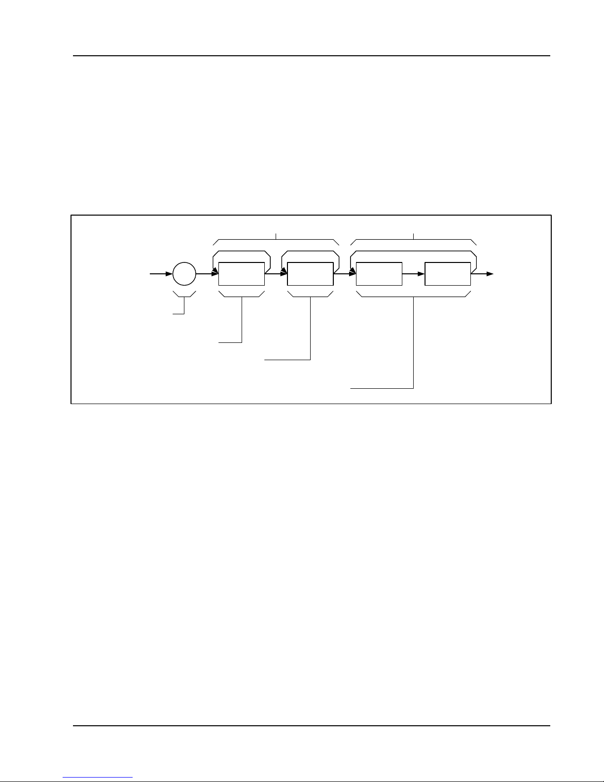
3151 And 3151A User Manual
this order.
When sending binary blocks to the Model 3151/3151A, the final byte
must be transmitted with the EOI bit set. Carriage Return and Line
Feed will not be detected as terminators. This permits the values
OD
and OA
HEX
to be used as data points.
HEX
The IEEE-STD-488.2 definition of Definite Length Arbitrary Block
Data Format is demonstrated in Figure 3-1.
Header section (ASCII) Binary section (binary)
Start of
Data Block
Number of Digits
to Follow in header
"#"
Byte Count: 2 x
Number of Points
non-zero
ASCII digit
ASCII digit
Waveform Data Point:
2 bytes
High Byte
(Binary)
Figure 3-1, Definite Length Arbitrary Block Data Format
6-bits of data are sent to the Model 3151/3151A although only 12 bits
are required to generate the waveform. The order of bytes and bits
and their values are shown in Figure 3-2.
Low Byte
(Binary)
Using The Instrument 3-27

3151 And 3151A User Manual
Figure 3-2, 12-Bit Waveform Data Format
Reversing Byte
Order
NOTE
The Model 3151/3151A operates in interlaced mode
where two memory cells generate one byte of data.
Segment size can be programmed in even-numbers only
and the generator can accept binary blocks of data that
are multiples of 4 only. For example, 2000 bytes will be
an acceptable binary block. 2002 is not a multiple of 4,
therefore, the generator will automatically adjust the size
to 1002 points and generate an error message.
Binary data is sent to the Model 3151/3151A in byte-high byte-low
order. This order can be reversed using the following command:
FORMat:BORDer {NORMal | SWAPped}
The default is NORM. This command is useful only for binary block
transfers.
The query:
FORMat:BORDer?
queries the byte order configuration and returns "NORM" or "SWAP".
Using Shared
Using The Instrument 3-28
Shared memory transfer is the fastest way to get waveforms into the

3151 And 3151A User Manual
Memory
Model 3151/3151A. In shared memory mode, the Model
3151/3151A's CPU disconnects from the waveform memory and
passes access to the VXIbus. The internal data bus is connected
directly to the VXIbus, and data is downloaded into the memory in
binary blocks using A24 memory space. Byte and bit order are the
same as with the Arbitrary Block transfers as shown in Figures 3-1
and 3-2. After the data is loaded into the Model 3151/3151A, control
is returned to the instrument.
In shared memory mode, the Model 3151/3151As memory acts
similar to Direct Memory Access (DMA). The instrument has to be
told when to receive data, send data, surrender control or gain
control. The Model 3151/3151A has an auto-increment address
counter. The Slot 0 Controller need only select the base address for
both write and read cycles. Shared Memory commands are
explained below.
To write to or read from a segment, the user must first define the
segment using the command TRACe:DEFine. The trace must then
be selected using the command TRACe:SELect. Refer to Loading
Arbitrary Waveforms for more information.
The command:
SMEMory:MODE {READ | WRITe}
sets the instrument to receive data from (WRITE) or send data
(READ) to the VXIbus.
The query:
SMEMory:MODE?
queries the shared memory mode and returns READ or WRITE.
The command:.
SMEMory:STATe {OFF | ON}
places the Model 3151/3151A in the shared memory state when ON
is selected. After this, the instrument cannot accept normal
commands. Data must be sent to the generator using shared
memory access. Normal command mode is resumed when the
SMEMory:STATe is changed to OFF.
The query:
SMEMory:STATe?
queries the shared memory state and returns "0" (OFF) or "1" (ON).
The following sequence should be used for shared memory
Using The Instrument 3-29

3151 And 3151A User Manual
transfers.
1. Slot 0 sends commands:
TRAC:DEF (n),(m) (Shared Memory write
only)
TRAC:SEL <n>
SMEM:MODE {READ * WRITE}
SMEM:STATE ON
2. Slot 0 repeatedly sends:
*OPC?
When response is 1, shared memory transfers may start.
3. Slot 0 sends command:
SMEM:STATE OFF
once data transfer is complete.
Sequence
The *OPC? Response is set to 1 when the Model 3151/3151A has
transferred memory access from the internal CPU to shared memory.
This typically takes a few milliseconds.
Sequenced waveforms are a means of adding more capability to the
generator. The Model 3151/3151A can link 4096 segments and loop
on each segment up to 106 times.
Using The Instrument 3-30

3151 And 3151A User Manual
Generating
Sequenced
Waveforms
What Are
Sequenced
Waveforms?
Sequenced waveforms are made of a number of arbitrary waveforms
which can be linked and repeated in various manners. Sequenced
waveforms are generated from waveforms stored in a library of
memory segments. Before using a sequence of waveforms, load
arbitrary memory with the required waveforms. Use TRAC# or shared
memory methods to load waveforms into memory. Information on
how to partition the memory and load waveforms is given in the
section entitled Generating Arbitrary Waveforms.
An example of how sequenced waveforms work is demonstrated in
the following figures. Figure 3-3 shows a sine(x)/x waveform that was
loaded into segment 1. Figure 3-4 shows a sine waveform that was
loaded into segment 2. Figure 3-5 shows a pulse waveform that was
loaded into segment 3.
The sequence generator lets you link segments in user-defined order
and repeat each segment as many times as needed.
Figure 3-3, Sin(x)/x Waveform Loaded Into Segment 1
Using The Instrument 3-31

3151 And 3151A User Manual
Figure 3-4, Sine Waveform Loaded Into Segment 2
Figure 3-5, Pulse Waveform Loaded Into Segment 3
Using The Instrument 3-32
Figure 3-6 shows a sequence of waveforms that were stored in three
different memory segments. Note that segment number 2 is
generated first and repeated twice, segment 3 follows once and then
segment 1 is repeated four times.

3151 And 3151A User Manual
Sequence
Commands
The following is an overview of how to define and program a
sequence of arbitrary waveforms.
Figure 3-6, Sequenced Waveforms - Continuous Advance Mode
A sequence is made of steps. A step can stand on its own or link to
another step. It is possible to have only one step in a sequence but
the output will look like a continuous waveform. If only one step is
specified and the Model 3151/3151A is placed in Triggered mode,
the output will behave, as it would in Burst mode where the repeat
number replaces the burst count parameter.
Aside from step numbers, each step has two other parameters:
segment number and repeat counter. The segment number specifies
which segment will be linked, and the repeat counter specifies how
many times the segment will repeat. Use the following command to
generate a sequence:
SEQuence:DEFine {<step_number>,<segment_number>,
<repeat>}
Using The Instrument 3-33

3151 And 3151A User Manual
NOTE:
In the Model 3151A the SEQ:DATA command may be
used in place of a series of SEQ:DEF commands if high
throughput is needed (see the next section)
Use this command up to 4095 times, each time for a different step
and for a different segment number and repeat combination. Note
that the same segment number can be used for different sequence
steps. The SEQ:DEF command does not change the FUNC:MODE
setting. Unless the FUNC:MODE SEQ command is used, the
SEQ:DEF command will have no immediate effect on the output
waveform or function.
The sequence generator goes through the steps in descending
order. In the continuous operating mode, the sequence is repeated
automatically after the last step has been completed. When the
generator is set to operate in Triggered mode, the output stops at the
last point of the last waveform in the sequence. In Gated mode, the
sequence is always completed after the gate stop signal.
If removal of a step from the sequence is required, use the following
command:
SEQuence:DELete <n>
where <n> is the step number to be removed from the sequence.
To delete all sequences, use the following command:
SEQuence:DELete:ALL
CAUTION
The above command will destroy sequences previously
loaded into memory.
Using The Instrument 3-34

3151 And 3151A User Manual
High Speed
Sequence
Downloads (3151A
Only)
Note: The high speed feature described in this section is not
available with the Model 3151, it is available for the 3151A only.
In cases where large numbers of sequence steps must be
downloaded to the 3151A (e.g., >50), for higher overall
throughput (e.g., 5x-10x improvement) it is recommended that
SEQ:DATA be used instead of a series of SEQ:DEF commands
(described in the above section). The SEQ:DATA command
takes the place of a series of SEQ:DEF commands by packing all
relevent data into a IEEE-STD-488.2 Definite Length Arbitrary
Block Data Format packet.
The format of the command is:
SEQuence:DATA#<header><binary data>
and the header structure is:
Nnnnn
where N = how many digits follow within the header and nnnn is
a decimal number (base 10) defining how many bytes of binary
data will follow. The header is formatted in ASCII numbers. The
number of bytes must be a multiple of 5. Each 5 bytes define one
step and its associated looping.
Header examples:
41000 (1000 bytes in binary format to follow)
510000 (10000 bytes in binary format to follow)
The byte structure of one 5-byte step (there can be up to 4096
steps) of the Binary Data section is:
2 bytes:
Segment #
3 bytes:
Number of Repeats
Using The Instrument 3-35
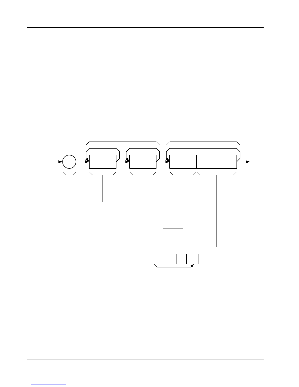
3151 And 3151A User Manual
The byte ordering of the Segment Number section is: High
byte, low byte. There is an offset between the Segment
Number above and the actual segment number. The above
structure ranges from 0 to 4095. The corresponding
segments are selected as ranging from 1 through 4096 with
the TRAC:SEL command.
The Repeat Number binary structure requires restructuring of
the byte order. The MSB (Most Significant Byte) of the 3
bytes is shifted around to the beginning and the mid-byte and
LSB (Least Significant Byte) are shifted left by one byte.
Header section (ASCII) Binary section (binary)
"#"
Start of
Data Block
Number of Digits
to Follow in header
non-zero
ASCII digit
Byte Count: 5 x Number
of Sequence Steps
Figure 3-7, Fast Sequence Download
ASCII digit
Segment Number for
this step: 2 bytes
Number of Repeats for
this step: 3 bytes
restructured as follows:
MSB
Binary Number
0-4095 range
Mid
Byte
Binary # of Repeats:
MSB shifted around to
LSB position
MSBLSB
Using The Instrument 3-36
A simple example using the sequence command is to generate a
1 step sequence with segment 1 repeated 74565 times:
SEQ:DATA#15<0000234501h>
where the 15 means:
1 specifies that one more byte will follow

3151 And 3151A User Manual
5 specifies that 5 binary bytes will follow
and the <0000230145h>:
74565 is 00012345h rearranged to be 234501
Four zeros (0000) for segment 1 (segment 0)
Putting these together gives 0000234501.
Triggered Sequence
Advance
Triggered Sequence Advance is a special case sequenced mode.
In Triggered Sequence Advance mode, the Model 3151/3151A idles
between steps until a valid trigger signal is sensed. The trigger
source can be selected from a number of options:
• An external trigger signal applied to the front panel TRIG IN
connector
• An internal trigger generator whose period is programmable
• VXIbus TTLTRG<n> triggers
• soft triggers.
A sequence operating in Continuous mode can be seen in Figure 3-
6. Figure 3-8 shows an example of the same sequence in Triggered
Sequence Advance mode.
Using The Instrument 3-37
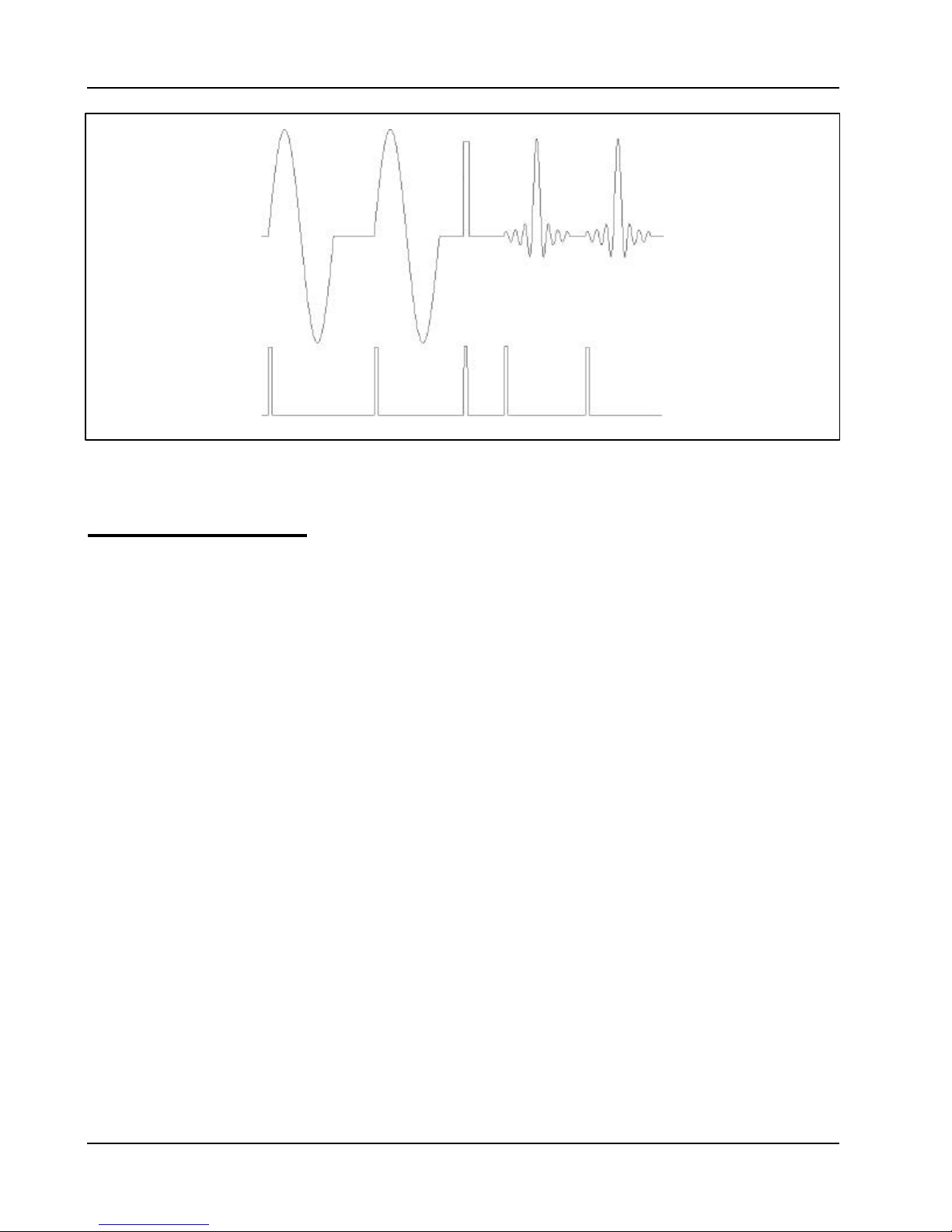
3151 And 3151A User Manual
Figure 3-8, Sequenced Waveforms - Triggered Advance Mode
Triggered Sequence
Advance Commands
Placing the Model 3151/3151A in Triggered Sequence Advance
mode is done in Triggered mode only. First, prepare the sequence of
waveforms using the commands that were explained before.
Second, place the instrument in Triggered mode using the
INIT:CONT OFF command. To place the Model 3151/3151A in
Triggered Sequence Advance mode, use the following command:
SEQuence:ADVance {AUTO | TRIGger}
AUTO specifies the normal continuous advance and TRIGger places
the instrument in Triggered Sequence Advance mode.
The query:
SEQuence:ADVance?
queries Triggered Sequence Advance mode and returns AUTO or
TRIG.
Using The Instrument 3-38

3151 And 3151A User Manual
Inter-Module
Synchronization
Synchronization
Although multiple Model 3151/3151As within one chassis run off a
common clock (CLK10), their outputs are not synchronized to each
other. If the same waveform length and clock rates for two modules
are selected and both are displayed on an oscilloscope, the outputs
may look as though they are synchronized even though they are not.
The waveforms may not start at the same point along the waveform.
If another waveform is selected or if the same waveforms are
reprogrammed, you may notice that the phase relationship between
the two modules has changed again.
CAUTION
Phase synchronization requires the use of the VXI
ECLTRG0 and ECLTRG1 signals. Other VXI instruments
must not drive ECLTRG0/1 while phase synchronization
is enabled.
There are phase synchronization commands that can tightly control
phase offsets between two or more Model 3151/3151As. These
commands are described below. To use the following commands,
two Model 3151/3151As are required. When synchronizing
modules, the waveforms in each module must have exactly the
same number of points.
First, load the waveforms in all the modules in preparation for phase
synchronization. Then select one Model 3151/3151A as master and
program it using the following commands:
PHASe:LOCK ON
PHASe:SOURce MAST
The above Model 3151/3151A is now programmed as master. Next,
program the other Model 3151/3151A modules as slaves (SLAVe)
and program their phase offset in relation to the master. As an
example, program the second and third Model 3151/3151A with 120
and 240 degrees offsets, respectively.
Use the following commands on the second Model 3151/3151A:
PHASe:SOURce SLAVe
PHASe:LOCK ON
Using The Instrument 3-39

3151 And 3151A User Manual
PHASe 120
Use the following commands on the third Model 3151/3151A:
PHASe:SOURce SLAVe
PHASe:LOCK ON
PHASe 240
The three Model 3151/3151A modules are now synchronized.
NOTE:
To insure jitter free synchronization, the sample clock
rate should not exceed 67MHz
The sample clock rate has no effect on phase offset accuracy.
However, when trying to synchronize modules that are programmed
to output waveforms with few memory points, a "1 count error
between modules may be seen. To remove this error, use the
following command:
PHASe:LOCK:NULL
CAUTION
The PHASe:NULL command toggles between removing
one count and adding one count. Therefore, if there was
no error, sending this command may add a 1 count error.
The query:
PHASe:LOCK?
queries the Phase Lock mode and returns "0" (OFF) or "1" (ON).
The query:
PHASe?
queries the phase offset and returns a value in degrees.
In query:
PHASe:SOUR?
queries the phase lock source and returns MAST or SLAV.
Using The Instrument 3-40

3151 And 3151A User Manual
Amplitude
Modulation
Commands
Arbitrary waveforms stored in memory segments are used as
modulating envelopes in Amplitude Modulation mode. The modulated
carrier is always a sine waveform with its frequency set in points. The
first step in modulating a waveform is to generate an arbitrary
waveform either from the standard function library or by downloading
a waveform from the controller.
The command:
AM <value>
sets the internal modulation depth in percent. Select values from 1%
to 200%. The default setting for AM depth is 50%.
The query:
AM?
queries the modulation depth and returns a value in percent.
The command:
AM:INTernal:FREQuency <value>
sets the frequency of the carrier sine waveform. The frequency of the
carrier wave is programmed in points. Select from 10 to 500 points.
The default setting for the carrier frequency is 100 points. The
frequency of the carrier wave can be computed from the sampling
clock frequency divided by the number of points in the active
segment. Use the FREQ:RAST? command to determine the current
sampling clock frequency. The maximum carrier frequency is the
sampling clock frequency divided by 10 points. The envelope
frequency should be less than the carrier frequency.
The query:
AM:INTernal:FREQuency?
queries the carrier frequency and returns a value in points.
The command:
AM:EXECute
enables amplitude modulation. To ensure proper operation, enable
the amplitude modulation after setting up the other modulation
parameters. Amplitude modulation cannot be turned on and off.
Therefore, ensure that the original arbitrary waveform is available in
another memory segment as a back-up.
Using The Instrument 3-41

3151 And 3151A User Manual
System-Related
Commands
System-related commands are used to place the instrument in a
known state, clear the instrument to its defaults, or to query the
generator for its errors or identity. The following is an overview of the
system-related commands.
The query:
SYSTem:ERRor?
reads one error from the error queue. A record of up to 30 errors can
be stored in the generator's error queue. Errors are retrieved in firstin-first-out (FIFO) order. The first error returned is the first error that
was stored. When all errors have been read from the queue, the
generator returns +0, "No error".
If more than 30 errors have occurred, the last error stored in the
queue (the most current error) is replaced with -350,"Too many
errors". No additional errors are stored until all errors have been
removed from the queue. The error queue is cleared only when
power is cycled off or after the execution of a *CLS command. The
*RST command does not clear the error queue.
The query:
SYST:ERR
queries the system error queue and returns a string with the following
format: -102,"Syntax error". A complete list of errors that can be
detected by the generator is given in Chapter 4.
The query:
SYSTem:VERSion?
queries the generator to determine the present SCPI revision and
returns a string similar to "1993.0"
The query:
*IDN?
reads the generator's identification string. The generator returns four
fields separated by commas. The first field is the manufacturer's
name, the second field is the model number, the third field is not
used (always "0") and the fourth field is the firmware version number.
The command returns "Racal Instruments, 3151A ,0,1.0".
The commands:
RESet
*RST
Using The Instrument 3-42

3151 And 3151A User Manual
reset the generator to its default state. The *RST and RES
commands have no effect on status registers, VXIbus states, VXI
address or SCPI command set.
The query:
*OPT?
returns 1 for the 3151A and the 3151-002 version, or 0 for the 3151-
001 version.
queries the waveform memory length installed in the 3151. The
response is 0 for 64K and 1" for 512K.
Using The Instrument 3-43

This page was left intentionally blank
3151 And 3151A User Manual
Using The Instrument 3-44

3151 And 3151A User Manual
Chapter 4
SCPI Command Reference
What’s In This
Chapter
Introduction To
SCPI Language
This chapter contains reference information for programming the
Model 3151/3151A. Standard Commands For Programmable
Instruments (SCPI) convention rules and syntax are explained in
detail. Table 4-1 lists all SCPI commands used for programming the
Model 3151/3151A. The command summary for each SCPI model is
also included in this chapter.
This chapter teaches you how to use SCPI commands to control
functions, modes, waveforms and other aspects of the instrument.
Prior understanding of SCPI programming is necessary for low level
programming of the Model 3151/3151A.
Commands to program the instrument over the MXI interface bus are
defined by the SCPI 1993.0 standard. The SCPI standard defines a
common language protocol. It goes one step further than IEEE-STD-
488.2 and defines a standard set of commands to control every
programmable aspect of the instrument. It also defines the format of
command parameters and the format of values returned by the
instrument.
SCPI is an ASCII-based instrument command language designed for
test and measurement instruments. SCPI commands are based on a
hierarchical structure known as a tree system. In this system,
associated commands are grouped together under a common mode
or root, thus forming subsystems. Throughout this manual, the
following conventions are used for SCPI command syntax.
Square Brackets ( [ ] ) Enclose optional keywords or parameters
Braces ( { } ) Enclose parameters within a command
string
Triangle Brackets ( < > ) Substitute a value for the enclosed
parameter
SCPI Command Reference 4-1

3151 And 3151A User Manual
Vertical Bar ( | ) Separate multiple parameter choices
Bold Typeface Letters Designate factory default values
Part of the OUTPut subsystem is shown below to illustrate the tree
system:
OUTPut
:FILTer
[:LPASs]
:FREQuency {20MHz|25MHz|50MHz}
[:STATe] OFF|ON
[:STATe] OFF|ON
OUTPut is the root keyword of the command; FILTer and STATe are
second level keywords. FREQuency and STATe are third level
keywords. A colon ( : ) separates a command keyword from a lower
level keyword.
Command Format
The format used to show commands in this manual is shown below:
FREQuency {<frequency>|MINimum|MAXimum}
The command syntax shows most commands (and some
parameters) as a mixture of upper and lower case letters. The upper
case letters indicate the abbreviated spelling for the command. For
shorter program lines, send the abbreviated form. For better program
readability, send the long form.
For example, in the above syntax statement, FREQ and
FREQUENCY are both acceptable forms. Use upper or lower case
letters. Therefore, FREQ, FREQUENCY, freq, and Freq are all
acceptable. Other forms such as FRE and FREQUEN will generate
an error.
The above syntax statement shows the frequency parameter
enclosed in triangular brackets. The brackets are not sent with the
command string. A value for the frequency parameter (such as
"FREQ 50e+6) must be specified.
Some parameters are enclosed in square brackets ([]). The brackets
indicate that the parameter is optional and can be omitted. The
brackets are not sent with the command string. If an optional
parameter is not specified, the generator uses a default value.
SCPI Command Reference 4-2

3151 And 3151A User Manual
Command Separator
A colon ( : ) is used to separate a command keyword from a lower
level keyword as shown below:
SOUR:FUNC:SHAP SIN
A semicolon ( ; ) is used to separate commands within the same
subsystem, and can also minimize typing. For example, sending the
following command string:
TRIG:SOUR:ADV INT;BURS ON;INT:RATE 5e-3
is the same as sending the following three commands:
TRIG:SOUR:ADV INT
TRIG:BURS ON
TRIG:INT:RATE 5e-3
Use the colon and semicolon to link commands from different
subsystems. For example, in the following command string, an error
is generated if both the colon and the semicolon are not used.
OUTP:STATE ON;:TRIG:STAT ON
The MIN and MAX
Parameters
Substitute MINimum or MAXimum in place of a parameter for some
commands. For example, consider the following command:
FREQuency {<frequency>|MINimum|MAXimum}
Instead of selecting a specific frequency, substitute MIN to set the
frequency to its minimum value or MAX to set the frequency to its
maximum value.
SCPI Command Reference 4-3

3151 And 3151A User Manual
Querying Parameter
Setting
Query Response
Format
SCPI Command
Terminator
Query the current value of most parameters by adding a question
mark ( ? ) to the command. For example, the following command
sets the output function to square:
SOUR:FUNC:SHAP SQR
Query the output function by executing:
SOUR:FUNC:SHAP?
The response to a query depends on the command sent to the
instrument to generate the query response. In general, a response to
a query contains current values or settings of the generator.
Commands that set values can be queried about their current value
of the setting. Commands that set modes of operation can be
queried about their current mode setting. IEEE-STD-488.2 common
queries generate responses which are common to all instruments
that are connected to the GPIB interface.
A command string sent to the function generator must terminate with
a <new line> character. The IEEE-STD-488 EOI (end-or-identify)
message is interpreted as a <new line> character. A <carriage
return> followed by a <new line> is also accepted. Command string
termination always resets the current SCPI command path to the root
level.
IEEE-STD-488.2
Common
Commands
SCPI Command Reference 4-4
The IEEE-STD-488.2 standard defines a set of common commands
that perform functions like reset, trigger and status operations.
Common commands begin with an asterisk ( * ), are four to five
characters in length, and may include one or more parameters. The
command keyword is separated from the first parameter by a blank
space. Use a semicolon ( ; ) to separate multiple commands as
shown below:
*RST; *STB?; *IDN?

3151 And 3151A User Manual
SCPI Parameter
Type
Numeric Parameters
Discrete Parameters
The SCPI language defines several different data formats to be used
in program messages and response messages.
Commands that require numeric parameters will accept all commonly
used decimal representations of numbers including optional signs,
decimal points, and scientific notation. Special values for numeric
parameters like MINimum and MAXimum are also accepted.
Engineering unit suffixes with numeric parameters (e.g., MHz or kHz)
can also be sent. If only specific numeric values are accepted, the
function generator will ignore values which are not accepted and will
generate an error message. The following command is an example
of a command that uses a numeric parameter:
VOLT:AMPL <amplitude>
Discrete parameters are used to program settings that have a limited
number of values (i.e., FIXed, USER and SEQuence). They have
short and long form command keywords. Upper and lower case
letters can be mixed. Query responses always return the short form
in all upper case letters. The following command uses discrete
parameters:
Boolean Parameters
SOUR:FUNC:MODE {FIXed | USER | SEQuence}
Boolean parameters represent a single binary condition that is either
true or false. The generator accepts "OFF" or "0" for a false
condition. The generator accepts "ON" or "1" for a true condition.
The instrument always returns "0" or "1" when a boolean setting is
queried. The following command uses a boolean parameter:
OUTP:FILT { OFF | ON }
The same command can also be written as follows:
OUTP:FILT {0 | 1 }
SCPI Command Reference 4-5

3151 And 3151A User Manual
Arbitrary Block
Parameters
SCPI Command
Summary
Arbitrary block parameters are used for loading waveforms into the
generator's memory. Depending on which option is installed, the
Model 3151/3151A can accept binary blocks up to 1046576 bytes.
The following command uses an arbitrary block parameter that is
loaded as binary data:
TRAC:DATA#564000<binary_block>
Table 4-1 summarizes the complete SCPI command tree available to
program the generator over the GPIB. Refer to earlier sections in this
manual for more complete details on each command.
SCPI Command Reference 4-6

3151 And 3151A User Manual
Table 4-1, VXIbus Model 3151/3151A SCPI Commands List Summary
Keyword Keyword Parameter Form (Default in Bold)Parameter Form (Default in Bold) SCPI 1993.0SCPI 1993.0 NotesNotes
:FORMat
:BORDer NORMalNORMal | SWAPped Confirmed
:OUTPut Confirmed
[:STATe] OFFOFF | ON Confirmed
:FILTer Confirmed
[:LPASs] Confirmed
:FREQuency 20MHz20MHz | 25MHz | 50MHz Confirmed
[:STATe] OFFOFF | ON Confirmed
:ECLTrg<n> Confirmed
[:STATe] OFFOFF | ON Confirmed
:TRIGger Not confirmed
:SOURce BITBIT | LCOMplete | INTernal | EXTernal Not confirmed
:TTLTrg<n> (0;0;7) Confirmed (default;min;max)
[:STATe] OFFOFF | ON Confirmed
:SYNC Not confirmed
:SOURce BITBIT | LCOMplete | SSYNc | HCLock Not confirmed
[:STATe] OFFOFF | ON Not confirmed SYNC output inactive
:POSition Not Confirmed
[:POINt] (n-6;2;64536) Not Confirmed Even number, 64k memory
[:POINt] (n-6;2;523288) Not Confirmed Even number, 512k memory
[:SOURce] Confirmed
:APPLy FREQ,AMPL,OFFS Not confirmed
:SINusoid FREQ,AMPL,OFFS,PHAS,POW Not confirmed
:TRIangle FREQ,AMPL,OFFS,PHAS,POW Not confirmed
:SQUare FREQ,AMPL,OFFS,DCYC Not confirmed
:PULSe FREQ,AMPL,OFFS,DEL,WIDT,LEAD,TRA Not confirmed
:RAMP FREQ,AMPL,OFFS,DEL,LEAD,TRA Not confirmed
:SINC FREQ,AMPL,OFFS,NCYC Not confirmed
:GAUSsian FREQ,AMPL,OFFS,EXP Not confirmed
:EXPonential FREQ,AMPL,OFFS,EXP Not confirmed
:DC DC_AMPL Not confirmed
:USER SEG<n>,SCLK,AMPL,OFFS Not confirmed
:FREQuency Confirmed
[:CW] (1E6;100E-6;50E6) | MINimum | MAXimum Confirmed
:RASTer (1E6;100E-3;100E6)| MINimum | MAXimum Not confirmed
:SOURce INTINT | EXT | ECLtrg0 Not Confirmed
:VOLTage Confirmed
[:LEVel] Confirmed
[:IMMediate] Confirmed
[:AMPLitude] (5.00;10E-3;16.0) Confirmed
:OFFSet (0;-7.19;+7.19) Confirmed
:FUNCtion Confirmed
:MODE FIXedFIXed | USER | SEQuence Confirmed
:SHAPe SINSIN | TRI | SQU | PULS | RAMP | SINC | GAUS | EXP | DC Confirmed
:SINusoid Not Confirmed
:PHASe (0;0;360) Not Confirmed
:POWer (1;1;9) Not Confirmed
:TRIangle Not Confirmed
:PHASe (0;0;360) Not Confirmed
:POWer (1;1;9) Not Confirmed
:SQUare Not Confirmed
:DCYCle (50;1;99) Not Confirmed
:PULSe Confirmed
:DELay (10;0;99.9) Confirmed
:WIDTh (10;0;99.9) Confirmed
:TRANsition Confirmed
[:LEADing] (10;0;99.9) Confirmed
:TRAiling (10;0;99.9) Confirmed
SCPI Command Reference 4-7

3151 And 3151A User Manual
Keyword Parameter Form (Default in Bold) SCPI 1993.0 Notes
:RAMP Not Confirmed
:DELay (10;0;99.9) Not Confirmed
:TRANsition Not Confirmed
[:LEADing] (10;0;99.9) Not Confirmed
:TRAiling (10;0;99.9) Not Confirmed
:SINC Not Confirmed
:NCYCle (10;4;100) Not Confirmed
:GAUSsian Not Confirmed
:EXPonent (10;1;200) Not Confirmed
:EXPonential Not Confirmed
:EXPonent (-10;-200;200) Not Confirmed
:DC Not Confirmed
[:VOLTage] Not Confirmed
[:IMMediate] Not Confirmed
[:AMPLitude] (100;-100;100) Not Confirmed
:AM Confirmed
[:DEPTh] (50;1;200) Confirmed
:INTernal Confirmed
:FREQuency (100;10;500) Confirmed
[:EXECute] Not confirmed
:PHASe Confirmed
:LOCK Not confirmed
[:STATe] OFFOFF | ON Not confirmed
:NULL Not confirmed
[:ADJust] (0;0;360) Confirmed
:SOURce MASTer | SLAVe Confirmed
:SEQuence Not Confirmed
:ADVance AUTOmaticAUTOmatic | TRIGgered Not Confirmed
:DATA #<header><binary-block> Not Confirmed 3151A Only (No 3151 support)
:DEFine (1;1;4096),(1;1;4096),(1;1;1E6) Not Confirmed Link # = segment, repeat
:DELete Not Confirmed
[:NAME] (1;1;4096) Not Confirmed
:ALL Not Confirmed
:RESet Confirmed
:SYSTem Confirmed
:ERRor? Confirmed
:VERSion? Confirmed
:TRACe #<header><binary block> Confirmed
[:DATA] #<header><binary block> Confirmed
:DEFine (1;1;4096),(10;10;64536) Confirmed Even number, 64k mem, 3151-001
Version
:DEFine (1;1;4096),(10;10;523288) Confirmed Even number, 512k memory
:DELete Confirmed
[:NAME] (1;1;4096) Confirmed
:ALL Confirmed
:SELect (1;1;4096) Confirmed
:INITiate Confirmed
[:IMMediately] Confirmed
:CONTinuous OFF | ONON Confirmed
:TRIGger Confirmed
:BURSt Not Confirmed
[:STATe] OFFOFF | ON Not Confirmed
:COUNt (1;1;1E6) Confirmed
:DELay (0;10;2E6) Confirmed Minimum setting 0 or 10, even number
:SOURce Not Confirmed
:ADVance EXTernalEXTernal | INTernal | TTLTrg<n> Not Confirmed
:GATE Not Confirmed
[:STATe] OFFOFF | ON | 0 | 1 Not Confirmed
:SLOPe POSitivePOSitive | NEGative Confirmed
:TIMer (100e-6;60e-6;1000) Confirmed
[:IMMediate] Confirmed
:SMEMory Not Confirmed
:MODE READREAD | WRITe Not Confirmed
[:STATe] OFFOFF | ON Not Confirmed
:TEST Confirmed
[:ALL]? Confirmed
SCPI Command Reference 4-8

3151 And 3151A User Manual
Common CommandsCommon Commands Parameter Form (Default in BoldParameter Form (Default in Bold)) IEEE-STD-488.2IEEE-STD-488.2
*CLS Confirmed
*ESE (0;0;255) Confirmed
*OPC Confirmed
*RST Confirmed
*SRE (0;0;255) Confirmed
*TRG Confirmed
*ESE? Confirmed
*ESR? Confirmed
*IDN? Confirmed
*OPC? Confirmed
*SRE? Confirmed
*STB? Confirmed
*TST? Confirmed
Output
Configuration
Command Summary
Output Configuration commands control the output function, shape,
frequency, amplitude, filter and state. Optional modes are omitted
from these commands. Factory defaults after *RST are shown in bold
typeface. Parameter low and high limits are given where applicable.
Use the Standard Waveform parameters as described in Using The
APPLy Command.
Commands and Parameters (Low Limit,High Limit,Default)
[SOURce:]
APPLy:SINusoid {<frequency>,[<amplitude>,[<offset>,[<phase>,[<power>]]]]}
APPLy:TRIangle {<frequency>,[<amplitude>,[<offset>,[<phase>,[<power>]]]]}
APPLy:SQUare {<frequency>,[<amplitude>,[<offset>,[<duty_cycle>]]]}
APPLy:PULSe {<frequency>,[<amplitude>,[<offset>,[<delay>,[<high_time>
,[<rise_time>,[<fall_time>]]]]]]}
APPLy:RAMP {<frequency>,[<amplitude>,[<offset>,[<delay>,[<rise_time>
,[<fall_time>]]]]]}
APPLy:SINC {<frequency>,[<amplitude>,[<offset>,[<number_cycles>]]]}
APPLy:EXPonential {<frequency>,[<amplitude>,[<offset>,[<exponent>]]]}
APPLy:GAUSsian {<frequency>,[<amplitude>,[<offset>,[<exponent>]]]}
APPLy:DC {<percent_amplitude>}
APPLy:USER {<segment_number>,[<sampling_clock>,[<amplitude>, [<offset>]]]}
APPLy:<function_shape>?
APPLy?
FUNCTion:MODE {FIXed | USER | SEQuence} (FIX)
FUNCTion:MODE?
FUNCtion:SHAPe {SINusoid | TRIangle | SQUare | PULSe | RAMP | SINC
EXPonential | GAUSsian | DC } (SIN)
FUNCtion:SHAPe?
FREQuency {<frequency> | MINimum | MAXimum} (100E-6,50E6,1E6)
FREQuency?
FREQuency:RASTer {<frequency> | MINimum | MAXimum} (100E-3,100E6,1E6)
FREQuency:RASTer?
FREQuency:RASter:SOURce {EXT | INT | ECLtrg0} (INT)
SCPI Command Reference 4-9

3151 And 3151A User Manual
FREQuency:RASTer:SOURce?
VOLTage {<amplitude>| MINimum | MAXimum} (10.0E-3,16.0,5.00)
VOLTage?
VOLTage:OFFSet <offset> (-7.19,7.19,0)
VOLTage:OFFSet?
OUTPut:
FILTer:FREQuency {20MHz | 25MHz | 50MHz} 20MHz
FILTer:FREQuency?
FILTer {OFF | ON} OFF
FILTer?
[STATe] {OFF | ON} OFF
[STATe] SOURce?
SYNC:SOURce {BIT | LCOMplete | SSYNc | HCLock} BIT
SYNC:POSition <value> (0,64K/512K,n-6)
SYNC:SOURce?
SYNC[:STATe] {OFF | ON} OFF
SYNC[:STATe]?
ECLTrg<n>{OFF | ON} OFF
TTLTrg<n>{OFF | ON} OFF
TRIGger:SOURce {BIT | LCOMplete | INTernal | External} BIT
SCPI Command Reference 4-10

3151 And 3151A User Manual
Standard Waveform
Command Summary
Command and Parameters Low Limit High Limit Default
[SOURce:]
SINusoid:PHASe <value> 0 360 0
SINusoid:PHASe?
SINusoid:POWer <value> 1 9 1
SINusoid:POWer?
TRIangle:PHASe <value> 0 360 0
TRIangle:PHASe?
TRIangle:POWer <value> 1 9 1
TRIangle:POWer?
SQUare:DCYCle <value> 1 99 50
SQUare:DCYCle?
PULSe:DELay <value> 0 99.9 10.0
PULSe:DELay?
PULSe:WIDTh <value> 0 99.9 10.0
PULSe:WIDTh?
PULSe:TRANsition <value> 0 99.9 10.0
PULSe:TRANsition?
PULSe:TRANsition:TRAiling <value> 0 99.9 10.0
PULSe:TRANsition:TRAiling?
RAMP:DELay <value> 0 99.9 10.0
RAMP:DELay?
RAMP:TRANsition <value> 0 99.9 10.0
RAMP:TRANsition?
RAMP:TRANsition:TRAiling <value> 0 99.9 10.0
RAMP:TRANsition:TRAiling?
SINC:NCYCle <value> 4 100 10
SINC:NCYCle?
GAUSsian:EXPonent <value> 1 200 10
GAUSsian:EXPonent?
EXPonential:EXPonent <value> -200 200 -10
EXPonential:EXPonent?
DC <%_amplitude> -100 100 100
DC?
The Standard Waveform Commands control the various parameters
of the standard output functions. Optional modes are omitted from
these commands. Factory defaults after *RST are shown in bold
typeface. Parameter low and high limits are given where applicable.
The Standard Waveforms parameters could be used for the APPLy
command.
SCPI Command Reference 4-11

3151 And 3151A User Manual
Arbitrary Waveform,
Sequence, and
Shared Memory
Command Summary
Command and Parameters
TRACe #<header><binary_block>
TRACe:DEFine {<segment_number>, <length>}
TRACe:DELete <segment_number>
TRACe:DELete:ALL
TRACe:SELect <segment_number>
FORMat:BORDer {NORMal | SWAPped}
FORMat:BORDer?
SEQuence:DATA #<header><binary-block> NOTE: 3151A Only
SEQuence:DEFine <step_number>, <segment_number>, <#_repeat>
SEQuence:DELete <sequence_number>
SEQuence:DELete:ALL
SEQuence:SELect <sequence_number>
Arbitrary Waveform commands allow the definition of segments and
their corresponding lengths, addition and deletion of segments, and
the loading waveform data. Sequence commands control which
segments are linked and the number of times each segment is
repeated. The shared memory commands place the Model
3151/3151A in a special data transfer mode where the Model
3151/3151A's message-based interface is bypassed and data is
loaded directly from the VXIbus. Optional modes are omitted from
these commands. Defaults are shown in bold.
SMEMory:MODE {READ | WRITe}
SMEMory {OFF | ON}
Modulation
Command Summary
Command and Parameters Low Limit High Limit Default
[SOURce:]
AM <value> 0 200 50
AM?
AM:INTernal:FREQuency <value> 10 500 100
AM:INTernal:FREQuency?
AM:EXECute
The Modulation Commands controls amplitude modulation
parameters. Optional modes are omitted from these commands.
Factory defaults after *RST are shown in bold typeface. Parameter
low and high limits are given where applicable.
SCPI Command Reference 4-12

3151 And 3151A User Manual
Trigger Command
Summary
Command and Parameters Low Limit High Limit Default
INITiate:CONTinuous {OFF | ON} ON
TRIGger:BURSt {OFF | ON} OFF
TRIGger:COUNt <value> 1 1e6 1
TRIGger:DELay <value> 0/10 2e6 0
TRIGger:GATE {OFF | ON} OFF
TRIGger:SLOPe {POSitive | NEGative} POS
TRIGger:SOURce:ADVance {EXTernal | INTernal | TTLTrg<n>} EXT
TRIGger:TIMer: <value> 60e-6 1000 100e-6
TRIGger:IMMediate
*TRG
The Trigger commands control the trigger modes of the Model
3151/3151A. The Model 3151/3151A can be placed in Triggered,
Gated or Burst mode. Trigger source is selectable from an external
source, internal trigger generator, backplane TTLTrg 0-7, and
software trigger. Optional modes are omitted from these commands.
Factory defaults after *RST are shown in bold typeface. Parameter
low and high limits are given where applicable.
Inter-Module Phase
Synchronization
Command Summary
Command and Parameters Low Limit High Limit Default
PHASe:LOCK {OFF | ON} OFF
PHASe <value> 0
PHASe:SOURce {MASTer | SLAVe} SLAV
PHASe:NULL
Phase Synchronization commands control the phase offset between
two or more modules. There is no limit on how many modules can be
synchronized, as long as one module is programmed to be master
and the rest of the modules are slaves. The location of the slave
modules in relation to the master module does not affect the
accuracy of the phase offset.
The commands are presented exactly as they should be typed in
your program. Optional nodes were omitted from these commands.
Factory defaults after *RST or front panel reset are shown in bold
typeface. Parameter low and high limits are given where applicable.
o
360o (*) 0
o
SCPI Command Reference 4-13

3151 And 3151A User Manual
(*) High phase offset limit is not always 360o. It depends on the
number of points that were assigned to the active memory segment.
Phase offset limits are specified in Appendix A.
System-Related
Command Summary
IEEE-STD-488.2
Common
Commands and
Queries
The system-related commands are not related directly to waveform
generation but are an important part of operating the Model
3151/3151A. These commands can reset or test the instrument, or
query the instrument for system information.
Command and Parameters
SYSTem:ERRor?
SYSTem:VERSion?
RESet
*RST
TEST?
*TST?
*IDN?
*OPT?
Since most instruments and devices in an ATE system use similar
commands which perform similar functions, the IEEE-STD-488.2
document has specified a common set of commands and queries
which all compatible devices must use. This avoids situations where
devices from various manufacturers use different sets of commands
to enable functions and report status. The IEEE-STD-488.2 treats
common commands and queries as device dependent commands.
For example, *TRG is sent over the bus to trigger the instrument.
Some common commands and queries are optional, but most of
them are mandatory.
The following is a complete listing of all common commands and
queries which are used in the Model 3151/3151A.
*CLS - Clear the Status Byte summary register and all event
registers.
*ESE <enable_value> - Enable bits in the Standard Event enable
register. The selected bits are then reported to the status byte.
*ESE? - Query the Standard Event enable register. The generator
returns a decimal value which corresponds to the binary-weighted
sum of all bits set in the register.
*ESR? - Query the Standard Event register. The generator returns a
decimal value which corresponds to the binary-weighted sum of all
SCPI Command Reference 4-14

3151 And 3151A User Manual
bits set in the register.
*IDN? - Query the generators identity. The returned data is
organized into four fields, separated by commas. The generator
responds with its manufacturer and model number in the first two
fields, and may also report its serial number and options in fields
three and four. If the latter information is not available, the device
must return an ASCII 0 for each. For example, Model 3151/3151As
response to *IDN? is:
RACAL INSTRUMENTS, 3151A,0,1.0.
*OPC - Set the "operation complete" bit (bit 0) in the Standard Event
register after the previous commands have been executed.
*OPC? - Returns "1" to the output buffer after all the previous
commands have been executed. *OPC? is used for synchronization
between a controller and the instrument using the MAV bit in the
Status Byte or a read of the Output Queue. The *OPC? query does
not affect the OPC Event bit in the Standard Event Status Register
(ESR). Reading the response to the *OPC? query has the advantage
of removing the complication of dealing with service requests and
multiple polls to the instrument. However, both the system bus and
the controller handshake are in a temporary hold-off state while the
controller is waiting to read the *OPC? query response.
*OPT? - Returns a “1” for 3151A and 3151 512K version, and 0 for
Model 3151/3151A with 64k memory.
*RST - Resets the generator to its default state. Default values are
listed in Table 4-1.
*SRE <enable_value> - Enables bits in the Status Byte enable
register.
*SRE? - Query the Status Byte enable register. The generator
returns a decimal value in the range of 0 to 63 or 128 to 191 since bit
6 (RSQ) cannot be set. The binary-weighted sum of the number
represents the value of the bits of the Service Request enable
register.
*STB? - Query the Status Byte summary register. The *STB?
command is similar to a serial poll but is processed like any other
instrument command. The *STB? command returns the same result
as a serial poll, but the "request service" bit (bit 6) is not cleared if a
serial poll has occurred.
*TRG - Triggers the generator from the remote interface. This
command effects the generator if it is first placed in the Trigger or
Burst mode of operation and the trigger source is set to "BUS".
*TST? - Implements an internal self-test and returns a value as
SCPI Command Reference 4-15

3151 And 3151A User Manual
described below. Approximately 90% of the Model 3151/3151A
functionality is tested.
0 - Self-test passed
1 - DAC, DAC control, output amplifier or amplitude control
failure.
2 - Offset amplifier or offset control failure
4 - CPU to peripheral communication failure
8 - Trigger circuit or internal trigger failure
16 - Sequence or burst generator failure
32 - Clock generator failure
More than one failure can be reported at one time. For example, the
returned value 17" indicates both a DAC/Output Amplifier problem
and a sequence/burst generator problem exist.
*WAI - Wait for all pending operations to complete before executing
any addditional commands over the interface.
The SCPI Status
Registers
The Model 3151/3151A uses the Status Byte register group and the
Standard Event register group to record various instrument
conditions. Figure 4-1 shows the SCPI status system.
An Event Register is a read-only register that reports defined
conditions within the generator. Bits in an event register are latched.
When an event bit is set, subsequent state changes are ignored. Bits
in an event register are automatically cleared by a query of that
register or by sending the *CLS command. The *RST command or
device clear does not clear bits in an event register. Querying an
event register returns a decimal value which corresponds to the
binary-weighted sum of all bits set in the register.
An Event Register defines which bits in the corresponding event
register are logically ORed together to form a single summary bit.
The user can read from and write to an Enable Register. Querying an
Enable Register will not clear it. The *CLS command does not clear
Enable Registers but it does clear bits in the event registers. To
enable bits in an enable register, write a decimal value that
corresponds to the binary-weighted sum of the bits required to
enable in the register.
SCPI Command Reference 4-16
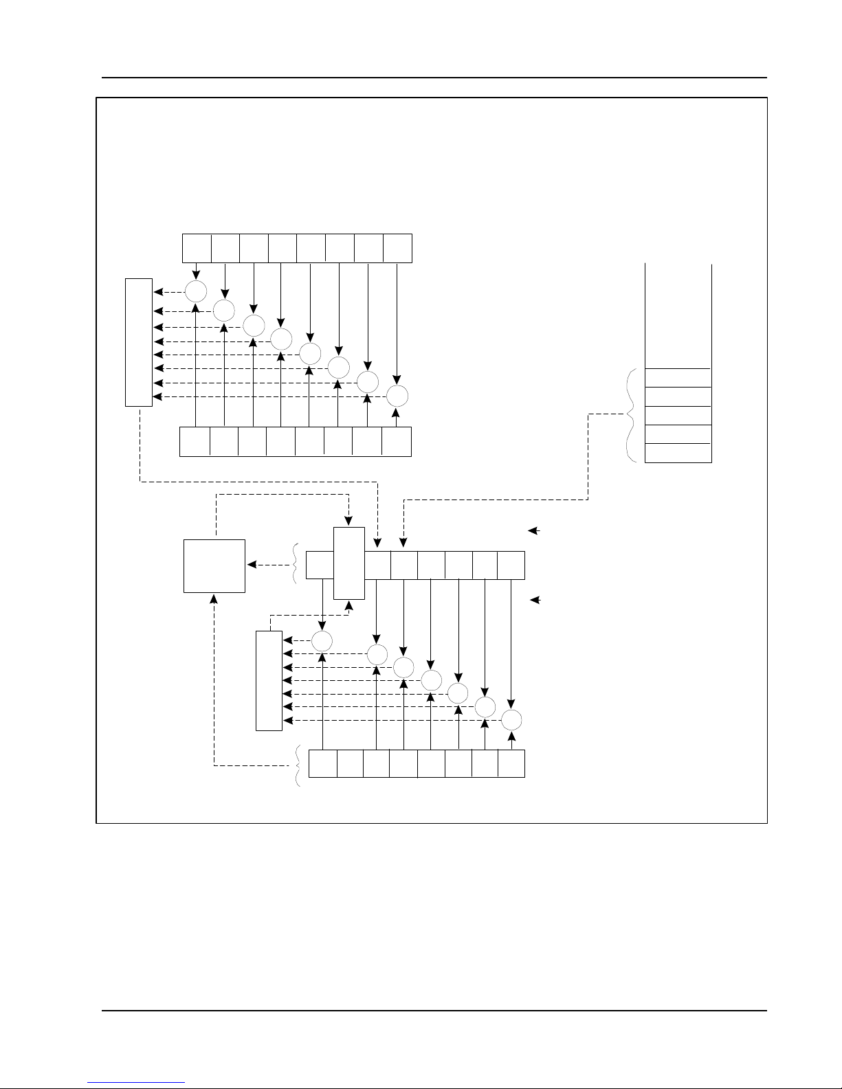
3151 And 3151A User Manual
&
&
&
&
&
&
&
&
&
&
&
&
&
5
4
3
2
1
0
5
4
3
2
1
0
Service Request
Enable Register
*SRE?
Status Byte Register
Output Queue
Event Status Enable
Device Dependent Error
Logical OR
Power On
User Request
Execution Error
Command Error
76
Query Error
Operation Complete
Request Control
Standard
Event StatusRegister
*ESR?
&
&
Queue
Standard
76
Service
Request
Generation
RQS
6
7
ESBMAV
MSS
Register
*ESE <value>
*ESE?
3 2 1
0
Not-Empty
read by Serial Port
read by *STB?
Logical OR
7
Figure 4-1, SCPI Status Registers
6
5 4 3
2
1 0
*SRE <value>
SCPI Command Reference 4-17

3151 And 3151A User Manual
The Status Byte
Register (STB)
The Status Byte summary register contains conditions from the other
registers. Query data waiting in the generator's output buffer is
immediately reported through the Message Available bit (bit 4). Bits
in the summary register are not latched. Clearing an event register
will clear the corresponding bits in the Status Byte summary register.
Description of the various bits within the Status Byte summary
register is given in the following:
Bit 0 - Decimal value 1. Not used, always set to 0.
Bit 1 - Decimal value 2. Not used, always set to 0.
Bit 2 - Decimal value 4. Not used, always set to 0.
Bit 3 - Decimal value 8. Not used, always set to 0.
Bit 4 - Decimal value 16. Message Available Queue Summary
Message (MAV). The state of this bit indicates whether or not the
output queue is empty. The MAV summary message is true when the
output queue is not empty. This message is used to synchronize
information exchange with the controller. The controller can, for
example, send a query command to the device and then wait for
MAV to become true. If an application program begins a read
operation of the output queue without first checking for MAV, all
system bus activity is held up until the device responds.
Bit 5 - Decimal value 32. Standard Event Status Bit (ESB) Summary
Message. This bit indicates whether or not one or more of the
enabled ESB events have occurred since the last reading or clearing
of the Standard Event Status Register.
Reading the Status
Byte
Register
Bit 6 - Decimal value 64. Master Summary Status (MSS)/Request
Service (RQS) Bit. This bit indicates if the device has at least one
condition to request service. The MSS bit is not part of the IEEESTD-488.1 status byte and will not be sent in response to a serial
poll. However, the RQS bit, if set, will be sent in response to a serial
poll.
Bit 7 - Decimal value 128. Not used, always set to 0.
The Status Byte summary register can be read with the *STB?
common query. The *STB? common query causes the generator to
send the contents of the Status Byte register and the MSS (Master
Summary Status) summary message as a single <NR1 Numeric
Response Message> element. The response represents the sum of
the binary-weighted values of the Status Byte Register. The *STB?
common query does not alter the status byte.
SCPI Command Reference 4-18

3151 And 3151A User Manual
Clearing the Status
Byte
Register
Service Request
Enable
Register
(SRE)
The entire Status Byte register can be cleared by removing the
reasons for service from Auxiliary Status registers. Sending the *CLS
command to the device after a SCPI command terminator and before
a Query clears the Standard Event Status Register and clears the
output queue of any unread messages. With the output queue
empty, the MAV summary message is set to FALSE. Methods of
clearing other auxiliary status registers are discussed in the following
paragraphs.
The Service Request enable register is an 8-bit register that enables
corresponding summary messages in the Status Byte Register.
Thus, the application programmer can select reasons for the
generator to issue a service request by altering the contents of the
Service Request Enable Register.
The Service Request Enable Register is read with the *SRE?
common query. The response to this query is a number that
represents the sum of the binary-weighted value of the Service
Request Enable Register. The value of the unused bit 6 is always
zero.
The Service Request Enable Register is written using the *SRE
command followed by a decimal value representing the bit values of
the Register. A bit value of 1 indicates an enabled condition.
Consequently, a bit value of zero indicates a disabled condition. The
Service Request Enable Register is cleared by sending *SRE0. The
generator always ignores the value of bit 6. Summary of *SRE
commands is given in the following.
*SRE0 - Clears all bits in the register.
*SRE1 - Not used.
*SRE2 - Not used.
*SRE4 - Not used.
*SRE8 - Not used.
*SRE16 - Service request on MAV.
*SRE32 - Service request on ESB summary bit.
*SRE128 - Not used.
SCPI Command Reference 4-19

3151 And 3151A User Manual
Standard Event
Status Register
(ESR)
The Standard Event Status Register reports status for special
applications. The 8 bits of the ESR have been defined by the IEEESTD-488.2 as specific conditions which can be monitored and
reported back to the user upon request. The Standard Event Status
Register is destructively read with the *ESR? common query. The
Standard Event Status Register is cleared with a *CLS common
command, with a power-on and when read by *ESR?.
The arrangement of the various bits within the register is firm and is
required by all GPIB instruments that implement the IEEE-STD-
488.2. Description of the various bits is given in the following:
Bit 0 - Operation Complete. Generated in response to the *OPC
command. It indicates that the device has completed all selected and
pending operations and is ready for a new command.
Bit 1 - Request Control. This bit operation is disabled on the Model
3151/3151A.
Bit 2 - Query Error. This bit indicates that an attempt is being made
to read data from the output queue when no output is either present
or pending.
Bit 3 - Device Dependent Error. This bit is set when an error in a
device function occurs. For example, the following command will
cause a DDE error:
VOLTage 7.25;:VOLTage:OFFSet 4.1
Both of the above parameters are legal and within the specified
limits, however, the generator is unable to generate such an
amplitude and offset combination.
Bit 4 - Execution Error. This bit is generated if the parameter
following the command is outside of the legal input range of the
generator.
Bit 5 - Command Error. This bit indicates the generator received a
command that was a syntax error or a command that the device does
not implement.
Bit 6 - User Request. This event bit indicates that one of a set of
local controls had been activated. This event bit occurs regardless of
the remote or local state of the device.
Bit 7 - Power On. This bit indicates that the device's power source
was cycled since the last time the register was read.
SCPI Command Reference 4-20

3151 And 3151A User Manual
Standard Event
Status Enable
Register (ESE)
The Standard Event Status Enable Register allows one or more
events in the Standard Event Status Register to be reflected in the
ESB summary message bit. The Standard Event Status Enable
Register is an 8-bit register that enables corresponding summary
messages in the Standard Event Status Register. Thus, the
application programmer can select reasons for the generator to issue
an ESB summary message bit by altering the contents of the ESE
Register.
The Standard Event Status Enable Register is read with the *ESE?
common query. The response to this query is a number that
represents the sum of the binary-weighted value of the Standard
Event Status Enable Register.
The Standard Event Status Enable Register is written using the *ESE
command followed by a decimal value representing the bit values of
the Register. A bit value one indicates an enabled condition.
Consequently, a bit value of zero indicates a disabled condition. The
Standard Event Status Enable Register is cleared by setting *ESE0.
Summary of *ESE messages is given in the following.
*ESE0 - No mask. Clears all bits in the register.
*ESE1 - ESB on Operation Complete.
*ESE2 - ESB on Request Control.
*ESE4 - ESB on Query Error.
*ESE8 - ESB on Device Dependent Error.
*ESE16 - ESB on Execution Error.
*ESE32 - ESB on Command Error.
*ESE64 - ESB on User Request.
*ESE128 - ESB Power on.
Error Messages
In general, whenever the Model 3151/3151A receives an invalid
SCPI command, it automatically generates an error. Errors are stored
in a special error queue and may be retrieved from this buffer one at
a time. Errors are retrieved in first-in-first-out (FIFO) order. The first
error returned is the first error that was stored. When you have read
all errors from the queue, the generator responds with a 0,"No error"
message.
If more than 30 errors have occurred, the last error stored in the
queue is replaced with -350, Too many errors". No additional errors
are stored until you remove errors from the queue. If no errors have
occurred when you read the error queue, the generator responds
with 0,"No error".
The error queue is cleared when power has been shut off or after a
*CLS command has been executed. The *RST command does not
clear the error queue. Use the following command to read the error
queue:
SCPI Command Reference 4-21

3151 And 3151A User Manual
SYSTem:ERRor?
Errors have the following format (the error string may contain up to
80 characters):
-102,"Syntax error"
A complete listing of the errors that can be detected by the generator
is given below.
-100,"Command error". When the generator cannot detect more
specific errors, this is the generic syntax error used.
-101,"Invalid Character". A syntactic element contains a character
which is invalid for that type.
-102,"Syntax error". Invalid syntax found in the command string.
-103,"Invalid separator". An invalid separator was found in the
command string. A comma may have been used instead of a colon
or a semicolon. In some cases where the generator cannot detect a
specific separator, it may return error -100 instead of this error.
-104,"Data type error". The parser recognized a data element
different than allowed.
-108,"Parameter not allowed". More parameters were received than
expected for the header.
-109,"Missing parameter". Too few parameters were received for the
command. One or more parameters that were required for the
command were omitted.
-128."Numeric data not allowed". A legal numeric data element was
received, but the instrument does not accept one in this position.
-131,"Invalid suffix". A suffix was incorrectly specified for a numeric
parameter. The suffix may have been misspelled.
-148,"Character data not allowed". A character data element was
encountered where prohibited by the instrument.
-200,"Execution error". This is the generic syntax error for the
instrument when it cannot detect more specific errors. Execution
error as defined in IEEE-488.2 has occurred.
-221,"Setting conflict". Two conflicting parameters were received
which cannot be executed without generating an error. An offset
value which is outside the amplitude level window may have been
sent.
-222,"Data out of range". Parameter data which followed a specific
SCPI Command Reference 4-22

3151 And 3151A User Manual
header could not be used because its value is outside the valid range
defined by the generator.
-224,"Illegal parameter value". A discrete parameter was received
which was not a valid choice for the command. An invalid parameter
choice may have been used.
-300,"Device-specific-error". This is the generic device-dependent
error for the instrument when it cannot detect more specific errors. A
device- specific error as defined in IEEE-488.2 has occurred.
-311,"Memory error". Indicates that an error was detected in the
instruments memory.
-350,"Too many errors". The error queue is full because more than
30 errors have occurred. No additional errors are stored until the
errors from the queue are removed. The error queue is cleared
when power has been shut off, or after a *CLS command has been
executed.
-410,"Query INTERRUPTED". A command was received which
sends data to the output buffer, but the output buffer contained data
from a previous command (the previous data is not overwritten). The
output buffer is cleared when power is shut off or after a device clear
has been executed.
Device-Specific
Commands
The Model 3151/3151A conforms to the 1993.0 version of the SCPI
standard. Some of the commands used are not included in the
1993.0 version. However, these commands are designed with the
SCPI standard in mind and they follow all of the command syntax
rules defined by the standard. Table 4-1 lists all device-specific
commands that were designed specifically for the Model 3151/3151A
as not confirmed SCPI 1993.0 commands.
SCPI Command Reference 4-23

This page was left intentionally blank.
3151 And 3151A User Manual
SCPI Command Reference 4-24

3151 And 3151A User Manual
Maintenance and Performance Checks
Chapter 5
What’s in This
Chapter
Disassembly
Instructions
This chapter provides maintenance, service information,
performance tests, and the information necessary to adjust and
troubleshoot the Model 3151/3151A Waveform Generator.
WARNING
The procedures described in this section are for use only
by qualified service personnel. Many of the steps
covered in this section may expose the individual to
potentially lethal voltages that could result in personal
injury or death if normal safety precautions are not
observed.
CAUTION
ALWAYS PERFORM DISASSEMBLY, REPAIR AND
CLEANING AT A STATIC SAFE WORKSTATION..
If it is necessary to troubleshoot the instrument or replace a
component, use the following procedure to remove the side panels:
1. Using a Phillips head screw driver, remove the two screws on
each side of the instrument, and one screw at the rear of the
instrument that secures the side panels.
2. Grasp one side panel and carefully slide and lift it off the
instrument. Use the same procedure to remove the other side
panel. After removing the side panels from the instrument,
access the component side for calibration and checks, and the
solder side when replacing components.
3. When replacing the side panels, reverse the above procedure.
Maintenance and Performance Checks 5-1

3151 And 3151A User Manual
Special Handling
Static Sensitive
Devices
MOS devices are designed to operate at very high impedance levels
of
for low power consumption. As a result, any normal static charge that
builds up on your person or clothing may be sufficient to destroy
these devices if they are not handled properly. When handling such
devices, use precaution to avoid damaging them as described below:
1. MOS IC’s should be transported and handled only in containers
specially designed to prevent static build-up. Typically, these
parts are received in static-protected containers of plastic or
foam. Keep these devices in their original containers until
ready for installation.
2. Ground yourself with a suitable wrist strap. Remove the devices
from the protective containers only at a properly grounded
work station.
3. Remove a device by grasping the body; do not touch the pins.
4. Any printed circuit board into which the device is to be inserted
must also be grounded to the bench or table.
5. Use only anti-static type solder suckers.
6. Use only grounded soldering irons.
Cleaning
7. Once the device is installed on the PC board, the device is
adequately protected and normal handling may resume.
The Model 3151/3151A should be cleaned as often as operating
conditions require. To clean the instrument, use the following
procedure:
1 Thoroughly clean the inside and outside of the instrument.
2 When cleaning inaccessible areas, remove dust with low pressure
compressed air or a vacuum cleaner.
3 Use alcohol applied with a cleaning brush to remove accumulation
of dirt or grease from connector contacts and component
terminals.
4 Clean the exterior of the instrument and the front panel with a mild
detergent mixed with water, applying the solution with a soft,
lint-free cloth.
Maintenance and Performance Checks 5-2
 Loading...