


Artisan Technology Group is your source for quality
new and certied-used/pre-owned equipment
• FAST SHIPPING AND
DELIVERY
• TENS OF THOUSANDS OF
IN-STOCK ITEMS
• EQUIPMENT DEMOS
• HUNDREDS OF
MANUFACTURERS
SUPPORTED
• LEASING/MONTHLY
RENTALS
• ITAR CERTIFIED
SECURE ASSET SOLUTIONS
SERVICE CENTER REPAIRS
Experienced engineers and technicians on staff
at our full-service, in-house repair center
Instra
Remotely inspect equipment before purchasing with
our interactive website at www.instraview.com
Contact us: (888) 88-SOURCE | sales@artisantg.com | www.artisantg.com
SM
REMOTE INSPECTION
View
WE BUY USED EQUIPMENT
Sell your excess, underutilized, and idle used equipment
We also offer credit for buy-backs and trade-ins
www.artisantg.com/WeBuyEquipment
LOOKING FOR MORE INFORMATION?
Visit us on the web at www.artisantg.com for more
information on price quotations, drivers, technical
specications, manuals, and documentation

1260 VXI
SWITCHING CARD
1260-38
MULTIPLEXER / SCANNER
PUBLICATION NO. 980673-037
RACAL INSTRUMENTS
Racal Instruments, Inc.
Tel: (800) RACAL-ATE, (800) 722-2528, (949) 859-8999; FAX: (949) 859-7139
4 Goodyear St., Irvine, CA 92618-2002
480 Bath Road, Slough, Berksh i re, SL1 6BE, United Kingdom
Tel: +44 (0) 1628 604455; FAX: +44 (0) 1628 662017
18 Avenue Dutartre, 78150 LeChesnay, France
Tel: +33 (1) 3923 2222; FAX: +33 (1) 3923 2225
Strada 2-Palazzo C4, 20090 Milanofiori Assago, Milan, Italy
Tel: +39 (0)2 5750 1796; FAX +39 (0)2 5750 1828
Technologiepark Bergisch Gladbac h, Friedrich-Ebert-Strasse, D-51429 Bergisch Gladbac h, Germany
Tel.: +49 2204 8442 00; FAX: +49 2204 8442 19
3 Powells Road, Brookvale, NSW 2100, Australia
Tel: +612 9936 7000, FAX: +612 9936 7036
26 Ayer Rajah Crescent, 04-06/07 Ayer Rajah I ndustrial Estate, Singapore 0513.
Unit 5, 25F., Mega Trade Center, No 1, Mei Wan Road, Tsuen Wan, Hong Kong, PRC
Tel: +852 2405 5500, FAX: +852 2416 4335
Racal Instruments, Ltd.
Racal Systems Electronique S.A.
Racal Systems Elettronica s.r.l.
Racal Elektronik System GmbH.
Racal Australia Pty. Ltd.
Racal Electronics Pte. Ltd.
Tel: +65 7792200, FAX: +65 7785400
Racal Instruments, Ltd.
http://www.racalinstruments.com
PUBLICATION DATE: March 2, 2001
Copyright 2001 by Racal Instruments, Inc. Printed in the United States of America. All rights reserved.
This book or parts thereof may not be reproduced in any form without written permission of the publisher.
Artisan Technology Group - Quality Instrumentation ... Guaranteed | (888) 88-SOURCE | www.artisantg.com

WARRANTY STATEMENT
All Racal Instruments, Inc. products are designed and manufactured to exacting standards and in full
conformance to Racal’s ISO 9001 procedures.
For the specific terms of your standard warranty, or optional extended warranty or service agreem ent, contact
your Racal customer service advisor. Please have the following information available to facilitate service.
1. Product serial number
2. Product model number
3. Your company and contact information
You may contact your customer service advisor by:
E-Mail: Helpdesk@racalinstruments.com
Telephone: +1 800 722 3262 (USA)
+44(0) 8706 080134 (UK)
+852 2405 5500 (Hong Kong)
Fax: +1 949 859 7309 (USA)
+44(0) 1628 662017 (UK)
+852 2416 4335 (Hong Kong)
RETURN of PRODUCT
Authorization is required from Racal Ins truments before you send us your product for service or calibration.
Call your nearest Racal Instruments suppor t facility. A list is located on the las t page of this m anual. If you are
unsure where to call, contact Racal Instrum ents, Inc. Custom er Support Depar tment in Ir vine, California, USA
at 1-800-722-3262 or 1-949-859-8999 or via fax at 1-949-859-7139. We can be reached at:
helpdesk@racalinstruments.com.
PROPRIETARY NOTICE
This document and the tec hnical data herein disclosed, are proprietary to Racal Instrum ents, and shall not,
without express written permission of Racal Instr um ents, be us ed, in whole or in part to s olicit quotations f rom
a competitive source or used for m anufacture by anyone other than Racal Instruments . The information herein
has been developed at private expense, and may only be used for operation and maintenance reference
purposes or for purposes of engineering evaluation and incor poration into technical specifications and other
documents which specify procurement of products from Racal Instruments.
Artisan Technology Group - Quality Instrumentation ... Guaranteed | (888) 88-SOURCE | www.artisantg.com

FOR YOUR SAFETY
Before undertaking any tr oubleshoot ing, maintenance or exploratory procedure, read carefully the
WARNINGS and CAUTION notices.
This equipment contains voltage hazardous to hum an life and safety, and is capable of inflicting
personal injury.
If this instrument is t o be powered from the AC line (mains) through an autotransform e r , ensur e the
common connector is connected to the neutral (earth pole) of the power supply.
Before operating the unit, ensure the conductor (green wire) is connected to the ground (earth)
conductor of the power outlet. Do not use a two-conductor extension cord or a three-prong/two-
prong adapter. This will defeat t he pr otective feature of the third conductor in the power cord.
Maintenance and calibration procedures sometimes call for operat ion of the unit with power applied
and protective covers removed. Read the procedures and heed warnings to avoid “live” circuit
points.
Before operating this inst r um ent:
1. Ensure the instrument is configured to operate on the voltage at the power source. See
Installation Section.
2. Ensure the proper fuse is in place for the power source to operate.
3. Ensure all other devices connected to or in proximity to this instrument are properly grounded or
connected to the protective third-wire earth gr ound.
If the instrument:
- fails to operate satisfactorily
- shows visible damage
- has been stored under unfavorable conditions
- has sustained stress
Do not operate until perform ance is checked by qualified personnel.
Artisan Technology Group - Quality Instrumentation ... Guaranteed | (888) 88-SOURCE | www.artisantg.com

This page was left intentionally blank.
Artisan Technology Group - Quality Instrumentation ... Guaranteed | (888) 88-SOURCE | www.artisantg.com

User Manual 1260-38
NOTE FOR SYSTEMS WITH 1260-OPT 01T
The “Module-Specific Syntax” section of this manual shows the command syntax for the
1260-01S Smart Card. If you are using the newer 1260-01T Smart Card, the commands
will NOT work as shown.
Consult the 1260-01T Manual for a description of the commands that may be used with the
1260-01T Smart Card.
The channel numbers described in this manual are valid for the 1260-01T. The channel
numbers continue to be used for the 1260-01T.
The syntax of the commands that use channel numbers has changed for those cards
controlled by the 1260-01T.
The new syntax used to close a channel is:
CLOSE (@ <module address> ( <channel> ) )
For example, with for a relay module whose <module address> is set to 7, closing
<channel> 0 is performed with the command:
CLOSE (@ 7 (0))
Using the older 1260-01S, the command would be (as shown in this manual):
CLOSE 7.0
Many other command syntax differences exist. Please consult chapter 2 of the 1260-01T
manual for a description of the commands which are available for the 1260-01T.
Addendum Page 6/98 1
Artisan Technology Group - Quality Instrumentation ... Guaranteed | (888) 88-SOURCE | www.artisantg.com
User Manual 1260-38
Control Information for the 1260-38A and 1260-38B
The following information describes the control-register-to-relay-channel mapping for a 1260-38A or 1260-38B
Relay Module. This information ma y be used to control the m odule when using a 1260-01T in the registerbased mode of operation.
Each channel on this module is contr oll ed b y setting or clear ing a singl e bit. C ontrol Regis ter s on the module
operate 8 channels simultaneous ly. There are eight control bits per Control Register . Setting the bit to a 1
closes the relay; setting the bit to a 0 opens the relay.
The table below shows th e mappin g bet ween logica l channels used t o operate the rela y module in mess agebased mode and the b its within the Control Regist ers that may be used to operate th e channel in registerbased mode.
Each Control Register is loc ated 2 addr esses f rom the pre vious Contr ol Register . This is sho wn in Tab le 2-2
of the 1260-01T manual. Control Register 0 is located at the “Base A24 Address” for the module. Consult the
“Register-Based Operation” Section of Chapter 2 of the 1260-01T manual for a description of calculating
control register addresses.
Note that when the 1260-01T message-based interface is used, ODD MUXes (channels 10 t hrough 17, 30
through 37, channels 50 through 57, …, 150 through 157) are operated in parallel with EVEN MUXes to
operate as a 4-wire MUX. That is, when cha nne l 0 is c lose d using the m ess age-based inter fac e with a 126038B, the firmware also closes chan nel 10; when ch annel 143 is op ened, the firm ware opens channe l 153 as
well.
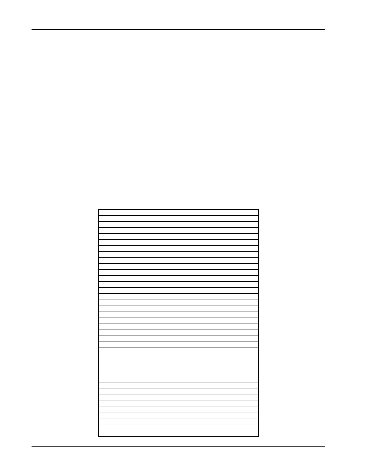
Channel Control Register Control Bit
000
101
202
303
404
505
606
707
10* 1 0
11* 1 1
12* 1 2
13* 1 3
14* 1 4
15* 1 5
16* 1 6
17* 1 7
20 2 0
21 2 1
22 2 2
23 2 3
24 2 4
25 2 5
26 2 6
27 2 7
30* 3 0
31* 3 1
32* 3 2
33* 3 3
34* 3 4
35* 3 5
36* 3 6
37* 3 7
40 4 0
41 4 1
42 4 2
43 4 3
44 4 4
2 Addendum Page 6/98
Artisan Technology Group - Quality Instrumentation ... Guaranteed | (888) 88-SOURCE | www.artisantg.com

User Manual 1260-38
Channel Control Register Control Bit
45 4 5
46 4 6
47 4 7
50* 5 0
51* 5 1
52* 5 2
53* 5 3
54* 5 4
55* 5 5
56* 5 6
57* 5 7
60 6 0
61 6 1
62 6 2
63 6 3
64 6 4
65 6 5
66 6 6
67 6 7
70* 7 0
71* 7 1
72* 7 2
73* 7 3
74* 7 4
75* 7 5
76* 7 6
77* 7 7
80 8 0
81 8 1
82 8 2
83 8 3
84 8 4
85 8 5
86 8 6
87 8 7
90* 9 0
91* 9 1
92* 9 2
93* 9 3
94* 9 4
95* 9 5
96* 9 6
97* 9 7
100 10 0
101 10 1
102 10 2
103 10 3
104 10 4
105 10 5
106 10 6
107 10 7
110* 11 0
111* 11 1
112* 11 2
113* 11 3
114* 11 4
115* 11 5
116* 11 6
117* 11 7
120 12 0
121 12 1
122 12 2
123 12 3
124 12 4
125 12 5
Addendum Page 6/98 3
Artisan Technology Group - Quality Instrumentation ... Guaranteed | (888) 88-SOURCE | www.artisantg.com

Channel Control Register Control Bit
126 12 6
127 12 7
130* 13 0
131* 13 1
132* 13 2
133* 13 3
134* 13 4
135* 13 5
136* 13 6
137* 13 7
140 14 0
141 14 1
142 14 2
143 14 3
144 14 4
145 14 5
146 14 6
147 14 7
150* 15 0
151* 15 1
152* 15 2
153* 15 3
154* 15 4
155* 15 5
156* 15 6
157* 15 7
1000 16 1
1001** 16 2
1002** 16 0
2000 16 5
2001** 16 6
2002** 16 4
3000 17 1
3001** 17 2
3002** 17 0
4000 17 5
4001** 17 6
4002** 17 4
5000 18 1
5001** 18 2
5002** 18 0
6000 18 5
6001** 18 6
6002** 18 5
7000 19 1
7001** 19 2
7002** 19 0
8002** 19 4
9000 16 3
9001 16 7
9002 17 3
9003 17 7
9004 18 3
9005 18 7
9006 19 3
9007 19 5
User Manual 1260-38
* This channel is operated automatically by the firmware for the 1260-38B when controlled using the
message-based int erface. This c hannel is NOT progr ammable when using the m essage-based interf ace for
the 1260-38B. This c hannel is set to the same state as the corresponding even MUX channel (e.g. when
channel 127 is closed, channel 137 is closed automatically by the firmware; when channel 24 is opened,
channel 34 is also opened by the firmware).
** This channel is not available when programming a 1260-38B in message-based mode.
4 Addendum Page 6/98
Artisan Technology Group - Quality Instrumentation ... Guaranteed | (888) 88-SOURCE | www.artisantg.com

User Manual 1260-38
Table of Contents
Chapter 1
MODULE SPECIFICATION..........................................................................................................1-1
Introduction ...............................................................................................................................1-1
1260-38 Module Specification...................................................................................................1-2
Ordering Information.................................................................................................................1-5
Safety........................................................................................................................................1-5
Product Support ........................................................................................................................1-5
Chapter 2
INSTALLATION INSTRUCTIONS.................................................................................................2-1
Unpacking and Inspection.........................................................................................................2-1
Reshipment Instructions............................................................................................................2-1
Option 01 Installation.................................................................................................................2-1
Module Installation.....................................................................................................................2-2
1260-38 ID Byte........................................................................................................................2-2
Chapter 3
MODULE OPERATION.................................................................................................................3-1
Module Configuration................................................................................................................3-1
Two-Wire Operation...............................................................................................................3-1
Four-Wire Operation..............................................................................................................3-1
One-Wire Operation...............................................................................................................3-1
100Ω Resistor Channels........................................................................................................3-3
Front Panel Connectors.........................................................................................................3-3
Mating Connectors.................................................................................................................3-3
1260-38 Module Specific Syntax ...............................................................................................3-4
Syntax....................................................................................................................................3-4
CLOSE Command..............................................................................................................3-5
OPEN Command................................................................................................................3-5
PDATAOUT Command ......................................................................................................3-5
PSETUP Command ...........................................................................................................3-6
Artisan Technology Group - Quality Instrumentation ... Guaranteed | (888) 88-SOURCE | www.artisantg.com
i

User Manual 1260-38
Chapter 4
DRAWINGS.................................................................................................................................. 4-1
Chapter 5
PARTS LIST.................................................................................................................................5-1
Chapter 6
OPTIONAL HARNESS ASSEMBLIES.......................................................................................... 6-1
Chapter 7
PRODUCT SUPPORT..................................................................................................................7-1
Product Support........................................................................................................................ 7-1
Reshipment Instructions............................................................................................................ 7-1
Support Offices.........................................................................................................................7-2
ii
Artisan Technology Group - Quality Instrumentation ... Guaranteed | (888) 88-SOURCE | www.artisantg.com

User Manual 1260-38
List of Figures
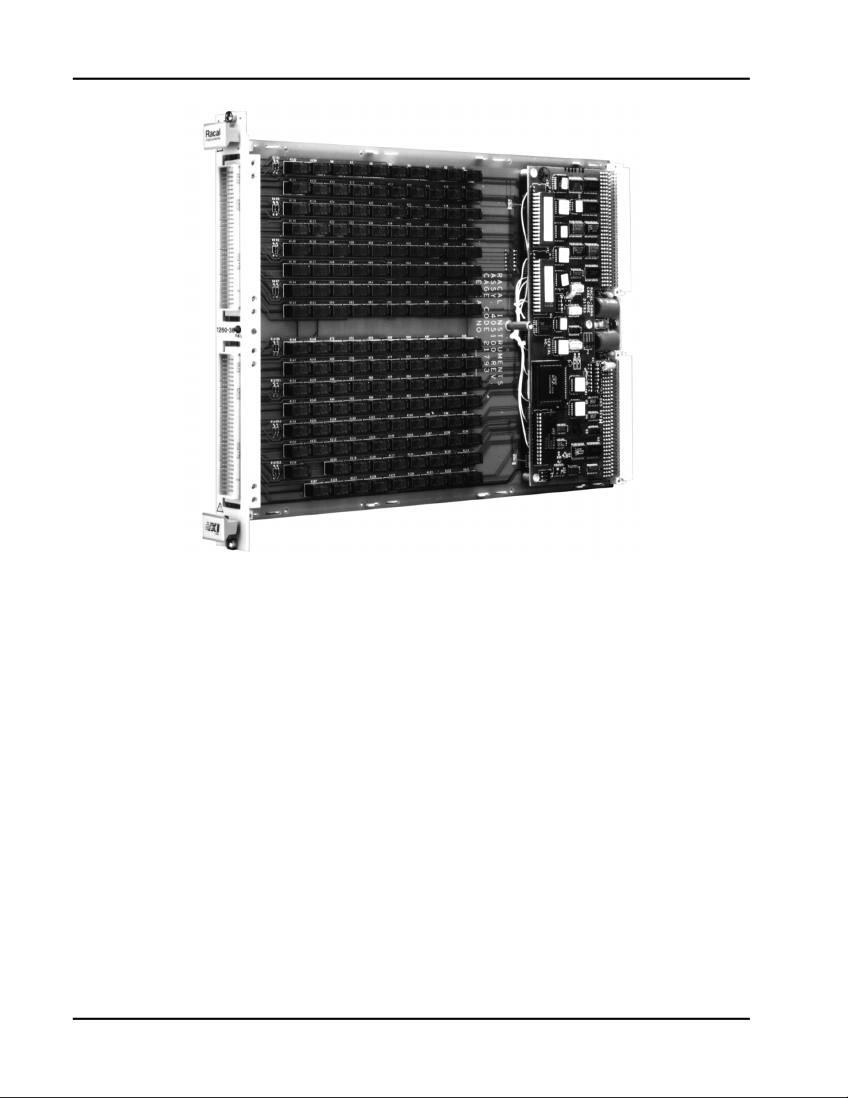
Figure 1-1, 1260-38 Multiplexer / Scanner....................................................................................1-2
Figure 3-1, 1260-38 Module Configuration Block Diagram............................................................3-7
Figure 3-2, 1260-38 Multiplexer Configuration Block Diagram......................................................3-8
Figure 3-2, 1260-38 Pin Connections, Front View.........................................................................3-9
Table 3-1, 1260-38 Channel Number/Connector Pin/Cable Mapping..........................................3-10
Artisan Technology Group - Quality Instrumentation ... Guaranteed | (888) 88-SOURCE | www.artisantg.com
iii

This page was left intentionally blank.
User Manual 1260-38
iv
Artisan Technology Group - Quality Instrumentation ... Guaranteed | (888) 88-SOURCE | www.artisantg.com

User Manual 1260-38
Chapter 1
MODULE SPECIFICATION
Introduction
The 1260-38 1 x 128 Two-Wire Scanner/Multiplexer Module
consists of eight pairs of 1 x 8 multiplexers. These eight pairs of
multiplexers, in conjunction with interconnecting relays, allow the
1260-38 module to be configured as:
- One 1 x 64 Four-wire multiplexer
- One 1 x 128 Two-wire multiplexer
- One 1 x 256 One-wire multiplexer
In addition, each pair of 1 x 8 multiplexers can be independently
configured as:
- Two 1 x 8 Two-wire multiplexers
- One 1 x 16 Two-wire multiplexer
- One 1 x 32 One-wire multiplexer
- One 1 x 8 Four-wire multiplexer
Figure 3-1, 1260-38 Module Configuration Block Diagram, and
Figure 3-2, 1260-38 Multiplexer Configuration Block Diagram,
shows a diagrammatic representation of the switch module and
multiplexer pair, respectively.
Module Specification 1-1
Artisan Technology Group - Quality Instrumentation ... Guaranteed | (888) 88-SOURCE | www.artisantg.com
User Manual 1260-38
1260-38 Module
Specification
Figure 1-1, 1260-38 Multiplexer / Scanner
Maximum Switch Power 125VA, 60W
Maximum Switch Voltage 25OVAC, 22OVDC
Maximum Switch Current 2A AC, 2A DC
Bandwidth (50Ω )
1 x 8 Configuration >30MHz
1 x 16 Configuration >30MHz
1 x 128 Configuration >2MHz
Insertion Loss (50Ω )
1 x 8 Configuration <0.10dB to 100kHz
<0.25dB to 1MHz
<1.70dB to 10MHz
Module Specification 1-2
Artisan Technology Group - Quality Instrumentation ... Guaranteed | (888) 88-SOURCE | www.artisantg.com

User Manual 1260-38
Insertion Loss (50Ω )
1 x 128 Configuration <0.20dB to 100kHz
<1.00dB to 1MHz
Crosstalk (50Ω )
I x 8 Configuration <-55dB to 100kHz
<-50dB to I MHz
<-22dB at 10MHz
Isolation (50Ω )
1 x 8 Configuration >40dB to 100kHz
>35dB to 1MHz
>20dB at 10MHZ
Path Resistance
1 x 8 Configuration <0.25Ω
1 x 128 Configuration <0.75Ω
Thermal EMF
1 x 8 Configuration <15µV
1 x 128 Configuration <20µV
Impedance
High-Low > 2000MΩ
High-Chassis > 2000MΩ
Low to Chassis > 2000MΩ
Capacitance
Channel to Chassis (1 x 8) <5pF
Channel to Chassis (1 x 128) <5pF
High to Low (1 x 8) <120pF
High to Low (1 x 128) <600pF
Temperature
Operating 0
Non-Operating 40
0
C to+550C
0
C to +710C
Relative Humidity 95+1-5% RH Non Condensing <30'C
75+1-5 %RH> 30
0
C
45+1-5 %RH > 40
Altitude
Module Specification 1-3
Artisan Technology Group - Quality Instrumentation ... Guaranteed | (888) 88-SOURCE | www.artisantg.com
0
C

User Manual 1260-38
Operating 10,000 ft
Non-Operating 15,000ft
Vibration 0.013" double amplitude,
5-55Hz
Shock, functional 30g, 11 msec, ½ sine wave
Bench Handling 4inch drop
Cooling Requirement
Without Option 01 installed
Airflow 1.0 liters/sec
Backpressure 0.05mm H
0
2
With Option 01 installed
Airflow 2.0 liters/sec
Backpressure 0.2mm H
0
2
Power Requirement
Without O ption 01 installed
+5V Static Current, I
+5V Dynamic Current, I
0.4A
pm
0.075A
dm
With Option 01 installed
+5V Static Current, I
+5V Dynamic Current, I
2.5A
pm
0.225A
dm
+24V Static Current, I
+24V Dynamic Current, I
6mA per energized relay
pm
0A
dm
Weight
Without O ption 01 installed 3.21b (1.45kg)
With Opt ion 01 inst alled 3.51b (1.60kg)
Minimum Option 01 Firmware Revision 28.1
Module Specification 1-4
Artisan Technology Group - Quality Instrumentation ... Guaranteed | (888) 88-SOURCE | www.artisantg.com

User Manual 1260-38
Ordering
Information
Safety
Product Support
Listed below are part numbers for both the 1260-38 Switch Module
and available mating connector.
Model Numbers Description Part #
1260-38 Switch Module 1260-38,2w, 1 x 128 sc mux, 2 amp 407410
160-Pin Mating Connector 160-Pin Conn. Kit w/backshell and pi ns 407407
Cable Assy, 6ft, sleeved 160-Pin Cable Assy, 6ft, 24GA 407408
Cable Assy, 12ft, sleeved 160-Pin Cable Assy, l2ft, 24GA 407409
Refer to the "FOR YO UR SAFETY" page preceding the Table of
Contents. Follow all NOTES, CAUTIONS and WARNINGS to
ensure personal safety and prevent damage to the instrument.
Racal Instruments has a complete Service and Parts Department .
If you need technical assistance or should it be necessary to ret urn
your product for servicing, call 1-800~722-3262. If parts are
required to repair the product at your facility, call 1-800- 722-3262
and ask for the Parts Department.
When sending your inst rument in for repair, complete the f orm in
the back of this manual
Module Specification 1-5
Artisan Technology Group - Quality Instrumentation ... Guaranteed | (888) 88-SOURCE | www.artisantg.com

This page was left intentionally blank.
User Manual 1260-38
Module Specification 1-6
Artisan Technology Group - Quality Instrumentation ... Guaranteed | (888) 88-SOURCE | www.artisantg.com

User Manual 1260-38
Unpacking and
Inspection
Chapter 2
INSTALLATION INSTRUCTIONS
Before
1.
2. Remove the instrument from its carton, preserving the fact or y
3. Inspect the switching module for any defect or damage.
unpacking the switching module, check t he exterior of
the shipping carton for any signs of damage. All irregularities
should be noted on the shipping bill.
packaging as much as possible.
Immediately notify the carrier if any damage is apparent.
Reshipment
Instructions
Option 01
Installation
4.
Have a qualified person check the instrum ent for safety before
use.
1. Use the original packing when returning the switching module
to Racal Instruments for calibration or servicing. The original
shipping carton and the instrument' s plastic foam will provide
the necessary support for safe reshipm ent .
2. If the original packing material is unavailable, wrap the
switching module in an ESD Shielding bag and use plastic
spray foam to surround and protect the inst rument.
3. Reship in either the original or a new shipping carton.
Installation of the Option 01 to t he 1260- 38 is described in the
Installation Section of the 1260 Series VX I bus Switching Cards
Manual.
Installation Instructions 2-1
Artisan Technology Group - Quality Instrumentation ... Guaranteed | (888) 88-SOURCE | www.artisantg.com

User Manual 1260-38
Module
Installation
1260-38 ID Byte
Installation of the 1260-38 Switching Module into a VXI mainframe,
including the setting of switches SW1-1 through SW1-4, 5W2 and
5W3, is described in the Installation section of the 1260 Series VXI
Switching Cards Manual. Configuration of switches SW 1-5 and
SW 1-6 is described below.
Refer to Section 2 of t he Series 1260 VXI Switching Card Manual
for an explanation of Module ID Byte.
The 1260-38 may be configured for two-wire or four wire switching.
The two-wire configuration closes one relay for the selected
channel. Four-wire configuration closes two relays f or the selected
channel. Each configuration responds to different sets of values
for <channel number>. The set of values the 1260-38 responds to
is controlled by switch SW1- 5. The switch settings that
correspond to the two configurations ar e as follows:
Configuration* S1 Switch 5 S1 Switch 6
Four-wire Off Off
Two-wire On Off
The 1260-38 is set at the factory for two-wire configuration.
NOTE
*The software will report the Model Number as “126038A” for the two-wire configuration, or “1260-38B” for
the four-wire configuration.
Revised 5/18/2000
Installation Instructions 2-2
Artisan Technology Group - Quality Instrumentation ... Guaranteed | (888) 88-SOURCE | www.artisantg.com

User Manual 1260-38
Chapter 3
MODULE OPERATION
Module
Configuration
The 1260-38 is a 1 x 128 Two-Wir e Scanner /Multiplexer Module
consisting of eight pairs of 1 x 8 multiplexers. These eight pairs of
multiplexers, in conjunction with interconnecting r elays, allow the
1260-38 module to be configured as:
- One 1 x 64 Four-wire multiplexer
- One 1 x 128 Two-wire multiplexer
- One 1 x 256 One-wire multiplexer
Each pair of 1 x 8 multiplexers can he independently configur ed
as:
- Two 1 x 8 Two-wire multiplexers
- One 1 x 16 Two-wire multiplexer
- One 1 x 32 One-wire multiplexer
- One 1 x 8 Four-wire multiplexer
Reference should be made to Figure 3-1, 1260-38 Module
Configuration Block Diagram, and Figure 3-2, 1260-38 multiplexer
Configuration Block Diagram.
The multiplexer pairs consist of t wo 1 x 8 multiplexers, giving a
total of sixteen 1 x 8 multiplexers (00 through 15). Each 1 x 8
multiplexer consists of one two-wire common and eight t wo-wire
channels. The channels are numbered 0000 to 0007 for
multiplexer 00, through 0150 to 0157 for multiplexer 15.
The even-numbered multiplexers (00,02,... 14) have a second twowire common which has 100Ω series resistors in both the high and
low paths. The even-numbered multiplexers also include a onewire relay (channels 9000 though 9007) which select the high or
low path of both two-wire common and 100Ω resistor two-wire
common.
Interconnecting relays (channels 1002, 2002, ....8002) join the
multiplexers to form m ultiplexer pairs. The multiplexer pairs are
formed by multiplexers 00-01, 02-03, 04- 05, 06-07, 08-09, 10-11,
12-13, and 14-15.
The multiplexer pairs are joined to each other through two more
Module Operation 3-1
Artisan Technology Group - Quality Instrumentation ... Guaranteed | (888) 88-SOURCE | www.artisantg.com

User Manual 1260-38
pairs of interconnecting r elays (1000, 1001, 2000, 2001, …7000,
7001). This allows pairs of the module to be configured for fourwire operation.
Two-Wire
Operation
Four-Wire
Operation
Two-wire configuration gives the most flexibility as it allows all
channels (0000 through 0157, 1000 through 8000, and 9000
through 9007) to be selected.
Interconnecting relays (1000, 1001, 2000, 2001, …..7000, 7001)
permit linking of all the 1 x 8 multiplexers to give configurations
from sixteen 1 x 8 multiplexers up to one 1 x 128 multiplexer.
Example: Make a two-wire 1 x 32 using multiplexes 00,01,02,03
Close channels 1000, 1002 and 2002.
Four-wire configuration perm it s four-wire closures only. Only evennumbered multiplexers (00, 02, ….14) m ay be selected. Closing a
channel in an even-numbered multiplexer also closes the
equivalent channel in the adjacent odd-numbered mult iplexer. For
example, closing Channel 0002 (channel 2 of multiplexer 00) will
also close channel 0012 (channel 2 of multiplexer 01).
The same applies to the interconnect relays (channels 1000, 1001,
2000, 2001, …..7000, 7001). Closing channel 1000 will also close
channel 1001). In four-wire operation, t he interconnect relays
permit configurations of eight 1 x 8 multiplexers up to one 1 x 64
multiplexer.
One-Wire
Operation
Module Operation 3-2
Artisan Technology Group - Quality Instrumentation ... Guaranteed | (888) 88-SOURCE | www.artisantg.com
Example: Make a four-wire 1 x 24 using multiplexers 00, 01, 02,
03, 04, 05
Close channels 1000 and 2000.
One-wire switching must be performed with the 1260-38
configured for t wo-wire operation. Each even-number e d
multiplexer includes a one-wire relay (channels 9000, 9001,
9007). This allows configurations from sixteen 1 x 16 multiplexers
up to one 1 x 256 multiplexer.
Example: Make a one-wire 1 x 96 using multiplexers 00, 01, 02,
03, 04, 05
Close channels 1000, 1002, 2000, 2002 and 3002.
When the one-wire channel is open, the one-wire common is

User Manual 1260-38
connected to the two-wire high path. When the one-wire channel is
closed, the one-wire common is connected to the two-wire low
path. The same applies to the one-wire common with 1000 series
resistor.
ΩΩΩΩ
100
Resistor
Channels
Front Panel
Connectors
Mating
Connectors
Even-numbered multiplexers have two-wire commons that include
100Ω series resistors in both the high and low paths. This may be
useful for applications where transient suppr ession is of concern.
The resistors are rated at 1/8W. The one-wire relay is also
connected to the two-wire resistor common to provide a one-wire
resistor path.
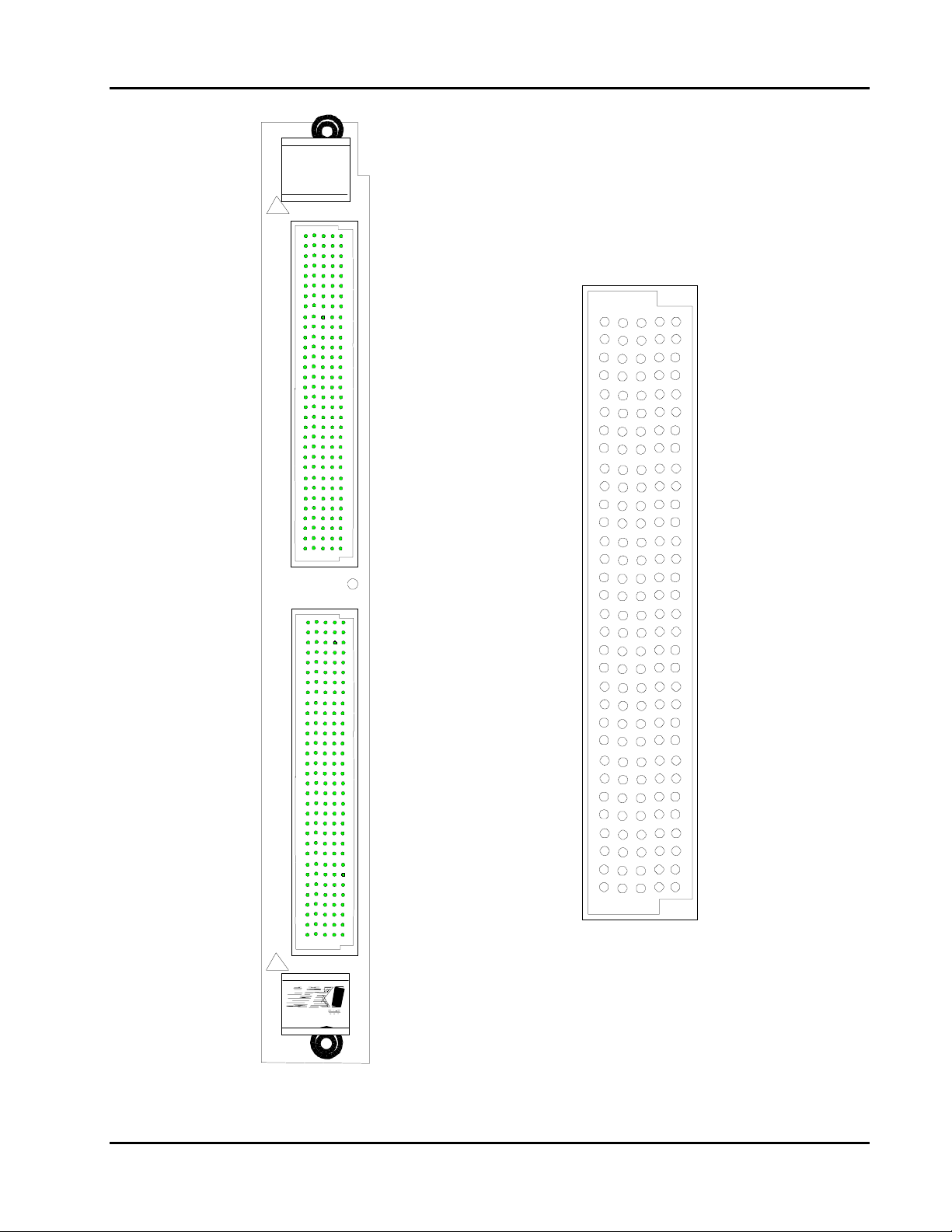
The 1260-38 front panel connectors are labeled J200 and J201.
The connector type is 5 x 32 (160-pin) DIN 41 612 male. T he pin
numbering is shown in Figure 3-3.
The mapping of channel numbers t o connector pins and the
available mating connector cable is given in Table 3-1.
There are no mating connectors shipped with the 1260-38 m odule.
Racal Instruments off er s t he following accessories for mating
connectors (see ordering infor m at ion for part numbers):
- 160-Pin Connector Kit with
backshell and pins
- 160-Pin Cable Assy,
6ft, 240A
- 160-Pin Cable Assy,
l2ft, 24GA
The 160-Pin Connector kit consists of a connector housing,
customized backshell and 170 crimp pins. The back shell design
has been optimized for system integration. The connector kit has
been designed for 22 to 26 gauge cable. The crimp pin will lock or
'click' into the connector housing only when installed correctly. The
assembler should ensure that the crimp pin is lock ed by tug ging
on the cable after insertion.
The hand crimp tool for loose crimp contacts is Erni Part Number
014 374. The disassembly tool is Erni Part Number 471 555.
The cable assemblies (optional lengths of 6ft. or 12ft.) use the
160-Pin Connector kit along with two 80-wire multi-colored 24
gauge cables. One end is un-terminat ed. Refer to Table 3.1 for the
mapping of channels to connector and cable.
Module Operation 3-3
Artisan Technology Group - Quality Instrumentation ... Guaranteed | (888) 88-SOURCE | www.artisantg.com

User Manual 1260-38
1260-38 Module
Specific Syntax
Syntax
The Module Specific Syntax for the 1260-38 is required in the use
of the OPEN and CLOSE commands. It will also appear in data
output by the Master in response to the PDATAOUT and PSETUP
commands.
The Module Specific Syntax for the 1260-38 Multiplexer/Scanner
module is as follows:
<COMMAND> relay designator> [;<relay designator>]
where:
<relay designator> ::= <module address>.<channel range>
[,<channel range>...]
<channel range> ::= <channel descriptor>[-<channel descriptor>]
<channel descriptor> ::= <interconnect><mux select><channel>
<module address> ::= 1.. 12
<interconnect> ::= 0 to 9
Where: 0 = multiplexer channels.
1 to 8 = multiplexer interconnect relays.
9 = one-wire high/low select.
<mux select> ::= 00 to 15
For two-wire mode: selects one of 16 1 x 8 multiplexers.
For four-wire mode: selects two of 16 1 x 8 mult iplexers.
Only even number multiplexers are allowed. Selecting
multiplexer 00 will also select same channel on next
multiplexer in sequence, in this case multiplexer 01.
<channel> ::= 0 to 7
0 to 7 for multiplexers
0 to 2 for interconnect relays
0 to 7 for one-wire relays
NOTE
Module Operation 3-4
Artisan Technology Group - Quality Instrumentation ... Guaranteed | (888) 88-SOURCE | www.artisantg.com
The <module address> used here is not the VXIbus

User Manual 1260-38
defined logical address of the 1260 Series Master. I t
is unique to the 1260 Series and describes the
switching module in rel at ion to the Master. This
address corresponds to the binary value of the switch
setting of SW1 on the switching module PCB. Refer
to the Installation Secti on of t he 1260 Series VXI
Switching Cards Manual for more information.
CLOSE Command
OPEN Command
The CLOSE command is used to close a channel.
Example:
CL[OSE] 1.0012
This CLOSE command will close channel 2 of multiplexer 0 1 on
the module at switch card module address 1.
The OPEN command is used to open a channel.
Example:
OP[EN] 3.0107
This OPEN command will open channel 7 of multiplexer 10 on the
module at switch card module address 3.
Note that channels remain closed until opened by an OPEN
command, RESET command, VXI hard or soft reset, or power-off.
PDATAOUT
Command
Artisan Technology Group - Quality Instrumentation ... Guaranteed | (888) 88-SOURCE | www.artisantg.com
The PDATAOUT command causes the specified module to
transmit the CLOSED state of the relays within the switch module
to the 1260 Controller. The syntax used is:
PD[ATAOUT] <module address> [;<module address>] [;<module address>]
The responses to the PDATAOUT command is as follows:
1260-38: Two-wire
<module address>. 1260-38A 1x128 2-WIRE SCANNER/MULTIPLEXER
<module address> . <channel range>[,<channel range>] [,<channel range>]
<module address>.END
1260-38 Four-Wire
<module address>. 1260-38B 1x64 4-WIRE SCANNER/MULTIPLEXER
<module address> . <channel range>[,<channel range>] [,<channel range>]
Module Operation 3-5

User Manual 1260-38
<module address>.END
The response to the PDATAOUT com mand consists of a header
on the first line as with the PSETUP response. The next line
details the channels currently closed on the module and is blank
when no channels are closed. Again, the last line is denoted by the
11
END'1 string of characters.
PSETUP Command
The PSETUP command causes the specified m odule setup to be
transmitted to the VXI Cont r o ller . The syntax used is:
PS[ETUP] <module address>[ ;<module address>] [;<module address>]
Where:
<module address> is the switch card address.
The responses to the PSETUP command for the 1260-38
Multiplexer/Scanner is as follows:
1260-38: Two-wire
<module address>. 1260-38A 1x128 2-WIRE SCANNER/MULTIPLEXER
<module address> . BBM
<module address>.END
1260-38 Four-Wire
<module address>. 1260-38B 1x64 4-WIRE SCANNER/MULTIPLEXER
<module address>. BBM
<module address>.END
The response to the PSETUP command consists of a header on
the first line. The header descr ibes the model number following an
A or B designating two or four - wire, r espectively. The next line
designates the setup mode for scanning which, by default, is
Break-Before-Make ( BBM). The last line containing the "END"
characters denotes no more inform ation to report.
Module Operation 3-6
Artisan Technology Group - Quality Instrumentation ... Guaranteed | (888) 88-SOURCE | www.artisantg.com

User Manual 1260-38
Figure 3-1, 1260-38 Module Configurati on Block Diagram
Module Operation 3-7
Artisan Technology Group - Quality Instrumentation ... Guaranteed | (888) 88-SOURCE | www.artisantg.com

User Manual 1260-38
Figure 3-2, 1260-38 Multiplexer Configuration Block Diagram
Module Operation 3-8
Artisan Technology Group - Quality Instrumentation ... Guaranteed | (888) 88-SOURCE | www.artisantg.com
User Manual 1260-38
1260-38
Racal
In s tru m e n ts
!
J
2
0
0
FA IL
J
2
0
1
a b c d e
32
31
30
29
28
27
26
25
24
23
22
21
20
19
18
17
16
15
14
13
12
11
10
9
8
7
6
5
4
3
2
1
!
Figure 3-2, 1260-38 Pin Connections, Front Vi ew
Module Operation 3-9
Artisan Technology Group - Quality Instrumentation ... Guaranteed | (888) 88-SOURCE | www.artisantg.com

Table 3-1, 1260-38 Channel Number/Connector Pin/Cable Mappi ng
Multiplexer 00
Channel # Connector Pin # Connect or I Cabl e # I Color
0000 Hi J200P31A P200, CABLE 1, white/black/orange/violet
0000 Lo J200P32A P200, CABLE 1, white/black/yellow/grey
0001 Hi J200P31B P200, CABLE 1, white/black/orange/grey
0001 Lo J200P32B P200, CABLE 1, white/black/green/blue
0002 Hi J200P31D P200, CABLE 1, white/black/yellow/blue
0002 Lo J200P32D P200, CABLE 1, white/black/green/grey
0003 Hi J200P31E P200, CABLE 1, white/blac k/yellow/violet
0003 Lo J200P32E P200, CABLE 1, white/black/blue/violet
0004 Hi J200P29A P200, CABLE 1, white/blac k/brown/violet
0004 Lo J200P30A P200, CABLE 1, white/black/red/violet
0005 Hi J200P29B P200, CABLE 1, white/black/brown/grey
0005 Lo J200P30B P200, CABLE 1, white/black/red/grey
0006 Hi J200P29D P200, CABLE 1, white/black/red/green
0006 Lo J200P30D P200, CABLE 1, white/black/orange/green
0007 Hi J200P29E P200, CABLE 1, white/black/red/blue
0007 Lo J200P30E P200, CABLE 1, white/black/orange/blue
COM00 Hi J200P31C P200, CABLE 1, white/black/yellow/green
COM00 Lo J200P32C P200, CABLE 1, white/black/green/violet
COM00R Hi J200P27C P200, CABLE 1, white/blue/violet
COM00R Lo J200P28C P200, CABLE 1, white/black/brown/yellow
COM001W J200P30C P200, CABLE 1, white/ bl ack/orange/yellow
COM00lWR J200P29C P200, CABLE 1, white/black/red/yellow
User Manual 1260-38
Multiplexer 01
Channel # Connector Pin # Connector / Cabl e # I Color
0010 Hi 3200P27A P200, CABLE 1, white/green/violet
0010 Lo J200P28A P200, CABLE 1, white/black/brown/red
0011 Hi 3200P27B P200, CABLE 1, white/green/grey
0011 Lo J200P28B P200, CABLE 1, white/black/brown/orange
0012 Hi J200P27D P200, CABLE 1, white/blue/grey
0012 Lo J200P28D P200, CABLE 1, white/black/ brown/green
0013 Hi J200P27E P200, CABLE 1, white/violet/grey
0013 Lo J200P28E P200, CABLE 1, white/black/brown/blue
0014 Hi J200P25A P200, CABLE 1, white/orange/yellow
0014 Lo 3200P26A P200, CABLE 1, white/yellow/green
0015 Hi 3200P25B P200, CABLE 1, white/orange/green
0015 Lo J200P26B P200, CABLE 1, white/yellow/blue
0016 Hi J200P25D P200, CABLE 1, white/orange/violet
0016 Lo 3200P26D P200, CABLE 1, white/yellow/grey
0017 Hi J200P25E P200, CABLE 1, white/orange/grey
0017 Lo 3200P26E P200. CABLE 1, white/green/blue
COM01 Hi J200P25C P200, CABLE 1, white/orange/blue
COM01 Lo J200P26C P200, CABLE 1, white/yellow/violet
Module Operation 3-10
Artisan Technology Group - Quality Instrumentation ... Guaranteed | (888) 88-SOURCE | www.artisantg.com

User Manual 1260-38
Table 3-1, 1260-38 Channel Number/Connector Pin/Cable Mappi ng Continued
Multiplexer 02
Channel # Connector Pin # Connector / Cable # / Color
0020 Hi J200P23A P200, CABLE 1, white/brown/green
0020 Lo J200P24A P200, CABLE 1, white/ red/yellow
0021 Hi J200P23B P200, CABLE 1, white/brown/blue
0021 Lo J200P24B P200, CABLE 1, white/red/green
0022 Hi J200P23D P200, CABLE 1, white/brown/grey
0022 Lo 3200P24D P200, CABLE 1, white/red/violet
0023 Hi J200P23E P200, CABLE 1, white/red/orange
0023 Lo J200P24E P200, CABLE 1, white/red/grey
0024 Hi J200P21A P200, CABLE 1, white/black/red
0024 Lo J200P22A P200, CABLE 1, white/black/violet
0025 Hi J200P21B P200, CABLE 1, white/black/orange
0025 Lo J200P22B P200, CABLE 1, white/black/grey
0026 Hi J200P21D P200, CABLE 1, white/black/green
0026 Lo J200P22D P200, CABLE 1, white/brown/orange
0027 Hi J200P21E P200, CABLE 1, white/black/blue
0027 Lo J200P22E P200, CABLE 1, white/ brown/yell ow
COM02 Hi J200P23C P200, CABLE 1, white/brown/violet
COM02 Lo J200P24C P200, CABLE 1, white/red/blue
COM02R Hi J200P19C P200, CABLE 1, white/red
COM02R Lo J200P20C P200, CABLE 1, white/violet
COM021W J200P22C P200, CABLE 1, white/brown/red
COM021WR J200P21C P200, CABLE 1, white/black/yellow
Multiplexer 03
Channel # Connector Pin # Connect or / Cable # I Color
0030 Hi J200P19A P200, CABLE 1, white/black
0030 Lo J200P20A P200, CABLE 1, white/green
0031 Hi J200P19B P200, CABLE 1, white/brown
0031 Lo J200P20B P200, CABLE 1, white/blue
-0032 Hi J200P19D P200, CABLE 1, white/orange
-0032 Lo J200P20D P200, CABLE 1, white/grey
0033 Hi 1200P19E P200, CABLE 1, white/yellow
0033 Lo J200P20E P200, CABLE 1, white/black/brown
0034 Hi J200P17A P200, CABLE 1, black
0034 Lo J200P18A P200, CABLE 1, green
0035 Hi J200P17B P200, CABLE 1, brown
0035 Lo J200Pl8B P200, CABLE 1, blue
0036 Hi J200P17D P200, CABLE 1, orange
0036 Lo J200Pl8D P200, CABLE 1, grey
0037 Hi J200P17E P200, CABLE 1, yellow
0037 Lo J200P18E P200. CABLE 1, white
COM03 Hi J200P17C P200, CABLE 1, red
COM03 Lo J200P18C P200, CABLE 1, violet
Module Operation 3-11
Artisan Technology Group - Quality Instrumentation ... Guaranteed | (888) 88-SOURCE | www.artisantg.com

Table 3-1, 1260-38 Channel Number/Connector Pin/Cable Mappi ng Continued
Multiplexer 04
Channel # Connector Pin # Connector / Cable # / Color
0040 Hi J200P15A P200, CABLE 2, white/black/orange/vi ol et
0040 Lo J200P16A P200, CA B LE 2, white/black/yellow/grey
0041 Hi J200P15B P200, CABLE 2, white/black/orange/grey
0041 Lo J200P16B P200, CA B LE 2, white/black/green/blue
0042 Hi J200P15D P200, CABLE 2, white/black/yellow/blue
0042 Lo J200P16D P200, CABLE 2, white/black/green/grey
0043 Hi J200P15E P200, CABLE 2, white/black/yell ow/viol et
0043 Lo J200P16E P200. CA B LE 2. white/black/blue/violet
0044 Hi J200P13A P200, CABLE 2, white/black/brown/violet
0044 Lo J200P14A P200, CA BLE 2, white/black/red/violet
0045 Hi J200P13B P200, CABLE 2, white/black/brown/grey
0045 Lo J200Pl4B P200, CABLE 2, white/black/red/grey
0046 Hi J200P13D P200, CABLE 2, white/black/red/green
0046 Lo J200P14D P200, CABLE 2, white/black/orangelgreen
0047 Hi J200P13E P200, CABLE 2, white/black/red/blue
0047 Lo J200Pl4E P200, CABLE 2, white/black/orange/blue
COM04 Hi J 200P15C P200, CABLE 2, white/blac k/yellow/green
COM04 Lo J200P16C P 200, CABLE 2, white/black/green/violet
COM04R Hi J200P 11C P200, CABLE 2, white/blue/violet
COM04R Lo J200P12C P 200, CABLE 2, white/black/brown/yellow
COM041W J200P14C P200, CABLE 2, white/black/orange/yellow
COM041WR J200P13C P 200, CABLE 2, white/black/red/yellow
User Manual 1260-38
Multiplexer 05
Channel # Connector Pin # Connector / Cable # / Color
0050 Hi J200P11A P200, CAB LE 2, white/green/violet
0050 Lo J200P12A P200, CA B LE 2, white/black/brown/red
0051 Hi J200P11B P200, CAB LE 2, white/green/grey
0051 Lo J200P12B P200, CA B LE 2, white/black/brown/orange
0052 Hi J200P11D P200, CABLE 2, white/blue/grey
0052 Lo J200P12D P200, CABLE 2, white/black/brown/green
0053 Hi J200P11E P200, CABLE 2, white/violet/grey
0053 Lo J200P12E P200, CA B LE 2, white/black/brown/blue
0054 Hi J200P9A P200, CABL E 2, white/orange/yellow
0054 Lo J200P10A P200, CA B LE 2, white/yellow/green
0055 Hi J200P9B P200, CABLE 2, white/orange/green
0055 Lo J200P10B P200, CA B LE 2, white/yellow/blue
0056 Hi J200P9D P200, CABLE 2, white/orange/violet
0056 Lo J200P10D P200, CABLE 2, white/yellow/grey
0057 Hi J200P9E P200, CABLE 2, white/orange/grey
0057 Lo J200P10E P200, CA B LE 2, white/green/blue
COM05 Hi J 200P9C P200, CABLE 2, white/orange/blue
COM05 Lo J200P10C P 200, CABLE 2, white/yellow/violet
Module Operation 3-12
Artisan Technology Group - Quality Instrumentation ... Guaranteed | (888) 88-SOURCE | www.artisantg.com

User Manual 1260-38
Table 3-1, 1260-38 Channel Number/Connector Pin/Cable Mappi ng Continued
Multiplexer 06
Channel # Connector Pin # Connector / Cable # / Color
0060 Hi J200P7A P200, CABLE 2, white/brown/green
0060 Lo J200P8A P200, CABLE 2, white/ red/yellow
0061 Hi J200P7B P200, CABLE 2, white/brown/blue
0061 Lo J200P8B P200, CABLE 2, white/ red/green
0062 Hi J200P7D P200, CABLE 2, white/brown/grey
0062 Lo J200P8D P200, CABLE 2, white/red/violet
0063 Hi J200P7E P200, CABLE 2, white/red/orange
0063 Lo J200P8E P200, CABLE 2. white/ red/grey
0064 Hi J200P5A P200, CABLE 2, white/black/red
0064 Lo J200P6A P200, CABLE 2, white/black/violet
0065 Hi J200P5B P200, CABLE 2, white/black/orange
0065 Lo J200P6B P200, CABLE 2, white/ bl ack/grey
0066 Hi J200P5D P200, CABLE 2, white/black/green
0066 Lo J200P6D P200, CABLE 2, white/brown/orange
0067 Hi J200P5E P200, CABLE 2, white/black/blue
0067 Lo J200P6E P200, CABLE 2, white/ brown/yell ow
COM06 Hi J200P7C P 200, CABLE 2, white/brown/violet
COM06 Lo J200P8C P200, CABLE 2, white/red/blue
COM06R Hi J200P 3C P200, CABLE 2, white/red
COM06R Lo J200P4C P200, CABLE 2, white/violet
COM061W J200P6C P200, CABLE 2, white/brown/red
COM061WR J200P5C P200, CABLE 2, white/black/yell o w
Multiplexer 07
Channel # Connector Pin # Connector / Cable # I Color
0070 Hi J200P3A P200, CA BLE 2, white/black
0070 Lo J200P4A P200, CABLE 2, white/green
0071 Hi J200P3B P200, CA BLE 2, white/brown
0071 Lo J200P4B P200, CABLE 2, white/blue
0072 Hi J200P3D P200, CABLE 2, white/orange
0072 Lo J200P4D P200, CABLE 2, white/grey
0073 Hi J200P3E P200, CABLE 2, white/yellow
0073 Lo J200P4E P200, CABLE 2, white/black/brown
0074 Hi J200P1A P200, CA BLE 2, black
0074 Lo J200P2A P200, CABLE 2, green
0075 Hi J200P1B P200, CABLE 2, brown
0075 Lo J200P2B P200, CABLE 2, blue
0076 Hi J200P1D P200, CABLE 2, orange
0076 Lo J200P2D P200, CABLE 2, grey
0077 Hi J200P1E P200, CABLE 2, yellow
0077 Lo J200P2E P200, CABLE 2, white
COM07 Hi J 200P1C P200, CABLE 2, red
COM07 Lo J200P2C P200, CABLE 2, violet
Module Operation 3-13
Artisan Technology Group - Quality Instrumentation ... Guaranteed | (888) 88-SOURCE | www.artisantg.com

Table 3-1, 1260-38 Channel Number/Connector Pin/Cable Mappi ng Continued
Multiplexer 08
Channel # Connector Pin # Connector / Cable # / Color
0080 Hi J201P31A P201, CABLE 1, white/black/orange/violet
0080 Lo J201P32A P201, CABLE 1, white/black/yellow/grey
0081 Hi J201P31B P201, CABLE 1, white/black/orange/grey
0081 Lo J201P32B P201, CABLE 1, white/black /green/blue
0082 Hi J201P31D P201, CABLE 1, white/black/yellow/blue
0082 Lo J201P32D P201, CABLE 1, white/black/green/grey
0083 Hi J201P31E P201, CABLE 1, white/black /yellow/violet
0083 Lo J201P32E P201, CABLE 1, white/black/blue/violet
0084 Hi J201P29A P201, CABLE 1, white/black / brown/viol et
0084 Lo J201P30A P201, CABLE 1, white/black/red/violet
0085 Hi J201P29B P201, CABLE 1, white/black/brown/grey
0085 Lo J201P30B P201, CABLE 1, white/black /red/grey
0086 Hi J201P29D P201, CABLE 1, white/black/red/green
0086 Lo J201P30D P201, CABLE 1, white/black/orange/green
0087 Hi J201P29E P201, CABLE 1, white/black/red/blue
0087 Lo 3201P30E P 201, CABLE 1, white/black/orange/blue
COM08 Hi J 201P31C P201, CABLE 1, white/black / yellow/green
COM08 Lo J201P32C P201, CABLE 1, white/black/green/violet
COM08R Hi J201P 27C P201, CABLE 1, white/blue/violet
COM08R Lo J201P28C P201, CABLE 1, white/black/brown/yellow
COM081W J201P30C P 201, CABLE 1, white/black/orange/yellow
COM081WR J201P29C P201, CABLE 1, white/black/red/yellow
User Manual 1260-38
Multiplexer 09
Channel # Connector Pin # Connector / Cable # I Color
0090 Hi J201P27A P201, CABLE 1, white/green/violet
0090 Lo J201P28A P201, CABLE 1, white/black /brown/red
0091 Hi J201P27B P201, CABLE 1, white/green/grey
0091 Lo J201P28B P201, CABLE 1, white/black /brown/orange
0092 Hi J201P27D P201, CABLE 1, white/blue/grey
0092 Lo J201P28D P201, CABLE 1, white/black/brown/green
0093 Hi J201P27E P201, CABLE 1, white/violet/ grey
0093 Lo J201P28E P201, CABLE 1, white/black /brown/blue
0094 Hi J201P25A P201, CABLE 1, white/orange/yellow
0094 Lo J201P26A P201, CABLE 1, white/yellow/green
0095 Hi J201P25B P201, CABLE 1, white/orange/green
0095 Lo J201P26B P201, CABLE 1, white/yellow/blue
0096 Hi J201P25D P201, CABLE 1, white/orange/violet
0096 Lo J201P26D P201, CABLE 1, white/yellow/grey
0097 Hi J201P25E P201, CABLE 1, white/orange/grey
0097 Lo J201P26E P201, CABLE 1, white/green/blue
COM09 Hi J 201P25C P201, CABLE 1, white/orange/blue
COM09 Lo J201P26C P201, CABLE 1, white/yellow/violet
Module Operation 3-14
Artisan Technology Group - Quality Instrumentation ... Guaranteed | (888) 88-SOURCE | www.artisantg.com

User Manual 1260-38
Table 3-1, 1260-38 Channel Number/Connector Pin/Cable Mappi ng Continued
Multiplexer 10
Channel # Connector Pin # Connector / Cable # I Color
0100 Hi J201P23A P201, CAB LE 1, white/brown/green
0100 Lo J201P24A P201, CAB LE 1, white/red/yellow
0101 Hi J201P23B P201, CAB LE 1, white/brown/blue
0101 Lo J201P24B P201, CABLE 1, white/red/green
0102 Hi J201P23D P 201, CABLE 1, white/brown/grey
0102 Lo 3201P24D P201, CABLE 1, white/ red/violet
0103 Hi J201P23E P201, CAB LE 1, white/red/orange
0103 Lo J201P24E P201, CABLE 1, white/red/grey
0104 Hi J201P21A P201, CAB LE 1, white/black/red
0104 Lo J201P22A P201, CAB LE 1, white/black/violet
0105 Hi J201P21B P201, CAB LE 1, white/black/orange
0105 Lo J201P22B P201, CABLE 1, white/black/grey
0106 Hi J201P21D P 201, CABLE 1, white/black/green
0106 Lo J201P22D P 201, CABLE 1, white/brown/orange
0107 Hi J201P21E P201, CAB LE 1, white/black/blue
0107 Lo J201P22E P201, CAB LE 1, white/brown/yellow
COM10 Hi J201P23C P201, CABLE 1, white/brown/violet
COM10 Lo J201P24C P201, CABLE 1, white/red/blue
COM10R Hi J201P19C P 201, CABLE 1, white/red
COM110R Lo J201P20C P 201, CABLE 1, white/violet
COM101W J201P22C P201, CABLE 1, white/brown/red
COM101WR J201P21C P 201, CABLE 1, white/black/yellow
Multiplexer 11
Channel # Connector Pin # Connector I Cable # I Color
0110 Hi J201P19A P201, CAB LE 1, white/black
0110 Lo J201P20A P201, CABLE 1, white/green
0111 Hi J201PI9B P201, CABLE 1, white/ brown
0111 Lo J201P20B P201, CABLE 1, white/blue
0112 Hi J201P19D P 201, CABLE 1, white/orange
0112 Lo J201P20D P 201, CABLE 1, white/grey
0113 Hi J201P19E P201, CAB LE 1, white/yellow
0113 Lo J201P20E P201, CABLE 1, white/black/brown
0114 Hi J201P17A P201, CAB LE 1, black
0114 Lo J201P18A P201, CABLE 1, green
0115 Hi 3201P17B P 201, CABLE 1, brown
0115 Lo J201P18B P201, CABLE 1, blue
0116 Hi J201P17D P 201, CABLE 1, orange
0116 Lo J201P18D P 201, CABLE 1, grey
0117 Hi J201P17E P201, CAB LE 1, yellow
0117 Lo J201P18E P201, CABLE 1, white
COM11Hi J201P17C P 201, CABLE 1 ,red
COM11 Lo J201P18C P201, CABLE 1, violet
Module Operation 3-15
Artisan Technology Group - Quality Instrumentation ... Guaranteed | (888) 88-SOURCE | www.artisantg.com

Table 3-1, 1260-38 Channel Number/Connector Pin/Cable Mappi ng Continued
Multiplexer 12
Channel # Connector Pin # Connector / Cable # / Color
0120 Hi J201P15A P201, CABLE 2, white/black/orange/violet
0120 Lo J201P16A P201, CABLE 2, white/black/yellow/grey
0121 Hi J201P15B P201, CABLE 2, white/black/orange/grey
0121 Lo J201P16B P201, CABLE 2, white/black/green/blue
0122 Hi J201P15D P201, CABLE 2, white/black/yellow/blue
0122 Lo J201P16D P201, CA BLE 2, white/black/green/grey
0123 Hi J201P15E P201, CABLE 2, white/blac k/yellow/violet
0123 Lo J201P16E P201, CABLE 2, white/black/blue/violet
0124 Hi J201P13A P201, CABLE 2, white/blac k/brown/violet
0124 Lo J201P14A P201, CABLE 2, white/black/red/violet
0125 Hi J201P13B P201, CABLE 2, white/black/brown/grey
0125 Lo J201P14B P201, CABLE 2, white/black/red/grey
0126 Hi J201P13D P201, CA BLE 2, white/black/red/green
0126 Lo J201P14D P201, CA BLE 2, white/black/orange/green
0127 Hi J201P13E P201, CABLE 2, white/black/red/blue
0127 Lo J201P14E P201, CABLE 2, white/black/orange/blue
COM12 Hi J201P15C P201, CABLE 2, white/black/yellow/green
COM12 Lo J201P16C P201, CABLE 2, white/black/green/violet
COM12R Hi J201P11C P201, CABLE 2, white/blue/violet
COM12R Lo J201P12C P201, CABLE 2. white/black/ brown/yell ow
COM121W J201P14C P201, CABLE 2, white/black/orange/yellow
COM121WR J201P13C P201, CA BLE 2, white/black/red/yellow
User Manual 1260-38
Multiplexer 13
Channel # Connector Pin # Connector / Cable # /I Color
0130 Hi J201P11A P201, CABLE 2, white/green/viol et
0130 Lo J201P12A P201, CABLE 2, white/black/brown/red
0131 Hi J201P11B P201, CABLE 2, white/green/grey
0131 Lo J201 P12B P201, CABLE 2, white/ bl ack/brown/orange
0132 Hi J201P11D P201, CA BLE 2, white/blue/grey
0132 Lo J201P12D P201, CA BLE 2, white/black/brown/green
0133 Hi J201P11E P201, CABLE 2, white/violet/grey
0133 Lo J201P12E P201, CABLE 2, white/black/brown/blue
0134 Hi J201P9A P201, CABLE 2, white/orange/yellow
0134 Lo J201P10A P201, CABLE 2, white/yellow/green
0135 Hi J201P9B P201, CABLE 2, white/orange/green
0135 Lo J201P10B P201, CABLE 2, white/yellow/blue
0136 Hi J201P9D P201, CABLE 2, white/orange/violet
0136 Lo J201P10D P201, CA BLE 2, white/yellow/grey
0137 Hi J201P9E P201, CABLE 2, white/orange/grey
0137 Lo J201P10E P201, CABLE 2, white/green/blue
COM13 Hi J201P9C P201, CABLE 2, white/orange/blue
COM13 Lo J201P10C P201, CABLE 2, white/yellow/violet
Module Operation 3-16
Artisan Technology Group - Quality Instrumentation ... Guaranteed | (888) 88-SOURCE | www.artisantg.com

User Manual 1260-38
Table 3-1, 1260-38 Channel Number/Connector Pin/Cable Mappi ng Continued
Multiplexer 14
Channel # Connector Pin # Connector / Cable # I Color
0140 Hi J201P7A P201, CABLE 2, white/brown/green
0140 Lo J201P8A P201, CABLE 2, white/red/yellow
0141 Hi J201P7B P201, CABLE 2, white/brown/blue
0141 Lo J201P8B P201, CABLE 2, white/red/green
0142 Hi J201P7D P201, CABLE 2, white/brown/grey
0142 Lo J201P8D P201, CABLE 2, white/red/viol et
0143 Hi J201P7E P201, CABLE 2, white/red/orange
0143 Lo J201P8E P201. CABLE 2. white/red/grey
0144 Hi J201P5A P201, CABLE 2, white/black/red
0144Lo J201P6A P201, CAB LE 2, white/black/violet
0145 Hi J201P5B P201, CABLE 2, white/black/orange
0145 Lo J201P6B P201, CABLE 2, white/black/grey
0146 Hi J201PSD P201, CABLE 2, white/black/green
0146 Lo J201P6D P201, CABLE 2, white/brown/orange
0147 Hi J201P5E P201, CABLE 2, white/black/blue
0147 Lo J201P6E P201, CABLE 2, white/brown/yellow
COM14 Hi J201P7C P201, CABLE 2, white/brown/violet
COM 14 Lo J 201P 8C P201, CA B LE 2, white/red/blue
COM14R Hi J201P 3C P201, CAB L E 2, white/red
COM14R Lo J201P4C P201, CABLE 2, white/violet
COM141W J201P6C P201, CABLE 2, white/brown/red
COM141WR J201P5C P201, CABLE 2, white/ bl ack/yellow
Multiplexer 15
Channel # Connector Pin # Connector / Cable # / Color
0150 Hi J201P3A P201, CABLE 2, white/black
0150 Lo J201P4A P201, CAB LE 2, white/green
0151 Hi J201P3B P201, CABLE 2, white/brown
0151 Lo J201P4B P201, CAB LE 2, white/blue
0152 Hi J201P3D P201, CABLE 2, white/orange
0152 Lo J201P4D P201, CABLE 2, white/grey
0153 Hi J201P3E P201, CABLE 2, white/yellow
0153 Lo J201P4E P201, CAB LE 2, white/black/brown
0154 Hi J201P1A P201, CABLE 2, black
0154 Lo J201P2A P201, CAB LE 2, green
0155 Hi J201P1B P201, CABLE2, brown
0155 Lo J201P2B P201, CAB LE2, blue
0156 Hi J201P1D P201, CABLE2, orange
0156 Lo J201P2D P201, CABLE2.grey
0157 Hi J201P1E P201, CABLE2, yellow
0157 Lo J201P2E P201, CAB LE 2, white
COM15Hi J201P1C P201, CAB LE2, red
COM15 Lo J201P2C P201, CABLE 2, violet
Module Operation 3-17
Artisan Technology Group - Quality Instrumentation ... Guaranteed | (888) 88-SOURCE | www.artisantg.com

Table 3-1, 1260-38 Channel Number/Connector Pin/Cable Mappi ng Continued
Interconnecting Channels
Channel # Path
1000 COM 00 TO COM 02
1001 COM 01 TO COM 03
1002 COM 00 TO COM 01
2000 COM 02 TO COM 04
2001 COM 03 TO COM 05
2002 COM 02 TO COM 03
3000 COM 04 TO COM 06
3001 COM 05 TO COM 07
3002 COM 04 TO COM 05
4000 COM 06 TO COM 08
4001 COM 07 TO COM 09
4002 COM 06 TO COM 07
5000 COM 08 TO COM 10
5001 COM 09 TO COM 11
5002 COM 08 TO COM 09
6000 COM 10 TO COM 12
6001 COM 11 TO COM 13
6002 COM 10 TO COM 11
7000 COM 12 TO COM 14
7001 COM 13 TO COM 15
7002 COM 12 TO COM 13
8000 COM 14 TO COM 15
One-Wire Channels
9000 COM 001W - open connects to COM00 Hi
9001 COM 021W - open connects to COM02 Hi
9002 COM 041W - open connects to COM04 Hi
9003 COM 061W - open connects to COM06 Hi
9004 COM 081W - open connects to COM08 Hi
9005 COM 101W - open connects to COM10 Hi
9006 COM 121W - open connects to COM12 Hi
9007 COM 141W - open connects to COM14 Hi
User Manual 1260-38
- close connects to COM00 Lo
COM001WR - open connects to COM00R Hi
- close connects to COM00R Lo
- close connects to COM02 Lo
COM021WR - open connects to COM02R Hi
- close connects to COM02R Lo
- close connects to COM04 Lo
COM041WR - open connects to COM04R Hi
- close connects to COM04R Lo
- close connects to COM06 Lo
COM061WR - open connects to COM06R Hi
- close connects to COM06R Lo
- close connects to COM08 Lo
COM081WR - open connects to COM08R Hi
- close connects to COM08R Lo
- close connects to COM10 Lo
COM101WR - open connects to COM10R Hi
- close connects to COM10R Lo
- close connects to COM12 Lo
COM121WR - open connects to COM12R Hi
- close connects to COM12R Lo
- close connects to COM14 Lo
COM141WR - open connects to COM14R Hi
- close connects to COM14R Lo
Module Operation 3-18
Artisan Technology Group - Quality Instrumentation ... Guaranteed | (888) 88-SOURCE | www.artisantg.com

User Manual 1260-38
DRAWINGS
407410 Final Assembly, 1260-38............................................................................4-3
405100 PCB Assembly, 1260-38............................................................................4-4
435100 Schematic, 1260-38...................................................................................4-5
Front Panel Connector Accessories
Chapter 4
407407 160-Pin Connector Kit with backshell and pins.........................................4-28
407408 160-Pin Cable Assy, 6ft., 24GA................................................................4-29
407409 160-Pin Cable Assy, 12ft., 24GA..............................................................4-30
Drawings 4-1
Artisan Technology Group - Quality Instrumentation ... Guaranteed | (888) 88-SOURCE | www.artisantg.com

This page was left intentionally blank.
User Manual 1260-38
Drawings 4-2
Artisan Technology Group - Quality Instrumentation ... Guaranteed | (888) 88-SOURCE | www.artisantg.com

User Manual 1260-38
D
APPROVEDDATEDESCR IPTION
3/13/96 db
AMN 09/16/98
B
REV.SH.
REVI SIONS
1
C
13
( )
2
B
7
( )
29
10
( )
16
( )
A
B
2
OF
1
17
SHEET
CALC.WT ACT.WT
407410
980346 RE V. F
DWG NO.REV.
1260-38,2W,1X128
SC MUX, 2AMP
CAG E CO DE
4 Goodyear St.,Ir vine,CA.92718-2002
TITLE
1/2
SCALE
SIZE
234
REVISED PER EO NO.
REVISED PER EO NO.
REVISED PER EO NO.
REVISED PER EO NO.
REVISED PER EO NO.
RELEASED PER DRN NO. 1557
A
B REVISED PER EO NO. 24415
407410
REV
ZONE
DWG. NO.
PART OF
ITE M 37
1.0
10
34568 1
10 7
( ) ( )
5
13
1
.7
LOGICAL ADDRESS SELECT
0
1
12345678
INTERRUPT S ELECT
0
1
4
123
.7
29
2 PLCS
7
( )
35
PART OF
1.0
SENSITIVE ELECTRONIC D EVICES
DO NOT OPEN EXC EPT AT
APPROVED FIE LD FORCE
PROTECTIVE WORK ST ATION
ITE M 20
19
11 19
( ) ( ) ( )
( )
PART OF
ITE M 36
Instruments
Racal
16
19
( )
24
16
( )
11
12
( )
( )
PART OF
8 PLCS
ITE M 36
5
11
( )
113212
7
18
( )
( )
1823
12
( )
11
12
68
4
282 PLCS
PART OF
ITE M 20
137 19
7
123456
1
0
ID
CARD ADDR
BYTE
CLOSE
OPEN
612345234
156
30
4 PLCS
6
PROPRIETARY NOTI CE
AFFIX LABELS PART OF ITEM 37 AS SHOWN. ALI GN
LABEL TEXT WITH APPROPRIA TE SWITCH ACTUATORS.
NOTE NOT USED.
APPLY LOCTITE (ITEM 33) SPARINGLY TO ALL SCREWS
THA T DO NOT USE MECHA NICAL L OCKING HARDWARE . DO
NOT ALLOW C O NTACT WITH EJECTOR HANDLES (ITEM 19
TOP), AND (ITE M 18 BO TTOM).
ATTACH B UMPER (ITEM 32) TO CIRCUIT SIDE OF PCB
DIS CARD UNUSE D HAR D WARE PART OF ITEM 20.
2
THIS DOCUMENT AND THE TECHNICAL DAT A HEREON DISCLOSED ARE PR OPR IETARY
TO RA C AL INS TR UM E NT S INC. AN D SH ALL NOT, W ITHO UT THE EX PRE SS WRITTE N
PERM ISS IO N OF RA C AL IN STRUMENTS INC . BE US ED, RELEASED OR D I SCLOSED
IN WHOLE OR IN PART , O R U SE D TO SOLI C IT Q U O TA T IO N FROM A COMP E TITIVE
SOURCE OR USE D FOR MANUFACTURE B Y ANYONE OTHER THA N RACAL INST RUMENTS
1.
INC. THE INFORM A TION HER EO N HA S BEEN D EV ELO PED AT PRIV ATE EXP EN SE,
AND MAY ON LY BE USED FO R PU RPO S ES OF ENG INE ERING EVA LU ATION AND FOR
INCORPORATI ON INTO TECHNICAL SPECIFI CATIONS AND OTHER DOCUMENT S WHICH
SPECIFY PROCUREMENT OF PRODUCTS FROM RACAL INSTRUMENTS I NC.
NOTES:
4
3.
D
ASSEMBLY (ITEM 7) APPROXIM A TELY WHERE SHOWN .
LOCATE APPROPRIATE VXI LABEL WHERE SHOW N .
RE F ERENC E 9 2 1 4 1 0 F OR SPE CIFIC L A B E L IN F ORM ATION.
5
6
PART OF
2
C
29
PART OF
ITE M 37
3 PLCS
ITE M 37
2
B
A
Drawings 4-3
Artisan Technology Group - Quality Instrumentation ... Guaranteed | (888) 88-SOURCE | www.artisantg.com

User Manual 1260-38
REV.
SH.
405100
DWG. NO.
D
APPROVEDDATEDESCRIPTION
1557
A
REVISIONS
1
REVISED PER EO NO.
REVISED PER EO NO.
REVISED PER EO NO.
REVISED PER EO NO.
RELEASED PER DRN NO. 960308 D. BORDEN
REVISED PER EO NO.
REVISED PER EO NO.
A
REV
ZONE
2 PLCS
J3,4
35
2 PLCS
P1,2
9
71
C
10
INSTAL L COMPONENT SIDE
SWAGE CIRCUIT SIDE
64
INSTALL CIRCUIT SIDE
SWAGE COMPONENT SIDE
818267
B
TABLE 1 LOGICAL TEST AD DRESS
ADDRESS SW1:1 SW1:2 SW1:3 SW1:4 R/W ID BYTE READ 0 OFF O FF OFF OFF (illegal) 1 OFF OFF OFF ON 4804xxh 4 80601h 2 OFF OFF ON OFF 4808xxh 4 80A01h 3 OFF OFF ON ON 480Cxxh 48 0E01h 4 OFF ON OFF OFF 4810xxh 4 81201h 5 OFF ON OFF ON 4814xxh 4816 01h 6 OFF ON ON OFF 4818xxh 481A 01h 7 OFF ON ON ON 481Cxxh 48 1E01h 8 ON OFF OFF OFF 4820xxh 4 82201h 9 ON OFF OFF ON 4824xxh 482 601h 10 ON OFF ON OF F 4828xxh 48 2A01h 11 ON OFF ON ON 482Cxxh 482E 01h 12 ON ON OFF OF F 4830xxh 48 3201h
13 ON ON OFF ON (illegal)
14 ON ON ON OFF (illegal) 15 ON ON ON ON (illegal)
A
A
2
OF
1
17
SHEET
CALC.WT ACT.WT
405100
980346 REV. F
DWG NO. REV.
CAGE CODE
4 Goodyear St.,Irvine,CA.92718-2002
PCB ASSY, 1260-38
TITLE
SIZE
SEE SEPARATE PARTS LIST
9
SCALE
234
34568 1
8
59 74
2-3 12V RLY
1-2 24V RLY
4
58
7
PROPRIETARY NOTICE
INSTALL (ITEM 59) PCB INTO (ITEM 74) J3.
SOLDER TAILS ON CIRCUIT SIDE OF PCB FOR J3 & J4 (ITEM 74)
8
SOLDER TAILS ON CIRCUIT SIDE OF PCB FOR P1 & P2
(ITEM 71)TO BE TRIMMED TO A MAXIMUM HEIGHT OF .045.
345
2 PLCS
TP1,2
2
3 ROWS (9 PINS) NEAREST EDGE OF PC BOARD TO BE TRIMMED
TO A MAXIMUM HEIGHT OF .045.
INSTALL JUMPER W1 PIN 1 TO W1 PIN 2 USING ITEM 64.
9
10
INSTALL (ITEM 58) PCB INTO (ITEM 74) J4.
P1 AND P2 MUST BE INSTALLED FLUSH AT
RIGHT ANGLE TO PCB.
SET SW1 (ITEM 75) TO LOGICAL ADDRESS 1 PER TABLE 1.
DO NOT WAVE SOLDER.
SET SW2 AND SW3 (ITEM 75) TO ON POSITION.
DO NOT WAVE SOLDER.
7
6
70
568
158 PLCS
K1-158
54 60
COMPONENT SIDE
THIS DOCUMENT AND THE TECHNICAL DATA HERE ON DISCLOSED ARE PROPRIETARY
TO RACAL INSTRUMENTS INC. AND SHALL NOT, WITHOUT THE EXPRESS WRITTEN
PERMISSION OF RACAL INSTRUMENTS INC. BE USED, RELEASE D OR DISCLOSED
IN WHOLE OR IN PART, OR USED TO SOLICIT QUOTATION FROM A COMPETITIVE
SOURCE OR USED FOR MA NUFACTURE BY ANYONE OTHER THAN RACAL INSTRUMENT S
INC. THE INFORMATION HEREON HAS BEEN DEVELOPED AT PRIVATE EXPENSE,
AND MAY ONLY BE USED FOR PURPOSES OF ENGINEERING EVALUATION AND FOR
INCORPORATION INTO TE CHNICAL SPECIFICATIONS AND OTHER DOCUMENTS WHICH
SPECIFY PROCUREMENT OF PRODUCTS FROM RACAL INSTRUMENTS INC.
Drawings 4-4
INK STAMP SERIAL NUMBER & CURRENT
REVISION ON COMPONENT SIDE APPROX.
WHERE SHOWN.
NOTES:
1. REFERENCE SCHEMATIC 435100.
2
78
D
81
INSTALL
CIRCUIT SIDE
SWAGE
COMPONENT SIDE
C
78
B
A
Artisan Technology Group - Quality Instrumentation ... Guaranteed | (888) 88-SOURCE | www.artisantg.com

User Manual 1260-38
U83W1Z128
HIGHEST
REF.DES.
C167
J201
K158L5P2Q1R20
SW3
TP2
10
7108881410
8108812
GND
16,17
PIN NO.
VRR
PIN NO.
SHEET 1 OF 23
SCHEM.,1260-38
4 Goodyear St., Irvine, Ca 92718-2002
20
74HC299
U82
14201616162820
1615201616
3
74HCT164
231152-002(16L8Q)
74HCT253
26LS32
26LS31
231154(22V10H)
74HC240
U79,80,81
LM339
U61,62
U70
U71,72,77,83
U73,74
U75
U76
U57
27
+5V
PIN NO.
IC
TYPE
5801BV
74HCT16 6
231153-001(16R4)
74HCT13 8
74HCT85
U1,3,5,7,9,11,13,
15,17,19,21,23,25,
U2,4,6,8,10,12,14,16,
18,20,22,24,26,28,30,
32,34,36,38,40,60
U53
U54,55,78
U56
IC PO WER CONN ECTIONS
REF.
DES.
27,29,31,33,35,37,39
RACAL Instruments, Inc.
TITLE
D 21793 435100 A
SCALE
SIZE CODE IDENT. NO. DOCUMENT N O. REV.
TECH-
PROPR IETARY NO TIC E
MENTS INC. AN D SHALL NOT, WITHOUT THE EX-
DISCLOSED ARE PROPRIETARY TO RACAL INSTRU-
THIS DOCUMENT AND THE TECHNICAL DATA HEREIN
RACAL INSTRUMENTS INC.
WHICH SPECIFY PROCUREMENT OF PRODUCTS FROM
ONLY BE USED FOR PUR POSES OF ENGINEERI NG
NICAL SPECIFICATIONS AND OTHER DOCUMENTS
BEEN DEVEL OPED AT PRI VATE EXP ENSE , AND MAY
EVALUATION AND FOR INCORPORATION INTO
STRUMENTS INC. THE INFORMATION HEREON HAS
MANUFACTURE BY ANYONE OTHER THAN RACAL IN-
TIONS FROM A COMPETITIV E SOURCE OR USED FOR
WHOLE OR IN PART, OR USED TO SOLICI T QUOTA-
MENTS INC. BE USED, RELEASED OR DISCLOSED IN
PRESS WRITTEN PERMI SSION OF RACAL INS TRU-
Z127H
15K
8
9
Z128E
10K
165
Z128D
10K
164
1. CAPACITOR VALUES ARE IN MICROFARADS, 50V, +/-20% UNLESS OTHER W ISE S PE CI FIED.
3. RESISTOR NETWORK VALUES ARE IN OHMS, +/-2%.
2. RESISTOR VALUES ARE IN OHMS, 1/8W, +/-5% UNLESS OTHERWISE SPECIFIED.
4. PARTS INDICATED ARE NOT INSTALLED.
5. RELAYS K1-K158 ARE RACAL INSTRUMENTS P/N 310256.
CAD CURRENT REV. LTR
13
U57D
LM339
UNUSED GATES
11
10
FOR SHEETS 1 THRU 23.
REVISION A.
|LINK
|SHEET3.SC H
|SHEET4.SC H
|SHEET2.SC H
CAD FILENAMES
|SHEET5.SC H
|SHEET6.SC H
|SHEET7.SC H
|SHEET8.SC H
|SHEET16. SCH
|SHEET17. SCH
|SHEET9.SC H
|SHEET10. SCH
|SHEET18. SCH
|SHEET11. SCH
|SHEET12. SCH
|SHEET13. SCH
|SHEET14. SCH
|SHEET15. SCH
|SHEET19. SCH
|SHEET20. SCH
|SHEET21. SCH
|SHEET22. SCH
|SHEET23. SCH
DRAWN WITH ORCAD 4.10
Drawings 4-5
Artisan Technology Group - Quality Instrumentation ... Guaranteed | (888) 88-SOURCE | www.artisantg.com

User Manual 1260-38
PG17
PG18
PG18
PG18
PG19
PG19
PG17
PG17
STROBE0
STROBE1
STROBE2
STROBE3
STROBE4
STROBE5
STROBE6
STROBE7
STROBE1
STROBE0
STROBE2
STROBE3
STROBE4
STROBE5
STROBE6
18
16
14
12
9
7
1Y1
1Y2
1Y3
1Y4
2Y1
VCC
1A2
1A3
1A4
2A1
1A1
4
6
8
11
13
2
Y015Y114Y213Y312Y411Y510Y6 9Y7
A
1B 2C 3G1 6
BA1
BA2
BA3
STROBE
STROBE7
U80
74HC240
5
3
2Y2
2Y3
2Y4
GND
2A2
2A3
2A4
1G
15
17
12G 19
7
G2A
G2B
74HCT138
4
5
BA4
BA5
PG3
PG3,17,18,19,20,21,22,23
PG3
SH/LD\
CLKADDR
INDATA
2
0
VCC
U54
PG19
PG20
PG20
PG20
PG21
PG21
PG21
PG22
STROBE8
STROBE9
STROBE10
STROBE12
STROBE11
STROBE13
STROBE14
STROBE15
STROBE8
STROBE9
STROBE10
STROBE11
STROBE12
STROBE13
STROBE14
STROBE15
U79
18
16
14
12
1Y1
1Y2
1Y3
2
0
VCC
U55
1Y4
VCC
1A2
1A3
1A4
1A1
4
6
8
2
Y015Y114Y213Y312Y411Y510Y6 9Y7
A
1B 2C 3G1 6
BA1
BA2
BA3
1
0
74HC240
9
7
5
3
2Y1
2Y2
2Y3
2Y4
GND
2A1
2A2
2A3
2A4
1G
11
13
15
17
12G 19
7
G2A
G2B
74HCT138
4
5
BA4
BA5
STROBE\
PG22
PG22
PG23
PG23
PG17-23
PG17-23
PG17-23
PG17-23
PG17-23
PG17-23
PG17-23
PG17-23
LD0
LD1
LD2
LD3
LD4
LD5
LD6
LD1
LD2
LD3
LD4
LD5
LD6
A/QA 7B/QB13C/QC 6D/QD14E/QE 5F/QF15G/QG 4H/QH
CLK
CLR
12
9SR 11SL 18
CLKIN
RESET\
DATAIN
LD7
LD7
16
17
QH'
VCC
STROBE16
STROBE17
STROBE18
STROBE19
STROBE16
STROBE17
STROBE18
STROBE19
18
16
14
12
9
7
5
3
1Y1
1Y2
1Y3
1Y4
2Y1
2Y2
2Y3
1
0
2
0
VCC
2
U78
1B 2C 3G1 6
BA1
VCC
1A2
1A3
1A4
2A1
2A2
2A3
1A1
4
6
8
11
13
15
Y015Y114Y213Y312Y411Y510Y6 9Y7
G2A
A
4
BA5
BA4
BA2
BA3
2Y4
GND
2A4
1G
17
12G 19
7
G2B
74HCT138
5
STROBE\
LD0
8
U81
74HC240
QA'
1
0
G1
2G2 3S0 1S1 19
VCC
PG17-23
SHEET 2 OF 23
RESET
B 21793 4351 00 A
SCALE
U82
74HC299
R20
1K
Q1
3904
R19
1K
R18
3.3K
PG3
PG3
PG3,17-23
SIZE CODE IDENT. NO. DOCUMENT NO. REV.
BA[0..13]
BA[0..13]
PG3
LBUSC[0..10]
VCC
LBUSC[0..10]
PG6
SH/LD\
CLKADDR
CLKDENA
O127O226O325O424O523O621O720O819O9
I1/CLK
U76
2I2 3I3 4I4 5I5 6I6 7I7 9I8 10I9 11
STROBE
A/D\
R/W\
CLOCK
RESET\
CLOCK
DA 3DB13DC 5DD
BA
EN
U73
2BA 1BB 14BB 15BC 6BC 7BD 10BD 9
4EN 12
LBUSC0
LBUSC1
LBUSC2
5
6
CLKOUT
PG3,17,18-23
BA9
BA0
BA6
BA7
BA8
BOARDENA
A0
U56
10A1 12A2 13A3 15B0 9B1 11B2 14B3 1
BA10
DIN/OUT\
CLKIN
CLKOUT
STROBE\
N/C
N/C
N/C
18
17
O10
U53
BOARDENA
I10
I11
I12
231154 (22V10H)
12
13
16
A/D\
R/W\
STROBE
11
EN
U74
26LS32
4EN 12
VCC
LBUSC3
LBUSC4
LBUSC5
LBUSC6
LBUSC7
19
O1
O218O317O416O515O614O7
I1
2I2 3I3 4I4 5I5 6I6 7I7 8I8 9
STROBE
R/W\
CLOCK
RESET\
CLKDENA
INDATA
DA 3DB13DC 5DD
BA
2BA 1BB 14BB 15BC 6BC 7BD 10BD 9
LBUSC8
LBUSC9
N/C
12
13
O8
CLK
1OE 11
231153-001 (16R4)
CLOCK
DIN/OUT\
11
EN 4EN12DA 1DB 7DC 9DD
BA
26LS32
U75
2BA 3BB 6BB 5BC 10BC 11BD 14BD 13
167
Z128G
10K
166
Z128F
10K
163
Z128C
10K
161
Z128A
10K
168
Z128H
10K
162
10K
Z128B
15
26LS31
7
A>B
A=B
A<B
A>B
A=B
A<B
74HCT85
4
3
2
BA11
BA12
BA13
VCC
123456
SW1
OUTDATAPG3
OUTDATA
IDSEL0
IDSEL1
VCC
IDSEL0
IDSEL1
VCC
1
2
1
1
1
0987
SW DIP-6
Z127A
15K
116
C103
150NF
Z127B
15K
215
Z127E
15K
512
Z127D
15K
413
RESET\
R17
1K
RESET\
14
U57C
LM339
9
8
1
U57B
LM339
35V
+/-10%
7
6
Z127C
15K
3 14
2
U57A
LM339
3
5
4
LBUSC10
LOCAL BUS STATE MACHINE, ID / ADDR SELECT, RESET CCT
1
2
Z127G
15K
710
Z127F
15K
611
Drawings 4-6
Artisan Technology Group - Quality Instrumentation ... Guaranteed | (888) 88-SOURCE | www.artisantg.com

User Manual 1260-38
PG2
PG2
OUTDATA
BA[0..13]
OUTDATA
7
BA[0..13]
9
1Y
2Y
1C0
1C1
1C2
1C3
2C0
2C1
2C2
U71
6
5
SRO0
SRO1
SRO0
PG17
PG17
2C3
4
3
10
11
12
13A 14B 21G 12G 15
SRO2
SRO3
SRO4
SRO5
SRO6
SRO7
SRO1
SRO2
SRO3
SRO4
SRO5
SRO6
SRO7
PG17
PG18
PG18
PG18
PG19
PG19
7
9
1Y
2Y
1C0
1C1
1C2
1C3
2C0
2C1
2C2
U72
74HCT253
6
5
SRO8
SRO9
SRO8
PG19
PG20
2C3
74HCT253
4
3
10
11
12
13A 14B 21G 12G 15
SRO10
SRO11
SRO12
SRO13
SRO14
SRO15PG22
SRO9
SRO10
SRO11
SRO12
SRO13
SRO14
SRO15
PG20
PG20
PG21
PG21
PG21
1Y 72Y
1C0
1C1
U83
6
5
SRO16
SRO17
SRO16
SRO17
PG22
PG22
9
1C2
1C3
4
3
10
SRO18
SRO19
SRO18
SRO19
PG23
PG23
1G
2C0
2C1
2C2
2C3
74HCT253
12G 15
11
12
13A 14B 2
1Y 72Y
1C0
1C1
U77
6
5
IDDATA
9
1C2
1C3
2C0
2C1
2C2
2C3
1G
74HCT253
4
3
10
11
12
13A 14B 2
12G 15
VCC
SHE E T 3 OF 23
B 21793 435100 A
SCALE
SIZE C O DE ID E NT. NO. D O C UME N T NO . R E V.
12
O119O218O317O416O515O614O713O8
I1
U70
1I2 2I3 3I4 4I5 5I6 6I7 7I8 8I9 9
BA1
BA2
BA0
BA3
BA4
BA9
BA1
BA2
BA3
BA4
BA8
BA5
BA6
BA7
12
10
13
3
QF11QG
QB 4QC 5QD 6QE
QH
QA
CLK
B
CLR
A
U62
8
2
9
1
INDATAPG2
CLKADDRPG2
INDATA
CLKADDR
BA9
BA10
BA11
BA12
BA13
10
3
QB 4QC 5QD 6QE
QA
B
A
74HCT164
U61
2
1
BA5
8
QF11QG
CLK
I10
11
231152-002 (16L8Q)
BA1
BA2
IDDATA
12
13
QH
CLR
74HCT164
9
SER
U60
1A 2B 3C 4D 5E 10F 11G 12H 14
VCC
13
QH
CLK
INH
SH/LD
CLR
7
6
15
9
IDSEL0
IDSEL1
IDSEL0
IDSEL1
PG2
PG2
CLKOUT
SH/LD\
RESET\
CLKOUT
SH/LD\
RESET\
PG2
PG2
PG2
BA1
BA2
74HCT166
BOARD ID AND CONFIDENCE READBACK
BOARD ID 24
Drawings 4-7
Artisan Technology Group - Quality Instrumentation ... Guaranteed | (888) 88-SOURCE | www.artisantg.com

User Manual 1260-38
SHEET 4 OF 23
PG5,6
+5VRAW
B 2 179 3 4 3 5 100 A
SCALE
SIZE C ODE ID ENT. NO. D OCUM ENT N O . REV.
+5V
+5VRAW
GND
+5V
VSS
D01D12D23D34D45D56D67D7
P1 ROWA
D01D12D23D34D45D56D67D7
J3 ROWA
A3A2A1
-12V
A3A2A1
+5VRAW
31
32
+5V
-12V
96 PIN EURO
-12V
+5V
31
32
+5V
-12V
32 PIN STRIP
ECLTRG0
-2V
ECLTRG1
GND
-5.2V
GND
LBUSA0
LBUSA1
1
2
3
4
LBUSA[0..11]
6
-2V
GND
ECLTRG0
ECLTRG1
LBUSA005LBUSA01
P2 ROWA
ECLTRG0
-2V
ECLTRG1
GND
LBUSA0
LBUSA1
1
2
3
4
6
-2V
GND
ECLTRG0
ECLTRG1
LBUSA005LBUSA01
J4 ROWA
-5.2V
LBUSA2
LBUSA3
LBUSA4
LBUSA5
LBUSA6
GND
-5.2V
LBUSA10
LBUSA11
GND
LBUSA7
LBUSA8
LBUSA9
7
9
10
12
13
15
16
18
GND
-5.2V
LBUSA028LBUSA03
-5.2V
LBUSA2
LBUSA3
7
9
-5.2V
LBUSA028LBUSA03
GND
-5.2V
LBUSA0411LBUSA05
LBUSA0614LBUSA07
LBUSA0817LBUSA09
GND
-5.2V
LBUSA4
LBUSA5
LBUSA6
GND
LBUSA7
LBUSA8
LBUSA9
10
12
13
15
16
18
GND
GND
-5.2V
LBUSA0411LBUSA05
LBUSA0614LBUSA07
LBUSA0817LBUSA09
+5VRAW
TTLTRG0*
TTLTRG2*
TTLTRG4*
TTLTRG6*
GND
RESERVED2
MODID
GND
19
21
22
24
25
27
28
29
30
31
32
GND
+5V
GND
GND
-5.2V
LBUSA1020LBUSA11
-5.2V
LBUSA10
LBUSA11
GND
19
21
22
GND
-5.2V
LBUSA1020LBUSA11
RSV2
MODID
TTLTRG0*23TTLTRG2*
TTLTRG0*
TTLTRG2*
+5V
24
25
+5V
TTLTRG0*23TTLTRG2*
SUMBUS
TTLTRG4*26TTLTRG6*
TTLTRG4*
TTLTRG6*
27
TTLTRG4*26TTLTRG6*
96 PIN EURO
GND
RESERVED2
MODID
GND
28
29
30
31
32
GND
GND
RSV2
MODID
SUMBUS
32 PIN STRIP
VXI / OPTION 01 CONNECTORS
DS0*
DS1*
GND
SYSCLK
GNDD7D6D5D4D3D2D1D0
WRITE*
8
9
10
11
13
14
GND
GND
DS1*12DS0*
SYSCLK
WRITE*
DS0*
DS1*
GND
SYSCLK
GNDD7D6D5D4D3D2D1D0
8
9
10
11
13
14
GND
GND
DS1*12DS0*
SYSCLK
IACKIN*
IACK*
GND
AS*
GND
GND
15
GND
WRITE*
16
DTACK*
GND
15
GND
WRITE*
16
DTACK*
AM4A7A6A5A4
19
20
21
23A724A625A526A427A328A229A130
GND17AS*18GND
AM4
IACK*
IACKIN*
DTACK*
IACKOUT*
22
IACKOUT*
IACKIN*
IACK*
GND
AS*
GND
AM4A7A6A5A4
23A724A625A526A427A328A229A130
19
20
21
AM4
GND17AS*18GND
IACK*
IACKIN*
IACKOUT*
DTACK*
22
IACKOUT*
Drawings 4-8
Artisan Technology Group - Quality Instrumentation ... Guaranteed | (888) 88-SOURCE | www.artisantg.com

User Manual 1260-38
SHEET 5 OF 23
+5VRAW
+5VRAW PG4,6
B 21793 4351 00 A
SCALE
SIZE CO D E ID E N T. NO. DO CUM E N T N O . REV.
+5V
GND+5VRAW
+5V
VSS
AM0
AM1
AM2
AM3
GND
SERCLK
SERDAT*
AM016AM117AM218AM319GND
AM1
AM2
AM3
AM016AM117AM218AM319GND
GND
20
21
22
23
GND
SERCLK
SERDAT*
24
IRQ7*
GND
SERCLK
SERDAT*
GND
20
21
22
23
GND
SERCLK
SERDAT*
24
IRQ7*
+5VSTDBY
31
32
+5V
IRQ7*
IRQ7*
+5VSTDBY
IRQ6*
IRQ5*
IRQ4*
IRQ3*
IRQ2*
IRQ1*
96 PIN EURO
25
26
27
28
29
30
IRQ6*
IRQ5*
IRQ4*
IRQ3*
IRQ2*
IRQ1*
+5VSTDBY
+5V
31
32
+5V
+5VSTDBY
IRQ6*
IRQ5*
IRQ4*
IRQ3*
IRQ2*
IRQ1*
32 PIN STRIP
25
26
27
28
29
30
IRQ6*
IRQ5*
IRQ4*
IRQ3*
IRQ2*
IRQ1*
GND
A24
A25
A26
A27
A28
A29
A30
A31
GND
+5VRAW
RESERVED1
2
3
+5V1GND
A244A255A266A277A288A299A3010A3111GND12+5V13D1614D1715D1816D1917D2018D2119D2220D2321GND22D2423D2524D2625D2726D2827D2928D3029D3130GND31+5V
RESERVED
P2 ROWB
GND
A24
A25
A26
A27
RESERVED1
+5V
2
3
+5V1GND
A244A255A266A277A288A299A3010A3111GND12+5V13D1614D1715D1816D1917D2018D2119D2220D2321GND22D2423D2524D2625D2726D2827D2928D3029D3130GND31+5V
RESERVED
J4 ROWB
D16
+5VRAW
D17
D18
D19
D20
D21
D22
D23
A28
A29
A30
A31
GND
D16
+5V
D17
D18
D19
D20
D21
D22
D23
GND
GND
GND
+5VRAW
32
96 PIN EURO
GND
+5V
32
32 PIN STRIP
VXI / OPTION 01 CONNECTORS
BBSY*
BCLR*
BG0IN*
BG1IN*
BG2IN*
AFAIL*3BG0IN*
AFAIL*3BG0IN*
BG3IN*
4
6
8
10
BG1IN*
BG2IN*
BG3IN*
BG0OUT*
BG1OUT*
BG2OUT*
BG3OUT*
BR0*
BR1*
BR2*
BR3*
5
7
9
11
12
13
14
15
BR3*
BR2*
BR1*
BR0*
BG3OUT*
BG2OUT*
BG1OUT*
BG0OUT*
BG0IN*
BG1IN*
BG2IN*
4
6
8
BG1IN*
BG2IN*
BG0OUT*
BG1OUT*
5
7
9
BG2OUT*
BG1OUT*
BG0OUT*
AM0
BG3IN*
10
BG3IN*
BG2OUT*
BG3OUT*
BR0*
BR1*
BR2*
BR3*
11
12
13
14
15
BR3*
BR2*
BR1*
BR0*
BG3OUT*
ACFAIL*
2
BBSY*1BCLR*
P1 ROWB
BBSY*
BCLR*
ACFAIL*
2
BBSY*1BCLR*
J3 ROWB
Drawings 4-9
Artisan Technology Group - Quality Instrumentation ... Guaranteed | (888) 88-SOURCE | www.artisantg.com

User Manual 1260-38
PG4,5
+5VRAW
C139
.01
PIN 2-3 = 12V RELAY
PIN 1-2 = 24V RELAY
C3
6.8
35V
123
C6
L3
5UH
L5
JUMPER
4. 4.
C5
+24V
VRR
RELAY VOLTAGE SELECTOR
CHASSIS GROUND
++
L4
FEEDTHRU
W1
C4
6.8
35V
+12VRAW
+24VRAW
C140
.01
SIGNAL
GROUND
+5VRAW
PG2
+5VVCC
LBUSC[0..11]
LBUSC0
LBUSC1
LBUSC2
LBUSC3
LBUSC4
LBUSC5
LBUSC6
LBUSC7
LBUSC8
LBUSC9
LBUSC10
LBUSC11
LBUSC[0..11]
121110 9 8
7
121110 9 8
7
GND
VSS
SW2
1
SW DIP-6
SW3
2
3
4
5
6
1
SW DIP-6
2
3
4
5
6
C137
.01
+5V
C2
++ C1
L2
5UH
L1
FEEDTHRU
+5VRAW
VSS
6.8
35V
6.8
35V
C138
.01
TP1 TP2
SHEET 6 OF 23
B 21793 435100 A
SCALE
SIZE COD E IDE NT. NO . DO CUM ENT N O. RE V.
D8D9D10
P1 ROWC
D8D9D10
J3 ROWC
D11
2
D81D9
D103D114D125D136D147D158GND
D11
2
D81D9
D103D114D125D136D147D158GND
A12
A11
AM5
A23
A22
A21
A20
A19
D12
D13
D14
D15
GND
LWORD*
SYSRESET*SYSRESET*
9
12
13
SYSFAIL*
BERR*
SYSRESET*
10
11
SYSFAIL*
BERR*
A18
AM514A2315A2216A2117A2018A1919A1820A1721A1622A1523A1424A1325A1226A1127A1028A0929A08
LWORD*
A10A9A8
A17
A16
A15
A14
A13
CLK10+
CLK10-
GND
-5.2V
GND
GND
-2V
GND
+12VRAW
+5VRAW
2
3
4
6
7
9
10
30
31
32
+5V
+12V
96 PIN EURO
GND
-5.2V
CLK10+1CLK10-
P2 ROWC
12
GND
GND
LBUSC005LBUSC01
LBUSC028LBUSC03
LBUSC0411LBUSC05
-5.2V
13
15
16
18
19
21
-2V
GND
-5.2V
LBUSC0614LBUSC07
LBUSC0817LBUSC09
LBUSC1020LBUSC11
GND
GND
-24V
+24VRAW
TTLTRG5*
TTLTRG7*
GND
GND
TTLTRG1*
TTLTRG3*
RESERVED3
22
24
25
27
28
29
30
32
GND
GND
GND
GND
RSV3
+24V31-24V
TTLTRG1*23TTLTRG3*
TTLTRG5*26TTLTRG7*
96 PIN EURO
VXI / OPTIO N 01 CONNECTORS
A12
A11
D12
D13
D14
D15
GND
AM5
A23
A22
A21
A20
A19
A18
LWORD*
9
12
13
AM514A2315A2216A2117A2018A1919A1820A1721A1622A1523A1424A1325A1226A1127A1028A0929A08
LWORD*
SYSFAIL*
BERR*
SYSRESET*
10
11
SYSFAIL*
BERR*
A10A9A8
A17
A16
A15
A14
A13
CLK10+
CLK10-
GND
-5.2V
GND
GND
LBUSC5
LBUSC4
LBUSC3
LBUSC2
LBUSC1
+12VRAW
+5V
30
31
32
+5V
+12V
32 PIN STRIP
LBUSC0
2
3
4
6
GND
-5.2V
CLK10+1CLK10-
LBUSC005LBUSC01
J4 ROWC
-2V
GND
-5.2V
LBUSC10
LBUSC11
LBUSC9
LBUSC8
LBUSC7
LBUSC6
7
9
10
12
13
15
16
18
19
21
GND
GND
-2V
GND
LBUSC028LBUSC03
LBUSC0411LBUSC05
-5.2V
LBUSC0614LBUSC07
LBUSC0817LBUSC09
LBUSC1020LBUSC11
GND
GND
-24V
+24VRAW
TTLTRG5*
TTLTRG7*
GND
GND
TTLTRG1*
TTLTRG3*
RESERVED3
22
24
25
27
28
29
30
32
GND
GND
GND
GND
RSV3
+24V31-24V
TTLTRG1*23TTLTRG3*
TTLTRG5*26TTLTRG7*
32 PIN STRIP
Drawings 4-10
Artisan Technology Group - Quality Instrumentation ... Guaranteed | (888) 88-SOURCE | www.artisantg.com

User Manual 1260-38
VCC
SH E ET 7 OF 23
C118
.01
VCC
C117
.01
C116
.01
VCC
C113
.01
C130
.01
C129
.01
C167
.01
B 21793 435100 A
SCALE
C166
.01
C144
.01
C143
.01
SIZE C ODE ID ENT. NO . DOC U ME N T N O . REV.
C110
.01
C108
.01
C106
.01
C105
.01
C104
.01
C128
.01
C127
.01
C125
.01
C124
.01
C123
.01
C142
.01
C141
.01
C136
.01
C135
.01
C134
.01
DECOUPLING CAPACITORS
C102
.01
C101
.01
C100
.01
C122
.01
C121
.01
C120
.01
C133
.01
C132
.01
C131
.01
Drawings 4-11
Artisan Technology Group - Quality Instrumentation ... Guaranteed | (888) 88-SOURCE | www.artisantg.com

User Manual 1260-38
PG16
PG16
PG16
PG16
PG16
CH0012H
PG16
CH0010H
CH0010L
CH0011L
CH0011H
CH0012L
CH0012H
CH0010L
CH0010H
CH0011H
CH0011L
CH0012L
9
10
K9
VRR
1
5 812 4
K10
K11
K12
K13
K14
K15
K16
5 812 4
5 812 4
5 812 4
5 812 4
5 812 4
5 812 4
5 812 4
3
9
10
3
9
10
3
9
10
3
9
10
3
9
10
3
9
10
3
9
10
3
DR9DR10
PG17PG17
DR10DR11 DR9
VRR
1
1
DR11DR12
PG17PG17
DR12
VRR VRR
1
DR13DR14
1
DR13DR14
PG17
VRR VRR
1
PG17PG17PG17
DR15DR16
1
VRR VRR
1
DR16 DR15
MULTIPLEXERS 00,01
SHEET 8 OF 23
B 21793 435100 A
SCALE
SIZ E CODE ID E NT. NO . DO C UME NT NO . R EV.
PG16
PG16
PG16
PG16
PG16
PG16
PG16
PG16
PG16
CH0015H
PG16
CH0013L
CH0013H
CH0014L
CH0014H
CH0015H
CH0015L
CH0013L
CH0013H
CH0014L
CH0014H
CH0015L
PG16
PG16
PG16
PG16
PG16
PG16
PG16
PG16
PG16
PG16
PG16
PG16
PG16
PG16
PG16
PG16
CH0017L
CH0017H
CH0016L
CH0006H
CH0007L
CH0007H
CH0007L
CH0007H
0XX7 WHERE XX = MUX # 00 THRU 150XX0 ....CHANNEL NUMBER CODING:
VRR
CH0004H
CH0005L
CH0005H
CH0006L
CH0006H
CH0006L
K132
43
15
CH0005H
CH0003H
CH0004L
CH0005L
CH0003H
CH0004L
CH0004H
81
91
0
2
CH0002L
CH0002H
CH0003L
CH0002H
CH0003L
CH0000L
CH0000H
CH0001L
CH0001H
CH0002L
CH0000L
CH0000H
CH0001H
CH0001L
9
10
K1
VRR
1
5 812 4
3
9
10
K2
VRR
1
5 812 4
3
PG17 PG17
9
10
K3
1
5 812 4
3
9
10
K4
VRR VRR
1
5 812 4
3
PG17 PG17
9
10
K5
1
5 812 4
3
9
10
K6
VRR VRR
1
5 812 4
3
PG17 PG17
9
10
K7
1
5 812 4
3
PG17
9
10
K8
VRR VRR
1
5 812 4
3
PG17
CH0016H
CH0017H
CH0017L
CH0016H
CH0016L
DR1
DR1DR2
DR2DR3
DR3DR4
DR4
DR5DR6
DR5DR6
DR7DR8
DR7
DR8
9
10
K129
1
5 812 4
3
VRR
COM001WR
PG16
Drawings 4-12
Artisan Technology Group - Quality Instrumentation ... Guaranteed | (888) 88-SOURCE | www.artisantg.com
R1
100
R2
100
COM00L
COM00H
DR132
COM00LR
COM001W
PG22
PG16
PG16
COM00H
COM00L
COM00HR
PG16
PG16
PG16
K130
43
15
VRR
COM02H
PG16
81
91
0
2
COM02L
DR130
PG22
PG16
VRR
DR129
COM03H
PG16
PG22
K131
81
43
91
0
15
2
DR131
COM03L
PG22
PG16
COM01L
COM01H
COM01H
COM01L
PG16
PG16

User Manual 1260-38
PG16
PG16
PG16CH0026H
PG16
PG16
PG16
PG16
PG16
CH0026H
CH0027L
CH0027H
CH0027H
CH0027L
CH0024H
CH0024L
CH0025L
CH0025H
CH0026L
CH0024L
CH0024H
CH0025H
CH0025L
CH0026L
PG16
PG16
PG16
PG16
PG16
PG16
PG16
PG16
PG16
PG16
PG16
PG16
PG16
PG16
PG16
PG16
PG16
PG16
PG16
PG16
PG16
PG16
PG16
CH0033L
CH0033H
CH0034H
CH0034L
CH0035L
CH0035H
CH0036H
CH0036L
CH0037L
CH0020H
CH0020L
CH0021L
CH0021H
CH0022H
CH0022L
CH0023L
CH0023H
CH0037H
PG16
CH0030H
CH0030L
CH0031L
CH0031H
CH0032H
CH0032L
SHEET 9 OF 23
CH0020L
CH0020H
CH0021H
CH0021L
CH0022L
CH0022H
CH0023H
CH0023L
9
10
K17
1
5 812 4
3
9
10
K18
1
5 812 4
3
9
10
K19
1
5 812 4
3
9
10
K20
1
5 812 4
3
CH0037H
CH0036L
CH0036H
CH0037L
DR17
VRR
DR17DR18
DR18DR19
VRR
PG17 PG17
DR19DR20
DR20
VRR VRR
CH0033H
CH0033L
CH0034L
CH0034H
CH0035H
CH0035L
CH0030L
CH0030H
CH0031H
CH0031L
CH0032L
CH0032H
9
10
K25
K26
K27
K28
5 812 4
5 812 4
5 812 4
5 812 4
3
9
10
3
9
10
3
9
10
3
DR25
VRR
1
DR25
DR26DR27
VRR
1
DR26
PG18 PG18
1
DR27DR28
DR28
VRR VRR
1
B 2 179 3 4 3 5 10 0 A
SCALE
SIZE CODE IDEN T. NO . DO CU M ENT N O . RE V.
K136
81
43
91
0
15
2
VRR
9
10
K21
5 812 4
3
9
10
K22
5 812 4
3
9
10
K23
5 812 4
3
9
10
K24
5 812 4
3
R3
100
R4
100
COM02L
COM02H
VRR
43
15
PG17 PG17
DR21DR22
1
DR21DR22
PG17
VRR VRR
1
DR23DR24
1
DR23
PG17 PG17
VRR VRR
1
DR24
PG17
9
10
K133
1
5 812 4
3
VRR
K134
81
91
0
2
K135
43
15
VRR
81
91
0
2
9
10
K29
5 812 4
3
9
10
K30
5 812 4
3
9
10
K31
5 812 4
3
9
10
K32
5 812 4
3
COM03L
COM03H
PG18 PG18
DR29DR30
1
DR29DR30
PG18
VRR VRR
1
DR31DR32
MULTIPLEXERS 02,03
1
DR31
PG18 PG18
VRR VRR
1
DR32
PG18
DR133
COM05H
COM02LR
COM021WR
PG16
COM021W
DR136
PG22
PG16
PG16
COM02H
COM02L
COM02HR
PG16
PG16
PG16
DR134
COM04H
PG16
COM04L
PG22
PG16
PG22
DR135
COM03L
COM03H
COM05L
PG16
PG22
PG16
PG16
PG16
Artisan Technology Group - Quality Instrumentation ... Guaranteed | (888) 88-SOURCE | www.artisantg.com
Drawings 4-13

User Manual 1260-38
PG16
PG16
PG16
PG16
PG16
PG16
PG16
PG16
PG16
PG16
PG16
PG16CH0046H
PG16
PG16
PG16
PG16
PG16
PG16
PG16
PG16
PG16
PG16
PG16
PG16
PG16
CH0056H
CH0056L
CH0057L
CH0046H
CH0047H
CH0047L
CH0046L
CH0047L
CH0047H
CH0045H
CH0046L
CH0043L
CH0043H
CH0044H
CH0044L
CH0045L
CH0045H
CH0043H
CH0043L
CH0044L
CH0044H
CH0045L
CH0040H
CH0040L
CH0041L
CH0041H
CH0042L
CH0042H
CH0040L
CH0040H
CH0041H
CH0041L
CH0042L
CH0042H
9
10
K33
1
5 812 4
3
12
9
10
K34
1
58
4
3
9
10
K35
1
5 812 4
3
9
10
K36
1
5 812 4
3
9
10
K37
1
5 812 4
3
9
10
K38
1
5 812 4
3
CH0057H
CH0056L
CH0056H
CH0057H
CH0057L
DR33
VRR
DR33
DR34DR35
VRR
DR34
PG18 PG18
DR35DR36
DR36
VRR VRR
PG18 PG18
DR37
DR37DR38
PG18
DR38
VRR VRR
PG16
PG16
PG16
PG16
PG16
PG16
PG16
CH0053L
CH0053H
CH0054H
CH0054L
CH0055L
CH0055H
CH0050H
CH0050L
CH0051L
CH0051H
CH0052L
CH0052H
SHEET 10 OF 23
CH0053H
CH0053L
CH0054L
CH0055H
CH0055L
CH0054H
CH0050L
CH0050H
CH0051H
CH0051L
CH0052L
CH0052H
9
10
K41
5 812 4
3
9
10
K42
58
4
3
9
10
K43
5 812 4
3
9
10
K44
5 812 4
3
9
10
K45
5 812 4
3
9
10
K46
5 812 4
3
DR41
VRR
1
DR41
12
DR42DR43
VRR
1
DR42
PG18 PG18
1
DR43
DR44
VRR VRR
1
DR44
PG18 PG18
DR45DR46
1
DR45DR46
PG18
VRR VRR
1
B 21793 435100 A
SCALE
SIZ E CO D E ID ENT. NO . DO CU M ENT NO . R EV.
VRR
COM041WR
PG16
Drawings 4-14
K140
81
43
91
0
15
2
COM041W
DR140
PG22
PG16
9
10
K39
5 812 4
3
9
10
K40
5 812 4
3
R6
100
R5
100
COM04L
COM04H
COM04LR
PG16
COM04L
COM04H
COM04HR
PG16
PG16
PG16
K138
43
15
VRR
COM06H
PG16
DR39DR40
1
DR39
PG18 PG18
VRR VRR
1
DR40
PG18
9
10
K137
1
5 812 4
3
VRR
K139
81
91
0
2
DR138
COM06L
PG22
PG16
VRR
DR137
PG22
81
43
91
0
15
2
COM07H
DR139
PG16
PG22
COM07L
PG16
9
10
K47
5 812 4
3
9
10
K48
5 812 4
3
COM05L
COM05H
COM05H
COM05L
PG16
PG16
DR47DR48
MULTIPLEXERS 04,05
1
DR47
PG18 PG18
VRR VRR
1
DR48
PG18
Artisan Technology Group - Quality Instrumentation ... Guaranteed | (888) 88-SOURCE | www.artisantg.com

User Manual 1260-38
PG16
PG16
PG16
PG16
PG16
CH0067H
CH0067H
PG16
CH0067L
CH0067L
VRR
PG16
PG16CH0066H
CH0064H
CH0064L
CH0065L
CH0065H
CH0066L
CH0066H
CH0064L
CH0064H
CH0065H
CH0065L
CH0066L
K144
81
43
91
0
15
2
PG16
CH0063H
CH0063H
PG16
CH0063L
CH0063L
PG16
PG16
PG16
PG16
PG16
CH0062H
CH0062L
CH0061H
CH0061L
CH0060H
PG16
CH0060L
PG16
PG16
PG16
PG16
PG16
PG16
CH0075L
CH0075H
CH0076H
CH0076L
CH0077L
CH0077H
PG16
PG16
PG16
PG16
PG16
CH0072H
CH0072L
CH0071H
CH0071L
CH0070H
PG16
CH0070L
PG16
PG16
PG16
PG16
CH0073L
CH0073H
CH0074H
CH0074L
SH E ET 11 OF 23
CH0060L
CH0060H
CH0061H
CH0061L
CH0062L
CH0062H
9
10
K49
VRR
1
5 812 4
3
9
10
K50
VRR
1
5 812 4
3
9
10
K51
1
5 812 4
3
9
10
K52
VRR VRR
1
5 812 4
3
9
10
K53
1
5 812 4
3
9
10
K54
VRR VRR
1
5 812 4
3
9
10
K55
1
5 812 4
3
9
10
K56
VRR VRR
1
5 812 4
3
K142
R7
100
R8
100
COM06L
COM06H
VRR
81
43
91
0
15
2
CH0076L
CH0076H
CH0077H
CH0077L
DR49
DR49
DR50
DR50
PG19 PG19
DR51
DR51
DR52
DR52
PG19 PG19
DR53
DR53
PG19
DR54
DR54
DR55
DR55
PG19 PG19
DR56
DR56
PG19
9
10
K141
5 812 4
3
VRR
CH0073H
CH0073L
CH0074L
CH0074H
CH0075H
CH0075L
1
K143
43
15
VRR
CH0072H
CH0072L
CH0070L
CH0070H
CH0071H
CH0071L
9
10
K57
5 812 4
3
9
10
K58
5 812 4
3
9
10
K59
5 812 4
3
9
10
K60
5 812 4
3
9
10
K61
5 812 4
3
9
10
K62
5 812 4
3
9
10
K63
5 812 4
3
9
10
K64
5 812 4
3
81
91
0
2
COM07H
COM07L
DR57
VRR
1
DR57
DR58DR59
VRR
1
DR58
PG19 PG19
1
DR59DR60
DR60
VRR VRR
1
PG19 PG19
DR61DR62
1
DR61DR62
PG19
VRR VRR
1
DR63DR64
1
DR63
PG19 PG19
VRR VRR
1
DR64
PG19
SIZ E CO DE I D ENT. N O. D OC U ME N T NO . R EV.
MULTIPLEXERS 06,07
B 21793 435100 A
SCALE
COM061WR
PG16
DR144
COM06LR
COM061W
PG22
PG16
COM06HR
PG16
PG16
PG16
COM08H
COM06L
COM06H
PG16
PG16
COM08L
DR142
PG22
PG16
DR141
COM09H
DR143
COM09L
COM07L
COM07H
PG22
PG16
PG22
PG16
PG16
PG16
Artisan Technology Group - Quality Instrumentation ... Guaranteed | (888) 88-SOURCE | www.artisantg.com
Drawings 4-15

PG16
PG16
PG16CH0086H
PG16
PG16
CH0086H
CH0087L
CH0087H
CH0086L
CH0087H
CH0087L
CH0085H
CH0086L
K148
43
15
VRR
CH0085H
PG16
CH0085L
CH0085L
User Manual 1260-38
PG16
PG16
PG16
PG16
PG16
PG16
PG16
PG16
PG16
PG16
CH0082L
CH0082H
CH0083L
CH0083H
CH0084H
CH0084L
CH0083H
CH0083L
CH0084L
CH0084H
81
91
0
2
CH0080H
CH0080L
CH0081L
CH0081H
CH0082L
CH0082H
CH0080L
CH0080H
CH0081H
CH0081L
12
9
10
K65
1
58
4
3
9
10
K66
1
5 812 4
3
9
10
K67
1
5 812 4
3
9
10
K68
1
5 812 4
3
9
10
K69
1
5 812 4
3
9
10
K70
1
5 812 4
3
9
10
K71
1
5 812 4
3
9
10
K72
1
5 812 4
3
R9
100
R10
100
COM08L
COM08H
K146
43
15
VRR
PG16
PG16
PG16
PG16
PG16
PG16
CH0095L
CH0095H
CH0096H
CH0096L
CH0097L
CH0097H
CH0095H
CH0095L
CH0096L
CH0096H
CH0097H
CH0097L
DR65
VRR
DR65
DR66
VRR
DR66
PG19 PG19
DR67
DR67
DR68
VRR VRR
DR68
PG19 PG19
DR69
DR69
PG19
DR70
VRR VRR
DR70
DR71DR72
DR71
PG19 PG19
VRR VRR
DR72
PG19
9
10
K145
1
5 812 4
3
VRR
81
91
0
2
PG16
PG16
PG16
PG16
CH0093L
CH0093H
CH0094H
CH0094L
CH0093H
CH0093L
CH0094L
CH0094H
K147
43
15
VRR
PG16
CH0092H
CH0092H
PG16
CH0092L
CH0092L
PG16
PG16
PG16
PG16
CH0090H
CH0090L
CH0091L
CH0091H
SH E ET 1 2 OF 2 3
CH0090L
CH0090H
CH0091H
CH0091L
12
9
10
K73
58
4
3
9
10
K74
5 812 4
3
9
10
K75
5 812 4
3
9
10
K76
5 812 4
3
9
10
K77
5 812 4
3
9
10
K78
5 812 4
3
9
10
K79
5 812 4
3
9
10
K80
5 812 4
3
81
91
0
2
COM09L
COM09H
DR73
VRR
1
DR73
DR74DR75
VRR
1
DR74
PG20 PG20
1
DR75DR76
DR76
VRR VRR
1
PG20 PG20
DR77DR78
1
DR77
PG20
VRR VRR
1
DR78
DR79DR80
1
DR79
PG20 PG20
VRR VRR
1
DR80
PG20
B 2 1 7 9 3 4 351 00 A
SCALE
SIZ E CO DE ID EN T. N O. D OC U ME N T N O . R EV.
MULTIPLEXERS 08,09
COM081WR
PG16
Drawings 4-16
Artisan Technology Group - Quality Instrumentation ... Guaranteed | (888) 88-SOURCE | www.artisantg.com
DR148
COM08LR
COM081W
PG23
PG16
COM08HR
PG16
PG16
PG16
COM10H
COM08H
COM08L
PG16
PG16
COM10L
DR146
PG23
PG16
DR145
COM11H
DR147
PG23
PG16
PG23
PG16
COM09H
COM09L
COM11L
PG16
PG16

User Manual 1260-38
PG16
PG16
PG16
PG16
PG16
PG16
PG16
PG16
PG16CH0106H
CH0106H
CH0107L
CH0107H
CH0106L
CH0107H
CH0107L
CH0106L
K152
43
15
VRR
PG16
CH0103L
CH0103H
CH0104H
CH0104L
CH0105L
CH0105H
CH0103H
CH0103L
CH0104L
CH0104H
CH0105H
CH0105L
81
91
0
2
R11
PG16
PG16
PG16
PG16
PG16
PG16
PG16
PG16
PG16
PG16
PG16
PG16
PG16
PG16
PG16
PG16
PG16
PG16
PG16
PG16
PG16
CH0100H
CH0100L
CH0101L
CH0101H
CH0102L
CH0102H
CH0116H
CH0116L
CH0117L
CH0117H
CH0113L
CH0113H
CH0114H
CH0114L
CH0115L
CH0115H
PG16
CH0110H
CH0111L
CH0111H
CH0112L
CH0112H
CH0110L
SHEET 13 OF 23
CH0100L
CH0100H
CH0101H
CH0101L
CH0102L
CH0102H
9
10
K81
VRR
1
5 812 4
3
12
9
10
K82
VRR
1
58
4
3
9
10
K83
1
5 812 4
3
9
10
K84
VRR VRR
1
5 812 4
3
9
10
K85
1
5 812 4
3
9
10
K86
VRR VRR
1
5 812 4
3
9
10
K87
1
5 812 4
3
9
10
K88
VRR VRR
1
5 812 4
3
R12
100
100
COM10L
COM10H
K150
43
15
VRR
81
91
0
2
CH0116L
CH0116H
CH0117L
CH0117H
DR81
DR81
DR82
DR82
PG20 PG20
DR83
DR83
DR84
DR84
PG20 PG20
DR85
DR85
PG20
DR86
DR86
DR87DR88
DR87
PG20 PG20
DR88
PG20
9
10
K149
5 812 4
3
VRR
CH0113H
CH0113L
CH0114L
CH0114H
CH0115H
CH0115L
1
VRR
CH0110L
CH0110H
CH0111H
CH0111L
CH0112L
CH0112H
K151
81
43
91
0
15
2
COM11L
9
K89
5 812 4
9
K90
58
4
9
K91
5 812 4
9
K92
5 812 4
9
K93
5 812 4
9
K94
5 812 4
9
K95
5 812 4
9
K96
5 812 4
COM11H
10
DR89
VRR
1
3
DR89
12
10
DR90DR91
VRR
1
3
DR90
10
3
10
3
10
3
10
3
10
3
10
3
PG20 PG20
1
DR91DR92
DR92
VRR VRR
1
PG20 PG20
DR93DR94
1
DR93DR94
PG20
VRR VRR
1
DR95DR96
1
DR95
PG20 PG20
VRR VRR
1
DR96
PG20
MULTIPLEXERS 10,11
B 21793 435100 A
SCALE
SIZE C OD E IDENT. NO. D OC UM E NT N O. R EV.
DR149
COM13H
COM10LR
COM101WR
PG16
COM101W
DR152
PG23
PG16
PG16
COM10H
COM10L
COM10HR
PG16
PG16
PG16
DR150
COM12H
PG16
COM12L
PG23
PG16
PG23
DR151
COM11H
COM11L
COM13L
PG16
PG23
PG16
PG16
PG16
Artisan Technology Group - Quality Instrumentation ... Guaranteed | (888) 88-SOURCE | www.artisantg.com
Drawings 4-17

User Manual 1260-38
PG16
PG16
PG16
PG16
PG16
PG16
PG16
PG16
PG16
PG16
PG16
PG16
PG16
PG16
PG16
PG16
PG16
PG16
PG16
PG16CH0126H
CH0124L
CH0125L
CH0125H
CH0126L
CH0126H
CH0127L
CH0127H
CH0125H
CH0126L
CH0127H
CH0127L
CH0123L
CH0123H
CH0124H
CH0125L
CH0123H
CH0123L
CH0124L
CH0124H
PG16
CH0122L
CH0122H
CH0120H
CH0120L
CH0121L
CH0121H
CH0122L
CH0122H
CH0120L
CH0120H
CH0121H
CH0121L
12
9
10
K97
1
58
4
3
9
10
K98
1
5 812 4
3
9
10
K99
1
5 812 4
3
9
10
K100
1
5 812 4
3
PG16
PG16
PG16
PG16
PG16
PG16
PG16
PG16
PG16
PG16
CH0133L
CH0133H
CH0134H
CH0134L
CH0135L
CH0135H
CH0136H
CH0136L
CH0137L
CH0137H
CH0133H
CH0133L
CH0134L
CH0134H
CH0135H
CH0135L
CH0136L
CH0136H
CH0137H
CH0137L
DR97
VRR
DR97
DR98
VRR
DR98
PG21 PG21
DR99
DR99
DR100
VRR VRR
PG16
CH0130H
CH0130L
CH0131L
CH0131H
CH0132L
CH0132H
SHEET 14 OF 23
CH0130L
CH0130H
CH0131H
CH0131L
CH0132L
CH0132H
12
9
10
K105
58
4
3
9
10
K106
5 812 4
3
9
10
K107
5 812 4
3
9
10
K108
5 812 4
3
DR105
VRR
1
DR105
B 21793 435100 A
SCALE
SIZE C O DE IDEN T. NO. DO CU M EN T NO. RE V.
DR106
VRR
1
DR106
PG21 PG21
DR107
1
DR107
DR108
VRR VRR
1
K156
81
43
91
0
15
2
VRR
DR100
9
10
K101
5 812 4
3
9
10
K102
5 812 4
3
9
10
K103
5 812 4
3
9
10
K104
5 812 4
3
R14
100
R13
100
COM12L
COM12H
VRR
43
15
PG21 PG21
DR101
1
DR101
PG21
DR102
VRR VRR
1
DR102D R103
DR103DR104
1
PG21 PG21
VRR VRR
1
DR104
PG21
9
10
K153
1
5 812 4
3
VRR
K154
81
91
0
2
K155
43
15
VRR
81
91
0
2
9
10
K109
1
5 812 4
3
9
10
K110
1
5 812 4
3
9
10
K111
1
5 812 4
3
9
10
K112
1
5 812 4
3
COM13L
COM13H
DR108
PG21 PG21
DR109DR110
DR109
PG21
VRR VRR
DR110
MULTIPLEXERS 12,13
DR111
DR111
PG21 PG21
DR112
VRR VRR
DR112
PG21
COM121WR
PG16
Drawings 4-18
Artisan Technology Group - Quality Instrumentation ... Guaranteed | (888) 88-SOURCE | www.artisantg.com
COM12LR
COM121W
DR156
PG23
PG16
COM12HR
COM12L
COM12H
PG16
PG16
PG16
PG16
DR154
COM14H
PG16
COM14L
PG23
PG16
DR153
COM15H
DR155
COM15L
COM13L
COM13H
PG23
PG16
PG23
PG16
PG16
PG16
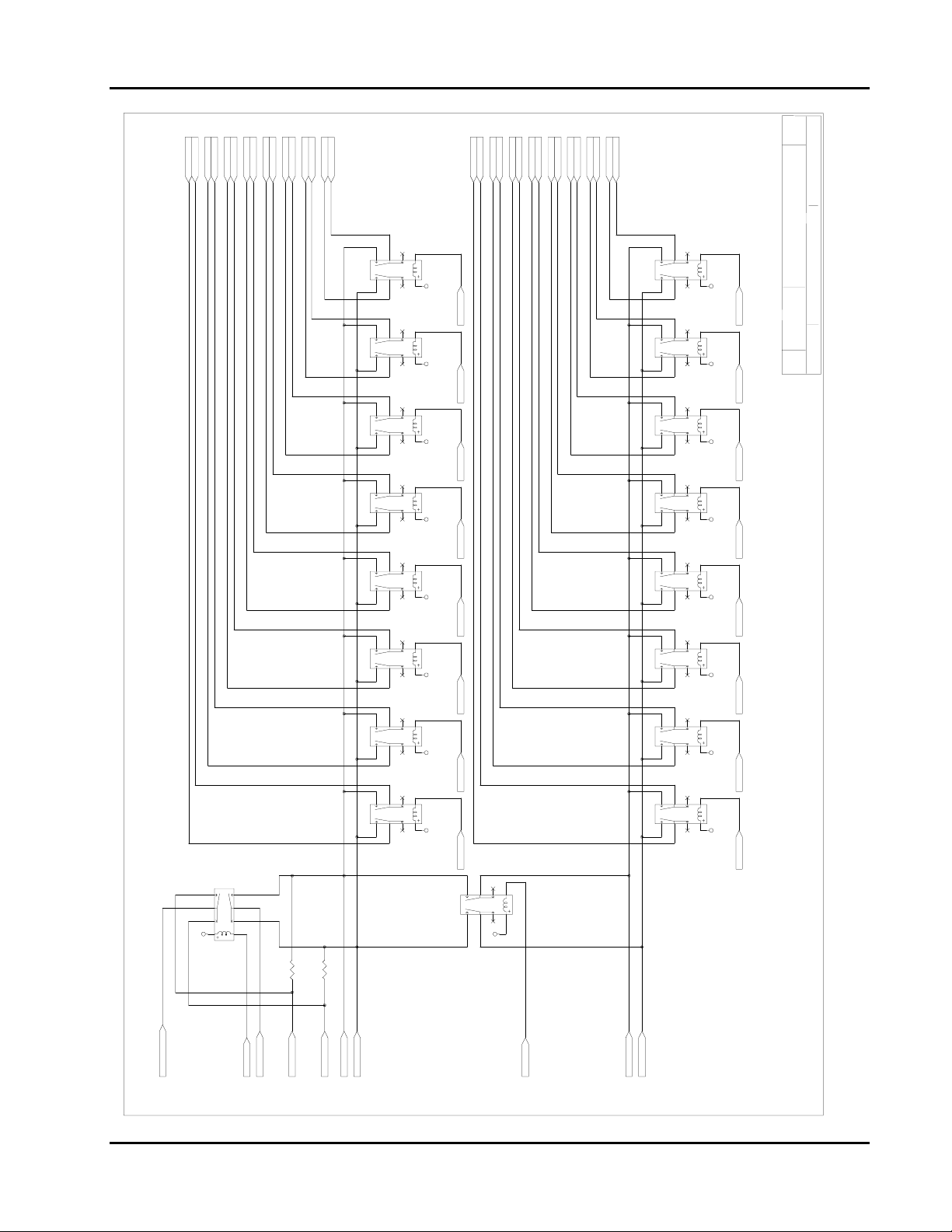
User Manual 1260-38
PG16
PG16
PG16
PG16
PG16
PG16
PG16
PG16CH0146H
CH0146H
CH0147H
CH0147L
CH0146L
CH0147H
CH0147L
CH0146L
PG16
CH0143H
CH0144H
CH0144L
CH0145L
CH0145H
CH0143H
CH0144L
CH0144H
CH0145H
CH0145L
PG16
PG16
PG16
PG16
PG16
PG16
PG16
CH0142L
CH0142H
CH0140H
CH0140L
CH0141L
CH0141H
CH0143L
PG16
PG16
PG16
PG16
PG16
PG16
PG16
PG16
PG16
PG16
PG16
PG16
PG16
PG16
PG16
PG16
CH0155L
CH0155H
CH0156H
CH0156L
CH0157L
CH0157H
CH0153L
CH0153H
CH0154H
CH0154L
CH0150H
CH0150L
CH0151L
CH0151H
CH0152L
CH0152H
SHEET 15 OF 2 3
CH0142L
CH0142H
CH0143L
CH0140L
CH0140H
CH0141H
CH0141L
9
10
K113
5 812 4
3
DR113
VRR
1
CH0155H
CH0155L
CH0156L
CH0156H
CH0157H
CH0157L
CH0153H
CH0153L
CH0154L
CH0154H
CH0150L
CH0150H
CH0151H
CH0151L
CH0152L
CH0152H
9
10
K121
5 812 4
3
DR121
VRR
1
12
9
10
K114
1
58
4
3
9
10
K115
1
5 812 4
3
9
10
K116
1
5 812 4
3
9
10
K117
1
5 812 4
3
9
10
K118
1
5 812 4
3
9
10
K119
1
5 812 4
3
DR113
DR114
VRR
DR114
PG21 PG21
DR115
DR115
DR116
VRR VRR
DR116
PG21 PG21
DR117
DR117
PG21
DR118
VRR VRR
DR118
DR119
9
K122
58
4
9
K123
5 812 4
9
K124
5 812 4
9
K125
5 812 4
9
K126
5 812 4
9
K127
5 812 4
PG22PG22
12
10
DR122
VRR
1
3
10
3
10
3
10
3
10
3
10
3
DR122
1
DR123
DR124
VRR VRR
1
DR124 DR121
PG22 PG22
DR125
1
DR125
PG22
DR126 DR123
VRR VRR
1
DR127
1
B 21 7 9 3 43 5 1 0 0 A
SCALE
SIZE C O DE ID ENT. N O. DOCU MENT NO. REV.
MULTIPLEXERS 14,15
DR119
9
10
K120
5 812 4
3
K158
81
43
91
0
15
2
VRR
R15
100
R16
100
COM14L
COM14H
COM141WR
PG16
DR158
COM14LR
COM141W
PG23
PG16
COM14HR
COM14L
COM14H
PG16
PG16
PG16
PG16
PG21 PG21
DR120
VRR VRR
1
DR120
PG21
9
10
K157
1
5 812 4
3
VRR
DR157
PG23
9
10
K128
1
5 812 4
3
COM15L
COM15H
COM15H
COM15L
PG16
PG16
Artisan Technology Group - Quality Instrumentation ... Guaranteed | (888) 88-SOURCE | www.artisantg.com
DR127
PG22 PG22PG22
DR128
VRR VRR
DR128 DR126
Drawings 4-19

User Manual 1260-38
PG15
PG15
PG15
PG15
PG14,15
PG14,15
COM14HR
COM15L
COM15H
PG14
PG14,15
PG14,15
PG13,14
PG13,14
PG14
PG14
PG14
PG13
PG13
PG13
PG13,14
COM13L
COM13H
COM14L
COM14H
COM12HR
COM141W
COM14LR
COM141WR
COM121W
COM12LR
COM121WR
PG13
PG13,14
PG12,13
PG12,13
PG12,13
PG12,13
PG11,12
PG12
PG12
PG12
PG12
PG11,12
PG11,12
PG11,12
COM08L
COM08H
COM09L
COM081W
COM08LR
COM08HR
COM101W
COM10LR
COM10HR
COM09H
COM10L
COM10H
COM11L
COM11H
COM12L
COM12H
COM101WR
COM081WR
SHEET 16 OF 23
1C2C3C4C5C6C7C8C9C
J201 ROWC
PG15
PG15
PG15
PG15
PG15
PG15
CH0145H
CH0151L
CH0151H
CH0155L
CH0155H
1B2B3B4B5B6B7B8B9B
J201 ROWB
PG15
PG15
PG15
PG15
PG15
PG15
CH0144H
CH0150L
CH0150H
CH0154L
CH0154H
1A2A3A4A5A6A7A8A9A
J201 ROWA
PG11
PG11
PG11
PG11
PG10,11
PG10,11
PG14
PG14
PG14
PG14
PG14
PG14
PG14
PG14
PG13
PG13
PG13
PG13
PG13
PG13
PG13
PG13
PG12
PG12
PG12
PG12
PG12
PG12
PG12
PG15
PG15
PG15
PG15
PG15
PG15
PG15
10C
11C
12C
13C
14C
15C
16C
17C
18C
19C
20C
21C
22C
23C
24C
25C
26C
27C
28C
29C
30C
31C
32C
5X32C
PG15
PG15
PG14
PG14
PG14
PG14
PG14
PG14
PG14
PG14
PG13
PG13
PG13
PG13
PG13
PG13
PG13
PG13
PG12
PG12
PG12
PG12
PG12
PG12
PG12
PG12
CH0131H
CH0135L
CH0135H
CH0141L
CH0141H
CH0145L
CH0131L
CH0115H
CH0121L
CH0121H
CH0125L
CH0125H
10B
11B
12B
13B
14B
15B
16B
17B
PG14
PG14
PG14
PG14
PG14
PG13
PG15
PG15
PG14
PG14
CH0134L
CH0134H
CH0140L
CH0140H
CH0144L
10A
PG10,11
PG10,11
PG9,10
PG9,10
PG13
PG14
CH0130H
CH0114H
CH0120L
CH0120H
CH0124L
CH0124H
CH0130L
11A
12A
13A
14A
15A
16A
17A
PG10
PG10
PG10
PG10
PG9,10
PG9,10
PG8,9
PG8,9
CH0095H
CH0101L
CH0101H
CH0105L
CH0105H
CH0111L
CH0111H
CH0115L
18B
19B
20B
21B
22B
23B
24B
25B
PG13
PG13
PG13
PG13
PG13
PG13
PG12PG8
CH0094H
CH0100L
CH0100H
CH0104L
CH0104H
CH0110L
CH0110H
CH0114L
18A
19A
20A
21A
22A
23A
24A
25A
PG9
PG9
PG9
PG9
PG8,9
PG8,9
CH0081L
CH0081H
CH0085L
CH0085H
CH0091L
CH0091H
CH0095L
26B
27B
28B
29B
30B
31B
32B
5X32B
PG12
PG12
PG12
PG12
PG12
PG12
PG12
CH0080H
CH0084L
CH0084H
CH0090L
CH0090H
CH0094L
CH0080L
26A
27A
28A
29A
30A
31A
32A
5X32A
PG8
PG8
PG8
PG8
PG8
PG8
PG8
J201 ROWE
PG15
J201 ROWD
PG15
CH0143L
CH0143H
CH0147L
CH0147H
CH0153L
CH0153H
CH0157L
CH0157H
1E2E3E4E5E6E7E8E9E
PG15
PG15
PG15
PG15
PG15
PG15
PG15
CH0142L
CH0142H
CH0146L
CH0146H
CH0152L
CH0152H
CH0156L
CH0156H1E
1D2D3D4D5D6D7D8D9D
CH0137H
10E
11E
12E
13E
14E
PG14
PG14
PG14
PG14
PG14
PG14
CH0126L
CH0126H
CH0132L
CH0132H
CH0136L
CH0136H
10D
11D
12D
13D
14D
CH0107H
CH0113L
CH0113H
CH0117L
CH0117H
15E
16E
17E
18E
19E
20E
21E
22E
23E
24E
PG13
PG13
PG13
PG14
PG14
PG13
CH0116H
CH0122L
CH0122H
15D
16D
17D
PG12
PG13
PG13
PG13
PG13
CH0102H
CH0106L
CH0102L
CH0106H
CH0112L
CH0112H
CH0116L
18D
19D
20D
21D
22D
23D
24D
CH0103L
CH0103H
CH0107L
CH0123L
CH0123H
CH0127L
CH0127H
CH0133L
CH0133H
CH0137L
PG12
CH0083L
CH0083H
CH0087L
CH0087H
CH0093L
CH0093H
CH0097L
CH0097H
25E
26E
27E
28E
29E
30E
31E
32E
5X32E
B 21793 435100 A
SCALE
SIZE C O D E ID ENT. NO. D OCUMENT NO. REV.
PG12
PG12
PG12
PG12
PG12
PG12
PG12
CH0082L
CH0082H
CH0086L
CH0086H
CH0092L
CH0092H
CH0096L
CH0096H
26D
27D
28D
29D
30D
31D
25D
32D
5X32D
J200 ROWC
J200 ROWB
J200 ROWA
Drawings 4-20
COM06H
COM07L
COM07H
COM061W
COM06LR
COM06HR
COM061WR
1C2C3C4C5C6C7C8C9C
PG11
PG11
PG11
PG11
PG11
PG11
PG11
CH0061H
CH0065L
CH0065H
CH0071L
CH0071H
CH0075L
CH0075H
2B3B4B5B6B7B8B
PG11
PG11
PG11
PG11
PG11
PG11
PG11
CH0060H
CH0064L
CH0064H
CH0070L
CH0070H
CH0074L
CH0074H 1B
1A2A3A4A5A6A7A8A9A
COM04L
COM04H
COM041W
COM04LR
COM05L
COM05H
COM06L
COM04HR
COM041WR
10C
11C
12C
13C
14C
15C
PG10
PG10
PG10
PG10
PG10
PG10
PG10
PG11
CH0051H
CH0055L
CH0055H
CH0061L
CH0045L
CH0045H
CH0051L
CH0041H
9B
10B
11B
12B
13B
14B
15B
PG10
PG10
PG10
PG11
PG10
PG10
PG10
PG10
CH0050H
CH0054L
CH0054H
CH0060L
CH0040H
CH0044L
CH0044H
CH0050L
10A
11A
12A
13A
14A
15A
COM021W
COM02LR
COM02HR
COM01H
COM02L
COM02H
COM03L
COM03H
COM021WR
16C
17C
18C
19C
20C
21C
22C
23C
24C
25C
PG8
PG9
PG9
PG9
PG9
PG9
PG9
PG9
PG9
PG10
CH0015H
CH0021L
CH0021H
CH0025L
CH0025H
CH0031L
CH0031H
CH0035L
CH0035H
CH0041L
16B
17B
18B
19B
20B
21B
22B
23B
24B
25B
PG8
PG9
PG9
PG9
PG9
PG9
PG9
PG9
PG9
PG10
CH0014H
CH0020L
CH0020H
CH0024L
CH0024H
CH0030L
CH0030H
CH0034L
CH0034H
CH0040L
16A
17A
18A
19A
20A
21A
22A
23A
24A
25A
COM00L
COM00H
COM01L
COM001W
COM00LR
COM00HR
COM001WR
26C
27C
28C
29C
30C
31C
32C
5X32C
PG8
PG8
PG8
PG8
PG8
PG8
PG8
CH0001H
CH0005L
CH0005H
CH0011L
CH0011H
CH0015L
CH0001L
26B
27B
28B
29B
30B
31B
32B
5X32B
PG8
PG8
PG8
PG8
PG8
PG8
PG8
CH0004L
CH0004H
CH0010L
CH0010H
CH0014L
CH0000L
CH0000H
26A
27A
28A
29A
30A
31A
32A
5X32A
PG11
PG11
PG11
PG11
PG11
CH0073L
CH0073H
CH0077L
CH0077H
2E3E4E5E6E7E8E
J200 ROWE
PG11
PG11
PG11
PG11
PG11
CH0072L
CH0072H
CH0076L
CH0076H
1D2D3D4D5D6D7D8D9D
J200 ROWD
PG11
PG11
PG11
PG10
PG10
PG10
PG10
PG10
PG10
PG10
PG10
PG9
PG9
PG9
PG9
PG9
PG9
PG9
PG9
PG8
PG8
PG8
PG8
PG8
PG8
PG8
PG8
CH0063L
CH0063H
CH0067L
CH0067H
CH0057L
CH0057H
CH0037H
CH0043L
CH0043H
CH0047L
CH0047H
CH0053L
CH0053H
CH0017H
CH0023L
CH0023H
CH0027H
CH0033L
CH0033H
CH0037L
CH0027L
CH0003L
CH0003H
CH0007L
CH0007H
CH0013L
CH0013H
CH0017L
FRONT PANEL CONNECTORS
9E
10E
11E
12E
13E
14E
15E
16E
17E
18E
19E
20E
21E
22E
23E
24E
25E
26E
27E
28E
29E
30E
31E
32E
5X32E
PG10
PG10
PG10
PG10
PG10
PG10
PG10
PG10
PG9
PG9
PG9
PG9
PG11
PG11
PG11
CH0046H
CH0052L
CH0052H
CH0056L
CH0056H
CH0062L
CH0062H
CH0066L
CH0066H
10D
11D
12D
13D
PG9
PG9
PG9
PG9
PG8
PG8
PG8
PG8
PG8
PG8
PG8
PG8
CH0036H
CH0042L
CH0042H
CH0046L
14D
CH0026H
CH0032L
CH0032H
CH0036L
CH0016H
CH0022L
CH0022H
CH0026L
15D
16D
17D
18D
19D
20D
21D
22D
23D
24D
25D
CH0002L
CH0002H
CH0006L
CH0006H
CH0012L
CH0012H
CH0016L
26D
27D
28D
29D
30D
31D
32D
5X32D
Artisan Technology Group - Quality Instrumentation ... Guaranteed | (888) 88-SOURCE | www.artisantg.com

User Manual 1260-38
SER
U2
1A 2B 3C 4D 5E 10F 11G 12H 14
PG8
PG8
DR1
DR2
DR1
DR2
SRO0
SRO1
SRO2
SH E E T 17 O F 23
SRO0 PG3
13
QH
PG8
PG8
PG8
DR5
DR6
DR5
DR6
DR7
SER
U4
1A 2B 3C 4D 5E 10F 11G 12H 14
PG8
DR7
DR8
DR8
CLK
INH
SH/LD
CLR
74HCT166
7
6
15
9
215Z2B 47K
116Z2A 47K
314Z2C 47K
512Z2E 47K
413Z2D 47K
611Z2F 47K
710Z2G 47K
89Z2H 47K
PG8
PG8
DR4
DR3
314Z1C 220K
215Z1B 220K
413Z1D 220K
512Z1E 220K
611Z1F 220K
710Z1G 220K
116
Z1A 220K
DR4
DR3
89Z1H 220K
SRO1 PG3
13
QH
CLK
INH
SH/LD
CLR
74HCT166
7
6
15
9
413Z4D 47K
512Z4E 47K
611Z4F 47K
710Z4G 47K
215Z4B 47K
314
Z4C 47K
215Z3B 220K
314Z3C 220K
413Z3D 220K
89Z4H 47K
512Z3E 220K
611Z3F 220K
710Z3G 220K
89Z3H 220K
116Z4A 47K
PG8
PG8
PG8
PG8
DR9
DR10
DR11
DR12
116Z3A 220K
DR9
DR11
DR10
DR12
PG8
PG8
PG8
DR13
DR14
DR15
DR13
DR14
DR15
SER
U6
1A 2B 3C 4D 5E 10F 11G 12H 14
PG8
DR16
DR16
SRO2 PG3
13
QH
CLK
INH
SH/LD
CLR
74HCT166
7
6
15
9
B 2 17 9 3 435100 A
SCALE
SIZE CO D E IDEN T. NO . DO C U ME N T N O. RE V.
710Z6G 47K
116Z6A 47K
PG9
PG9
PG9
PG9
DR20
DR17
DR18
DR19
116Z5A 220K
DR20
DR17
DR18
DR19
89Z6H 47K
215Z6B 47K
314Z6C 47K
413Z6D 47K
512Z6E 47K
611
Z6F 47K
PG9
PG9
PG9
PG9
DR21
DR22
DR23
DR24
215Z5B 220K
314Z5C 220K
413Z5D 220K
512Z5E 220K
611Z5F 220K
710Z5G 220K
89Z5H 220K
DR21
DR22
DR23
DR24
VRR
OUT125OUT224OUT323OUT422OUT521OUT620OUT719OUT8
VCCSTROBE0
18
16
15
NC
COM17VDD27GND
OUT125OUT224OUT323OUT422OUT521OUT620OUT719OUT8
VRR
VCCSTROBE1
18
16
15
NC
COM17VDD27GND
OUT125OUT224OUT323OUT422OUT521OUT620OUT719OUT8
VRR
VCC
18
16
15
NC
COM17VDD27GND
RELAY DRIVERS 1 - 24
IN1
IN2
IN3
IN4
IN5
IN6
IN7
IN8
STR
CLR
U1
5
6
7
8
9
LD0
LD1
LD2
LD3
LD4
LD[0..7]
LD[0..7]
PG2
OE
5801BV
10
11
12
3
1
28
LD5
LD6
LD7
PG2
IN1
IN2
IN3
IN4
IN5
IN6
IN7
IN8
STR
CLR
U3
5
6
7
8
9
LD0
LD1
LD2
LD3
LD4
OE
5801BV
10
11
12
3
1
28
LD5
LD6
LD7
PG2
IN1
IN2
IN3
IN4
IN5
IN6
IN7
IN8
STR
CLR
U5
5
6
7
8
9
LD0
LD1
LD2
LD3
LD4
OE
5801BV
10
11
12
3
1
28
LD5
LD6
LD7
RESET\
CLKOUT
SH/LD\
RESET\
CLKOUT
RESET
STROBE2
PG2
PG2
SH/LD\
PG2
PG2
PG2
Drawings 4-21
Artisan Technology Group - Quality Instrumentation ... Guaranteed | (888) 88-SOURCE | www.artisantg.com

User Manual 1260-38
SER
U8
1A 2B 3C 4D 5E 10F 11G 12H 14
PG9
PG9
DR25
DR25
DR26
SRO3
SRO4
SRO5
SHE E T 18 O F 23
SRO3 PG3
13
QH
CLK
INH
SH/LD
CLR
74HCT166
7
6
15
9
116Z8A 47K
215Z8B 47K
314Z8C 47K
413Z8D 47K
512Z8E 47K
611Z8F 47K
710Z8G 47K
89Z8H 47K
PG9
PG9
DR26
DR27
DR28
215Z7B 220K
314Z7C 220K
413Z7D 220K
512Z7E 220K
611Z7F 220K
710Z7G 220K
116Z7A 220K
DR27
DR28
89
Z7H 220K
PG9
PG9
PG9
DR29
DR30
DR29
DR30
DR31
SER
U10
1A 2B 3C 4D 5E 10F 11G 12H 14
PG9
DR31
DR32
DR32
SRO4 PG3
13
QH
CLK
INH
SH/LD
CLR
74HCT166
7
6
15
9
116Z10A 47K
215
314Z10C 47K
413Z10D 47K
512Z10E 47K
611Z10F 47K
710Z10G 47K
89Z10H 47K
Z10B 47K
PG10
PG10
PG10
PG10
DR33
DR34
DR35
DR36
116Z9A 220K
215Z9B 220K
314Z9C 220K
413Z9D 220K
512Z9E 220K
611Z9F 220K
710Z9G 220K
89Z9H 220K
DR35
DR36
DR33
DR34
PG10
PG10
PG10
DR37
DR38
DR37
DR38
DR39
SER
U12
1A 2B 3C 4D 5E 10F 11G 12H 14
PG10
DR39
DR40
DR40
SRO5 PG3
13
QH
CLK
INH
SH/LD
CLR
74HCT166
7
6
15
9
B 21793 435100 A
SCALE
SIZE CO D E IDEN T. NO. D O CUM E N T N O . REV.
116Z12A 47K
215Z12B 47K
314Z12C 47K
413
512Z12E 47K
611Z12F 47K
710Z12G 47K
89Z12H 47K
Z12D 47K
PG10
PG10
PG10
PG10
PG10
PG10
DR44
DR41
DR42
DR43
116Z11A 220K
215Z11B 220K
314Z11C 220K
413Z11D 220K
512Z11E 220K
611Z11F 220K
DR41
DR42
DR43
DR44
PG10
PG10
DR45
DR46
DR47
DR48
710Z11G 220K
89Z11H 220K
DR45
DR46
DR47
DR48
VCC
VRR
16
15
18
NC
OUT125OUT224OUT323OUT422OUT521OUT620OUT719OUT8
IN1
IN2
IN3
IN4
U7
5
6
7
8
LD0
LD1
LD2
LD3
LD[0..7]PG2
LD[0..7]
COM17VDD27GND
IN5
9
LD4
OE
IN6
IN7
IN8
STR
CLR
5801BV
28
10
11
12
3
1
LD5
LD6
LD7
STROBE3
PG2
OUT125OUT224OUT323OUT422OUT521OUT620OUT719OUT8
IN1
IN2
U9
5
6
LD0
LD1
IN3
7
LD2
VCC
VRR
16
15
18
NC
COM17VDD27GND
IN4
IN5
8
9
LD3
LD4
OE
IN6
IN7
IN8
STR
CLR
5801BV
28
10
11
12
3
1
LD5
LD6
LD7
STROBE4
PG2
OUT125OUT224OUT323OUT422OUT521OUT620OUT719OUT8
IN1
IN2
U11
5
6
LD0
LD1
IN3
7
LD2
VCC
VRR
16
15
18
NC
COM17VDD27GND
IN4
IN5
8
9
LD3
LD4
OE
IN6
IN7
IN8
STR
CLR
5801BV
28
10
11
12
3
1
LD5
LD6
LD7
RESET\
CLKOUT
SH/LD\
RESET\
CLKOUT
RESET
STROBE5
PG2
PG2
SH/LD\
PG2
PG2
PG2
RELAY DRIVERS 25 - 48
Drawings 4-22
Artisan Technology Group - Quality Instrumentation ... Guaranteed | (888) 88-SOURCE | www.artisantg.com

User Manual 1260-38
SER
U14
1A 2B 3C 4D 5E 10F 11G 12H 14
PG11DR49
DR49
SRO6
SRO6 PG3
13
QH
CLK
INH
SH/LD
CLR
74HCT166
7
6
15
9
116Z14A 47K
215Z14B 47K
314Z14C 47K
413Z14D 47K
512Z14E 47K
611Z14F 47K
710Z14G 47K
89Z14H 47K
PG11
PG11
PG11
DR50
DR51
DR52
116Z13A 220K
215Z13B 220K
314Z13C 220K
413Z13D 220K
512Z13E 220K
611Z13F 220K
89Z13H 220K
710
DR50
DR51
DR52
Z13G 220K
PG11
PG11
PG11
DR53
DR54
DR53
DR54
DR55
SER
U16
1A 2B 3C 4D 5E 10F 11G 12H 14
PG11
DR55
DR56
DR56
SRO7
SRO7 PG3
13
QH
CLK
INH
SH/LD
CLR
74HCT166
7
6
15
9
413Z16D 47K
512Z16E 47K
611Z16F 47K
710Z16G 47K
215Z16B 47K
314
Z16C 47K
215Z15B 220K
314Z15C 220K
413Z15D 220K
89Z16H 47K
512Z15E 220K
611Z15F 220K
710Z15G 220K
89Z15H 220K
116Z16A 47K
PG11
PG11
PG11
PG11
DR57
DR58
DR59
DR60
116Z15A 220K
DR57
DR59
DR60
DR58
PG11
PG11
PG11
DR61
DR62
DR61
DR62
DR63
SER
U18
1A 2B 3C 4D 5E 10F 11G 12H 14
PG11
DR64
DR63
DR64
SRO8
SRO8 PG3
13
QH
CLK
INH
SH/LD
CLR
74HCT166
7
6
15
9
710Z18G 47K
116Z18A 47K
PG12
PG12
PG12
PG12
DR65
DR66
DR67
DR68
116Z17A 220K
DR65
DR66
DR67
DR68
89Z18H 47K
215Z18B 47K
314Z18C 47K
413Z18D 47K
512Z18E 47K
611
Z18F 47K
PG12
PG12
PG12
PG12
DR69
DR70
DR71
DR72
215Z17B 220K
314Z17C 220K
413Z17D 220K
512Z17E 220K
611Z17F 220K
710Z17G 220K
89Z17H 220K
DR69
DR70
DR71
DR72
SHE ET 1 9 O F 23
B 21793 435100 A
SCALE
SIZE C O DE ID E N T. NO . DO C UM E N T N O. REV.
VRR
VCC
16
15
18
NC
OUT125OUT224OUT323OUT422OUT521OUT620OUT719OUT8
IN1
IN2
IN3
IN4
U13
5
6
7
8
LD0
LD1
LD2
LD3
LD[0..7]PG2
LD[0..7]
COM17VDD27GND
IN5
9
LD4
OE
IN6
IN7
IN8
STR
CLR
5801BV
28
10
11
12
3
1
LD7
LD5
LD6
STROBE6
PG2
OUT125OUT224OUT323OUT422OUT521OUT620OUT719OUT8
IN1
U15
5
6
LD0
LD1
IN2
IN3
IN4
7
8
LD2
LD3
VRR
VCC
16
15
18
NC
COM17VDD27GND
IN5
9
LD4
OE
IN6
IN7
IN8
STR
CLR
5801BV
28
10
11
12
3
1
LD7
LD5
LD6
STROBE7
PG2
OUT125OUT224OUT323OUT422OUT521OUT620OUT719OUT8
IN1
IN2
U17
5
6
LD0
LD1
IN3
IN4
7
8
LD2
LD3
VRR
VCC
16
15
18
NC
COM17VDD27GND
IN5
9
LD4
OE
IN6
IN7
IN8
STR
CLR
5801BV
28
10
11
12
3
1
LD7
LD5
LD6
RESET\
CLKOUT
SH/LD\
RESET\
CLKOUT
RESET
STROBE8
PG2
PG2
SH/LD\
PG2
PG2
PG2
RELAY DRIVERS 49 - 72
Drawings 4-23
Artisan Technology Group - Quality Instrumentation ... Guaranteed | (888) 88-SOURCE | www.artisantg.com

User Manual 1260-38
PG3
SER
U20
1A 2B 3C 4D 5E 10F 11G 12H 14
PG12DR73
PG12
DR74
DR73
DR74
SRO9
SRO10
SRO11
SHEET 20 OF 23
SRO9
13
QH
CLK
INH
SH/LD
CLR
74HCT166
7
6
15
9
116Z20A 47K
215Z20B 47K
314Z20C 47K
413Z20D 47K
512Z20E 47K
611Z20F 47K
710Z20G 47K
89Z20H 47K
PG12
PG12
DR75
DR76
116Z19A 220K
215Z19B 220K
314Z19C 220K
413Z19D 220K
512Z19E 220K
611Z19F 220K
710Z19G 220K
89Z19H 220K
DR75
DR76
PG12
PG12
PG12
DR77
DR78
DR77
DR78
DR79
SER
U22
1A 2B 3C 4D 5E 10F 11G 12H 14
PG12
DR79
DR80
DR80
SRO10 PG3
13
QH
CLK
INH
SH/LD
CLR
74HCT166
7
6
15
9
413Z22D 47K
512Z22E 47K
611Z22F 47K
710Z22G 47K
215Z22B 47K
314
Z22C 47K
215Z21B 220K
314Z21C 220K
413Z21D 220K
89Z22H 47K
512Z21E 220K
611Z21F 220K
710Z21G 220K
89Z21H 220K
116Z22A 47K
PG13
PG13
PG13
PG13
DR82
DR83
DR84
DR81
116Z21A 220K
DR83
DR84
DR82
DR81
PG13
PG13
PG13
DR85
DR86
DR85
DR86
DR87
SER
U24
1A 2B 3C 4D 5E 10F 11G 12H 14
PG13
DR87
DR88
DR88
SRO11 PG3
13
QH
CLK
INH
SH/LD
CLR
74HCT166
7
6
15
9
B 21793 435100 A
SCALE
SIZ E CO DE ID E NT. NO. DOCU ME NT NO . R EV.
710Z24G 47K
116Z24A 47K
PG13
PG13
PG13
PG13
DR90
DR91
DR92
DR89
116Z23A 220K
DR90
DR91
DR92
DR89
89Z24H 47K
215Z24B 47K
314Z24C 47K
413Z24D 47K
512Z24E 47K
611
Z24F 47K
PG13
PG13
PG13
PG13
DR93
DR94
DR95
DR96
215Z23B 220K
314Z23C 220K
413Z23D 220K
512Z23E 220K
611Z23F 220K
710Z23G 220K
89Z23H 220K
DR93
DR94
DR95
DR96
VRR
VCC
16
15
18
NC
OUT125OUT224OUT323OUT422OUT521OUT620OUT719OUT8
IN1
IN2
IN3
IN4
U19
5
6
7
8
LD0
LD1
LD2
LD3
LD[0..7]PG2
LD[0..7]
COM17VDD27GND
IN5
9
LD4
OE
IN6
IN7
IN8
STR
CLR
5801BV
28
10
11
12
3
1
LD7
LD5
LD6
STROBE9
PG2
OUT125OUT224OUT323OUT422OUT521OUT620OUT719OUT8
IN1
IN2
U21
5
6
LD0
LD1
IN3
IN4
7
8
LD2
LD3
VRR
VCC
18
16
15
NC
COM17VDD27GND
IN5
IN6
IN7
IN8
STR
CLR
OE
5801BV
9
10
11
12
3
1
28
LD4
LD5
LD6
LD7
STROBE10
PG2
OUT125OUT224OUT323OUT422OUT521OUT620OUT719OUT8
IN1
U23
5
6
LD0
LD1
IN2
IN3
IN4
7
8
LD2
LD3
VRR
VCC
18
16
15
NC
COM17VDD27GND
IN5
IN6
IN7
IN8
STR
CLR
OE
5801BV
9
10
11
12
3
1
28
LD4
LD5
LD6
LD7
RESET\
CLKOUT
SH/LD\
RESET\
CLKOUT
RESET
STROBE11
PG2
PG2
SH/LD\
PG2
PG2
PG2
RELAY DRIVERS 73 - 96
Drawings 4-24
Artisan Technology Group - Quality Instrumentation ... Guaranteed | (888) 88-SOURCE | www.artisantg.com

User Manual 1260-38
PG3
SER
U26
1A 2B 3C 4D 5E 10F 11G 12H 14
PG14DR97
DR97
SRO12
SRO12 PG3
13
QH
CLK
INH
SH/LD
CLR
74HCT166
7
6
15
9
116Z26A 47K
215Z26B 47K
314Z26C 47K
413Z26D 47K
512Z26E 47K
611Z26F 47K
710Z26G 47K
89Z26H 47K
PG14
PG14
PG14
DR98
DR99
DR100
116Z25A 220K
215Z25B 220K
314Z25C 220K
413Z25D 220K
512Z25E 220K
611Z25F 220K
710Z25G 220K
89
DR98
DR99
DR100
Z25H 220K
PG14
PG14
PG14
DR101
DR102
DR101
DR102
DR103
SER
U28
1A 2B 3C 4D 5E 10F 11G 12H 14
PG14
DR103
DR104
DR104
SRO13
SRO13 PG3
13
QH
CLK
INH
SH/LD
CLR
74HCT166
7
6
15
9
413Z28D 47K
512Z28E 47K
611Z28F 47K
710Z28G 47K
215Z28B 47K
314
Z28C 47K
215Z27B 220K
314Z27C 220K
413Z27D 220K
89Z28H 47K
512Z27E 220K
611Z27F 220K
710Z27G 220K
89Z27H 220K
116Z28A 47K
PG14
PG14
PG14
PG14
DR106
DR107
DR108
DR105
116Z27A 220K
DR106
DR107
DR108
DR105
PG14
PG14
PG14
DR109
DR110
DR111
DR109
DR110
DR111
SER
U30
1A 2B 3C 4D 5E 10F 11G 12H 14
PG14
DR112
DR112
SRO14
SRO14
13
QH
CLK
INH
SH/LD
CLR
74HCT166
7
6
15
9
710Z30G 47K
116Z30A 47K
PG15
PG15
PG15
PG15
DR114
DR115
DR116
DR113
116Z29A 220K
DR114
DR115
DR116
DR113
89Z30H 47K
215Z30B 47K
314Z30C 47K
413Z30D 47K
512Z30E 47K
611
Z30F 47K
PG15
PG15
PG15
PG15
DR117
DR118
DR119
DR120
215Z29B 220K
314Z29C 220K
413Z29D 220K
512Z29E 220K
611Z29F 220K
710Z29G 220K
89Z29H 220K
DR117
DR118
DR119
DR120
SHEET 21 OF 23
B 217 9 3 4351 0 0 A
SCALE
SIZ E C O D E ID EN T. N O . D O CU M EN T N O . R E V.
VRR
VCC
16
15
18
NC
OUT125OUT224OUT323OUT422OUT521OUT620OUT719OUT8
IN1
IN2
IN3
IN4
U25
5
6
7
8
LD0
LD1
LD2
LD3
LD[0..7]PG2
LD[0..7]
COM17VDD27GND
IN5
IN6
IN7
IN8
OE
STR
CLR
5801BV
9
10
11
12
28
3
1
LD4
LD5
LD6
LD7
STROBE12
PG2
OUT125OUT224OUT323OUT422OUT521OUT620OUT719OUT8
IN1
U27
5
6
LD0
LD1
IN2
IN3
IN4
7
8
LD2
LD3
VRR
VCC
16
15
18
NC
COM17VDD27GND
IN5
IN6
IN7
IN8
OE
STR
CLR
5801BV
9
10
11
12
28
3
1
LD4
LD5
LD6
LD7
STROBE13
PG2
OUT125OUT224OUT323OUT422OUT521OUT620OUT719OUT8
IN1
U29
5
LD0
IN2
IN3
IN4
6
7
8
LD1
LD2
LD3
VRR
VCC
16
15
18
NC
COM17VDD27GND
IN5
IN6
IN7
IN8
OE
STR
CLR
5801BV
9
10
11
12
28
3
1
LD4
LD5
LD6
LD7
RESET\
CLKOUT
SH/LD\
RESET\
CLKOUT
RESET
STROBE14
PG2
PG2
SH/LD\
PG2
PG2
PG2
RELAY DRIVERS 97 - 120
Drawings 4-25
Artisan Technology Group - Quality Instrumentation ... Guaranteed | (888) 88-SOURCE | www.artisantg.com

User Manual 1260-38
SER
U32
1A 2B 3C 4D 5E 10F 11G 12H 14
PG15DR121
PG15
DR121
DR122
DR122
PG3
SRO15
SRO15
13
QH
CLK
INH
SH/LD
CLR
74HCT166
7
6
15
9
116Z32A 47K
215Z32B 47K
314Z32C 47K
413Z32D 47K
512Z32E 47K
611Z32F 47K
710Z32G 47K
89Z32H 47K
PG15
PG15
DR124
DR123
116Z31A 220K
215Z31B 220K
314Z31C 220K
413Z31D 220K
512Z31E 220K
611Z31F 220K
710Z31G 220K
89Z31H 220K
DR123
DR124
PG15
PG15
PG15
DR125
DR126
DR127
DR125
DR126
DR127
SER
U34
1A 2B 3C 4D 5E 10F 11G 12H 14
PG15
DR128
DR128
SRO16
SRO16 PG3
13
QH
CLK
INH
SH/LD
CLR
74HCT166
7
6
15
9
413Z34D 47K
512Z34E 47K
611Z34F 47K
710Z34G 47K
215Z34B 47K
314
Z34C 47K
215Z33B 220K
314Z33C 220K
413Z33D 220K
89Z34H 47K
512Z33E 220K
611Z33F 220K
710Z33G 220K
89Z33H 220K
116Z34A 47K
PG8
PG8
PG8
PG8
DR129
DR130
DR131
DR132
116Z33A 220K
DR129
DR130
DR131
DR132
PG9
PG9
PG9
DR133
DR134
DR133
DR134
DR135
SER
U36
1A 2B 3C 4D 5E 10F 11G 12H 14
PG9
DR135
DR136
DR136
PG3
SRO17
SRO17
13
QH
CLK
INH
SH/LD
CLR
74HCT166
7
6
15
9
710Z36G 47K
116Z36A 47K
PG10
PG10
PG10
PG10
DR137
DR138
DR139
DR140
116Z35A 220K
DR137
DR138
DR139
DR140
89Z36H 47K
215Z36B 47K
314Z36C 47K
413Z36D 47K
512Z36E 47K
611
Z36F 47K
PG11
PG11
PG11
PG11
DR141
DR142
DR143
DR144
215Z35B 220K
314Z35C 220K
413Z35D 220K
512Z35E 220K
611Z35F 220K
710Z35G 220K
89Z35H 220K
DR141
DR142
DR143
DR144
SHEET 22 OF 23
B 2 1 7 9 3 4 3 5 1 0 0 A
SCALE
SIZ E C O DE ID EN T. NO . DO CU ME N T N O. RE V.
VRR
VCC
18
16
15
NC
OUT125OUT224OUT323OUT422OUT521OUT620OUT719OUT8
IN1
IN2
IN3
IN4
U31
5
6
7
8
LD0
LD1
LD2
LD3
LD[0..7]PG2
LD[0..7]
COM17VDD27GND
IN5
IN6
IN7
IN8
OE
STR
CLR
5801BV
9
10
11
12
28
3
1
LD4
LD5
LD6
LD7
STROBE15
PG2
OUT125OUT224OUT323OUT422OUT521OUT620OUT719OUT8
IN1
U33
5
6
LD0
LD1
IN2
IN3
IN4
7
8
LD2
LD3
VRR
VCC
18
16
15
NC
COM17VDD27GND
IN5
IN6
IN7
IN8
OE
STR
CLR
5801BV
9
10
11
12
28
3
1
LD4
LD5
LD6
LD7
STROBE16
PG2
OUT125OUT224OUT323OUT422OUT521OUT620OUT719OUT8
IN1
U35
5
6
LD0
LD1
IN2
IN3
IN4
7
8
LD2
LD3
VRR
VCC
18
16
15
NC
COM17VDD27GND
IN5
IN6
IN7
IN8
OE
STR
CLR
5801BV
9
10
11
12
28
3
1
LD4
LD5
LD6
LD7
RESET\
CLKOUT
SH/LD\
RESET\
RESET
STROBE17
PG2
PG2
CLKOUT
PG2
PG2
PG2
RELAY DRIVERS 121 - 144
SH/LD\
Drawings 4-26
Artisan Technology Group - Quality Instrumentation ... Guaranteed | (888) 88-SOURCE | www.artisantg.com

User Manual 1260-38
PG3
SER
U38
1A 2B 3C 4D 5E 10F 11G 12H 14
PG12
PG12
DR145
DR145
DR146
SRO18
SRO19
SHEET 23 OF 23
SRO18
13
QH
PG13
PG13
PG13
DR149
DR150
DR149
DR150
DR151
SER
U40
1A 2B 3C 4D 5E 10F 11G 12H 14
PG13
DR151
DR152
DR152
CLK
INH
SH/LD
CLR
74HCT166
7
6
15
9
116Z38A 47K
215Z38B 47K
314Z38C 47K
413Z38D 47K
512Z38E 47K
611Z38F 47K
710Z38G 47K
89Z38H 47K
PG12
PG12
DR148
DR146
DR147
314Z37C 220K
413Z37D 220K
611Z37F 220K
215Z37B 220K
512Z37E 220K
710Z37G 220K
116
Z37A 220K
DR148
DR147
89Z37H 220K
SRO19 PG3
13
QH
CLK
INH
SH/LD
CLR
74HCT166
7
6
15
9
B 21793 435100 A
SCALE
SIZ E C O DE ID E NT. NO . D O CU MEN T N O . R E V.
116Z40A 47K
215Z40B 47K
314Z40C 47K
413Z40D 47K
512Z40E 47K
611Z40F 47K
710Z40G 47K
89Z40H 47K
PG14
PG14
PG14
PG14
DR153
DR154
DR155
DR156
512Z39E 220K
116Z39A 220K
215Z39B 220K
314Z39C 220K
413
DR153
DR154
DR155
DR156
Z39D 220K
PG15
PG15
DR157
DR158
611Z39F 220K
710Z39G 220K
89Z39H 220K
DR157
DR158
VCC
VRR
16
15
18
NC
OUT125OUT224OUT323OUT422OUT521OUT620OUT719OUT8
IN1
IN2
IN3
IN4
U37
5
6
7
8
LD0
LD1
LD2
LD3
LD[0..7]
PG2 LD[0..7]
COM17VDD27GND
IN5
9
LD4
OE
IN6
IN7
IN8
STR
CLR
5801BV
28
10
11
12
3
1
LD5
LD6
LD7
STROBE18
PG2
OUT125OUT224OUT323OUT422OUT521OUT620OUT719OUT8
IN1
U39
5
6
LD0
LD1
IN2
IN3
7
LD2
VCC
VRR
16
15
18
NC
COM17VDD27GND
RELAY DRIVERS 145 - 158
IN4
IN5
8
9
LD3
LD4
OE
IN6
IN7
IN8
STR
CLR
5801BV
28
10
11
12
3
1
LD5
LD6
LD7
RESET\
CLKOUT
SH/LD\
STROBE19
RESET
PG2
RESET\
CLKOUT
SH/LD\
PG2
PG2
PG2
Drawings 4-27
Artisan Technology Group - Quality Instrumentation ... Guaranteed | (888) 88-SOURCE | www.artisantg.com

User Manual 1260-38
REV.SH.
DWG. NO.
B
REVISIONS
1
407407,-001
3
45
D
APPROVEDDATE
AMN 09/21/98
DESCRIPTION
AA
C
2 PLCS
15
B
5
A
B
3
OFSCALE
12:1
17
SHEET
CALC.WT ACT.WT
980346 REV. F
407407,-001
DWG NO. REV.
160 PIN CONN KIT
W/BACKSHELL
CAGE CODE
4 Goodyear St.,Irvine,CA.92718-2002
TITLE
SIZE
234
REVISED PER EO NO.
REVISED PER EO NO.
REVISED PER EO NO.
REVISED PER EO NO.
RELEASED PER DRN NO. 1557 3/18/96 db
A
REV
ZONE
REVISED PER EO NO.
REVISED PER EO NO. 25106
B
4 7 6
16
11
12
160 PLCS
10
2 PLCS
PIN a-1
(SHOWING CONNECTOR
ONLY)
FRONT VIEW
PIN e-32
11( )
568
( )
1516
68 1
7
PROPRIETARY NOTICE
(26-20G CRIMPS)
407407-001: 160 PIN CONN KIT W/BACKSHELL
BAG AND TAG A LL ITEM S, INCLUDING INSTR U C T ION
SHEET, WITH RACAL INSTRUMENTS PART NO. AND
THIS DOCUMENT AND THE TEC HN IC AL DATA HEREON DISCLOSED ARE PROPRI E TAR Y
TO RACAL INSTRUMENTS INC. AND SHALL NOT, WITHOUT THE EXPRESS WRITTEN
PERMISSION OF RACAL INSTRUMENTS INC. BE USED, RELEASED OR DISCLOSED
IN WHOLE OR IN PART, OR USED TO SOLICIT Q UOTATION FROM A COMPETIT IVE
SOURCE OR USED FOR MANUFAC TURE BY ANYONE OTHER THAN RACAL INSTRUM ENTS
INC. THE INFORMATION HEREON HAS BEEN DEVELOPED AT PRIVATE EXPENSE,
1.
AND MAY ONLY BE USED FOR PURPOSES OF ENGINEERING EVALUATION AND FOR
INCORPORATION INTO TECHNICA L SPE CI FICA TIO N S AND OTHER DO CUME NT S WHICH
SPECIFY PROCUREMENT OF PRODUCTS FROM RACA L INSTRUMENTS INC.
NOTES:
D
(28-24G CRIMPS)
CURRENT REVISION LETTER.
2. 407407: 160 PIN CONN KIT W/BACKSHELL
C
2 PLCS
2020
710
( )( )
B
4( )
( ) ( )
VIEW A-A
11 6
( )
A
Drawings 4-28
Artisan Technology Group - Quality Instrumentation ... Guaranteed | (888) 88-SOURCE | www.artisantg.com

User Manual 1260-38
D
APPROVED
3/18/96 db
134
AMN 09/16/98
REVISIONS
2 PLCS
20
1
REVISED PE R E O N O. 24393
REVISED PE R E O N O.
REVISED PE R E O N O.
RELEASED PER DRN NO. 1557
A
B
REV DESCRIPTION DATE
ZONE
( ) 7
10
( )
6
( )
C
PIN a-1
15
( )
4( )
16
VIEW A-A
(CABLE NOT SHOWN)
( )
11
( )
2
2 PLCS
A/R
24
22
4
DWG. NO.
407408
407408 REV.---
CABLE 1
2 PLCS
18
407408 REV.---
CABLE 2
REV.SH.
1
B
PIN e-32
A
B
18
1
ACT.WTCALC.WT
407408
DWG NO. REV.
1
CAGE CODE
4 Goodyear St.,Irvine,CA.92718-2002
1/1
TITLE
160 PIN CABLE ASSY, 6FT 24G
SIZE
SCALE SHEET OF
980337 REV. F
2
3
12.5' ±12"
CABLE 1
407408 REV.---
2 PLCS
A/R
22
2
2 PLCS
15
A
4 7 6
A
PROPRIETARY NOTICE
INK ON SHRINK TUBING (ITEM 24). COVER WITH SHRINK
STICK ONE SPONGE (ITEM 20) TO THE STRAIN
RELIEF (ITEM 6), AND THE OTHER ONE TO THE
PLATE (ITEM 7).
TERMINATE CABLE INSULATION AS SHOWN, USING
SHRINK TUBING (ITEM 22).
CABLES ARE TO BE BUILT IN PAIRS FOR EASE OF
TESTING. TEST CABLE ASSY USING TEST PROCEDURE
951016. AFTER ASSY PASSES TEST, CUT THE CABLE
1
2
THIS DOCUMENT AND THE TECHNICAL DATA HEREON DI SCL O SED ARE PROP RIETARY
TO RACAL INSTRUMENTS INC. AND SHALL NOT, WITHOUT THE EXPRESS WRITTEN
PERMISSION OF RACAL INSTRUMENTS INC. BE USED, RELEASED OR DISCLOSED
IN WHOLE OR IN PART, OR USED TO S OLICIT QUOTATION FROM A COMPETITIVE
SOURCE OR USED FOR MANU FACTURE BY ANYONE OTHER THAN RAC AL INSTRUMENTS
INC. THE INFORMATION HERE ON HAS BEEN DEVELOPED AT PRIVAT E EXPENSE,
AND MAY ONLY BE USED FOR PURPOSES OF ENGINEERING EVALUATION AND FOR
INCORPORATION INT O TECHNICAL SPECIFICATIONS AND OTHER DOCUMENTS WHICH
SPECIFY PROCUREMENT OF PRODUCTS FROM RACAL INSTRUMENTS INC.
NOTES:
3
TUBING (ITEM 22) FOR IDENTIFICATION PROTECTION.
IN HALF, MAKING TWO SEPARATE CABLE ASSEMBLIE S.
4 IDENTIFY CABLES AS SHOWN USING INDELIBLE BLACK
PIN e-32
11
12
160 PLCS
CABLE 2
407408 REV.---
11
( )
1.0" ±.25"
1.5" ±.25"
34
5
16
2 PLCS
10
PIN a-1
(SHOWING CONNECTOR
ONLY)
FRONT VIEW
D
C
B
Drawings 4-29
Artisan Technology Group - Quality Instrumentation ... Guaranteed | (888) 88-SOURCE | www.artisantg.com
A

User Manual 1260-38
Drawings 4-30
Artisan Technology Group - Quality Instrumentation ... Guaranteed | (888) 88-SOURCE | www.artisantg.com

User Manual 1260-38
PARTS LIST
407410 Final Assembly, 1260-38...............................................................................5-3
407417 Shipping Kit, 1260-38....................................................................................5-3
405100 PCB Assembly, 1260-38................................................................................5-4
Front Panel Connector Accessories
Chapter 5
407407 160-Pin Connector Kit with backshell and pins ............................................5-7
407408 160-Pin Cable Assy, 6ft., 24GA ....................................................................5-8
407409 160-Pin Cable Assy, 12ft., 24GA ..................................................................5-8
List of Suppliers.............................................................................................5-9
Parts List 5-1
Artisan Technology Group - Quality Instrumentation ... Guaranteed | (888) 88-SOURCE | www.artisantg.com

This page was left intentionally blank.
User Manual 1260-38
Parts List 5-2
Artisan Technology Group - Quality Instrumentation ... Guaranteed | (888) 88-SOURCE | www.artisantg.com
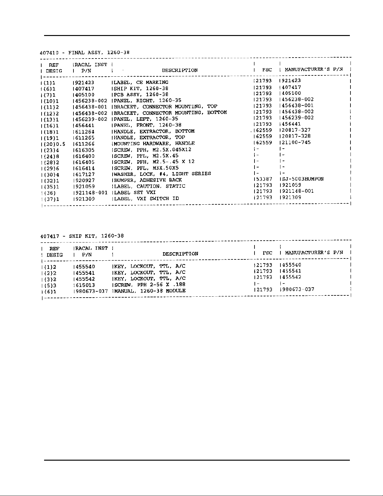
User Manual 1260-38
Parts List 5-3
Artisan Technology Group - Quality Instrumentation ... Guaranteed | (888) 88-SOURCE | www.artisantg.com

User Manual 1260-38
Parts List 5-4
Artisan Technology Group - Quality Instrumentation ... Guaranteed | (888) 88-SOURCE | www.artisantg.com

User Manual 1260-38
Parts List 5-5
Artisan Technology Group - Quality Instrumentation ... Guaranteed | (888) 88-SOURCE | www.artisantg.com

User Manual 1260-38
Parts List 5-6
Artisan Technology Group - Quality Instrumentation ... Guaranteed | (888) 88-SOURCE | www.artisantg.com

User Manual 1260-38
Parts List 5-7
Artisan Technology Group - Quality Instrumentation ... Guaranteed | (888) 88-SOURCE | www.artisantg.com

User Manual 1260-38
Parts List 5-8
Artisan Technology Group - Quality Instrumentation ... Guaranteed | (888) 88-SOURCE | www.artisantg.com

User Manual 1260-38
Parts List 5-9
Artisan Technology Group - Quality Instrumentation ... Guaranteed | (888) 88-SOURCE | www.artisantg.com

This page was left intentionally blank.
User Manual 1260-38
Parts List 5-10
Artisan Technology Group - Quality Instrumentation ... Guaranteed | (888) 88-SOURCE | www.artisantg.com

User Manual 1260-38
Chapter 6
OPTIONAL HARNESS ASSEMBLIES
The following harness assemblies are used to connect Racal Inst ruments Model 1260-38 to
Freedom Series Test Receiver Interf aces.
Each harness documentation consists of an assembly drawing, part s list , system wire list and wire
list
407439 Virginia Panel, Inc. Series VP90 Int erface Harness
407440 TTI, Testron, Inc. Interface Harness
For more information on Racal Inst ruments complete line of Test Receiver Interface solutions,
contact your Sales Representative.
Section Updated 6/97 Optional Harness Assemblies 6-1
Artisan Technology Group - Quality Instrumentation ... Guaranteed | (888) 88-SOURCE | www.artisantg.com

This page was left intentionally blank.
User Manual 1260-38
Optional Harness Assemblies 6-2 Section Updated 6/97
Artisan Technology Group - Quality Instrumentation ... Guaranteed | (888) 88-SOURCE | www.artisantg.com

User Manual 1260-38
Section Updated 6/97 Optional Harness Assemblies 6-3
Artisan Technology Group - Quality Instrumentation ... Guaranteed | (888) 88-SOURCE | www.artisantg.com
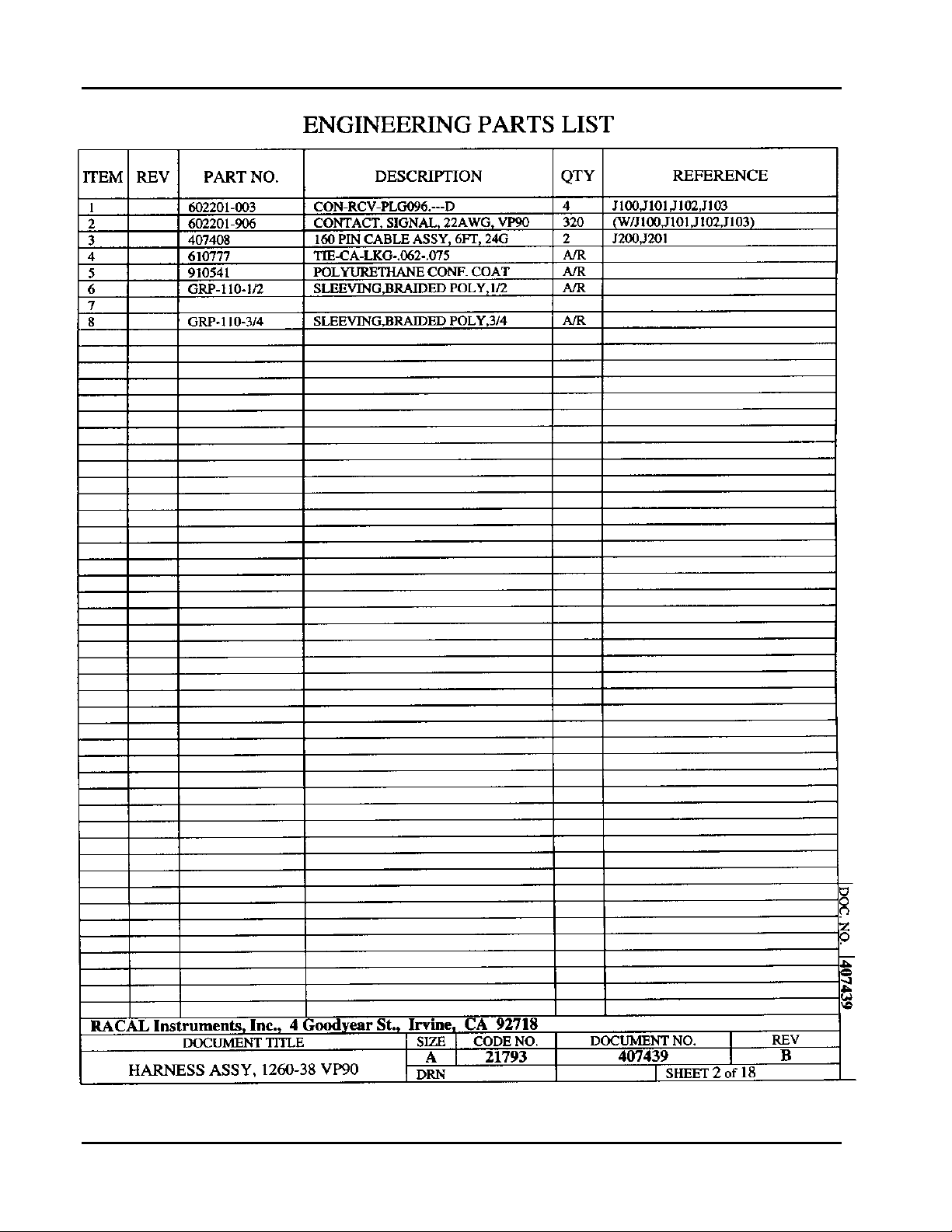
User Manual 1260-38
Optional Harness Assemblies 6-4 Section Updated 6/97
Artisan Technology Group - Quality Instrumentation ... Guaranteed | (888) 88-SOURCE | www.artisantg.com

User Manual 1260-38
Section Updated 6/97 Optional Harness Assemblies 6-5
Artisan Technology Group - Quality Instrumentation ... Guaranteed | (888) 88-SOURCE | www.artisantg.com

User Manual 1260-38
Optional Harness Assemblies 6-6 Section Updated 6/97
Artisan Technology Group - Quality Instrumentation ... Guaranteed | (888) 88-SOURCE | www.artisantg.com

User Manual 1260-38
Section Updated 6/97 Optional Harness Assemblies 6-7
Artisan Technology Group - Quality Instrumentation ... Guaranteed | (888) 88-SOURCE | www.artisantg.com

User Manual 1260-38
Optional Harness Assemblies 6-8 Section Updated 6/97
Artisan Technology Group - Quality Instrumentation ... Guaranteed | (888) 88-SOURCE | www.artisantg.com

User Manual 1260-38
Section Updated 6/97 Optional Harness Assemblies 6-9
Artisan Technology Group - Quality Instrumentation ... Guaranteed | (888) 88-SOURCE | www.artisantg.com

User Manual 1260-38
Optional Harness Assemblies 6-10 Section Updated 6/97
Artisan Technology Group - Quality Instrumentation ... Guaranteed | (888) 88-SOURCE | www.artisantg.com

User Manual 1260-38
Section Updated 6/97 Optional Harness Assemblies 6-11
Artisan Technology Group - Quality Instrumentation ... Guaranteed | (888) 88-SOURCE | www.artisantg.com

User Manual 1260-38
Optional Harness Assemblies 6-12 Section Updated 6/97
Artisan Technology Group - Quality Instrumentation ... Guaranteed | (888) 88-SOURCE | www.artisantg.com

User Manual 1260-38
Section Updated 6/97 Optional Harness Assemblies 6-13
Artisan Technology Group - Quality Instrumentation ... Guaranteed | (888) 88-SOURCE | www.artisantg.com

User Manual 1260-38
Optional Harness Assemblies 6-14 Section Updated 6/97
Artisan Technology Group - Quality Instrumentation ... Guaranteed | (888) 88-SOURCE | www.artisantg.com

User Manual 1260-38
Section Updated 6/97 Optional Harness Assemblies 6-15
Artisan Technology Group - Quality Instrumentation ... Guaranteed | (888) 88-SOURCE | www.artisantg.com

User Manual 1260-38
Optional Harness Assemblies 6-16 Section Updated 6/97
Artisan Technology Group - Quality Instrumentation ... Guaranteed | (888) 88-SOURCE | www.artisantg.com

User Manual 1260-38
Section Updated 6/97 Optional Harness Assemblies 6-17
Artisan Technology Group - Quality Instrumentation ... Guaranteed | (888) 88-SOURCE | www.artisantg.com

User Manual 1260-38
Optional Harness Assemblies 6-18 Section Updated 6/97
Artisan Technology Group - Quality Instrumentation ... Guaranteed | (888) 88-SOURCE | www.artisantg.com

User Manual 1260-38
Section Updated 6/97 Optional Harness Assemblies 6-19
Artisan Technology Group - Quality Instrumentation ... Guaranteed | (888) 88-SOURCE | www.artisantg.com

User Manual 1260-38
Optional Harness Assemblies 6-20 Section Updated 6/97
Artisan Technology Group - Quality Instrumentation ... Guaranteed | (888) 88-SOURCE | www.artisantg.com

User Manual 1260-38
Section Updated 6/97 Optional Harness Assemblies 6-21
Artisan Technology Group - Quality Instrumentation ... Guaranteed | (888) 88-SOURCE | www.artisantg.com
 Loading...