

Page 1
PRELIMINARY
OPERATORS MANUAL
;
MODEL
L1'--'
GPIB
RACAL-OANA
(0) (0)
c=Jc=J
ANALYZER
Page 2

PUBLICATION NO. 980551
PRELIMINARY
OPERATORS
MANUAL
MODEL
.,-..,
CC»
(0)
c:=:Jc:=:J
GPIB
RACAL-DANA
RACAL
18912
Telephone: 7141833-1234.
RACAL
Duke Street.Windsor . Berkshire SL4 1$8, Uni ted Kingdom
Telephone: Windsor
RACAL
18 Avenue Dutartre, 78 150 Le
Telephone:
RACAL
Herrre onstre
·DANA
sse
29.
Telephone: 0
ANALYZER
-DANA INSTRUMENTS INC.
Van
Karman Ave., trvine , CA 927 15
lWX
; 910-595-1136. TLX. 67-8341
·DANA
·DANA
INSTRUMENTS.
0·6078
INSTRUMENTS LTD.
1075351
13J
955-8888.TLX:
Neu lsenburg. Federal RepublicofGermany
610
69811,
INSTRUMENTS S.A.
2·286112. TLX: 412896
TLX
Oesoev
LTD
., DEUTSCHLAND
697215
: 847013
. France
PUBLICATION
Copvrig
Printed in the United S
This bookor
with
ht@198
part
s ther
outwritten
DATE:
1 by Recat-Dana Instruments, Inc.
tates
of America. All rights reserved.
eof
may notbe reproduced in any
permi
ssion at the publishers.
JULY
1981
for
m
Page 3

WARRANTY
Within one yearofpurchase. Racal-Dana will repair or replace
instrument, at
workmanship. All parts and labor charges
Instruments.
in U.S.A., Windsor (07535) 69811 in England, 027-7575 in France,
or 06102·2861/2 in Germany for assistance. We will advise you
proper shipping address for your prepaid shipment. Your instrument
will
be returned 10
PROPRIETARY
This document and the technical data herein disclosed. are proprietary
10 Racal-Dana Instrumen ts. tnc.. and shall not, wit hout express wr
permission of Racal-Dana Instruments, lnc., be used, in whole or in
part to solicit quotations from a competitive source or used for manufacture by a
mation herein has been developed at private
used for operation and maintenance reference purposes
of engineering evaluation and incorporation
cations and o ther do
from Racal-Dana Instruments, Inc.
our
opt
ion,
if in any way it is defect ive in mate rial or
will be paid by Racal-Dana
Just
call Racal-Dana Product Service at
you
freight prepaid.
NOTICE
nyo
ne ot her than Racal-Dana Instruments, Inc.
expe
nse, and may on ly be
into
cum
ent
s which specify procurementofprod ucts
(714)
or
for purposes
technical specifl-
your
833-1234
itt
The
infor -
the
en
•
•
Page 4
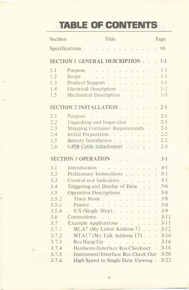
TABLE
OF
CONTENTS
Section
Specificati ons
SECfION I GENE RAL DESCRIPT
1.1 Purpose \-)
Title
ION . I-I
Page
vii
1.2 Scope . \- 1
1.3 Pro
1.4 Electrical Description
1.5 Mechanical Description 1-3
SECTION 2 INST ALLAn ON . 2-1
2.1
~
.2
~.3
2.4
2.5
2.6
SECf
3.1 Introdu ct ion
3.2 Preliminary Ins
3.3 Control and Indicators
3.4 Triggering and Display of Data
3.5 Operation Descript ions
3.5. 2 Trace Mode
3.5.3 Passive . .
3.5.4 S/S (Single Step) .
3.6 Connectio
3.7 Example Applications .
3.7.1 MLA7 (My Listen
3.7.
2 MTAI7 (My Talk Address 17) .
3.7.3 Bus Hang-Up
3.7
-.
.4 Hardware/Int
3.7.5 In
3.7.6 High Speed to Single Data Viewing
duct
Suppor
Purpose . . .
Unp
acking
Shippi ng Container Requirements
Initial Prepara tion
B
att
ery Installation .
GPIB Cab le Attachment
ION 3
OPERATION
and
t .
Inspection
tructi
ons
ns.
Addr
ess 7 )
..
erf
ace BusChe
strument
/Int
erf
ace Bus Check Out
ckout
1-1
1-~
2
-1
2-1
-1
2
2-2
'-
,
2-3
3-1
3-1
3-1
3-1
3-6
3-8
3-8
3-8
3-9
3-11
3-11
3-
1:2
3-14
3-16
3-18
3-20
3
-22
v
Page 5
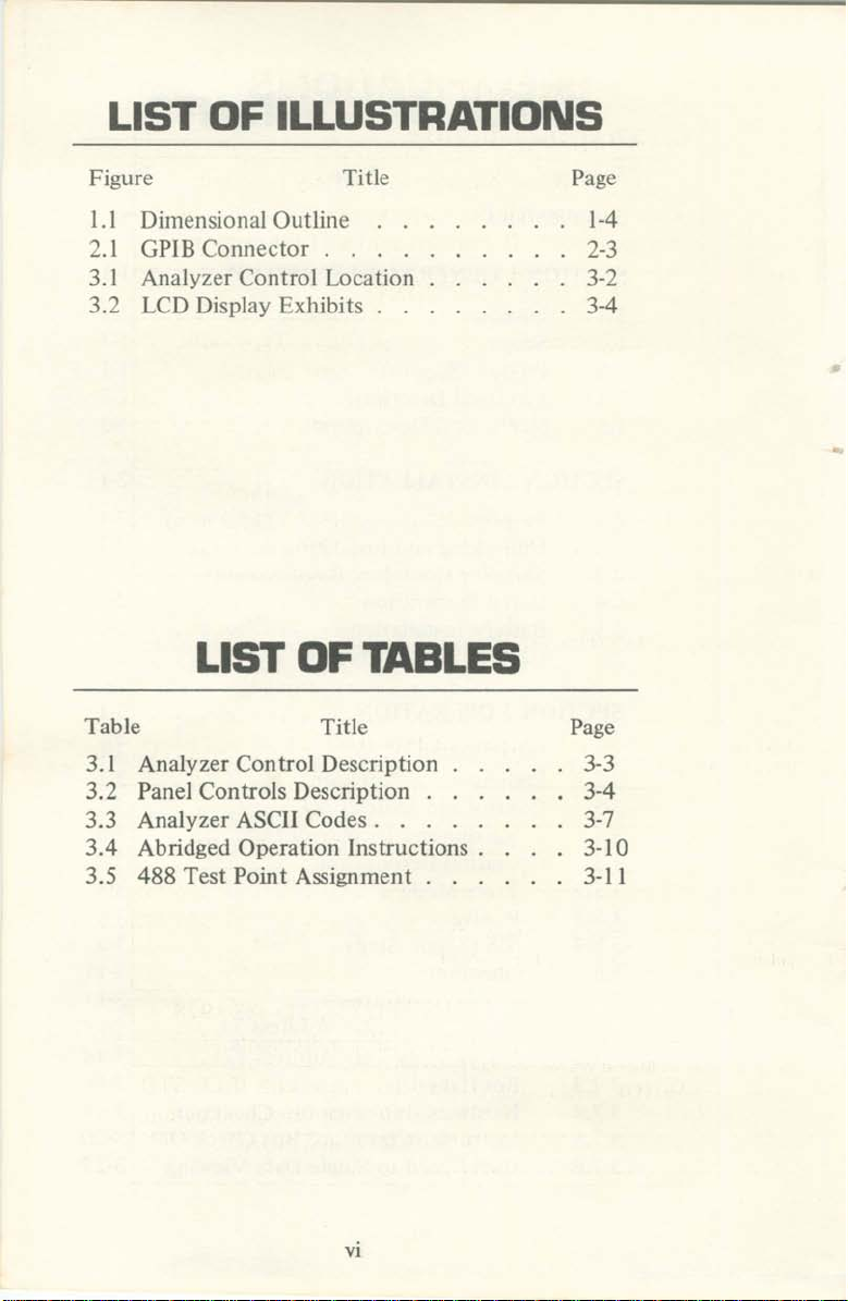
LIST OF ILLUSTRATIONS
Figure
1.1 Dimensional Outli ne
:'!.l GPIB Connector . . .
3.1 Analyzer Control
3
.::!
l e D Display Exhibits . .
Title
location
Page
1-4
2-3
3-2
3-4
LIST OF TABLES
Table
3. 1 Analyzer Control Description 3-3
3.2 Panel Con
3.3 Analyzer ASCII Codes . . . 3-7
3.4 Abridged
3.5 488 Test Point Assignment . . . 3-11
tro
Operat
Title
ls Description . 3-4
ion Instructions . 3-10
Page
VI
Page 6
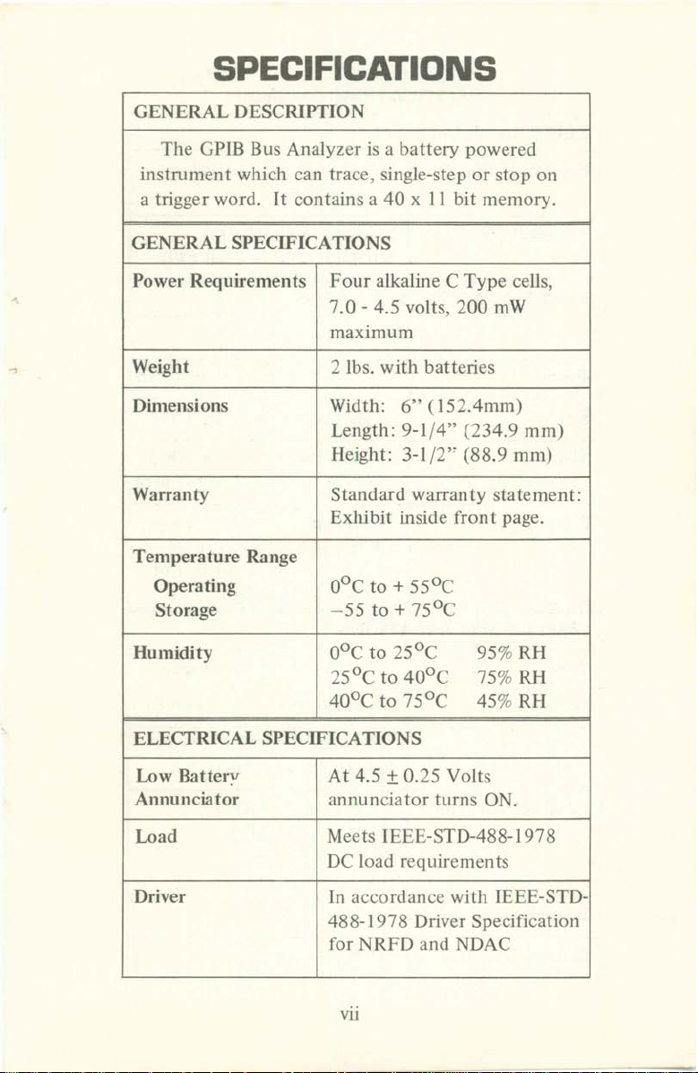
SPECIFICATIONS
GENE RAL DESCRIPT iON
The GPIB Bus Analyzer is a b
instrum ent which can trace, single-step or s
a triggerword.
It
c
ont
ains a40x 1I bit memory.
att
ery powered
GENERAL SPECIFICATIONS
Power Req
uirements
Fou
r alkaline C Type cells,
7.0 - 4.5 volt s, 200 mW
ma
ximum
Weight 2 Ibs. wit h ba
Dim
ensions W
idth
:
tte
ries
6"(I52.4mm)
Length : 9-1/4"(234.9 mm)
Height : 3-1/2" (88.9 mm)
Warran ty Standard w
Exhibit inside fro
emp
eratu re Range
T
O
perat
ing osc to +
Storage - 55 to + 75°C
Humidit
y
oDe to 25
arr
anty state ment:
55°C
°C
25° C to 40°C
40°C
to 7SoC
top
nt
page.
95% RII
75% RH
45% RH
0
11
ELECTRICAL SPECIF ICATIONS
Low Battery
Annu
nciator
Lo,d
Driver In a
At 4.5 1 0.25 Volts
an
nunciatorturn
Meets IEEE-STD-488-1978
DC load requiremen ts
ccor
dance
488-1978
for NRFD and ND
vii
s ON.
wit h IEEE-STD-
Driver Specification
AC
Page 7
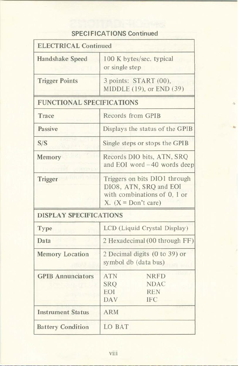
SPEC IFICATIONS Conti
nued
ELECTRICAL
Handshake Speed 100 K bytes/sec. typical
Trigger Poi nts 3 points: START
FUNCT
Trace
Passive Displays the statusofthe
S/S
Memory
Trigger
IlISPLAY SP ECIFI CATIONS
IONAL SPECIF ICAT IONS
Continued
or single s
MIDDLE (19),
Records f
Single ste ps
Reco rds 0 10 bits, ATN. SRQ
and EOl wo rd - 40 words
Triggers on bits
DlOS, ATN,
with comb inationsof0, I
X. (X = Don 't ca re)
tep
or ENIl (39 )
rom
Gr
lB
or
stops the GPIB
Dial
SRQ
(00
).
throu gh
and EOI
GPIB
deep
or
•
Type
Data 2 Hexadecimal
Mem
or
y Location
GPIB Annunci
Instru
ment
Battery
Condition LO BAT
ators
Sta tus
LCD (Liqu id Crystal Display)
2 Decimal digits
symbol db (d
ATN NRF D
SRQ
EOI REN
DAV IFC
ARM
viii
(00
at
a bus)
NDAC
(0
th rou ghFF)
to 39 ) or
Page 8
SECTION 1
GENERAL DESCRIPTION
1.\ PURPOSE
1.1.1 Racal-Dana Instruments prepared this Instruc-
tion
Manual for the Model 488CP
manua
nece ssary to empl
m
proc
ma
pub
users
the in
l provid es th e user
oy
thefeatures
ent.
Also, the manual presents the m
edu
res requi red by tech nical pe
ximumperf
lished specifica tions.
and
str
ument.
orm
ance speci fie d by Racal-Dana in the
technician s read this
with
It
is rec
IB An
the operat ing
designed
manu
into
ople
to
omm
ended
al before operating
aly
zer. The
procedu
the instru-
aint
obtain
that
res
en ance
tilt.'
the
1.2
1.2. 1 The In
tio n for the M
seque nce. starting
through
sections fou r
inclu de : Genera l Desc
Maintenance, Drawi ngs, anti Parts List.
1.3 PRODUCT SUPPORT
1.3.1 Racal-Da na Ins
Engineering Labo
mcn t and Pa rts Department to su p
commitment.
of
Field Represen tatives and Area Service Ce nters with
service personnel available for consultation. The com-
et
pl
Thewar
forwa rd
SCOPE
stru
ctio
n M
anual
pres
ent
odel
488 GPIB Analyzcr in a fun
with the
threeand
thro
e list appears
ranty programdeclarationis presented in
sectio
n o f this
continuing with the Main tenance
ugh seve n. The sec tio ns in the manual
rip
rat
ory,field Engineers, Service Depart-
furt
her su pport is provided by a networ k
on
the last
man
Oper
ato
r's
tion, Installation.Oper
tru
ments maintains a complete
port
two
pages of the manual.
ual.
s th e informa-
ctio
nal
sec
tio
ns on e
ation
the pro du
the
•
.
ct
I-I
Page 9
1.4 ELECT RICAL
1.4. 1 The Model 488 G PIB Analy zer is designed
DES
CRIPTiON
specifically 10 monitor and service abnorma lities in
I
E E E·Standard~48 8-1978
<GP1Bl systems. Th e an
into
any GPIBsyste m (stack
Gene ral Purpose Interface Bus
alyzcr
can be easily
connecto
con
nec ted
r) for t ransparen t
analysis of the bus data.
104
.2 The analyzer features three operating modes:
•
a.
TRACE Mode;
memory.
and
data
is cap tured. stored in
later
displayed fo r analysis.
b. PASSIVE Mode: presents the bus transactions
in real
c. S/5 (Single Step)
actions
These
START
modes
/ENDswitc
provid ing variat ionsofthe
1.4.3
data
inter pret
The user is provided with t
from the L
the bus data:
a. Memory Locat ion displays s
tions in decimals digits
exhibits db (d
time
on the display.
Mode:
to be
stopped
are
enhancedwith
hes which increase flexibility by
allows
or single-step.
ARJ\.I/STE
basic opera tion.
hree
categ
eD
(Ilquid -crystal-display I to visually
tored
00 to 39. The display
ata
bus) when directly viewing
bus tra ns-
o ries o f
data
the bus.
of
b. Data displ ays one
bytes in m
bus.
emor
the 40 hexadecimal
y or can display data from the
I' and
loca-
dat
•
a
c. Bus line sta
status indicators. in addition to low b
and arm are also provided.
tus
indicators plus two analyzer
1-2
att
ery
Page 10
1.4.4 The user can observe signals with short dur a-
tion that are expanded with special pulse stretching
circuits. The REN line is at logic one(O.8Y) when the
tor
REN annuncia
is displayed. The pulse stretcher
turns it OFF for a visible period of time if the REN
lines go to logic zero (2Y) for 2
/-ISor longer. The IFC
line is at logical one (O.8Y), when the IFC annunciator
is displayed. The pulse stretcher turns it ON for a
visible period of time if the IFC line goes to a logic
O IlC
(O
.8Y) for 2 Ji S or longer.
1.4.5 The 488 Analyzer provides a terminal with 17
Test Points (TP) which parallels the GPIB connector.
The 18th TP provides the trigger
output
for peripheral
device. These TP connections expand the diagnostic
applications of the unalyzer. The lest point assignments
are listed in Table 3.5.
J.4.6 The 488 operates from a batte ry pack con-
taining 4 C-typc cells.
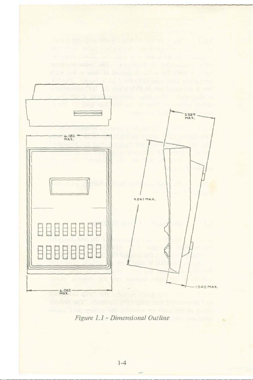
1.5 MECHANICAL IJESCRIPTION
1.5.1 The physical dimensions of the 488 Analyzer
are
out
lined in Figure 1.1. The top view shows the
control panel with the contro l switches for TRI GGER
of
condition, MEMORY and POWER on/
f. The LCD
Memory Location and Data display with nine status
indicators are also located on th e control panel.
1.5.2 The rear panel includes the GPIB connector
and the parallel test poi
(TP) terminals. The bo
tto
nt
panel of the analyzer provides the battery pack access
oor
and concise operatin g instructions.
d
1-3
m
Page 11
Page 12
SECTION 2
INSTALLATION
2.1 PURPOSE.
2.1.1 This section describes the suggested
dures
Dana. Th e sub
preparation, ba
2.2 UNPACKING AND INSPECTION.
2.2. J Prior to unpacking the instrume
the
damage (all irregularities should be n
bill). Care fully remove the in
packaging and inspect the instrurrent forany signs of
dam
apparen t.
2.2.2 If
a qualified person should bench check the unit im-
mediately. If findings are
the carrier must follow immediately.
upon
exterior
age. Notify the carrier immediately if damage is
receiving a new in
jec
ts includ e unpacking, packing, initial
tte
ry supply, and cables.
of
the shipping carton for any signs of
dam
age to the unit is apparent or suspected,
strum
ent from Racal-
ot
ed on the shipping
strum
ent
from the ca
not
satisfactory, a report to
nt,
pro
ce-
examine
rton's
2.3 SHIPPING CONTAINER REQUIREMENTS.
2.3.1 When shipping the in
shipping carton with plastic dust cover
necessary protection. This carton should be preserved,
if
it
is possible.
2.3.2
available,
When the original
r
eco
nstruct the packaging to approach
2-1
strument
shipp
ing carton is
, the original
will provide the
not
the
Page 13

protection designed into the original shipping
listed next:
a. Wrap the unit in a plastic cover.
carton
as
b. Spray the
plastic foam.
c. Place the unit on the plastic foam in the
carton.
bottom
Permit to expand.
about
ccnter.
of
a suitable carton with
d. Surround the unit with plastic foam .
e. Seal the carton.
2A INITIAL PREPARATION.
2.4. 1 Preparing the analyzer for use requires the
GPIB
installed as described next.
connec
2.5 BATTE RY INSTALLATION.
2.5.1 The
screw-locked
2.5.2 To install the ba tteries. turn the b
retaining screw
is freed from the case (the
secured
under
tor
cable and the
battery
battery
the case).
cover on the
coun
terclockwise (CCW) unt il the cover
battery
pack is accessible through the
bottom
other
end
of
power source
panel.
att
ery cover
the cover is
•
::.5.3 Extend the
bottomofthe bat tery cage.
To release the batteries from the cage, pull
the release strap tab that
last cell.
battery
release s
extends
2-2
trap
around
along the
the
Page 14

2.5.4 Install the cells over the batt ery release strap
so that the polarity markings on the cell match the
att
markings on the b
ery holder.
2.5.5 Install the ba
tte
ry cover; start with end that
slips under the case, then secure the screw-lock by
turnin g the screw clockwise.
2.6 GPIn CABLE AITACHMENT.
:!.6.1 The analyzer is attached to a GPIB system
thru a 14-con
ductor
GPIB cable. Care must be taken
when makingthe connection to avoid using two different
of
•
screw th reads. The type
by the color
of
the bolt; black for metric, chrome for
threads used are indicated
non-metric. The analyzer uses the standard specified
metric thread. Racal-Dana part numbers for GPIB
cables are 406845 (I meter), and 4068 44 (2 meter) and
406846
(4 meter). Figure
2.1
illustra tes the 488 GPIB
connector and pin number assignment table.
12 11 10 9 8 7 6 5 4 3 2 1
24 23 22
21 2 0
19
18 17 16 15 14 13
~
Pin No.
I
2
3
4
5
6
7
8 NDAC
9
10
11 ATN
12
Pin
Assignment
DI
D I
DI
D2
010
3
0
104
EO
I
DAV
NRFD
IFe
SRQ
SHIELD
No.
I3
14
15
16
17
18
19
20
21
22
23
24 GND,
Figure 2.J - GPlB Connec tor
2-3
Assignm
0 10 5
010 6
DI
DI
REN
CND
CND
CN
CND
CND, ( ID)
CND
D7
D8
D,(
,(
6)
,(
7)
8)
,(9)
,(II)
lOG
ent
IC
Page 15

SECTION 3
OPERATION
3.1 INTRODUCTION.
3. 1,1 This section contains operating instructions
str
for the analyzer. The informatio n contains illu
of
panel co
a tabular listing
Operating instructions for the analyzer are presented in
two
ways; a description
lowed. where necessary. with a step-by-s
example. Some operating feat ures o r functions are
simple one or two step
arc included.
ntro
ls, ind icators
of
and
connectors along with
the function and purpose for each.
of
each
ope
rating feature fol-
tep
op
erations and thus no examples
ations
operating
3. I.:! The analyzer
1978
describe the operation proceduresofthe ana lyzer and
will review the basics
3.2 PRELIMINARY INSTRUCTIONS.
3.2.1 Before operating the analyzer,itis recom-
mended that the user read th is entire section. then verify
that the batteries are insta lled correctly. Next, slide the
POWER switch to ON. This will activate the display,
indicating that the analyzer is rea
3
3.3. 1 There are basically 4 groupsofcontrols. One
group establishes the mod e of operation, (TRACE,
Passive, 5/5). A second
STEP switch. An
IJITION (IlI O I through IJI0 8. ATN. SRQ. EO!).
bus
environment;
.J
CONTROL AND INDICATORS.
ot
operates
therefore. this
of
her grou p sets theTRIGGER CON-
3-1
in the IEEE-
GPIB in sub-sections 3.8.
dy
group
includ es the ARM/
section
for
STl
opera
>-488-
will
tion.
Page 16

Finally, one group is used to control memory (UPDO
WN
. START-END). The location o f each switch is
shown in Figure 3. 1. Each switch is
3.1
described in Table
RACAL
~""",y
LOCA
I
•
,
;§x
0
P
OWER
ON
·DANA
TION
,
x§x§
§
ATN
SRQ
TRI
6
488
CA"
GGER
GPIS
ANAL
YZER
CONDITIO
0'
0
,
•
x§x§x§
~E~
I f
STA RT UP ARM
TRAa
' 0 '
•
•
N
I
, ,
a
,
x§;
0
ORY
I
§x§
§
0 "
Figure 3./ - Anaiyzer C
x§
§
''"
0000
ontrol
3-1
§
END
§
DOWN
Locatio"
§
sree
Page 17

•
Table 3.1 . Analyzer Control Description
DJ
se:
In
...
T•
.,m.d_
,
x
o
,
rtvn It
•
".
S
lll'
\I t \t
OR'
-1\1"'
........
'
"
00"-'
'IH
\tOR'
'T
•
Slur
""""
RlrTIO~
.....hp...
rh<
3
PN'_
.""In....
.
"ODd._.._.
I
T1lK
11
nu
Id.
lltK
" , _ k O '
'" 3
pc><oh.",
Th< TR\ , E """"" ..
.t>on."
r h< •
11
n"
,.:." 1",,, .
In <; S .-o.J. Ih.
In S S
.. . ",,",-.1
,>,
1" "_,......
110"
A .I
_l>
J<I'
:0
..,."
••
......
1•• .,. ,he
, .... S
~
,~
I R
l<ol:;J11
J'OlI'Kln
.-00.
) J'O"I'K>n.....
po""""
powl_..,
..
In ,
.......
lQItuo.-t
riot
11",
'_'
1 :
MOll
hUt
J :
u.
OI\l
llo
lk .
p<OUt_••,--.
pout"'"~......"'......
'1.1'
_~
p<tw.l
...
n
(;rl
.....
>td
('O~llIII
,au..",
,,1\\1
h
.n<l,'u
'Ik'
(.PI8••11
""
..nl
_..:••""
••
n.... Ill, <I""",)
11\4.._ TkAt L
__
lapul
11
..
\wtI.""
.Iu
1""
_ot
,0
""onIlil1"""'"
_~-..r
pbo""
,11
••
B 11
O'
Ih.
IINJ...
''''''
n.l,
......
r~
....po ,tor lllr (, r iB AR\ 1
SII r ..
an,I)/"
,,,,
..
~c
".n"
" ..
...
.......
",10 ..
d"f'lol
....
~
1"'.
...-
f_
Oulput
,PIOI
'.11'
.......
...
It
-..t.."w
IOf0001 Ihl' ...f
" of
J....»
...
...ldo "t' " ...w4
l<f
1)/"
,II....,n~....
'<>
.U'I...
<1"
",.,.<1
.. . d
1<>
"""
,'10
0(
,
u'tiP"''''t>tI'o
...
'1><'
"""-I
'kGl'II
MIIh<'
p;l"'"
Jon..."
h.ln.I.tuk.
,,-h,nl '01 Iho'
In I
'"
p""·
...
.......
on.
.....'
..
-oIT S.. ,,<h..onl)
nu'
..
~,_
'ttdII
...........
~
l
.....
,0n,II,_..
.~
1"""'P
DIO!I'
".Iw>
_ O,\V
.. , Illctor
...............
,It
....
10'_
mod.
of
<>pr'""'"
III'h........k"..
...onIt..
'.h
or
<lIk>
...
he
lltl
K'>'(~
<I
.1 h
tu.nJoh.
l~n",.:"On
(;(;11t CO
.
n,uJ.
<1.,......
.th
'1'«'<1
~
•. In ru,n Of S S
..
__
III
........"Y
IO R'COni
","",.kd
__
I,.M
"'' SRQ
........
-...
'w'n'Iw
IN
I'ft'UIInl
.uc,
.." to".,••,
bu'
10
p<o.:...,1i
,,"nl.
<lun'.
,t.. ....
..,
li ... III
)
..
_-.0)
'10..'
............. sn r
Jala
T
....~..
plav
,-.,."plt
ono:
'Il
ITIO' ""tuk
d d.." " . Ih
"h.
1Il<llk
TItA
{'E
..-l
l
1><'
lOl-"1
,,,..,
""""'
'tly
paw
11,"1
""ndw
......'.h,
.....
•.
..-
,,,, h
fOf ,
...
..
•
.
••.
...
~
•
to
""'''
Page 18

3.3.2 Indicators includ e MEMORY LOCATION ,
DATA. and
shown in Figure 3.2 and described in Table 3.2.
IQ individual indicat
or
s. The display is
RACAL·DANA
l O BAT
nn
n I
MEMORY
LOCATION
Figure 3.2 - LCD Display Exhibits
Table 3.2 · Panel Controls Description
REFERENCE
488
GPl8
ANALYZER
/_
II
1
_
11
_"_1
DATA
12
DESIGNATOR DESCRIPTION
I
2 SRQ Service Request
3 ATN
LO
BAT
3-4
Low B
att
ery status
indica
tor
status indi ca
Att
ention status
indicato r
tor
Page 19

Table 3.2 - Panel Controls Description Continued
REFERENCE
4 IFC
5
6
7 NRFD
8
9
DESIG
REN
DAV
NDAC
AR~
I
NAT
DESCRIPTION
OR
Interface Clear
status indicator
with pulse stretche r
Remote Enable
Status in
with pulse stretcher
Data Valid status
indicator
Not Ready For
Data status
indicator
Not Data Accepted
status indicato r
Analyzer sta tus
indicator
dic
ato r
10
11
1:01
DATA(OQ-FF
12 MEMORY
LOC
ATI
) Data that is
ON
3-5
End or Id
status in
or
rec
enti
fy
dicator
ded du ring
a bus transaction
in flEX code. Real
time bus d isplay
Shows the relative
location of a recorded bus transaction or if the bus
is displayed directly
Page 20

3.4
3.4.1 Th e user servicing a bus with the analyzer
should refer to the list
sages shown on the label attached underne
(Table 3.3). These bit patterns, normally ASCII encoded,
provide the user with specific trigger words that are
required when setting the T RIGGER CONDITION
switches.
TRI
GGERIN G AND DISPL
of
int
AY
OF DATA.
erf
ace and program mes-
ath
the unit
3.4.2
used to transmit and receive
control systems. The LSD vertical row from 0 to F
(Hex) and the MSD
together list the letters, numbers, special cha racters and
contro l modes applicable to the GPIB (sce
para. 3.4.3).
3.4.3 Table 3.3 allows easy transfer from Hex to
The
ASCII seven bit mode is the convention
data
in GPIB instru
top
horizontal row 0to7 or 8 to F,
examp
ment
le in
binary for setting the TRIGGER CONDITION switches
and also to transfer from the dat a displayed to th e
ASCII character on the GPIB.
Example:
Assume the data display reads 45. The MSD col
4 or C represents the characters @
the LSD column indicates that row 5 lists the charac
ter
E as the one being transmitted on the GPIB. In
ant
reverse, if we w
we would locate "E" on the tab le, then
column heading (E = 4orC, binary XJOO). andthe
LSD row
would give us the setting for the 8
(Le
(E
=5. binary 01
.,
XIOOOIOI ).
ed to trigger on the character E,
01)
to
o. In addition,
note
. Putting them togethe r
D1
0 switches
um
the MSD
n
3-6
Page 21

•
LSD
~
HH
BI~
BI
~
ASC
0 0000
I
2
3
y
S
6
1 0111
8
9
R
b
[
d
E
F
NUL
0001
SO
0010 STX
0011ET
EOT
01
00
0101 E
0110 A
,El
1000
'5
1
001
HT
1010
LF
tot t
VT
11
00 FF FS
1101
CR
1110
SO
1111 SI US
o OR 8
XOOO
II ,"OTE I AS
H
GTl
X D
SOC
NOPPC
CK
G
ET
TCT
Table 3.3 .
I
OR
g
X
OOl
CII
~ O
D
LE
OC
I LlO I MLA I
DC'
C3
OC
.
OCl
PPU
NAK
SYN
ET
'
CAN S
EM
SP
SU,
ESC
GS
RS
2ORA 3ORb 4
TE
I AS
CII
SP
..
#
,
•
•
·
PE
I
D
I
·
•
I MLA 15 I
NOTE 1: BUS INTERFA CE MESSAGES I F ATN ISTRUE.
488
Analyzer AS
XOIO XO
~(JH
I
MLA 0
MLA 2
MLA J
MLA 4
MLA S
MLA 6
MLA 1 7
MLA B
MLA 9 9 MLA 25 I MTA 9 Y
MLA IO
MLA 11
MLA 12
MLA13
MLA 14
ll
ASCII
~
OTE
0 MLA 16 ~ MTA 0
1 MLA 17
,
MLA IB
3 MLA 19 C MTA 3 5
MLA 20 0 MTA 4 T
•
S MLA 21 E MTA 5 U MTA 2 1
MLA22
6
MLA2J
MLA24
e
MLA26 J
•
MLA21
•
c
MLA2B L MTA
MLA 29
·
MLA 30 N
>
UNl
CII
Codes
OR
[ 5
Xl00 XIOl X110 X1 11
I
ASCII
~OTE
I
A
M1A 1
,
MTA
:<'
F MTA 6
G MTA 1
H MTA B X
MTA10
K MTA l1
M
0
I:<'
MTA1 3
MTA1 4 A
MTA 15
OR
d 6 OR E
ASC
II
~ O TE
I ASCII
P
MTA 16
Q
MTA
R
MTAIB
MTA19
MTA20
M
TA22
V
MTA2J
W
MTA2
MTA25
Z MT
[
MTA 21 k
,
MTA2B I I
)
M
TA29
MTAJO n
UNT
I1
A26
·
•
b
c
d
•
I
4
h
;
i
m
0
~
OH I
AS
q
,
,
,
u
,
w
•
,
-
DEl
,
CII
OR
~ O
F
TE
I
Page 22

3.5 OP ERATIO N DESCRIPTIONS .
3.5.1 There are 3 basic modesofoperatio n. T R1
SfS and PASSIVE. These
3.5.2 Trace
Rec
ord
s bus transactions JI high speed
vi
ewing the rec
conjunction
the
aualy
zcr will
::I
.
b.
~Iode
anted
with
ME\
perf
TRACE
the T RIGGER
pane l switches. When the search is comple ted
and data reco rded, AKM is
TRA(,E -U1~/l)OWN;
me
the reco rded values
MEM
location
sequence can be
quir
-ARM: The analyzer will search
mory
is displayed in HEX digi ts along wit h
ORY
of
ed.
art
described below:
:
and
tran sactions. When
IORY.ARM
orm
as follows:
CO~
LOCATI
and STEP functions.
D1T
IO!"
A da ta by te cap
of
ATN.
ON sh
operat
that is set on the
turnedOFF
tur
SRQ
and EOI.
ows
the
the recorded data. TIle data
stepped
up o rdown as re-
relative
\CE.
all
ows
ed in
ed in
,
\
for
.
c.
TRACE-STEP; When 51 EP is activated
during the search period, the search stops and
the balance
with zeros. (Note; the bus hand shake is
sto pped while
3.5.3 PASSIVE:
Middle po
:I.
Display exhibits the bus on a sampled basis
(ap
prox
ima tely :20ttmcs/scc.j. MEM
L
OCATION
isbeing displayed rathe r than memory.
of
mem
STEPis held d
sition
s
how
on
3-B
ory
locati
ons
are filled
own)
.
the
TRA
CE-S/S Switch.
OR
Y
s db to indicate the data bus
Page 23

3.5.4 S/S (Single Step ):
0
11
The display shows the bus
MEM
ORY LOCATION shows the data bus (db) being
a sampled basis.
displayed. When operated in conjunctio n with ARM
and STEI) functions. the an
aly
zer will perform as
follows:
a. S/5-A RM: The
ana
lyzer handshakes bus
transaction at high speed unti l the TR IGGER
WORD is recognized. While the searc h is in
progress the ARM indicator is displayed.
ARMing allows the user 10 "fast forwa
rd"
when in single step.
b. S/S·STEP: The bus is allowed to advance one
hand shake each time STEP is act ivated and
released. If a search is in
abort
it.
I. ANRS: The Acc
ept
or NotReady State
pro
gress, STEP will
isactivated when STEP switch is engaged.
2. ACDS: The Accept Data State is entere d
when the ARM
·ST
EP switch is in the
center position.
ent
3.5.5 Abridged operation instructions pres
Table 3.4 are placed on the bo
easy r
ef
erence. This table shows the main operating
tt
om of the analyzer for
ed in
modes, which can be used as a guide after becoming
familiar with material in this manua l.
3-9
Page 24

r
Table 3.4 • Abridged Operation Instructions
MODE
T,ee.
ISlorage 01
in memorvl
p
o
..
Sinvle
eventt
,
ln
Step
Stop on Trigger
TRACE-S/S SWITCH SETTING OPERATING INSTRUCTIONS
St'
llr;gger
Set switch to TRACE
Set switch 10 mid position 1.
1.
Select
2.
U5eARMposition to arm analyzer.
3.
Wail for trace 10
••
Reulll1
5.
All
Ob$«v
2.
SIt IWitch to SfS 1. Use STEP
Sellwit
chtoSIS
1. Set
Use ARM position to¥mitI,IYllIf.
2.
3. Wait ' Of tr;qget' lARM indicatOf offl.
u se STEP po$,tion 10 advance bu stu,"ic
••
condition.
memory
othe
l bus Ir
' figgef condItion .
()n~d
r swile
position
trigger
com
data
hn
.fficon
position
plete (ARM indiClltOf
using UP-DOWN switch.
ere 'nactive.
displa y.
10 lIdvance bu s
1ST
ART
tr.
ltic..
-mid ·ENDI ,
off)
.
.
Page 25

3.6 CONNEcnONS.
3.6. 1 Indication of thevarious test points contained
on the rear connector is shown in Table 3.5. The pin
designation o f this standard GPIB connector is shown
in Figure 2. 1.
Table 3.5 . Test Point Assignment
A
SS
TEST
POINTS
IGNMENT GPIB-
NUMBERS
PI
N
TPI
Common 12
.18·24
TP2 Dl0 5 13
TP3 DI0 6 14
TP4 DI
07
IS
TI'5 Dl0 8 16
TP6
TP7
TP8 Dl
TI'9
TPIO EOI
TPI I DAV
DlO
I I
Dl0
2 2
03
Dl0 4 4
3
5
6
TPI2 NRFD 7
TPI 3 NDAC
TPI4
SRQ 10
TPI 5 ATN
TP
I6
IFC 9
TPI 7 REN
I8
TP
\
TRTG
8
11
17
N/A
3.7 APPLICATION EXAMPLES.
NOTE
The instructions provided assume that power
switch
is
is ON and that the anatyz
normal.
er
operation
3-11
Page 26

3.7.1 MLA7 (My Listen
Addr
ess 7) Trace Mode
EXAMPLE
This is an
was
senttolisten address 7.
I.
3.
I:
example
The
mode
TRACE
data
With trigger position set to
ger condition
The
follows.
The
tocorre
MLA7 for My Listen Address 7). Look for
MLA7 in Table 3.3 .
switches sh
appears in a column
I indicates ATN should be set
means the ATN trigger
should
CONDITION switches
don't
purpose
triggering on the GPIB Iden tify
occurs
one.
is used to re
.
rest o f
TR
IGGER CONDITION switches arc set
be set to I.
care
whcn bo th ATN
The switches
of
of
memory
spond
ould
(X)
of
setting
howtorecord
operation
cord
a ppears at
is filled with
to listen
The
be set
and EOI is
to
that
The
and
EOI
shouldappearasshown.
is set
and
the
addres
table
and view
to
view rec
START
start
of m
s 7 <called
showsthe
what
TRACE
orded
. the trig-
emo
ry.
data
that
1)10
XOIOOIII. MLA7
says
NOTEI.Note
true.Thi
condition
remainingTRIGGER
SRQ
set
to zero.
to
zero is
and
EOI are set to
switch
are set
The
to
avoid
state.Thi
.
s
to
s
4. TIle analyzcr is ARMed by activating and
releasing the ARM swi tch. The ARM lndica
tor
will co me on while the analyzer is
searchi ng for theTRI
rec
ordi
ng the da ta. This may be a very b rief
ti
rneif
there is mu ch activity on MLA7. After
the
data
is recorded,
as
shown
.
3-12
GGER
CONDITION and
the
display will appear
Page 27

Trace : Example I
RACAL·DANA 4
,-,,-,1
uuL
.....
0 ."
..
OC.,,"'"
TRIGGER
I
,
•
t§
0
P
OWER
ON
x
A T '" S
• • •
§x
~x
RO
88
GPle
ANAL.
I
I
0."
CO"'O
0'
0
§x
§x
TRACE
'
0'
YZE
~
ITI
O'"
~x
M EMOR Y
(
I
START
R
QID
a
~
(
....
0 I
~
,
x
~
UP
I
,
§~
, 0
I
'R"
3-13
§
.is
§
END
§
oa.v".
§
stee
§
~
x§
,
0 "
x§
Page 28

3.7.2
EXAMPLE 2:
MTAI7
( My Talk Address 17) Trace Mode.
This is an example of how to record and view what
is sent from TALKER address 17, and to view the
sequence which the controller used to add ress the
T
ALK
ER.
3.7.2.1 With switches set up as show n, the trigger
condition corresponds 10 MTA 17.
3.7.2.2 Momentarily engage the ARM switch. AR
t\.
indicator comes ON.
3.7.2.3 Data is recorded in the first half of memory
until the trigger condi tio n is met. Th e trigger word is
ct
stored at location 19 and the next 20 transa
of
recorded in the last half
memory. After th is is
ions are
accomplished the ARM goes OF F. The d isplay shows
MEMORY LOCATION 19 and DATA 5 1. Thi s
dat
corresponds to MTA 17.
3.7.2.4 Transaction s before the trigger condition are
recorded in memory locations 00 to 18. Transactions
after the trigger condi tio n are recorded in locations 20
to 39. These are viewed by the use of the UP/DOWN
switch.
1
a
3-14
Page 29

Trace: Example 2
RACAL
-DANA
In'-
1-1_'
MEMOR Y
LOCATION
I
,
a
~§
o
488 GPlSANA
DATA
s
LYZE
A
•
S/
S ENDClONN STEP
3-15
Page 30

3.7.3 Bus Hang-up, Trace Mode.
EXAMPLE 3:
3.7.3.1 Set-up trigger condition to a value that will
not
occu r during yo ur operationofthe bus. For example,
if no parallel poll exists in the system (EOI and ATN
asserted), set the switches as shown. Note that the
START/END switch is set to END. Thi s is done so
that the largest number
in memory
(39).
of
transactions will be saved
3.7.3.2 Mom entarily engage the ARMswitch. ARM
indicator comes ON.
3.7.3.3 Allow the syste m to hang lip.
Stop
3.7.3.4
recording by engaging STEP switch and
releasing it. The display shou ld show MEMORY
LOCATION 39 and DATA 00. Memory locations 00
to 38 hold the
39
steps that lead up to the bus hang up.
3.7.3.5 View the recorded transactions with the UP/
DOWN switches. The last recorded transaction will be
in location 38. The one before that will be in location
37, etc.
3-16
Page 31

Trace: Example 3
RACAl
-I
MEMOAY
LOCATION
I
•
x
m
c ,
POWE
A
ON AT N
-DANA 4 88
ti
t:
rir:
-lU
TRIGGER
-r s
§x
§x
,
t
'Ra
DATA
§x
aor
GPIS
ANALYZER
Ll
CONDIT
000
,
•
§x§x§
, , ,
,
I
TRACE
c:ill:J
ION
3
M E M OR V
(
START
~
I
~D
.~
I
I
, ,
§~
x
, 0
I
UP ARM
x§
§
•
§
0 "
, , ,
x§
3-17
§
5>.
§
END
§ §
lX:MiN
sr
ee
Page 32

3.7.4 Hardware
EXAMP LE 4:
This
examp
checking
out
/Int
erface Bus Checko ut , Pas.sIve
le shows how to view bus lines while
the hardware for a new interface.
3.7.4.1 Place the analyze r in Passive mode by moving
the
TR
ACE-S/S switch to the middle position.
I\OTE
None
of
the
other
switches have any effect in
PASSIVE mode.
3.7.4.1 When the hardware checking
face is told
to
assert DA V. the lJA V indicator on the
out
the inter-
display should come ON. All GPIS lines can be directly
viewed when in the Passive mod e.
3-18
Page 33

Passive Example 4
RACAL·OANA
,
I_I
-I
_/U
MEMORY
LClCATION
I
,
•
x
x§
ON
ER
§
ATN
SRQ
m
0
POW
488GP'S
till
1/
__
DATA
TRI
GGER
e e
x§ x§
'0'
ANALYZER
I
CONDITI
0'
0
,
I r
TRACE
ON
a
x§
MEMORY
STAR
x§
T UP
UEl
,
x
ARM
I
,
§;
I
,
0
§
0 "
§x§x§
3-19
§
",
§ §
END
OOtt'VN
§
""
Page 34

3.7.5 Instrum
EXA
MPLE 5:
ent
Character Review, 5/5.
This example sho ws how to view an ins
trum
ent'
react ion to different characters on a step by step basis.
3.7.5.1 Some instruments react directly to commands,
others might requ ire a terminator such as carriage
re--
turn or line feed.
3.7.5.2 To sec this cond itio n displayed , set the
analyzc r in S/S. Program the
co
ntroller to send com-
mands to the instrument. Single step the bus using the
STEP switch on the aualyzer.
3.7.5.3 The instrument's reaction to the different
characters can be observed on a step by step basis.
s
3·20
Page 35

Page 36

3.7.6 High Speed to Single Data Viewing. 5/5.
EXAMPl.E 6:
This example shows how to move past a large
inf
orm
ation quickly and then view a particular group
of
dat
a by single ste pping.
3.7.6.1 Place the ana lyzer in
CONDITION to the
data
5/5. Set the TR IGGER
where the single stepping is to
body
of
continue. This might be LISTEN addrcss MLA4 as
shown.
3.7.6.2 Momentarily engage the ARM switch. The
ARM indicator will come on while analyzer is searching
for the trigger condition. When the ARM
indicator
goes
off. the ana lyzer will have found the trigger word and
be read y to single ste p from that point forward.
3-22
Page 37

5/5: Example 6
RACAL-
UClL
MEMORY DATA
LOCATION
I
,
,
;§
x
0
POWER
ON
DANA
/1
T RIG
-r
s
§
x~
,R
"N
488
GP IB
_ILl
GER
0<0
,
0
x
§x§
O
'
01
ANALYZER
~
I
CO NOI
TlO
•
0
I r
TRACE
N
a
x x
§
,
MEMORY
START UP
[EO
~
1
-':
, ,
0
x
§
1
I
o ,
§~
I
ARM
§
OH
~
x§
x§
§ §
'"
3-23
§
EN D OCM'N
§
"'''
Page 38

U,S,REPRESENTATIVES
RACAL
ALABA
o.lA
500"-,
A_..,...
P. O .
80_
Mob".,Al.
(BOO)321
ARIZONA
I'L.S A.
..
<>e••,
•
001
No""
su..
~
61
Ph"."'.,AZ
16
021219
A
RKANSAS
SAl.!..t.~'!
No
nh.m
R.-:.'
D.-ne'''S'''.
"'''1'''
''
1'
1
400
Co.
s..... Cl
.....CA
lofOllI121
SOUlh.."
""'.
' D
....
18\11 2 \/'
0'"
.0.Bo
o C 19!>4 1
1'
I
.......
. CA,
In
. ,
833
,
21316288825
COLO
R A
PLS
A_'.'n
l1S5E.a"
0-.
.....CO
1
3031113
CONNES
S..M_h..MII.
DELAWAHI
R_c. -Ce .. . InsH ,,,,,
16
091
853-1605
A
ll"
Sl'.
I
R~;on.
-DANA
231
1
3660
-8998
...
,""
310
, A
8!>0 11
1!o3 1
· S..O
~~
...
••
10
O".
~.
-.n
. " Av• . S .. " .
9S~
2~2
I
n~",,,,,_
Il . , m . ""'_
92113
:1180
DO
Inc
.ncw A... . T ·9
1:I01Jl
121
8
T'CU!.::
V" 91018
'
0 ' 1,
...
)
1
•
....
"onls
a
.
.nlS
lo.••hom.
If'>(;.
'dO.
O
"
Inc.
Inc.
DISTRIC
f'L~~
SootMI A_ ••,
2O!o1 N .W .
Pu rn
'3G51913-BBo.t
(8
18
G-2)
S-A......,
Instruments
T O FCOLU
s..
Vi.,ln
l.
..
.
~
l11h
.......
00'3218
001
432·5618(FLonl
P.O .
80
.
Rock1.dU-.
P.O .
80.
Lo"
"....
ood
1'.0.8
0_
8 ' .
...."'0".fL
e.o. 1:10.
,.
r.
6
F!'v
P. O. Bo_
lo I8l
....
le . FL
GEo~C'~
P.O.
80_
Ae-o"".CA
~
Not,,,
:
se.
So,,,'"
s..
ILLINOIS
Com
,"
3!i3!i
W .
C""'
.\lIO.
(312
1 5
394838
!..
N~
Com
,. I
59
W .
12
I" tl ,. "
.,p
13171
2!l3
'--
~
h.
F L
o r
998
!l17
f L 32
1
00
, f L 3
21
1163
33!i
911
3
....".F L
3132
3290
..
'K
2 1
48
3 0 1 0 1
Of
.....
Colo.
_
P.,.,..,..
IL
6
0659
86
." S"..,
o ll• •IN462
1&81
955
A ...."u.
3306.
50
06
33
2
60
MBI
4 1 1
Oft
yl
A
,c.
lne.
IO
WA
C
.....
...
204
COIf,,,~
C
._
R.",.,.
13HtJ 3 11
KANSA
S
Coon
•• '
N.lI
!:o920
sr.
.....
,,_
(9
131122
KE~~_K_Y
E..,.." :
W.
'l.'
":S_ I"d
L OUISIANA
MAINE
-S-M....
'!1!'~
MASSA
C H UStTTS
R
....I·[)en.
(611189~
A
I.o
$M
(Revlon.O
M I
CHIGAN
c.
••••. MeCo . m .e
2:)9g5
F<_
"..m'"9
13 131
"""'
,on.
4111100
MINN ESOTA
.•
5
100
ECI.".
M , " " •
.,o....
(6
12,
835306
M IS S IS S
MI~S~
t!..
~I~
Com'e
l
10210P
.\I
S, .
LOw • • M O 6
43
14'428
M ONTA N A ·
Ro . N t
.10.....
4
oon. K S
_
o
n,o
!l2402
662
(E" " I• .....,OOl
943
. S u .'. 10 2
M ,
..
1030
s..
l.".
- S••T
....
chu..
I'::'.Q
-
$M
VI,,,i,,l.
l" n.u.....
7195
V
"g,ni.
ffic
IPP
_!
..
. 8 Ivt!Su" . 1 13
b Mlll
...
M I
Indu.
MN
I ·
Se.
. 1
P
4lW2
0
s..
3132
nllInc.
Ao
P. " c .
.,1o.0._
4
,,,.1
!:o5
43!:o
A I.b....
O
.ellO"
02
" .
BIYCl.
.
Page 39

NE
W
':!..~~~!:!!!!~
5.-
M_
~~!'!...J~
So""'.n
No.
'''_n
~.I
·o.ne
423-3
\20 11
Alw
s..
(R~io
~EWME~~
P LS An oc'.'.I. I
4300
A
l!t051
""EW
--
Soul
No'
NYC
R..,.l
1516)
AIIO
Vi ' lIinle
n .
1
H S,I"•• A
lbuq"
.'que, NM
255 233
YO R I(
----
h• •n :
I""'
" : P,O .800
& Lon
.o.n.lnlt
:142·~
s..
ViI"n'e
........" .
S_0.1_
In"r..menu Inc.
039
O
Wu)
5.-
lll
5.4
....
nc
.
".n
...
, S . t:.
87108
0
N
....
Joo... y NO
ol. nd COI...... b•• . S C
........ntolnc.
IR.on"O'lIce)
~~RO~
See
Sou.h
c...oh
...
~O""~
See
OHIO
c:.
...
,.McCo ,
15
Rock
,idge
Enlll_ODd
836-0951
(5 13 )
:1:1650 L
o,.,n
f."",....
0
0 l<LA010 M A
oa
69215,
T"
(8 1 8)
P.,~
16
11195100
••
M.
'~
...n"A..
Can.onA"e.
lu ,OK74 186
49
6 ·
1457
, 0 01 4 5322
M.n_w'e
,,,
1C&P."c
RGed
Rd
,
O h.o
.
441
oC'"h"
llh
.
:16
ORE
G O""
~.I
·o.
150312
PEN
i;I;.;~~
W ' n
c.
409
Mon,o.
(4
PUERT
~H0.p~_!!i
Sot.<
SOUTH
TENNtSSt E
TEXA
0.,.
3330
_ "0..,
11131
'
0.1••. 1 X 15 :134
1:1
833110
SanAn,o",o.'X
1
300
A"",,,,.
l5 12 14 51
...In..
41·8624
NSYLV""N
kC
e.
y R
" ,II. , P A15146
12137:14415
O R ICO
S..A
.!-.~_N_
S..Mn...,n"
AI"",,"''''
21563
DAI<OfA
s..
M,nn. IO'.
S
M.,
....
a ••"'110,.
f)(7105
78 0
:1!>
'':135P. o ' "
14)bbl
51213
...
1'1".
4:1303
H"M '. " "
rx
eacc
51'4
-o.l
<><n
O.d
I.ham
"., Auoc'.
1 1
''
"c.d
'1
1
[I
I
H/~.2
urAIl
I'L S A
..
u~"""
5 ..
,,'h
.~
.. (;
"Y.U••h8411
•. In c.
S'~'''
. ~_M. lM<:h "
520
:1
L
5,,11
lI46hIl7:1\,1
IIlO
VE
R
MONT
""..,.nu
' A
.......
..c
110P...
~ .
2922
7
18:11"
, .,
S'.
.
S.. " . 15:1
U.S.REPRESENTATIVES
V I
"(.;I
N I A
P. O .
604
n
. 1
iW.Gre.n
8
4)5
M I
ADA
•••In..
A.,,,_O
.....
....
ed
. L.. w :1S1
lAdy
Le
L.u,.nl
...
Ca",
c.rn~
King
13:16
·5983
VI"
GINIA
Se.
e,lIn
,
....-6042
NG
\I'O
.On
0600
Ell
'_lo
KIZ5-6g
12$-
11131
""","",
P. O .
H4 M2 M ..
_5829
plallC.nu.
...
.
~""
T
aN
.....
V"Vin
W'
lC.
S..CO!O'e<Jo
, , ,,. ,,..Lld
...
0"".
3K
y . S.. " .
C.V6H
.
oel to
1
'n
2 J 3
Inc.
c.
!>
oelt
Sp"n!Jf'e1d.VA
(7031941
.....ASHINGTO""
WEST
~
.......
W.II••n Se . P • . (W
W ISC ON S IN
Co""
2141!
N_
(4 1
WYO
CAN
W."
1:100
M
C_
C4 16 1 6 2!>
880
011_4.On
c:.....,.
U!;131
750
SI .
Can
(5 1" 1 1
:tiI:l08
200
S'-Alb."
Caned.
40314584669
(
4211
1l.rn.bY,6
160414342611
l
2:1Ui1
·
s..
ll.ld
53151
0",..
'•• oo
P$K.
8h.d.
1.
1
o.-_n
••
....'n)
A"
.. ,
U.,..
Su
Su".
509
3Y6
. ·'11
•••
21<
J
3 1!>
Page 40

~
i
l-
!
!
!
1
I
i
u
,
.;
<
o
z
~
•
u
~
s
<C<
z
•
•
•
•u•
z
.
~---
s
•
,
i
1
'6
I
11
I
i
,
,
,
--.-L.
~
..l--
o e
_--'
e
-----,-
•
•
u
z
ffi
~
-~
-~
;
Page 41

REPAIR REQUEST FORM
To allo w us 10
following outline and include a co py with you r inst rumen t to be sent to
local Racal-Dana re pair facility.
Model Number _
Serial Numbe r _
Company Name _
Address _
Cily _
Cont act _
I. Describe, in de
2.Ifyou are usin,your unit on the bus, please list the program strings used and the con troller
type , If possible.
bette
r underSland yo ur repair reques ts, we suggest you use the
tait.tb
e problem and sym
your
Options _
Oate _
P. o .#
State _
Phone Number _
ptoms
you are having.
l ip Code _
J. List all inpu t level. , and freque ncies this failure occ urs.
4. Indicate any repair wo rk previously performed .
S. Please give any additional inf
faster repair lime. (I . E., mod ifications, et c.)
or
mation you feel would be beneficial in facilitating a
 Loading...