

Page 1
WPLED52 Series INSTALLATION INSTRUCTIONS
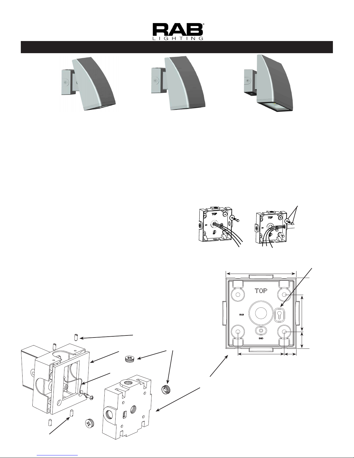
WPLED52
Standard (15 Deg)
Thank you for buying RAB lighting xtures. Our goal is to design the best quality products to get the job done right. We’d like to hear your comments.
Call the Marketing Department at 888-RAB-1000, or email: marketin g@rabweb. com
WPLEDC52
Cutoff (7.5 Deg)
WPLEDFC52
Full Cutoff (0 Deg)
IMPORTANT
READ CAREFULLY BEFORE INSTALLING FIXTURE. RETAIN THESE INSTRUCTIONS FOR FUTURE REFERENCE.
RAB xtures must be wired in accordance with the National Electrical Code and all applicable local codes. Proper
grounding is required for safety. THIS PRODUCT MUST BE INSTALLED IN ACCORDANCE WITH THE APPLICABLE
INSTALLATION CODE BY A PERSON FAMILIAR WITH THE CONSTRUCTION AND OPERATION OF THE PRODUCT
AND THE HAZARDS INVOLVED.
WARNING: Make certain power is OFF before installing or maintaining xture. No user serviceable
parts inside.
MOUNTING TO A WALL
1. Orient box so that “TOP” is on top.
2. Secure Wall Mounting Box to a sturdy wall. Use
appropriate mounting hardware such as lag bolts
and anchors with washers suitable for the mounting
surface.
3. Feed supply wires through Wall Mounting Box.
Check that Gasket is fully sealed.
4. Bring xture up to the Wall Mounting Box and slide
the stainless steel Tether from the xture into the Key
Hole Slot for hands free wiring.
5. Wire the xture using suitable wire connectors.
6. Place wired xture over the Wall Mounting Box and
tighten the Top Screws. Now tighten the Lower
Screws.
7. Tighten Close Up Plugs and apply weatherproof silicone sealant to all unused conduit entry points. Also
use sealant between the wall and Wall Mount Box.
Top Screws
Gasket
Wall Feed
Conduit Feed
4.57”
Close Up
Plugs (4)
3.0”
Hardware
(not supplied)
Key Hole
Slot
2.4”
1.09”
.79”
Tether
Lower
Screws
Wall Mount
Box
Note: These instructions do not cover all details or variations
in equipment nor do they provide for every possible situation
during installation, operation or maintenance.
Page 2
WPLED52 Series INSTALLATION INSTRUCTIONS
WIRING
Universal voltage driver permits operation at 120V to
277VAC, 50 or 60 Hz except xtures factory ordered
with a 120V photocell (/PC)
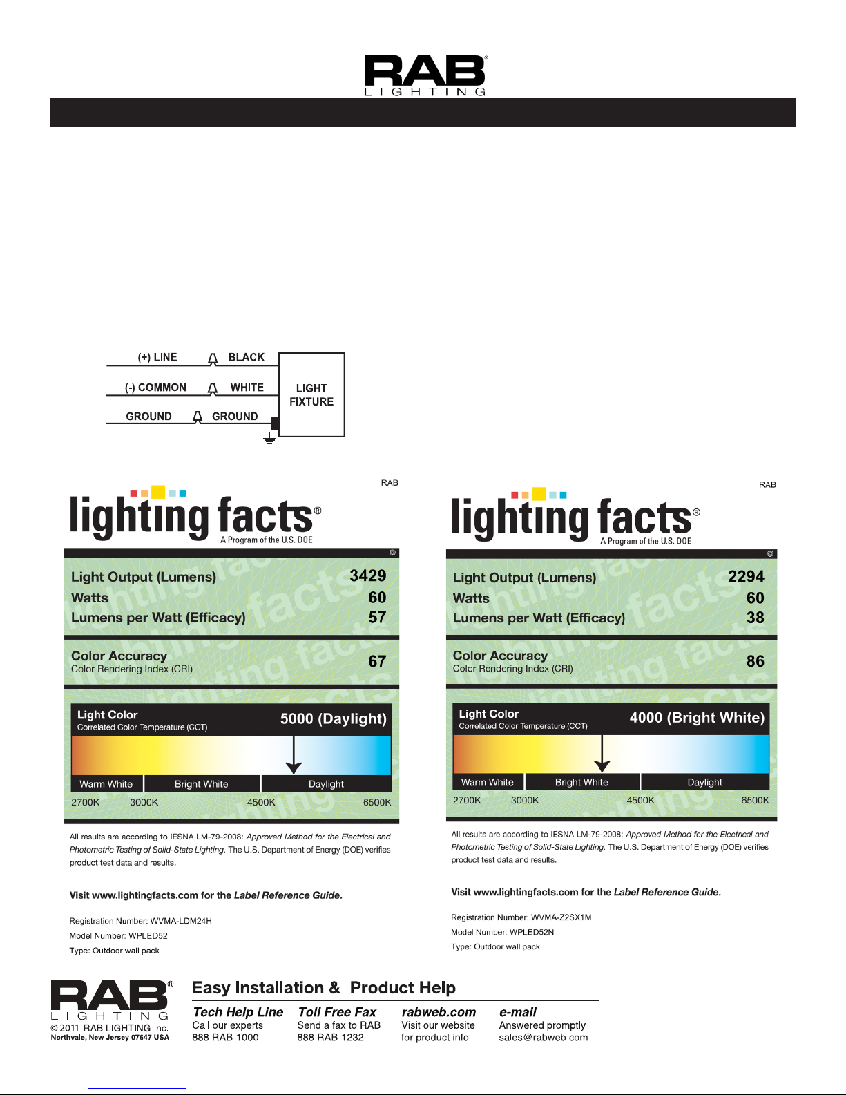
1. Connect the BLACK xture lead to the
(+) LINE supply lead.
2. Connect the WHITE xture lead to the
(-) COMMON supply lead.
3. Connect the bare copper Ground wire from xture
to supply ground.
WPLED52 Cool WPLED52N Neutral
CLEANING & MAINTENANCE
CAUTION: Be sure xture temperature is cool
enough to touch. Do not clean or maintain while
xture is energized.
1. Clean glass lens with non-abrasive glass cleaning
solution.
2. Do not open the xture to clean the LED. Do not
touch the LED.
TROUBLESHOOTING
1. Check that the line voltage at the xture is correct.
Refer to wiring directions.
2. Is the xture is grounded properly?
3. Is the photocell, if used, functioning properly?
WPLED52-IN-0711
 Loading...