

Page 1
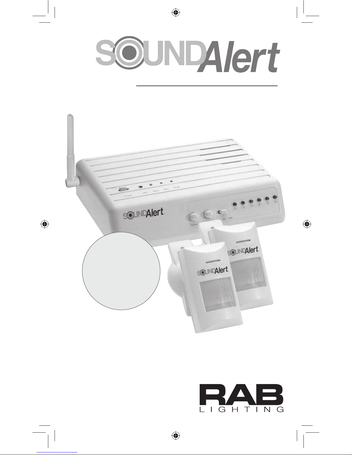
Talking Wireless Detection System
Installation Manual
Tells you
where & when
someone’s
been detected
™
SA Manuel.indd 1 4/29/05 3:06:43 PM
Page 2

How SoundAlert Works
SoundAlert is the Talking Wireless
Detection System that tells you
where and when someone’s been
detected.
The Sensor/Transmitters can be
located indoors or outdoors and
when movement is detected, they
send a signal to the Base Station.
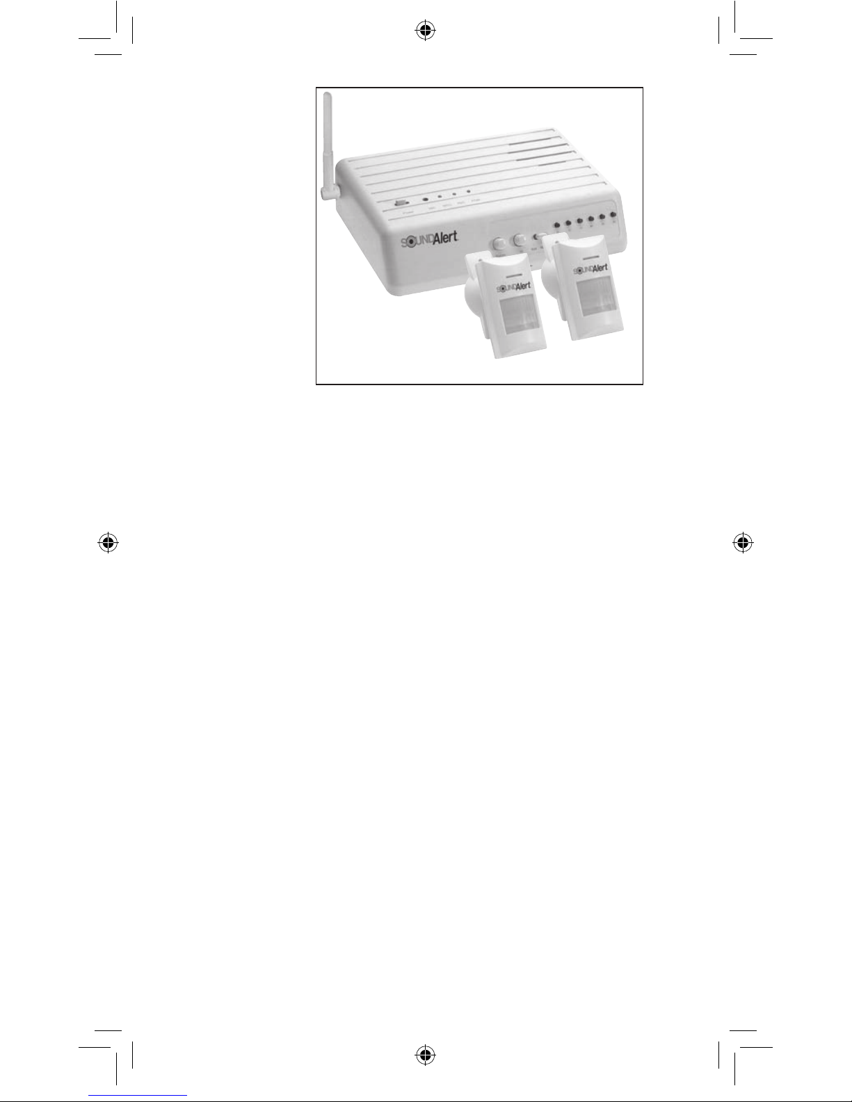
The SA12 system consists of a Base
Station, plus 2 Sensor/ Transmitters
and the SA24 System has 2 Base
Stations and 4 Sensor /Transmitters.
Additional Base Stations and
Sensor/ Transmitters can be
purchased separately.
The Sensor/Transmitters are
battery operated and they transmit
radio signals to the Base station.
The Base Station has six prerecorded messages, or you can
easily record your own messages.
The Base Station also has 4 “C”
relay dry contact outputs to activate
other devices, such as X10,
Leviton, or Lutron controls.
Specifications
Base Station
• 6 separate voice messages of 6
seconds each. Use pre-recorded
voice messages or record your own.
See page 6.
• Receives signals from an unlimited
number of Sensor/Transmitters
• Speaker Volume Control
• Voice Message Test Buttons:
One button per zone
• 4 “C” relays trigger X-10 or Leviton
DHC devices
• Missed Message Indicator:
Flashing LED
• Missed Message Playback:
Push Button
• FCC Approved
• Low Battery LED indicates that a
Sensor/Transmitter has a low battery
• Low Battery voice message identifies
specific zone with low battery
•
AC/DC Power Adapter -
6’ cord length
• Power Requirement: 120V AC 60Hz
•
Power Transformer 9VDC 1 AMP
• Installation: Wall or tabletop
Sensor / Transmitter
• Detection range: 40’ x 40’
Adjustable sensor patterns (see
page 9)
• Adjustable (rotating, pivoting)
mounting
• Indoor/Outdoor weatherproof
construction
• Time Adjustment 0-3 minutes
(factory set to 1 minute)
• Battery operated (9V battery
included)
• FCC approved
• Transmission distance: up to
1000’ in open space 300’
through walls
• Operating Temperature: 14ºF to
122ºF (-10ºC to 50ºC)
Contents
Deluxe System SA24:
2 Base Stations
4 Sensor / Transmitters
Basic System SA12:
1 Base Station
2 Sensor / Transmitters
SA12
Basic
System
Shown
Base Station
Sensor/Transmitters
2
SA Manuel.indd 2 4/29/05 3:06:44 PM
Page 3
Specifications
Base Station
• 6 separate voice messages of 6
seconds each. Use pre-recorded
voice messages or record your own.
See page 6.
• Receives signals from an unlimited
number of Sensor/Transmitters
• Speaker Volume Control
• Voice Message Test Buttons:
One button per zone
• 4 “C” relays trigger X-10 or Leviton
DHC devices
• Missed Message Indicator:
Flashing LED
• Missed Message Playback:
Push Button
• FCC Approved
• Low Battery LED indicates that a
Sensor/Transmitter has a low battery
• Low Battery voice message identifies
specific zone with low battery
•
AC/DC Power Adapter 6’ cord length
• Power Requirement: 120V AC 60Hz
•
Power Transformer 9VDC 1 AMP
• Installation: Wall or tabletop
Sensor / Transmitter
• Detection range: 40’ x 40’
Adjustable sensor patterns (see
page 9)
• Adjustable (rotating, pivoting)
mounting
• Indoor/Outdoor weatherproof
construction
• Time Adjustment 0-3 minutes
(factory set to 1 minute)
• Battery operated (9V battery
included)
• FCC approved
• Transmission distance: up to
1000’ in open space 300’
through walls
• Operating Temperature: 14ºF to
122ºF (-10ºC to 50ºC)
Contents
Deluxe System SA24:
2 Base Stations
4 Sensor / Transmitters
Basic System SA12:
1 Base Station
2 Sensor / Transmitters
SA12
Basic
System
Shown
Base Station
Sensor/Transmitters
3
SA Manuel.indd 3 4/29/05 3:06:45 PM
Page 4
Connect Power to the
Base Station
Connect the power adapter included
with your SoundAlert System to a
suitable standard wall receptacle
(120 VAC, 60 Hertz power outlet). Plug
the 9VDC end into the power jack on
the SoundAlert Base Station rear panel.
Wall Mounting Base Station
Screw in 2 screws 4 5/16” apart on a
level plane, making sure to allow screw
heads to protrude 1/8”. Position Base
Station’s keyhole slots over screws and
slide down to secure.Template is
provided for wall attachment.
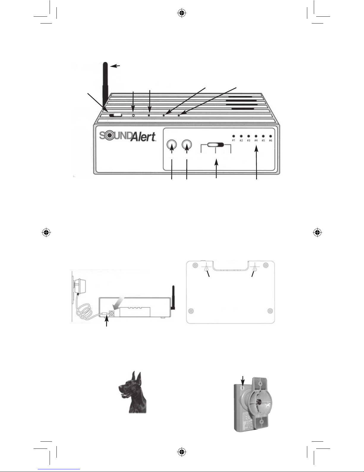
Base Station Controls
5
Base Station Set-Up
Power/
Message
LED
Microphone
hole
Antenna
Set-up
LED
Low Battery
LED
Playback
Button
Volume
Control
Knob
Power
Jack
9VDC end
Power
Adapter
Slide Switch with
Run, Record &
Program positions
Message
Buttons
On/Off
Switch
Pre-Recorded Messages
SoundAlert comes with the following
Pre-recorded messages:
1. “Driveway”
2. “Front Door”
3. “Backdoor”
4. Ding Dong
5. Buzzer
6. Barking Dog
Your SA12 comes with 2 Sensor/
Transmitters (SA24 comes with 4
Sensor/Transmitters) The’re labeled
on the back with a number that corre-
sponds to the prerecorded message.
For example, the
sensor with #1 on
back will announce
“driveway” for
each detection.
Playback Volume RUN RECORD PROGRAM
OFF ON MIC PWR/MSG SETUP LOW BATTERY
Keyholes slide over screws
for Wall Mounting
Why the RAB SoundAlert System is Right for You
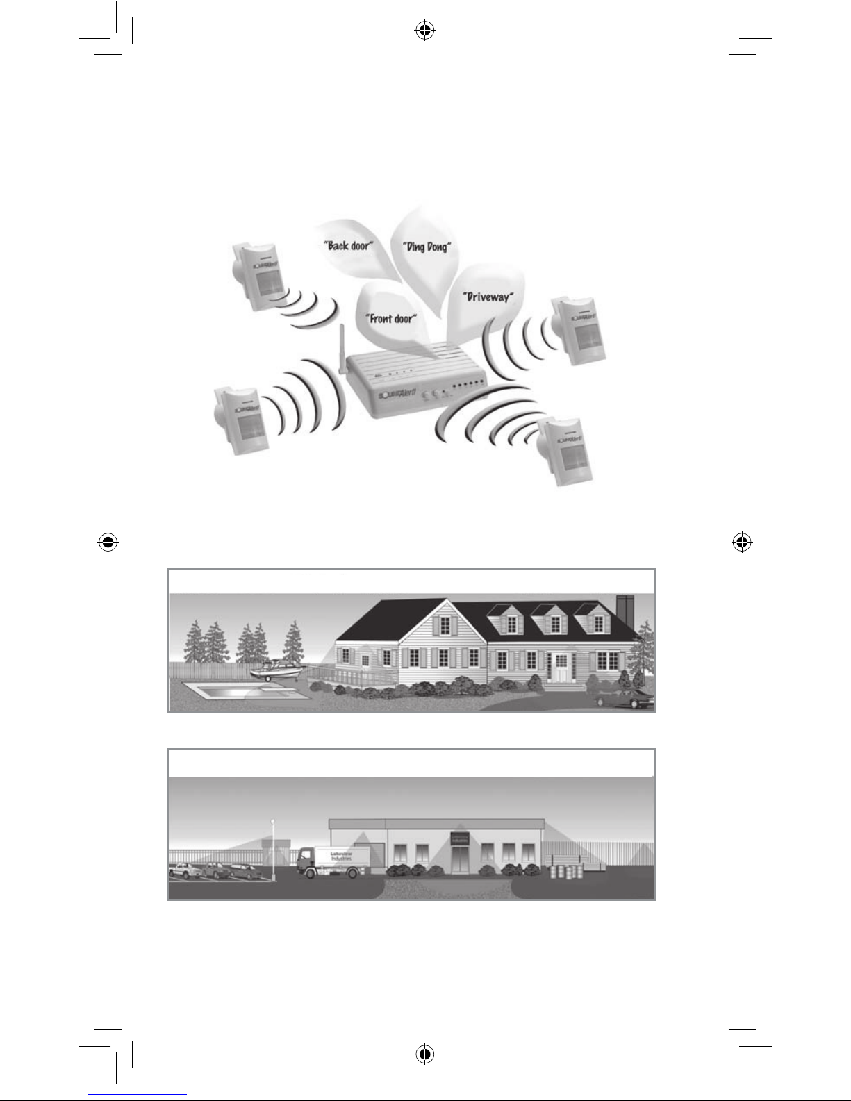
It tells you when and where someone’s coming.
Simply put the wireless Sensor/Transmitters wherever you want and you
will be notified by a voice message when activity has been sensed in that
area. It’s the easiest and most thorough monitoring device you will ever
own!
Great for Home or Business!
It’s like having a 24/7 security staff that never sleeps.
Add motion activated detection all around your home and business.
“Pool” “Boat” “Back Door” “Front door” “Driveway”
“Parking “Storage “Loading “Main “Outdoor “North
area” area” dock” entrance” storage area” fence”
Residential
Commercial
4
SA Manuel.indd 4 4/29/05 3:06:46 PM
Page 5
Connect Power to the
Base Station
Connect the power adapter included
with your SoundAlert System to a
suitable standard wall receptacle
(120 VAC, 60 Hertz power outlet). Plug
the 9VDC end into the power jack on
the SoundAlert Base Station rear panel.
Wall Mounting Base Station
Screw in 2 screws 4 5/16” apart on a
level plane, making sure to allow screw
heads to protrude 1/8”. Position Base
Station’s keyhole slots over screws and
slide down to secure.Template is
provided for wall attachment.
Base Station Controls
5
Base Station Set-Up
Power/
Message
LED
Microphone
hole
Antenna
Set-up
LED
Low Battery
LED
Playback
Button
Volume
Control
Knob
Power
Jack
9VDC end
Power
Adapter
Slide Switch with
Run, Record &
Program positions
Message
Buttons
On/Off
Switch
Pre-Recorded Messages
SoundAlert comes with the following
Pre-recorded messages:
1. “Driveway”
2. “Front Door”
3. “Backdoor”
4. Ding Dong
5. Buzzer
6. Barking Dog
Your SA12 comes with 2 Sensor/
Transmitters (SA24 comes with 4
Sensor/Transmitters) The’re labeled
on the back with a number that corresponds to the prerecorded message.
For example, the
sensor with #1 on
back will announce
“driveway” for
each detection.
Playback Volume RUN RECORD PROGRAM
OFF ON MIC PWR/MSG SETUP LOW BATTERY
Keyholes slide over screws
for Wall Mounting
5
SA Manuel.indd 5 4/29/05 3:06:46 PM
Page 6
Changing the
Sensor’s Message
Low Battery Reminder
When any of the Sensor/Transmitters
experience a low battery condition, the
“LOWBATTERY” LED will flash on the
top of the Base Station.It will also sound
a pre-recorded Low Battery Message. By
pressing the “PLAYBACK” button, your
“Low Battery Message” will play, as well
as the recorded message identifying the
Sensor/Transmitter that needs battery
replacement.
Missed message LED
Indicator
The missed message LED indicator light
will blink after detection is made.This is
useful if you’ve been away from home.It
alerts you that activity has been detected
in a specific location.
Playback Button &
Message (“MSG”) LED
When a message is triggered by one
or more Sensor/Transmitters, the
“PWR MSG” LED will flash, notifying
you that a trigger has occurred. By
pressing the “PLAYBACK”button, each
message that was triggered will play.
The system will then clear the triggered messages and the “PWR
MSG” LED will stop flashing. This is
helpful in the event that you miss
hearing the message because you
weren’t near the base station or you
were away from home when it was
activated.
6
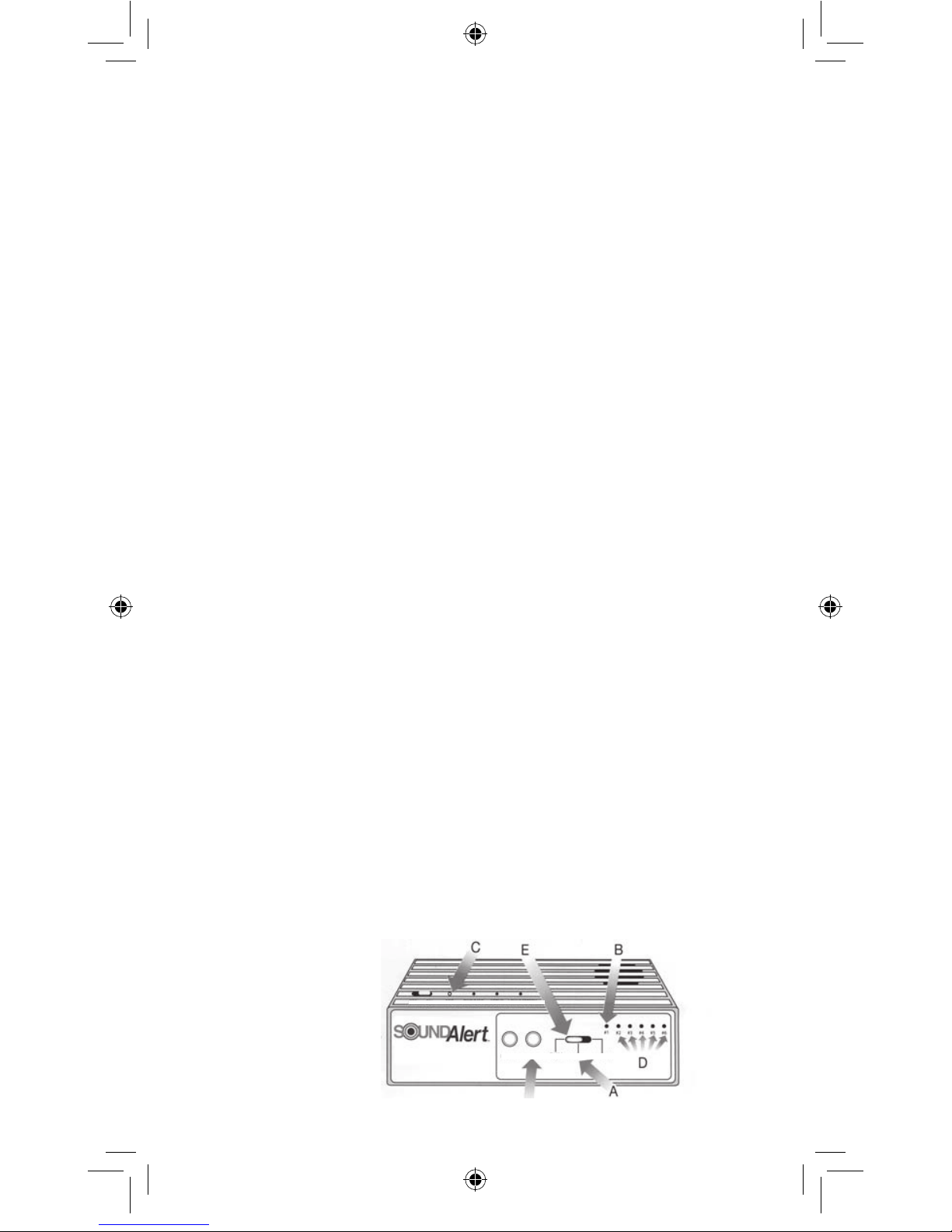
To Record Your Own
Voice Messages
1. Turn ON the Base Station with the
ON/OFF switch on the top of the unit.
Power/Message LED light will glow.
2.The front of the Base Station has one
slide switch and 6 message buttons. To
record a voice message, select the
middle position of the slide switch
marked “RECORD” (See “A” below).
3. Push and hold message button #1 (B)
and talk into the “MIC” hole (C).The
“SETUP” LED will glow as long as the
message button is held down to record a
message of up to 6 seconds.
4. To record a message on buttons
#2-#6, repeat steps 2-3 using each
message button (D).
5. To change a message, repeat steps 2-3.
6. Return the slide switch to the “RUN”
position (E).
7. In the “RUN” mode, push a message
button to playback the voice message
just recorded.You may test each of the
message buttons this way.
8. Set the desired volume with the
volume control knob (F) on the front of
the Base Station.
1. Move the slide switch on the front of
the Base Station to “PROGRAM”.
2. Press and hold the number of the
message that you require (for example,
if you want the sound of a barking dog,
press and hold #6 for 2 seconds.
3. Activate the Sensor/Transmitter by
moving your hand in front of the lens and
observing the LED flashing on the front.
4.Return slide switch to “RUN” position.
5.Test the Sensor/Transmitter by
moving your hand in front of the lens.
message
buttons
OFF ON MIC PWR/MSG SETUP LOWBATTERY
Playback Volume RUN RECORD PROGRAM
F
Sensor/Transmitter
Battery Saving Option
To extend the life of your battery, you
may disable the red LED that glows
through the front of the Sensor/
Transmitter. Move the W1 switch (A)
(see Diagram 1) to the “OFF” position.
Activating Switch Contacts
You can use your SoundAlert Sensor/
Transmitter to activate switch contacts
that will transmit to the Base Station.
This would be used, for example, if
you want a doorbell to activate one of
your recorded base station messages.
1. Move the switch on “SW2” to OFF
position (C) (see Diagram 2).This
deactivates sensor.
2.Use a small screwdriver to open dry
contacts (E) on the terminal block (D).
3.Insert the two wires from your
switch contact into the terminal block.
Setting the
Message Delay
Installing the
Sensor/Transmitter
9 Volt Battery
Remove the front cover of the
SoundAlert Sensor/Transmitter by
pressing down on the release tab at
the bottom of the unit (See below).
Connect a 9-volt alkaline battery to
the connector and replace the cover.
NOTE:When closing the sensor, be
sure to position the gasket carefully
to insure weatherproofing.
Setting up the Sensor/Transmitter
BATTERY
The VR1 (B) (see Diagram 1) sets
the sensor delay. This is the time
between voice announcements. For
example, if the sensor delay is set for
3 minutes (maximum), there will be
3 minutes between voice announce-
ments; regardless of how many
times a person has been detected.
A
Adjusts
Time
Delay
Diagram 1
Diagram 2
C
D
E
Turns
off
LED
To set the time delay, use a small
screwdriver to turn the adjusting screw
clockwise for longer time delay,
counter clockwise for shorter delay.
Message delay is factory set for
0 minutes.
Set Up Mode: Voice announcement
is played each time the sensor/trans-
mitter is triggered by movement.
Operational Mode: Voice announce-
ment is played once and waits for the
time you set on the time delay, checks
the protected zone and transmits again
only if movement is still detected.
B
6
SA Manuel.indd 6 4/29/05 3:06:47 PM
Page 7
Sensor/Transmitter
Battery Saving Option
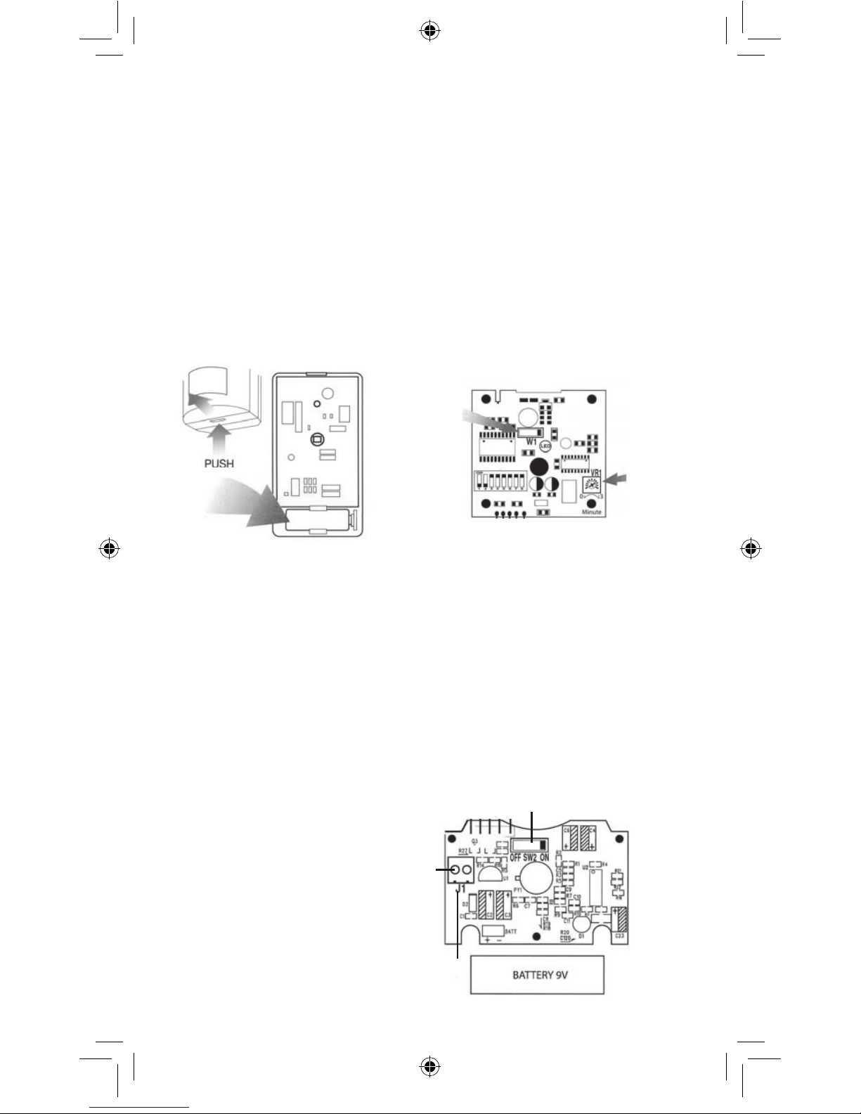
To extend the life of your battery, you
may disable the red LED that glows
through the front of the Sensor/
Transmitter. Move the W1 switch (A)
(see Diagram 1) to the “OFF” position.
Activating Switch Contacts
You can use your SoundAlert Sensor/
Transmitter to activate switch contacts
that will transmit to the Base Station.
This would be used, for example, if
you want a doorbell to activate one of
your recorded base station messages.
1. Move the switch on “SW2” to OFF
position (C) (see Diagram 2).This
deactivates sensor.
2.Use a small screwdriver to open dry
contacts (E) on the terminal block (D).
3.Insert the two wires from your
switch contact into the terminal block.
Setting the
Message Delay
Installing the
Sensor/Transmitter
9 Volt Battery
Remove the front cover of the
SoundAlert Sensor/Transmitter by
pressing down on the release tab at
the bottom of the unit (See below).
Connect a 9-volt alkaline battery to
the connector and replace the cover.
NOTE:When closing the sensor, be
sure to position the gasket carefully
to insure weatherproofing.
Setting up the Sensor/Transmitter
BATTERY
The VR1 (B) (see Diagram 1) sets
the sensor delay. This is the time
between voice announcements. For
example, if the sensor delay is set for
3 minutes (maximum), there will be
3 minutes between voice announcements; regardless of how many
times a person has been detected.
A
Adjusts
Time
Delay
Diagram 1
Diagram 2
C
D
E
Turns
off
LED
To set the time delay, use a small
screwdriver to turn the adjusting screw
clockwise for longer time delay,
counter clockwise for shorter delay.
Message delay is factory set for
0 minutes.
Set Up Mode: Voice announcement
is played each time the sensor/transmitter is triggered by movement.
Operational Mode: Voice announcement is played once and waits for the
time you set on the time delay, checks
the protected zone and transmits again
only if movement is still detected.
B
7
SA Manuel.indd 7 4/29/05 3:06:47 PM
Page 8
Sensor/Transmitter
Wall Mounting
Indoors
Wall Mount
Test the Sensor/Transmitter for
range and correct operation before
permanent installation
If the Base Station doesn’t respond,
check that it has been properly programmed to respond to the Sensor/
Transmitter or relocate the Sensor/
Transmitter to a different location,
possibly closer to the Base Station,
and test again. Refer also to the Base
Station Operating Instructions for
troubleshooting tips.
Installation indoors, on a smooth
surface, can be accomplished with
the double sided tape included with
each SoundAlert Sensor/Transmitter.
Simply peel off one side of the tape
and apply it to the back of the
Sensor/Transmitter mounting bracket.
Peel off the second side of the tape
and press the mounting bracket tape
to the smooth surface or use the
screws provided.
Outdoors
Screws (included) are recommended
for installing the Sensor/Transmitters
outdoors, on rough surfaces, or where
there is the possibility of high winds.
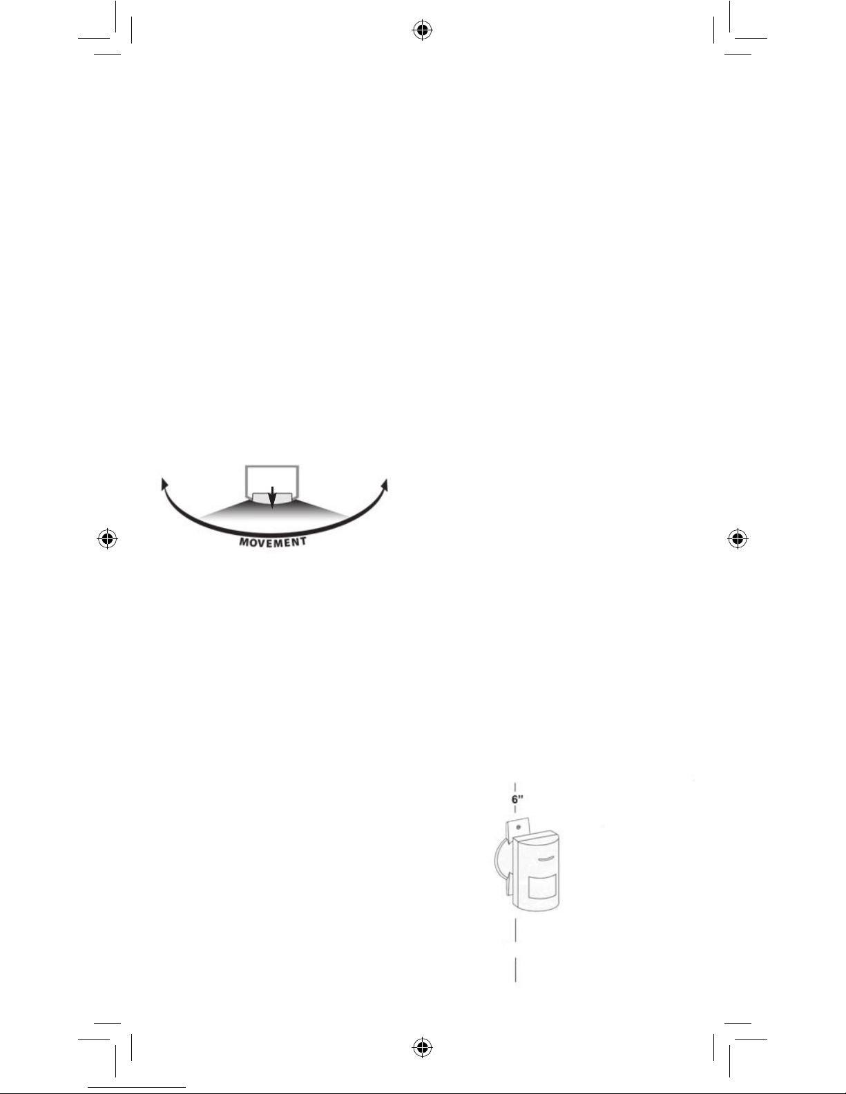
Securely install the mounting bracket
at the desired location. The sensor
should be placed approximately 7
feet above the floor for maximum
range of detection (see diagram
below).
7 feet
Choosing the best
Location for your
Sensor/Transmitter
Avoid Direct Sunlight
The Sensor/Transmitter should not
be placed where sunlight will shine
directly on the face of the Sensor/
Transmitter, (Indirect light through
windows will not trigger the sensor).
Avoid hot and cold air currents
Install the Sensor/Transmitter at
least 3 feet from strong forced air
heaters, air conditioners or sources
of drafts, such as doors.
Choose a location at right angles to
the path of movement
The Sensor/Transmitter functions
best when placed so that movement is across the detection patterns, rather than toward the sensor.
Avoid Obstructions
Place the Sensor/Transmitter so
that no large objects obstruct the
detection pattern. Trees and other
moving objects like flags can
cause false triggers.
Install the Sensor/Transmitter
straight up and down
Installing the unit tilted slightly
forward will reduce the detection
range of the Sensor/Transmitter.
Avoid installing the Sensor/
Transmitter on metal surfaces.
Metal surfaces, such as aluminum
siding, will reduce the radio signal
transmission range of the
Sensor/Transmitter, unless it is
installed near the edge of a window.
Weather resistance
Make certain to reposition the rubber
gasket around the edge of the
Sensor/Transmitter carefully when
reattaching the Sensor/Transmitter
cover.
Top View
Front of
sensor
8
Sensor/Transmitter
Pattern Adjustment
Choose the pattern for your
Sensor/Transmitter to meet the needs
of each monitored zone.The
Sensor/Transmitter comes set from
the factory with a fan pattern (A) that
covers a 40’x 40’area, when mounted
at 8’ above the ground. Use one of
the flexible Pattern Adjusting inserts
(included) to choose the pattern for
either a vertical fan pattern (B) or a
horizontal fan pattern (C).
To install a pattern adjuster
1. Remove the sensor cover.
2. Insert one edge of the plastic
pattern adjuster (D) into the frame
behind the lens.
3. Gently press the pattern adjuster
until the other edge snaps into the
opposite side of the lens frame.
4. Make sure to carefully position the
sensor cover gasket when closing
cover to insure weatherproofing.
A
A
B
B
C
C
Side View
8
SA Manuel.indd 8 4/29/05 3:06:48 PM
Page 9
Sensor/Transmitter
Pattern Adjustment
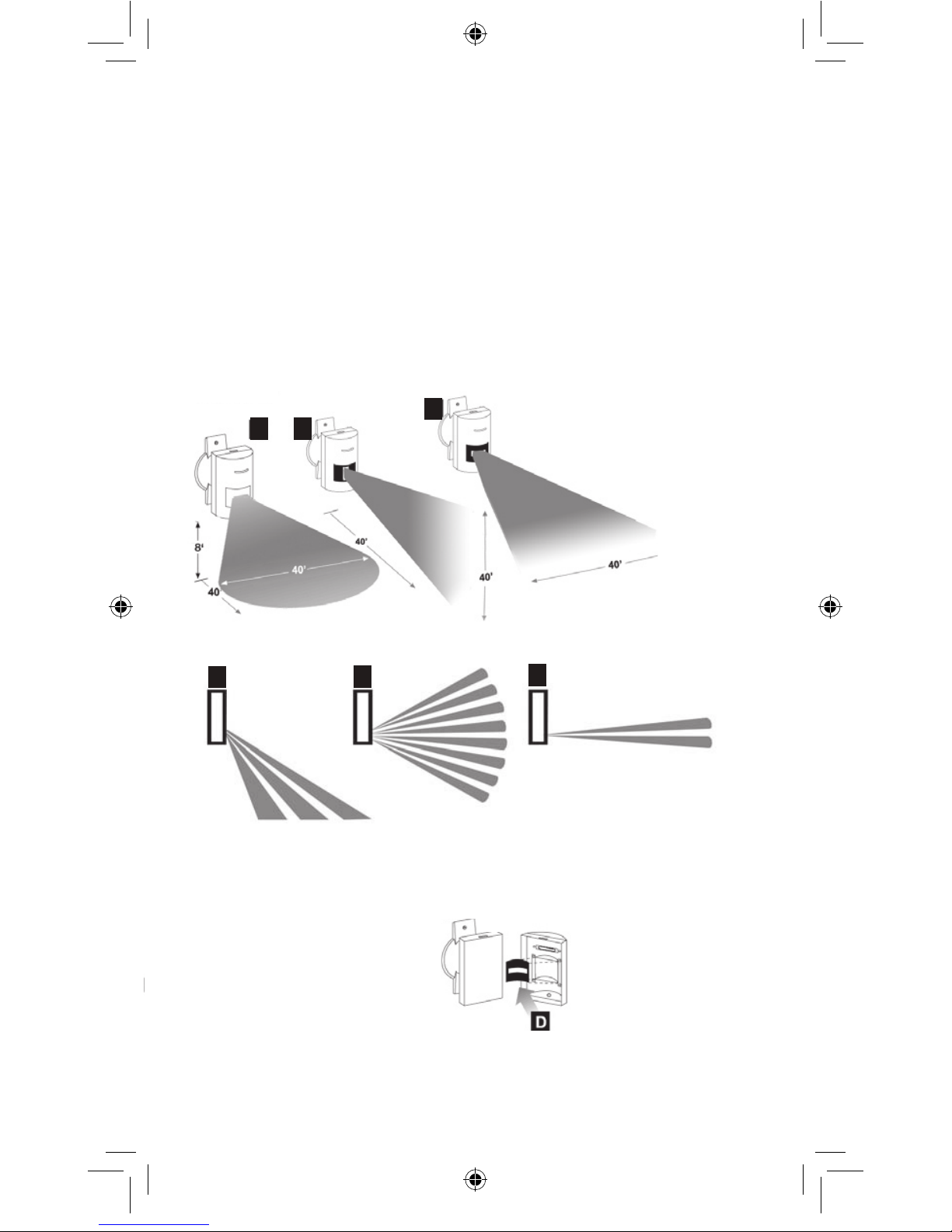
Choose the pattern for your
Sensor/Transmitter to meet the needs
of each monitored zone.The
Sensor/Transmitter comes set from
the factory with a fan pattern (A) that
covers a 40’x 40’area, when mounted
at 8’ above the ground. Use one of
the flexible Pattern Adjusting inserts
(included) to choose the pattern for
either a vertical fan pattern (B) or a
horizontal fan pattern (C).
To install a pattern adjuster
1. Remove the sensor cover.
2. Insert one edge of the plastic
pattern adjuster (D) into the frame
behind the lens.
3. Gently press the pattern adjuster
until the other edge snaps into the
opposite side of the lens frame.
4. Make sure to carefully position the
sensor cover gasket when closing
cover to insure weatherproofing.
A
A
B
B
C
C
Side View
9
SA Manuel.indd 9 4/29/05 3:06:48 PM
Page 10
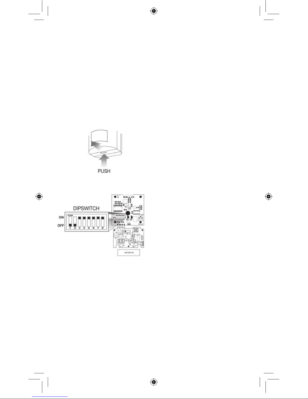
The Sensor/Transmitter included in
the SoundAlert kit comes preprogrammed from the factory and will
activate any Base unit within range.
If you decide to isolate a Sensor/
Transmitter to one receiver only or
change the Code, follow these
steps:
1. Remove the front cover of the
Sensor/Transmitter by pressing
down on the release tab at the top
of the unit.
2. To change the code, set the 8-key
dipswitch to any setting different from
your other Sensor/Transmitter settings.
3. The new code setting must be
programmed into the Base Station
(see page 11 for detailed information).
4. If activating the same message is
desired for any number of additional
Sensor/Transmitters, set the dipswitch
of each Sensor/Transmitter to the
SAME code positions. Programming
of the SoundAlert Base Station is not
necessary for these additional
Sensor/Transmitters, if the original
codes have already been
programmed.
Changing the Sensor/
Transmitter code
Programming
Sensor/Transmitters to
Activate Additional
Messages
The Sensor/Transmitters included in the
SoundAlert kits are pre-programmed from
the factory and will function without modification. If you decide to change the code
or add more Sensor/ Transmitters, follow
these steps:
1. Connect the SoundAlert Base Station
to a power source and turn the unit “ON”
with the “POWER”switch.
2.The Base station has a 3 position slide
switch. Move the switch to the
“PROGRAM” position
3. Set the 8 dipswitches in any setting
DIFFERENT from your other
Sensor/Transmitter settings.
4. Activate the Sensor/Transmitter
by moving your hand in front of the
lens and observing the LED flashing
on the front. (The Base Station
“SET UP” LED will glow, indicating
that the transmission has been
received).
5. While the “SET UP” LED is glowing,
press the button for the message that
you want activated by that Sensor/
Transmitter, #1-#6.The “SET UP”
LED light will stop glowing, indicating
that the Sensor/Transmitter is now
programmed to activate the selected
voice message.
6. Return the slide switch to the
“RUN” position.
7. Repeat steps 2 through 4 to program
additional Sensor/Transmitters to
each voice message.
Note: Any number of
Sensor/Transmitters can be set to
activate the same message by
setting it to the same dipswitch code.
How to set-up the X-10,
Leviton, or Lutron RadioRa
Interface
You can control lights or other
devices with your SoundAlert by
using a module provided by others
(X-10, Leviton and Lutron RadioRa).
There are four C relay outputs on the
bottom of the Base Station.
When a Sensor/Transmitter is trig-
gered, you have the option of also
triggering a module (such as the
X-10 Powerflash) attached to one of
these dry contact relay outputs.
The four relayl outputs (labeled
NO.1 thru NO.4) correlate to Zones
#1 thru #4.
Each contact has three outputs.
The one on the left is NO (normally
open), the middle is a common
ground, and the one on the right is
NC (normally closed).
Contacts are rated to carry 24 VDC
or 117 VAC at 1 AMP.
If you want to trigger a desk lamp,
for example (in addition to playing
the voice message) when the
Sensor for Zone #1 detects move-
ment, you must insert wire (not
supplied) from the module into one
of the Base Station output terminals
as shown below.
Then plug the lamp into the module.
One of the wires is placed in the
"middle" or common output of
NO.1 on the bottom of the Base
Station. The other wire goes into the
NO (open) or NC (closed) output
directly to the left or right depending
on the operation you require.
If you plug the other wire into the
NC (normally closed) contact, a
triggering of the sensor forces the
circuit open, breaking the circuit. In
the desk lamp example, this turns
the module and the lamp off.
If you plug the other wire into the
NO (normally open) contact, a trig-
gering of the sensor forces the
contacts together, initiating a circuit.
In the desk lamp example, this
turns the module and the lamp on.
(X-10
Powerflash
module
available
from others)
NO
(Normally Open)
NC
(Normally Closed)
Common Ground
10
SA Manuel.indd 10 4/29/05 3:06:49 PM
Page 11
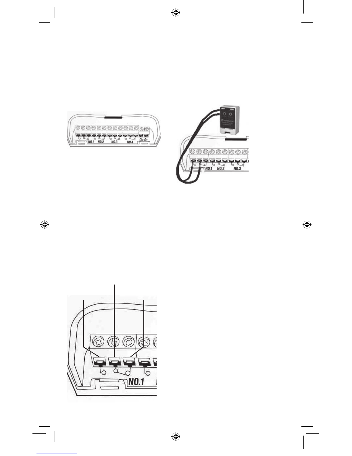
How to set-up the X-10,
Leviton, or Lutron RadioRa
Interface
You can control lights or other
devices with your SoundAlert by
using a module provided by others
(X-10, Leviton and Lutron RadioRa).
There are four C relay outputs on the
bottom of the Base Station.
When a Sensor/Transmitter is triggered, you have the option of also
triggering a module (such as the
X-10 Powerflash) attached to one of
these dry contact relay outputs.
The four relayl outputs (labeled
NO.1 thru NO.4) correlate to Zones
#1 thru #4.
Each contact has three outputs.
The one on the left is NO (normally
open), the middle is a common
ground, and the one on the right is
NC (normally closed).
Contacts are rated to carry 24 VDC
or 117 VAC at 1 AMP.
If you want to trigger a desk lamp,
for example (in addition to playing
the voice message) when the
Sensor for Zone #1 detects movement, you must insert wire (not
supplied) from the module into one
of the Base Station output terminals
as shown below.
Then plug the lamp into the module.
One of the wires is placed in the
"middle" or common output of
NO.1 on the bottom of the Base
Station. The other wire goes into the
NO (open) or NC (closed) output
directly to the left or right depending
on the operation you require.
If you plug the other wire into the
NC (normally closed) contact, a
triggering of the sensor forces the
circuit open, breaking the circuit. In
the desk lamp example, this turns
the module and the lamp off.
If you plug the other wire into the
NO (normally open) contact, a triggering of the sensor forces the
contacts together, initiating a circuit.
In the desk lamp example, this
turns the module and the lamp on.
(X-10
Powerflash
module
available
from others)
NO
(Normally Open)
NC
(Normally Closed)
Common Ground
11
SA Manuel.indd 11 4/29/05 3:06:50 PM
Page 12
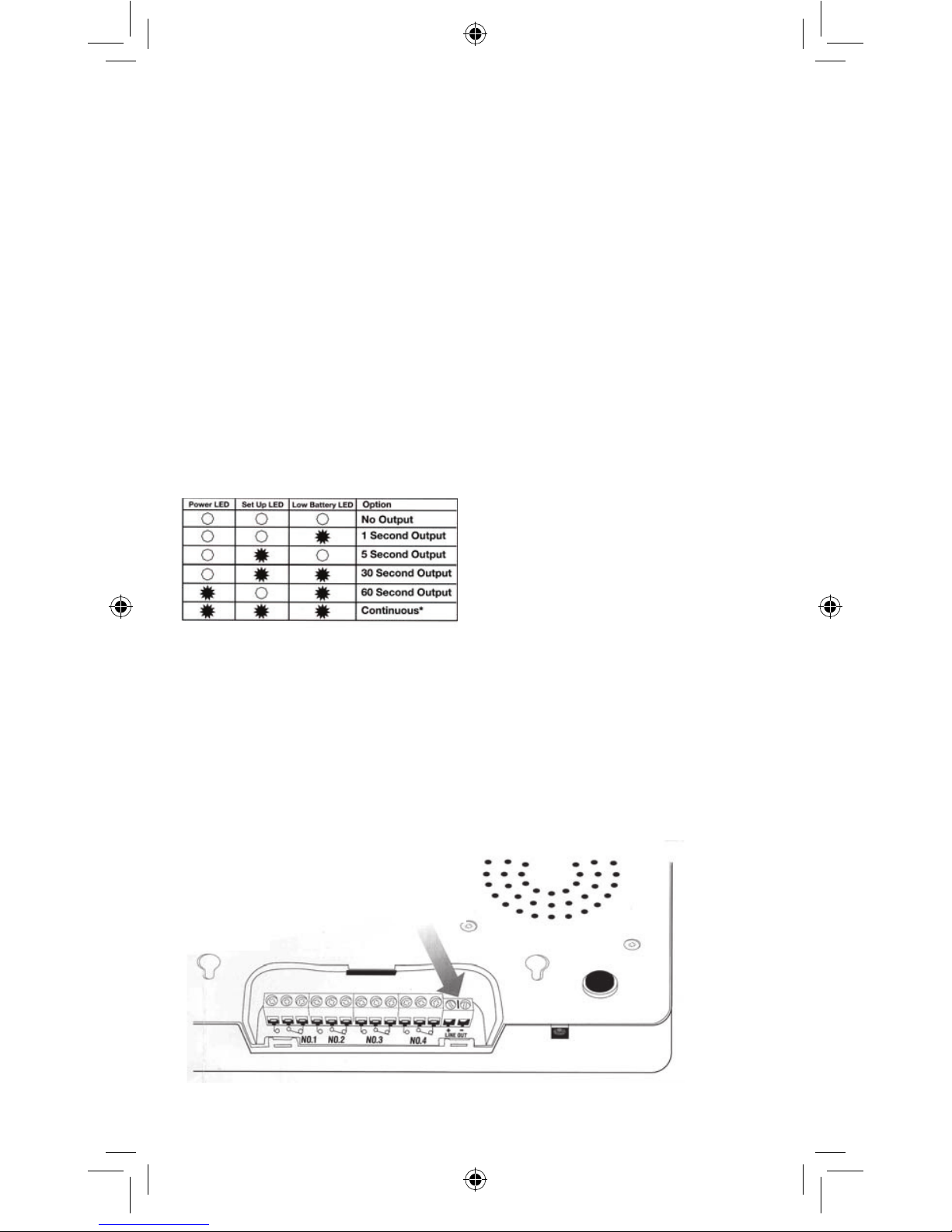
Base Station
Bottom
For the Hearing Impaired
Recorded messages can be heard
from an intercom or Public Address
system by connecting the amplifier
to the LINE OUT terminals located in
the compartment under the Base
Station (See below).
Use the volume control of the
amplifier, NOT the “Volume” knob on
the SoundAlert Base Station.
To set the output duration
of each connection:
1. Move the slide switch to the
“RUN” position.
2. Press and hold the “PLAYBACK”
button for 2 seconds to activate
SETUP MODE.
3. In SETUP MODE, toggle
through the setting sequence for
each message button #1 - #4 to set
the output duration for each terminal
output connection. The three LED’s
will indicate the time duration
setting (see chart below).
4. Press the “PLAYBACK” button to
lock in each chosen setting and
return to operating mode.
5. Repeat steps 1,2,3 and 4 to set
time duration for each connection.
Note: To disarm the SoundAlert
System when the “CONTINUOUS”
setting is triggered, turn OFF the
Base Station with the “POWER”
switch. When “POWER” is turned
back ON, the system will return to
operating mode.
LINE OUT
Terminals
12
SA Manuel.indd 12 4/29/05 3:06:50 PM
Page 13

No Sound
• Check the “POWER” switch on
your Base Station. RIGHT is ON,
LEFT is OFF.
• The slide switch on the Base
Station must be in the “RUN”
position.
• Turn up the volume control knob
of the Base Station.
• Check the AC adapter. It must be
properly connected to the Base
Station and an active wall receptacle.
• Test the message by pushing the
appropriate message button located
on the Base Station.
• A Sensor/Transmitter must have
been programmed to activate the
voice message. If the program of
the Base Station gets deleted, you
must follow the instructions on
Page 10 (Programming One or
More Sensor/Transmitters to
Activate Additional Messages).
The Sensor/Transmitter will
not operate SoundAlert
• Check the Sensor/Transmitter 9
volt battery.
• Check the power connection to
the Base Station.
• Follow steps on Pages 7-11
(Sensor/Transmitter Installation).
• Make sure the steps are followed
on Page 10 (Programming One or
More Sensor/Transmitters to
Activate Additional Messages).
VERY IMPORTANT: If the Base
Station “SET UP” LED does not
glow, the Sensor/Transmitter was
not programmed and the proce
dure will have to be repeated.
Poor Distance
• Check the Sensor/Transmitter
battery.
• Check the Base Station DC
Power source.
• Check the Base Station with a
different Sensor/Transmitter.
• Check that the Sensor/Transmitter
is not fastened to metal. Move the
Base Station about 1 foot in any
direction.
Cannot Record a Message
• Turn on Base Station power
• Turn the volume control up
• Make sure that the slide switch of
the Base Station is in “RECORD”
position.
• Check the connection to the Base
Station power.
Cannot Playback a Message
• Turn the volume control up
• Make sure that the slide switch of
the Base Station is in “RUN” position.
Press the desired message button
(#1-#6)
• Check the connection to the Base
Station power.
Poor Volume
• Turn the volume control up
• Re-record the message with your
mouth a little closer to the micro
phone, (speak loud and clear)
• Check the connection to the Base
Station power.
Playback Distortion
• Reduce the volume control
• Re-record the message with your
mouth a little further from the
microphone
• Check the connection to the Base
Station power.
13
SA Manuel.indd 13 4/29/05 3:06:50 PM
Page 14

Troubleshooting
continued
Message Buttons Won’t
Playback Message
• Make sure the slide switch is in
“RUN” position
• Check the connection to the Base
Station power
Sensor/Transmitter Battery Goes
Dead In A Short Time
• Check that the power saver W1
and VR1 (Page 7, Setting Up The
Sensor/Transmitter Battery
Savers) have been reset. Adjust
these if necessary and replace
battery with a new one.
Limited Warranty
Your SoundAlert will be promptly
replaced or repaired, at our option, if it
proves to be defective in workmanship
or materials within 1 year of purchase.
For repair or replacement, please call
the Tech Help Line at 888 RAB-1000
for instructions.
If your SA12 or SA24 kit is out of
warranty or damage is unrelated to its
original manufacture, return your
unit freight prepaid to the address
on the back of this manual. Please
include a description of the problem
and a check for $75. for the SA12
kit or $100. for the SA24 kit (made
out to RAB Lighting). We will repair
or replace your unit promptly.
Under no circumstances shall RAB
be liable for any incidental or conse-
quential damages arising out
of or in connection with the use or
performance of this product or other
indirect damages with respect to loss
of property or revenue or cost of
installation, removal or re-installation.
This warranty gives you specific legal
rights and you may also have other
rights which vary from state to state.
SoundAlert is designed to detect
people or cars in the detection area.
It should not be construed as a theft
or crime prevention device. RAB
does not accept responsibility for any
damages resulting from intrusion or
other crimes.
Toll Free
Technical Assistance
If you need technical assistance,
please do the following:
1. Re-read the Troubleshooting section
of this manual.
2. Call the Tech Help Line
at 888 RAB-1000, 8AM to 6PM
Eastern Time M-F and we will be glad
to help you.
14
SA Manuel.indd 14 4/29/05 3:06:51 PM
Page 15

Limited Warranty
Your SoundAlert will be promptly
replaced or repaired, at our option, if it
proves to be defective in workmanship
or materials within 1 year of purchase.
For repair or replacement, please call
the Tech Help Line at 888 RAB-1000
for instructions.
If your SA12 or SA24 kit is out of
warranty or damage is unrelated to its
original manufacture, return your
unit freight prepaid to the address
on the back of this manual. Please
include a description of the problem
and a check for $75. for the SA12
kit or $100. for the SA24 kit (made
out to RAB Lighting). We will repair
or replace your unit promptly.
Under no circumstances shall RAB
be liable for any incidental or consequential damages arising out
of or in connection with the use or
performance of this product or other
indirect damages with respect to loss
of property or revenue or cost of
installation, removal or re-installation.
This warranty gives you specific legal
rights and you may also have other
rights which vary from state to state.
SoundAlert is designed to detect
people or cars in the detection area.
It should not be construed as a theft
or crime prevention device. RAB
does not accept responsibility for any
damages resulting from intrusion or
other crimes.
Toll Free
Technical Assistance
If you need technical assistance,
please do the following:
1. Re-read the Troubleshooting section
of this manual.
2. Call the Tech Help Line
at 888 RAB-1000, 8AM to 6PM
Eastern Time M-F and we will be glad
to help you.
15
SA Manuel.indd 15 4/29/05 3:06:51 PM
Page 16

16
Tech Help Line Fax Back Website e-mail
888 RAB-1000 888 RAB-1236 www.rabweb.com [email protected]
170 Ludlow Avenue, Northvale, NJ 07647 USA
30 warehouses nationwide.
SA Manuel.indd 16 4/29/05 3:06:51 PM
 Loading...