

Page 1
SMART SWITCH OCCUPANCY SENSOR
Installation Manual
Features
Maximum Energy savings
• Sensitive 180ºview passive
infrared motion detector keeps
lights on only when rooms are in
use.
• No ON switch so lights are never
left on by mistake.
• Meets California Title 24 standards.
• Suitable for all utility rebate
programs
Maximum Coverage
• 180ºwide angle detection pattern
• Picks up people entering door-
ways quickly with standard next
to doorway location.
• Covers 1000 square feet, eliminates
needs for multiple sensors.
• Su
perb small movement sensitivity
within 18 feet. Great for sedentary
office use.
• No dead spots with 18 sensing
fingers.
Easy Installation
• Works with electronic ballasts.
• No minimum load requirement.
• R
eplaces single pole wall switches
without additional wiring.
• Decorator style, rectangular
switchplate included.
• Only 1/2” protrusion from switch
plate.
• N
o adjustments required for most
installations.
• Compact design fits standard
switch boxes with plenty of room
for wiring.
• Tamperproof control panel cover
reduces call backs for tampering.
Maximum Versatility
• S
witches all types of fluorescent
and/or incandescent lighting.
• Fits single or multi-gang locations
without special adapters.
1
Page 2

Specifications
Coverage:
1000 square feet,
up to 32’ from the sensor
Detection Zone:
180ºin 18 zones
32’ range
Detection Pattern:
Note:
Detection of sedentary small movement (desk work) within 18’
Time Adjustment:
8 seconds to 15 minutes
after motion stops (approximate)
Detection Indicator:
Red LED
Energy Codes:
Complies with California Title 24
Switching Capacity:
120v: 800w Incandescent &
Fluorescent
277v: 1200w Incandescent &
Fluorescent
Minimum Load:
None
Power Consumption:
Negligible
Wiring:
Replaces single pole wall switch,
3 wire system where neutral & hot
are present.
Temperature Range:
-4ºF to +104ºF
(-20ºC to +40ºC)
Humidity Range:
93% relative humidity
Approvals:
UL Listed Photocontrol
UL Standard 773A
Weight:
3.3 oz. (no box)
Parts List:
LOS800 Sensor
Matching Wall Plate
2 matching wall plate screws
2 sensor mounting screws
Dimensions:
A=4.06” (103mm) B=1.69” (43mm)
C=2.25” (57mm) D=2.56” (65mm)
E=1.25” (32mm) F=.5” (13mm)
G=1.68” (43mm)
A D
B
E
C
G
F
5’
32’
Side View 32’
Locate the LOS800 where it has
an unobstructed view of the room,
particularly the areas normally
occupied by people. Ideal mounting height is 3.5 to 4.5 feet above
the floor.
If people cannot see the sensor
lens from their normal positions in
the room, the sensor will not detect
their presence.
High cabinets, walls, doors and
other obstructions may limit the
sensor’s view of the entire room. If
obstructions can be moved the
sensor will have a better view. If
the areas obstructed are not areas
normally occupied, the sensor will
s
till be able to see normal occupancy.
Cabinet obstructs sensor’s
view of active area
Obstruction moved, sensor
has full view
If t
he room is L shaped or the sensor’s
view is badly obstructed from the
door switch location, use the
LOS2500 ceiling mounted sensor
instead of the LOS800.
Ceiling mounted LOS2500
sensor with 360º detection
Do not locate sensor over or looking
at heating vents, baseboard
heaters, hanging plants or air
conditioners.
Do not locate sensor where it will
view direct sunlight.
If the sensor’s location gives it a
v
iew of the other rooms or hallways,
lights will be turned on when
movement is detected in these
adjacent areas. If this is undesirable,
the sensor’s detection zone may
be restricted by covering a portion
of the lens with a white paper label
or tape.
Sensor has view of
adjacent area
Selecting A Location
1
Sensor
Sensor
S
ensor
Top View 50’
50’
2 3
Page 3

Installation Step by Step
1. Remove the existing switch, if
necessary.
2. Connect as shown in the wiring
diagrams. See page 3.
3. Twist on wire nuts. Secure with
electrical tape. Mount LOS800 in
wall box with two screws provided.
4. Place switch in OFF position
before turning on power.
5. Press the Auto/Off switch IN to
“Auto”. After a short delay, the
lights will turn ON. When the room
is vacated, the lights will turn OFF
after the time delay you set.
6. See “Adjustments” section for
control options. Only make adjustments after a 3 minute warmup
period.
7. Attach the wall plate.
Installation
2
WALL MOUNTING BOX
ADJUSTMENT
ACCESS COVER
(Removable only
when switch plate
is off)
Black
Red
White
Black
Caution:
• TURN OFF ALL POWER BY
REMOVING THE POWER FUSES
OR TURNING OFF THE CIRCUIT
BREAKER FOR YOUR SAFETY
AND TO PREVENT DAMAGE TO
THE UNIT.
• Please read this entire Owner’s
Manual before installing.
• All wiring should comply with
local electrical codes and requires
a qualified electrician.
• Make sure the total lighting load
connected to the LOS800 does not
exceed the following:
120v: 800w Incandescent &
Fluorescent
277v: 1200w Incandescent &
Fluorescent
Exceeding the wattage limits may
damage the unit. To switch more
wattage, an electrician can install a
relay to handle the load.
• Do not use LOS800 to control
high intensity discharge lights,
fans, heaters or motors. Small
bathroom exhaust fans may be
used with LOS800.
• The LOS800 may be used with
both standard and electronic
fluorescent ballasts.
Basic Wiring Diagram
Single Level Lighting
Multiple Level Lighting
Wiring Diagram
Caution:
• TURN OFF ALL POWER BY
REMOVING THE POWER FUSES
OR TURNING OFF THE CIRCUIT
BREAKER FOR YOUR SAFETY
AND TO PREVENT DAMAGE TO
THE UNIT.
• The supply ground wire must be
tightly secured to ground.
3-way Switch wiring Diagram
Wiring Diagrams
3
COMMON (WHITE)
HOT (BLACK)
LOAD
RED
RED
BLACK
B
LACK
R
ED
R
ED
BLACK
BLACK/HOT
WHITE/COMMON
COMMON (WHITE)
HOT (BLACK)
LOAD
LOAD
LOAD
LOAD
4
5
Page 4
Field of View Adjustment
If the sensor is “seeing” out
through a doorway into a hallway
or “seeing” undesired areas, simply
cover part of the sensor lens with
o
paque white tape or a paper label.
Clear tape may be used, but it limits
detection only partially.Test that the
portion of the lens covered limits
detection as desired and does not
reduce detection in other areas.
Removing the Adjustment
Access Cover:
This cover is tamperproof and can
not be removed if the switch cover
Plate is attached. The cover has two
“ears” that hook under the cover
plate and prevent tampering. To
remove the cover insert a screwdriver into the latch and pull forward.
Time Delay Adjustment
The time delay adjustment can be
set so the lights turn off from 8
seconds minimum to 15 minutes
maximum after the room is vacated
(approximate).
Walk Test
To test the detection pattern of the
LOS800, make no motion for 30
seconds. Move sideways up to 12”.
The red LED flashes once every 4
seconds when turned on initially
and twice every second to show
detection.
Adjustments
4
Insert small
screwdriver
into slot and
pull forward
Sensor
Sensor has view of
adjacent area
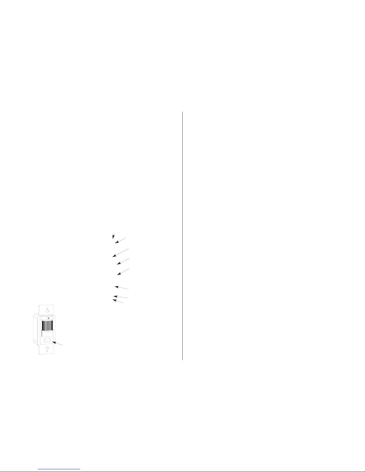
Hole for
Coverplate screw
Mounting screw
Mounting screw
LED for walk
t
esting d
etection
indicator
Motion
Sensor lens
Auto/Off switch
a
uto (
In) Off (Out)
Time delay
(8 second
minimum- 15
m
inu
te maximum)
Turn t
he control
gently c
lockwise
with a s
mall
screw
driver for
more t
ime delay.
Hole for
Coverplate screw.
Over tightening
screw will strip
threads.
5
6
Lights do Not Turn On
1. Check that:
• the lamps and fixtures work;
• wiring exactly matches the
wiring diagram;
• wiring polarity is correct;
• power is on;
• sensor has warmed up for 3
minutes;
• off/auto switch is not OFF
2. Make sure sensor’s view of the
room is not blocked
Lights do Not Turn Off
1. Check that the Time delay control
is set to minimum.
2. Stay completely out of the protection pattern to avoid activation.
3. Make sure sensor is not seeing
move
ment in an adjacent area
through a doorway or other opening.
4. Make sure unit is not aimed at
something that would move or cause
a temperature change such as hot
water pipes, air conditioners or
heating vents.
5. Check that the wattage controlled
does not exceed the maximum limits.
Lights Go On and Off Quickly
1. C
heck that wattage controlled
does not exceed maximum limits.
2. Certain energy saving fluorescent
lamps strobe when turned on within
a minute of being turned off.
Lights Go On for “No Reason”
1. L
ook for sources of electrical
noise such as fans or air conditioners
on the same circuit or nearby. If
possible, unplug or move the noise
sources.
2. Check if sensor is “seeing” into
adjacent rooms or hallways. Mask
sensor lens in that direction with
opaque tape.
3. Check if sensor is “seeing”
heaters or air conditioning vents.
Mask s
ensor lens if necessary.
4. Make sure unit is at room temperature. If it was installed immediately
after being in an extremely hot or
cold environment, wait an hour for it
to adjust.
Troubleshooting
5
6 7
Page 5

An LOS800 Smart Switch requires
no maintenance other than keeping
the lens area clean and free of
obstructions. do not attempt to
open or repair the unit. There are
dangerous voltages inside the case
and no user serviceable parts.
Your LOS800 will be replaced or
repaired, at our option, if it proves
to be defective in workmanship or
materials within one year from the
date of original purchase.
For repair or replacement, return
the product freight prepaid and
insured to the address below.The
LOS800 should be packed carefully.
Please include your sales receipt
and a description of the problem.
If your unit is out of warranty or the
damage is unrelated to its original
manufacture, return your unit
directly to RAB with a check for
$20.00 (payable to RAB Lighting).
We will repair or replace the unit.
Under no circumstances shall we
be liable for any incidental or consequential damages arising out of
or in connection with the use or
performance of this product or
o
ther indirect damages with respect
to loss of property or revenue or
cost of installation, removal or reinstallation. This warranty gives you
specific legal rights and you may
also have other rights which vary
from state to state.
Limited Warranty
Tech Help Line Fax Back Website e-mail
888 RAB-1000 888 RAB-1236 www.rabweb.com [email protected]
170 Ludlow Avenue, Northvale, NJ 07647 USA
Over 30 warehouses nationwide.
8
 Loading...