

Page 1
Smartcat (BL2100)
C-Programmable Single-Board Computer with Ethernet
and Operator Interface
User’s Manual
019–0103_M
Page 2

Smartcat (BL2100) User’s Manual
Part Number 019-0103 • Printed in U.S.A.
©2001–2010 Digi International Inc. • All right s reserved.
Digi International reserves the right to make changes and
improvements to its products without providing n ot ice.
Trademarks
Rabbit, RabbitCore, and Dynamic C are registered trademarks of Digi International Inc.
Rabbit 2000 is a trademark of Digi International Inc.
The latest revision of this manual is available on the Rabbit Web site, www.rabbit.com,
for free, unregistered download.
Digi8 International Inc.
www .rabbi t.com
Smartcat (BL2100)
Page 3

TABLE OF CONTENTS
Chapter 1. Introduction 1
1.1 BL2100 Description..............................................................................................................................1
1.2 BL2100 Features...................................................................................................................................1
1.2.1 Connector Options ........................................................................................................................2
1.3 Optional Add-Ons.................................................................................................................................3
1.4 Development and Evaluation Tools......................................................................................................4
1.4.1 Tool Kit.........................................................................................................................................4
1.4.2 Software........................................................................................................................................5
1.4.3 Online Documentation.............. ... .................................................................................................5
1.5 CE Compliance.....................................................................................................................................6
1.5.1 Design Guidelines.........................................................................................................................7
1.5.2 Interfacing the BL2100 to Other Devices.....................................................................................7
Chapter 2. Getting Started 9
2.1 BL2100 Connections ............................................................................................................................9
2.2 Installing Dynamic C.......................................................................................................................... 14
2.3 Starting Dynamic C ............................................................................................................................15
2.4 Run a Sample Program.......................................................................................................................15
2.4.1 Troubleshooting ..........................................................................................................................15
2.5 Where Do I Go From Here? ...............................................................................................................16
2.5.1 Technical Support.......................................................................................................................16
Chapter 3. Subsystems 17
3.1 BL2100 Pinouts ..................................................................................................................................18
3.1.1 Headers and Screw Terminals..................................................................................................... 19
3.2 Digital I/O...........................................................................................................................................20
3.2.1 Digital Inputs...............................................................................................................................20
3.2.2 Digital Outputs............................................................................................................................21
3.3 Serial Communication ........................................................................................................................23
3.3.1 RS-232 ........................................................................................................................................23
3.3.2 RS-485 ........................................................................................................................................23
3.3.3 Ethernet Port ...............................................................................................................................26
3.3.4 Programming Port.......................................................................................................................27
3.4 Programming Cable............................................................................................................................28
3.4.1 Changing Between Program Mode and Run Mode....................................................................28
3.5 A/D Converter Inputs..........................................................................................................................29
3.6 D/A Converter Outputs.......................................................................................................................30
3.7 Analog Reference Voltage Circuit......................................................................................................31
3.8 Memory...............................................................................................................................................32
3.8.1 SRAM .........................................................................................................................................32
3.8.2 Flash Memory.............................................................................................................................32
3.9 Other Hardware............................................... ....................................................................................33
3.9.1 External Interrupts............................................ ......................................................... ..................33
3.9.2 Clock Doubler.............................................................................................................................34
3.9.3 Spectrum Spreader.............. ........................................................................................................34
User’s Manual
Page 4

Chapter 4. Software 35
4.1 Running Dynamic C........................................................................................................................... 35
4.1.1 Upgrading Dynamic C...................................................... .......................................................... 37
4.1.2 Extras..........................................................................................................................................37
4.2 Sample Programs................................................................................................................................38
4.2.1 Digital I/O...................................................................................................................................38
4.2.2 Serial Communication................................................................................................................ 38
4.2.3 A/D Converter Inputs.................................................................................................................39
4.2.4 D/A Converter Outputs...............................................................................................................39
4.2.5 Using Calibration Constants.......................................................................................................40
4.2.6 Real-Time Clock ......................................................................................................... ............... 40
4.2.7 TCP/IP Sample Programs...........................................................................................................40
4.2.8 LCD/Keypad Module Sample Programs.................................................................................... 40
4.3 BL2100 Libraries ............................................................................................................................... 41
4.4 BL2100 Function APIs.......................................................................................................................42
4.4.1 Board Initialization..................................................................................................................... 42
4.4.2 Digital I/O...................................................................................................................................43
4.4.3 Serial Communication................................................................................................................ 45
4.4.4 A/D Converter Inputs.................................................................................................................46
4.4.5 D/A Converter Outputs...............................................................................................................50
Chapter 5. Using the TCP/IP Features 55
5.1 TCP/IP Connections...........................................................................................................................55
5.2 TCP/IP Sample Programs...................................................................................................................57
5.2.1 How to Set IP Addresses in the Sample Programs..................................................................... 57
5.2.2 How to Set Up Your Computer for Direct Connect................................................................... 58
5.2.3 Run the
5.2.4 Running More Demo Programs With a Direct Connection ....................................................... 60
5.3 Where Do I Go From Here?............................................................................................................... 60
PINGME.C Demo......................................................................................................59
Appendix A. Specifications 61
A.1 Electrical and Mechanical Specifications..........................................................................................62
A.1.1 Exclusion Zone.......................................................................................................................... 64
A.1.2 Headers...................................................................................................................................... 65
A.2 Conformal Coating............................................................................................................................ 66
A.3 Jumper Configurations ........................... ........................................................... ................................67
A.4 Use of Rabbit 2000 Parallel Ports .....................................................................................................69
A.5 I/O Address Assignments.................................................................................................................. 71
Appendix B. Power Supply 73
B.1 Power Supplies.............................................................................. ....................................................73
B.1.1 Power for Analog Circuits.........................................................................................................73
B.2 Batteries and External Battery Connections......................................................................................74
B.2.1 Replacing the Backup Battery ....................................... ............................................................ 75
B.2.2 Battery-Backup Circuit.............................................................................................................. 75
B.2.3 Power to VRAM Switch............................................................................................................ 76
B.2.4 Reset Generator..........................................................................................................................76
B.3 Chip Select Circuit.............................................................................................................................77
Appendix C. LCD/Keypad Module 79
C.1 Specifications.......................................... ...........................................................................................79
C.2 Contrast Adjustments for All Boards ............................................ ....................................................81
C.3 Keypad Labeling................................................................................................................................82
C.4 Header Pinouts...................................................................................................................................83
C.4.1 I/O Address Assignments .......................................................................................................... 83
C.5 Mounting LCD/Keypad Module on the BL2100 ..............................................................................84
C.5.1 Programming Cable Tips........................................................................................................... 85
C.6 Bezel-Mount Installation...................................................................................................................87
C.6.1 Connect the LCD/Keypad Module to Your BL2100................................................................. 89
Smartcat (BL2100)
Page 5

C.7 Sample Programs ...............................................................................................................................90
C.8 LCD/Keypad Module Function Calls ........................................... .....................................................92
C.8.1 LEDs...........................................................................................................................................92
C.8.2 LCD Display...............................................................................................................................93
C.8.3 Keypad......................................... .............................................................................................109
Appendix D. Plastic Enclosure 113
D.1 Assembly Instructions........................................................ ..............................................................114
D.2 Dimensions ......................................................................................................................................116
Appendix E. Demonstration Board 119
E.1 Connecting Demonstration Board....................................................................................................119
Index 123
Schematics 127
User’s Manual
Page 6

Smartcat (BL2100)
Page 7

1. INTRODUCTION
The BL2100 is a high-performance, C-programmable singleboard computer that offers built-in digital and analog I/O combined with Ethernet connectivity in a compact form factor. A
Rabbit
fast data processing. An optional plastic enclosure and
LCD/keypad module are available, and may be wall-mounted.
1.1 BL2100 Description
The BL2100 is an advanced single-board computer that incorporates the powerful Rabbit
2000 microprocessor, flash memory, static RAM, digital I/O ports, A/D converter inputs,
D/A converter outputs, RS-232/RS-485 serial ports, and a 10Base-T Ethernet port.
1.2 BL2100 Features
• Rabbit® 2000 microprocessor operating at 22.1 MHz.
®
2000 microprocessor operating at 22.1 MHz provides
• 128K static RAM and 256K flash memory standard, may be increased to 512K SRAM
and 512K flash memory.
• 40 digital I/O: 24 protected digital inputs and 16 high-current digital outputs provide
sinking and sourcing outputs.
• 15 analog channels: eleven 12-bit A/D converter inputs, four 12-bit D/A converter 0–10 V
outputs (selected models).
• One RJ-45 Ethernet port compliant with IEEE 802.3 standard for 10Base-T Ethernet
protocol (selec t e d models).
• Two Ethernet status LEDs (selected models).
• Four serial ports (2 RS-232 or 1 RS-232 with RTS/CTS, 1 RS-485, and 1 CMOS-com-
patible programming port).
• Battery-backed real-time clock.
• Watchdog supervisor.
• Optional backlit 122 × 32 graphic display/keypad module.
• Remote program downloading and debugging capability via RabbitLink.
• Boards with the CE mark on their RabbitCore module are CE-compliant.
User’s Manual 1
Page 8
Four BL2100 models are available. Their standard features are summarized in Table 1.
Table 1. BL2100 Models
Feature BL2100 BL2110 BL2120 BL2130
Microprocessor Rabbit 2000 running at 22.1 MHz
Static RAM 128K
Flash Memory 256K
RJ-45 Ethernet Connector,
Filter Capacitors, and LEDs
A/D Converter Inputs
(-10 V to + 10 V)
D/A Converter Outputs
(0 V to +10 V)
RabbitCore Module Used RCM2200
Yes No Yes No
Yes No Yes No
Yes No
RCM2300
Additional 512K flash/512K SRAM memory options are available for custom orders
involving nominal lead times. Contact your Rabbit sales representative or authorized
distributor for more information.
Appendix A provides detailed specifications.
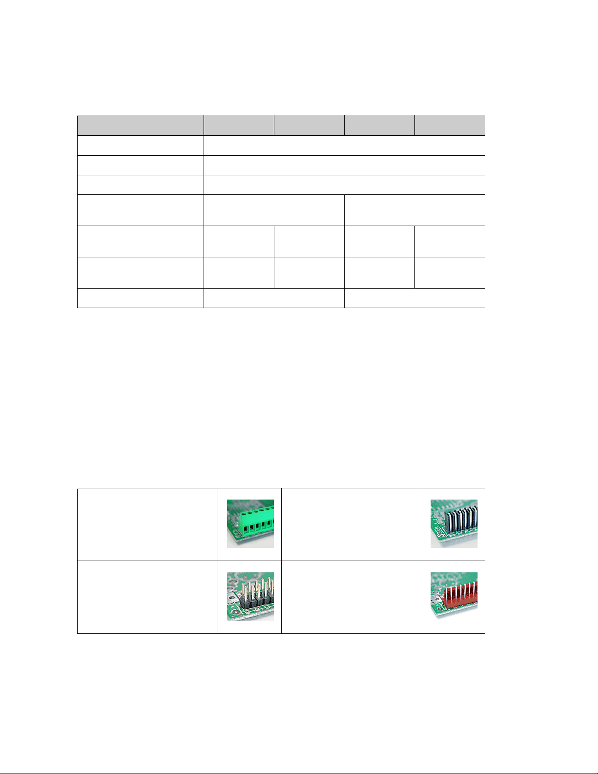
1.2.1 Connector Options
In addition to the standard screw-terminal connectors supplied on BL2100 boards, IDC
headers, bottom-mount sockets, and polarized friction-lock terminals may be factoryinstalled instead. Visit our Web site at www.rabbit.com or contact your Rabbit sales
representative or authorized distributor for further information.
Standard screw terminals, accept
2
up to 14 AWG (1.5 mm
IDC headers, 0.1" pitch
2 Smartcat (BL2100)
) wire
Bottom-mount socket, 0.1" pitch
Polarized friction-lock terminals,
0.1" pitch
Page 9
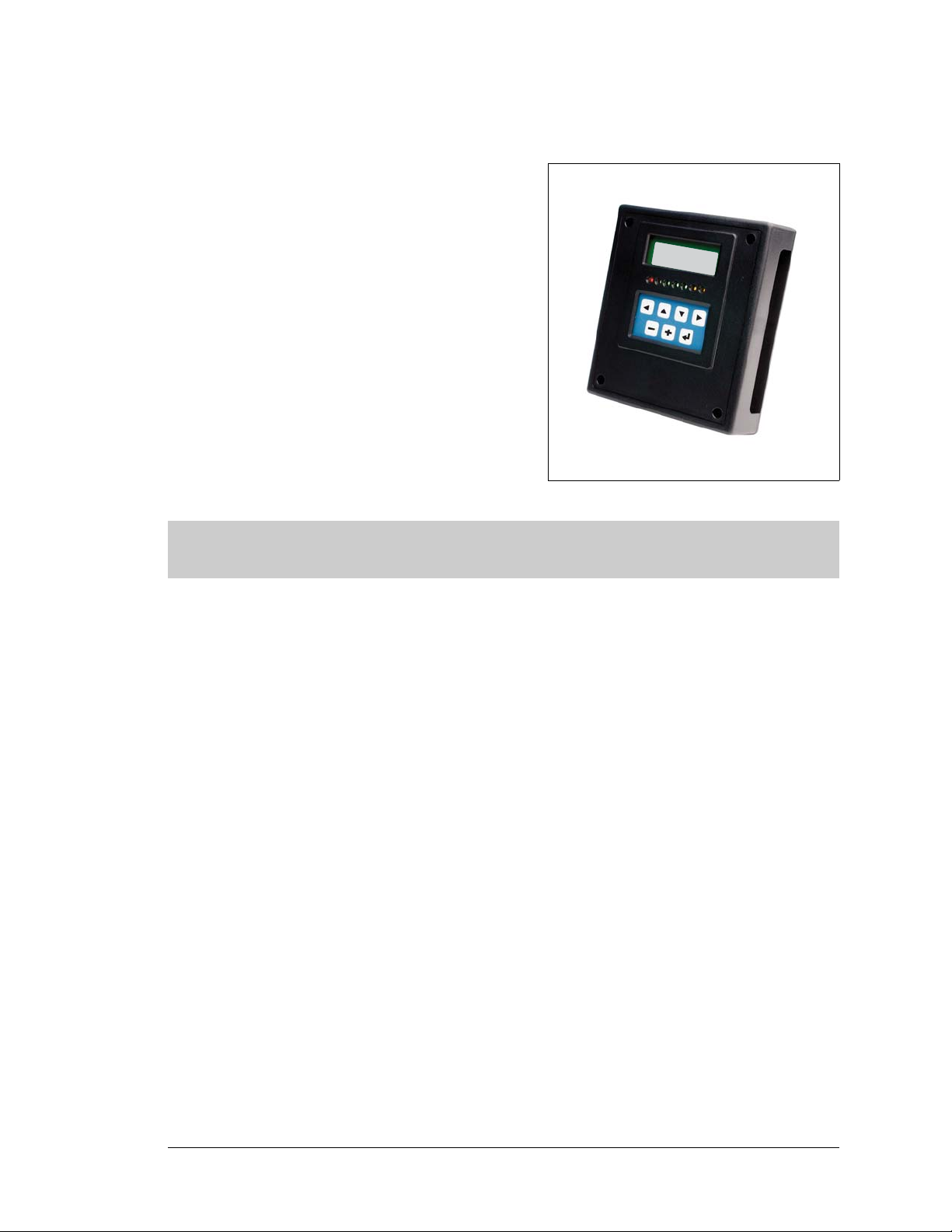
1.3 Optional Add-Ons
• Plastic enclosure (can be wall-mounted or
panel-mounted) with LCD/keypad module that
comprises a 122 × 32 LCD graphic display, 7key keypad, and seven LEDs. The plastic
enclosure consists of a base and a cover for an
assembly made up of the BL2100 with the
LCD/keypad module plugged in.
• Plastic enclosure base.
• LCD/keypad module.
One enclosure base is included with the Tool Kit.
Further details on these add-ons are provided in
Appendix C and in Appendix D.
Visit our Web site for up-to-date information about additional add-ons and features as
they become available. The Web site also has the latest revision of this user’s manual.
User’s Manual 3
Page 10
1.4 Development and Evaluation Tools
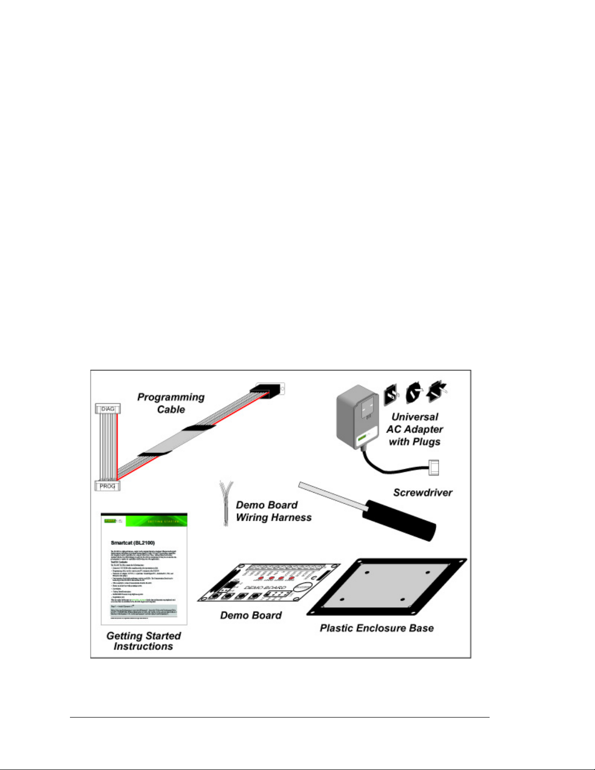
1.4.1 Tool Kit
A T ool Kit contains the hardware essentials you will need to use your own BL2100 singleboard computer. The items in the Tool Kit and their use are as follows.
• BL2100 Getting Started instructions.
• Dynamic C CD-ROM, with complete product documentation on disk.
• Programming cable, used to connect your PC serial port to the BL2100.
• Universal AC adapter, 12 V DC, 1 A (includes Canada/Japan/U.S., Australia/N.Z., U.K.,
and European style plugs).
• Demonstration Board with pushbutton switches and LEDs. The Demonstration Board
can be hooked up to the BL2100 to demonstrate the I/O.
• Wire assembly to connect Demonstration Board to BL2100.
• Plastic enclosure base with mounting screws.
• Screwdriver.
• Rabbit 2000 Processor Easy Reference poster.
• Registration card.
Figure 1. BL2100 Tool Kit
4 Smartcat (BL2100)
Page 11

1.4.2 Software
The BL2100 is programmed using version 7.06 or later of Rabbit’s Dynamic C. A compatible
version is included on the Tool Kit CD-ROM
. Dynamic C v . 9.60 includes the popular µC/OSII real-time operating system, point-to-point protocol (PPP), FAT file system, RabbitWeb,
and other select libraries that were previously sold as individual Dynamic C modules.
Rabbit also offers for purchase the Rabbit Embedded Security Pack featuring the Secure
Sockets Layer (SSL) and a specific Advanced Encryption Standard (AES) library. In addition to the Web-based technical support included at no extra charge, a one-year telephonebased technical support subscription is also available for purchase. Visit our Web site at
www.rabbit.com for further information and complete documentation, or contact your
Rabbit sales representative or authorized distributor.
1.4.3 Online Documentation
The online documentation is installed along with Dynamic C, and an icon for the documentation menu is placed on the workstation’ s desktop. Double-click this icon to reach the
menu. If the icon is missing, use your browser to find and load default.htm in the docs
folder, found in the Dynamic C installation folder.
The latest versions of all documents are always available for free, unregistered download
from our Web sites as well.
User’s Manual 5
Page 12

1.5 CE Compliance
Equipment is generally divided into two classes.
CLASS A CLASS B
Digital equipment meant for light industrial use Digital equipment meant for home use
Less restrictive emissions requirement:
less than 40 dB µV/m at 10 m
(40 dB relative to 1 µV/m) or 300 µV/m
More restrictive emissions requirement:
30 dB µV/m at 10 m or 100 µV/m
These limits apply over the range of 30–230 MHz. The limits are 7 dB higher for frequencies
above 230 MHz. Although the test range goes to 1 GHz, the emissions from Rabbit-based
systems at frequencies above 300 MHz are generally well below background noise levels.
The BL2100 single-board computer has been tested and was found to
be in conformity with the following applicable immunity and emission
standards. The BL2110, BL2120, and BL2130 single-board computers
are also CE qualified as they are sub-versions of the BL2100 singleboard computer. Boards that are CE-compliant have the CE mark.
Immunity
The BL2100 series of single-board computers meets the following EN55024/1998 immunity standards.
• EN61000-4-3 (Radiated Immunity)
• EN61000-4-4 (EFT)
• EN61000-4-6 (Conducted Immunity)
Additional shielding or filtering may be required for a heavy industrial environment.
Emissions
The BL2100 series of single-board computers meets the following emission standards with
the Rabbit 2000 spectrum spreader turned on and set to the normal mode. The spectrum
spreader is only available with Rev. C or higher of the Rabbit 2000 microprocessor. This
microprocessor is used in all BL2100 series boards that carry the CE mark.
• EN55022:1998 Class A
• FCC Part 15 Class A
NOTE: The BL2100 satisfied the Class A limits but not the Class B limits. Such equip-
ment need not be restricted in its sale, but the following warning must be included in
the instructions for its use.
Warning
This is a Class A product. In a domestic environment this product may cause radio
interference, in which case the user may be required to take adequate measures.
Additional shielding or filtering may be needed to meet Class B emissions standards.
6 Smartcat (BL2100)
Page 13

1.5.1 Design Guidelines
Note the following requirements for incorporating a BL2100 series single-board computer
into your application to comply with CE requirements.
General
• The power supply provided with the T ool Kit is for development purposes only. It is the
customer’s responsibility to provide a CE-compliant power supply for the end-product
application.
• When connecting the BL2100 single-board computer to outdoor cables, the customer is
responsible for providing CE-approved surge/lighting protection.
• Rabbit recommends placing digital I/O or analog cables that are 3 m or longer in a
metal conduit to assist in maintaining CE compliance and to conform to good cable
design practices.
• When installing or servicing the BL2100, it is the responsibility of the end-user to use
proper ESD precautions to prevent ESD damage to the BL2100.
Safety
• All inputs and outputs to and from the BL2100 single-board computer must not be con-
nected to voltages exceeding SELV levels (42.4 V AC peak, or 60 V DC).
• The lithium backup battery circuit on the BL2100 single-board computer has been
designed to protect the battery from hazardous conditions such as reverse charging and
excessive current flows. Do not disable the safety features of the design.
1.5.2 Interfacing the BL2100 to Other Devices
There are two versions of the LCD/keypad module that may be used with the BL2100: a
plug-in version (Part No. 101-0465), and a remote panel-mounted version with bezel (Part
No. 101-0502). The BL2100 with the LCD/keypad module plugged in may be regarded as
a “maintenance unit” that conforms to the same CE standards as does the BL2100 alone,
where the entire assembly is mounted inside an enclosure, and the enclosure is only
opened to “tune up” the system. In addition, the cable for a panel-mounted LCD/keypad
module should be less than 30 cm (12") to maintain CE compliance. Appendix C provides
complete information for mounting and using the LCD/keypad module.
Since the BL2100 single-board computers are designed to be connected to other devices,
good EMC practices should be followed to ensure compliance. CE compliance is ultimately the responsibility of the integrator. Additional information, tips, and technical
assistance are available from your authorized Rabbit distributor, and are also available on
our Web site at www.rabbit.com.
User’s Manual 7
Page 14

8 Smartcat (BL2100)
Page 15
2. GETTING STARTED
TVS1
L1
D1
C5
D3
C8
C9
R160
C101
RP9
U16 U17
R151
C95
R158
R159
C100
C25
C21
C22
R187
R134
TP4
R135
C86
U13
BT1
C48
C52
C46
C44
C43
C13
RP4
RP3
RP15
RP14
C87
C89
R140
U12
R133
C85
R132
C88
R139
C51
C50
C49
C24
C92
C90
R148R143
C93
C94
C98
C99
C103
C104
R174
C111 R172
C106
R165
R161
R156
R154
R149
R147
C102
C97
C96
R152
C91
U18
DI08 DI09 DI10 DI11 DI12 DI13 DI14 DI15 RS485 RS485 PE5-INT GND DIO23 DIO22 DIO21 DIO20 DIO19 DIO18 DIO17 DIO16 DIO15 DIO14 DIO13 DIO12 DIO11 DIO10
Q26
D14
C74
R103
R99
C72
Q55
Q43
Q47
Q51
R95
R138
JP1
U7
R82
C61
Q30
Q34
R90
R136
R106
R81
C17
R96
Q52
Q48
J17
D18
C82
RP7
Q44
Q56
C75
D15
Q71
R104
R100
C69
Q67
Q63
Q59
Q4
Q5
RP5
RP6
U4
C14
J16
R11
R9
R10
R119
R186
R142
R8
R7
JP6
J14
Q78
J22
J20
J4
D6
Q23
RP11
C58
R78
Q11
R74
Q15
C54
Q19
R70
C15
U5 U10
C118
Q21
Q17
R72
C56
Q32
Q36
R84
C63
R88
R92
Q28
Q40
C67
D11
C60
D8
Q25
Q13
R80
R76
D9
C65
R86
Q38
U20
C113
C110
C27
R175
C114
R179
R178
R177
C115
R180
R173
C112
R181
Q74
Q75
R176
C12
C6
C7
C11
U1
J21
U2
J7
+K2 +K1 DO09 DO08 DO07 DO06 DO05 DO04 DO03 DO02 DO01 DO00 GND +RAW 232CR 232CT 232DR 232DT DIO0 DIO1 DIO2 DIO3 DIO4 DIO5 DIO6 DIO7
ADCIN10 ADCIN9 ADCIN8 ADCIN7 ADCIN6 ADCIN5 DAC03 DAC02 AGND DAC01 DAC02 ADCIN4 ADCIN3 ADCIN2 ADCIN1 ADCIN0
J1
J11
R162
R155
R153
R145
R146
C26
Battery
J1
R2
C3
D2
R7
C27
R8
R36
RT1
R41
R37
R38
D1
R39
Y2
C2
C1
U8
U7
U3
U6
C7
GND
GND
EGND
DS2
LNK
ACT
DS1
R19
Q3
Q4
Q5
Q2
R1
Y1
C4
C17
C8
R9
R13
R11
U1
BT1
R15
C12
R17
R20
C13
Y3
R16
R22
R21
C14
R18
C25
C28
D3
J2
JP4
JP3
JP1
JP6
C30
JP2
JP5
C29
U2
Flash
EPROM
RCM2200/RCM2300 Module
BL2100 Main Board
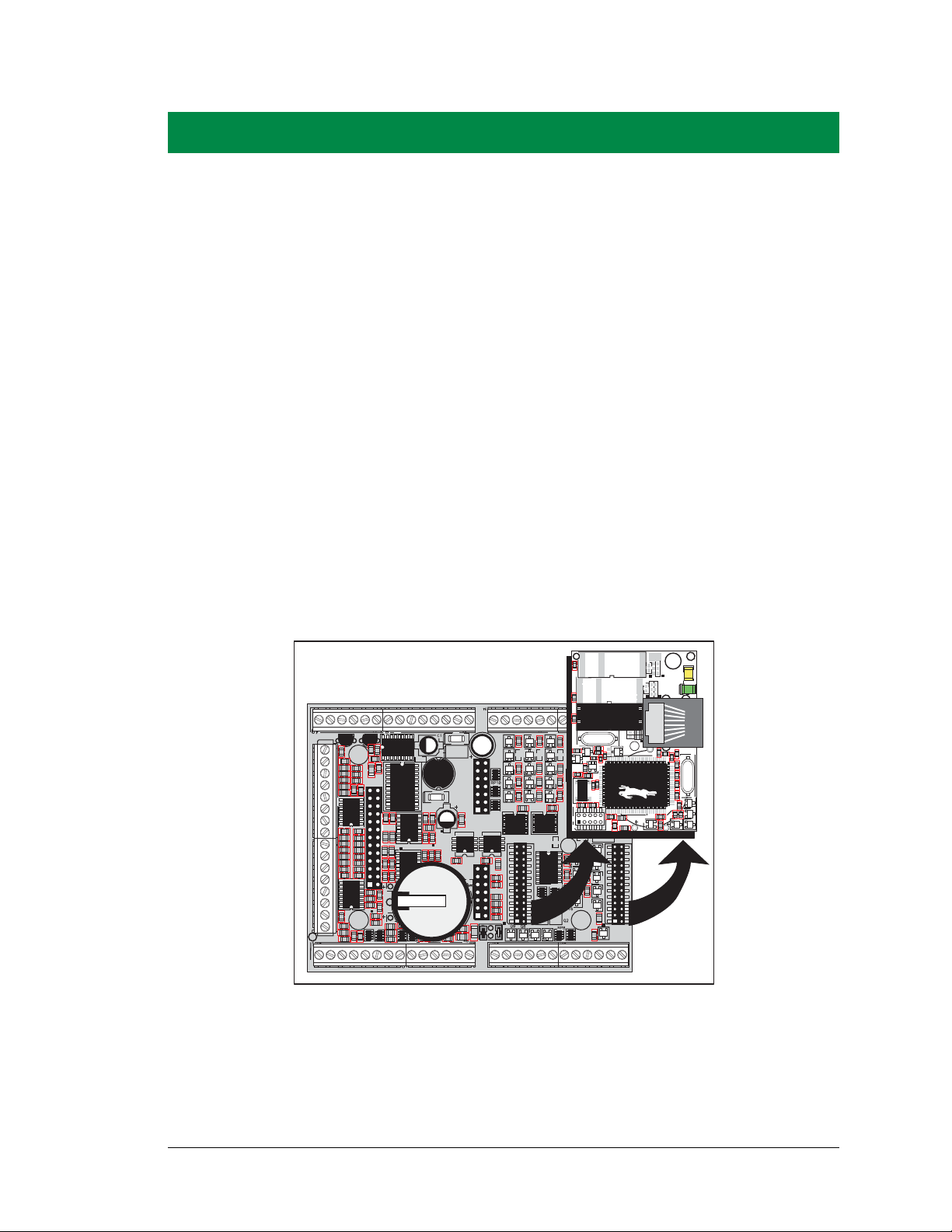
Chapter 2 explains how to connect the programming cable and
power supply to the BL2100.
2.1 BL2100 Connections
1. Remove the RabbitCore module from the BL2100 main board, and set the module
aside. The module is removed to allow access to the mounting holes on the main
BL2100 board, and will be plugged back in to the main board later.
NOTE: If you are working with more than one BL2100 at a time, take care to keep the
BL2100 main boards and their corresponding RabbitCore modules paired since the RabbitCore modules store calibration constants specific to the BL2100 main board to which they
are plugged in.
User’s Manual 9
Figure 2. Remove RabbitCore Module
from BL2100 Main Board
Page 16
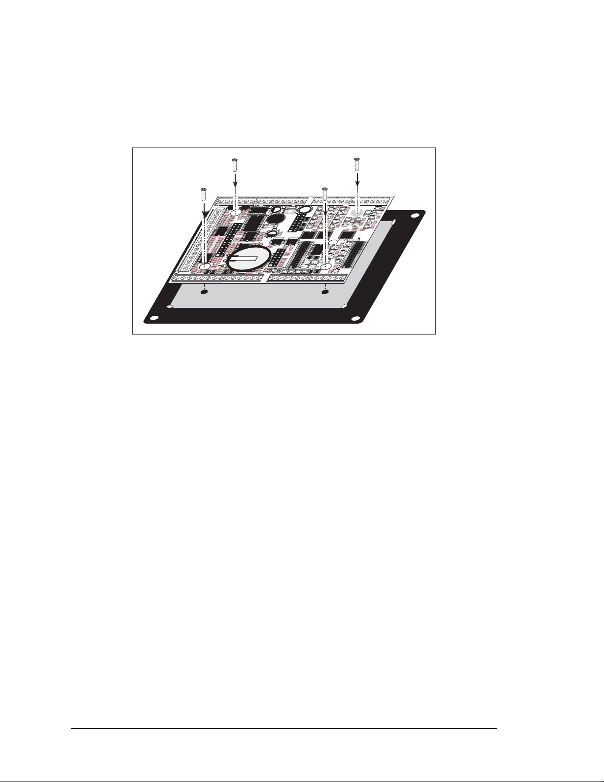
2. Attach the BL2100 main board to the plastic enclosure base.
TVS1
L1
D1
C5
D3
C8
C9
R160C101
RP9
U16 U17
R
151
C95
R
158
R159
C100
C25
C21
C22
R187
R134
TP4
R
135
C86
U13
BT1
C48
C52
C46
C44
C43
C13
RP4
RP3
RP15
RP14
C87
C89
R140
U12
R133
C
85
R
132
C88
R139
C51
C50
C49
C24
C92
C90
R148R143
C93
C94
C98
C99
C103
C104
R174
C111 R172
C106
R165
R161
R156
R154
R149
R147
C
102
C
97
C96
R
152
C91
U18
DI08 DI09 DI10 DI11 DI12 DI13 DI14 DI15 RS485 RS485 PE5-INT GND DIO23 DIO22 DIO21 DIO20 DIO19 DIO18 DIO17 DIO16 DIO15 DIO14 DIO13 DIO12 DIO11 DIO10
Q26
D
14
C
74
R
103
R
99
C72
Q
55
Q
43
Q
47
Q
51
R
95
R138
JP1
U7
R82
C61
Q
30
Q
34
R90
R136
R106
R81
C17
R
96
Q52
Q48
J17
D18
C82
RP7
Q44
Q
56
C
75
D
15
Q
71
R
104
R
100
C
69
Q
67 Q63
Q59
Q4
Q5
RP5
RP6
U4
C14
J16
R11
R9
R
10
R119
R
186
R
142
R8
R7
JP6
J14
Q
78
J22
J20
J4
D
6
Q
23
RP11
C58
R
78
Q
11
R74
Q
15
C54
Q19
R70
C15
U5 U10
C118
Q
21Q
17
R
72
C
56
Q
32
Q
36
R84
C
63
R88
R
92
Q
28
Q
40
C67
D11
C60
D
8
Q
25
Q
13
R80
R76
D9
C65
R86
Q38
U
20
C113
C110
C27
R175
C114
R179
R
178
R177
C115
R180
R173
C112
R
181
Q74
Q75
R176
C
12
C6
C7
C
11
U1
J21
U2
J7
+K2 +K1 DO09 DO08 DO07 DO06 DO05 DO04 DO03 DO02 DO01 DO00 GND +RAW 232CR 232CT 232DR 232DT DIO0 DIO1 DIO2 DIO3 DIO4 DIO5 DIO6 DIO7
ADCIN10 ADCIN9 ADCIN8 AD
CIN7 AD
CIN6 ADCIN5
DAC
03 DAC02 AG
ND DAC01
DAC
02
ADCIN4 ADCIN3 ADCIN2 ADCIN1 ADCIN
0
J1
J11
R
162
R
155
R153
R
145 R
146
C26
Battery
Position the BL2100 main board over the plastic enclosure base as shown below in
Figure 3. Attach the BL2100 to the base using the four 4-40 × ¼ screws supplied with the
enclosure base.
Figure 3. Attach BL2100 Main Board to Plastic Enclosure Base
The plastic enclosure base facilitates handling the BL2100 during development, and provides an attractive mounting alternative. Alternatively, you may wish to use standoffs to
protect the components on the other side of the board. The plastic enclosure base is offered
as a separate option when individual BL2100 boards are purchased.
NOTE: Appendix D, “Plastic Enclosure,” provides additional information and specifications
for the plastic enclosure.
10 Smartcat (BL2100)
Page 17
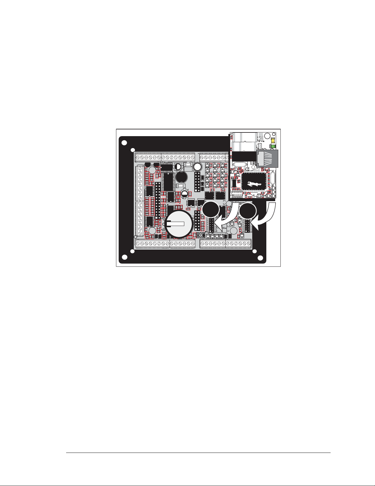
3. Reconnect the RabbitCore module to headers J16 and J17 on the BL2100 main board it
TVS1
L1
D1
C5
D3
C8
C9
R160
C101
RP9
U16 U17
R151
C95
R158
R159
C100
C25
C21
C22
R187
R134
TP4
R135
C86
U13
BT1
C48
C52
C46
C44
C43
C13
RP4
RP3
RP15
RP14
C87
C89
R140
U12
R133
C85
R132
C88
R139
C51
C50
C49
C24
C92
C90
R148R143
C93
C94
C98
C99
C103
C104
R174
C111 R172
C106
R165
R161
R156
R154
R149
R147
C102
C97
C96
R152
C91
U18
DI08 DI09 DI10 DI11 DI12 DI13 DI14 DI15 RS485 RS485 PE5-INT GND DIO23 DIO22 DIO21 DIO20 DIO19 DIO18 DIO17 DIO16 DIO15 DIO14 DIO13 DIO12 DIO11 DIO10
Q26
D14
C74
R103
R99
C72
Q55
Q43
Q47
Q51
R95
R138
JP1
U7
R82
C61
Q30
Q34
R90
R136
R106
R81
C17
R96
Q52
Q48
J17
D18
C82
RP7
Q44
Q56
C75
D15
Q71
R104
R100
C69
Q67
Q63
Q59
Q4
Q5
RP5
RP6
U4
C14
J16
R11
R9
R10
R119
R186
R142
R8
R7
JP6
J14
Q78
J22
J20
J4
D6
Q23
RP11
C58
R78
Q11
R74
Q15
C54
Q19
R70
C15
U5 U10
C118
Q21
Q17
R72
C56
Q32
Q36
R84
C63
R88
R92
Q28
Q40
C67
D11
C60
D8
Q25
Q13
R80
R76
D9
C65
R86
Q38
U20
C113
C110
C27
R175
C114
R179
R178
R177
C115
R180
R173
C112
R181
Q74
Q75
R176
C12
C6
C7
C11
U1
J21
U2
J7
+K2 +K1 DO09 DO08 DO07 DO06 DO05 DO04 DO03 DO02 DO01 DO00 GND +RAW 232CR 232CT 232DR 232DT DIO0 DIO1 DIO2 DIO3 DIO4 DIO5 DIO6 DIO7
ADCIN10 ADCIN9 ADCIN8 ADCIN7 ADCIN6 ADCIN5 DAC03 DAC02 AGND DAC01 DAC02 ADCIN4 ADCIN3 ADCIN2 ADCIN1 ADCIN0
J1
J11
R162
R155
R153
R145
R146
C26
Battery
J1
R2
C3
D2
R7
C27
R8
R36
RT1
R41
R37
R38
D1
R39
Y2
C2
C1
U8
U7
U3
U6
C7
GND
GND
EGND
DS2
LNK
ACT
DS1
R19
Q3
Q4
Q5
Q2
R1
Y1
C4
C17
C8
R9
R13
R11
U1
BT1
R15
C12
R17
R20
C13
Y3
R16
R22
R21
C14
R18
C25
C28
D3
J2
JP4
JP3
JP1
JP6
C30
JP2
JP5
C29
U2
Flash
EPROM
J16
J17
was removed from earlier as shown in Figure 4. Be careful to align the pins over the
headers, and do not bend them as you press down to mate the module with the BL2100
main board.
NOTE: If you are working with more than one BL2100 at a time, take care to keep the
BL2100 main boards and their corresponding RabbitCore modules paired since the RabbitCore modules store calibration constants specific to the BL2100 main board to which they
are plugged in.
User’s Manual 11
Figure 4. Reconnect RabbitCore Module
to BL2100 Main Board
Page 18
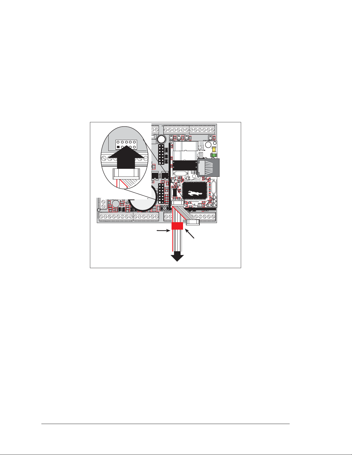
4. Connect the programming cable to download programs from your PC and to program
TVS1
L1
D1
C5
D3
C8
C9
R160
C101
RP9
U16 U17
R151
C95
R158
R159
C100
C25
C21
C22
R187
R134
TP4
R135
C86
U13
BT1
C48
C52
C46
C44
C43
C13
RP4
RP3
RP15
RP14
C87
C89
R140
U12
R133
C85
R132
C88
R139
C51
C50
C49
C24
C92
C90
R148R143
C93
C94
C98
C99
C103
C104
R174
C111 R172
C106
R165
R161
R156
R154
R149
R147
C102
C97
C96
R152
C91
U18
DI08 DI09 DI10 DI11 DI12 DI13 DI14 DI15 RS485 RS485 PE5-INT GND DIO23 DIO22 DIO21 DIO20 DIO19 DIO18 DIO17 DIO16 DIO15 DIO14 DIO13 DIO12 DIO11 DIO10
Q26
D14
C74
R103
R99
C72
Q55
Q43
Q47
Q51
R95
R138
JP1
U7
R82
C61
Q30
Q34
R90
R136
R106
R81
C17
R96
Q52
Q48
J17
D18
C82
RP7
Q44
Q56
C75
D15
Q71
R104
R100
C69
Q67 Q63
Q59
Q4
Q5
RP5
RP6
U4
C14
J16
R11
R9
R10
R119
R186
R142
R8
R7
JP6
J14
Q78
J22
J20
J4
D6
Q23
RP11
C58
R78
Q11
R74
Q15
C54
Q19
R70
C15
U5 U10
C118
Q21
Q17
R72
C56
Q32
Q36
R84
C63
R88
R92
Q28
Q40
C67
D11
C60
D8
Q25
Q13
R80
R76
D9
C65
R86
Q38
U20
C113
C110
C27
R175
C114
R179
R178
R177
C115
R180
R173
C112
R181
Q74
Q75
R176
C12
C6
C7
C11
U1
J21
U2
J7
+K2 +K1 DO09 DO08 DO07 DO06 DO05 DO04 DO03 DO02 DO01 DO00 GND +RAW 232CR 232CT 232DR 232DT DIO0 DIO1 DIO2 DIO3 DIO4 DIO5 DIO6 DIO7
ADCIN10 ADCIN9 ADCIN8 ADCIN7 ADCIN6 ADCIN5 DAC03 DAC02 AGND DAC01 DAC02 ADCIN4 ADCIN3 ADCIN2 ADCIN1 ADCIN0
J1
J11
R162
R155
R153
R145
R146
C26
Battery
J1
R2
C3
D2
R7
C27
R8
R36
RT1
R41
R37
R38
D1
R39
Y2
C2
C1
U8
U7
U3
U6
C7
GND
GND
EGND
DS2
LNK
ACT
DS1
R19
Q3
Q4
Q5
Q2
R1
Y1
C4
C17
C8
R9
R13
R11
U1
BT1
R15
C12
R17
R20
C13
Y3
R16
R22
R21
C14
R18
C25
C28
D3
J2
JP4
JP3
JP1
JP6
C30
JP2
JP5
C29
U2
Flash
EPROM
PROG
J1
Colored edge
To
PC COM port
Programming Cable
DIAG
PROG
Red
shrink wrap
and debug the BL2100.
Connect the 10-pin PROG connector of the programming cable to header J1 on the BL2100
RabbitCore module. Ensure that the colored edge lines up with pin 1 as shown. (Do not use
DIAG connector, which is used for a nonprogramming serial connection.) Connect the
the
other end of the programming cable to a COM port on your PC. Make a note of the port to
which you connect the cable, as Dynamic C will need to have this parameter configured.
Note that COM1 on the PC is the default COM port used by Dynamic C.
Figure 5. Programming Cable Connections
NOTE: Never disconnect the programming cable by pulling on the ribbon cable. Carefully
pull on the connector to remove it from the header.
NOTE: Some PCs now come equipped only with a USB port. It may be possible to use an
12 Smartcat (BL2100)
RS-232/USB converter with the programming cable supplied with the Tool Kit. An RS232/USB converter (part number 20-151-0178) is available through the Web store. Note that
not all RS-232/USB converters work with Dynamic C.
Page 19
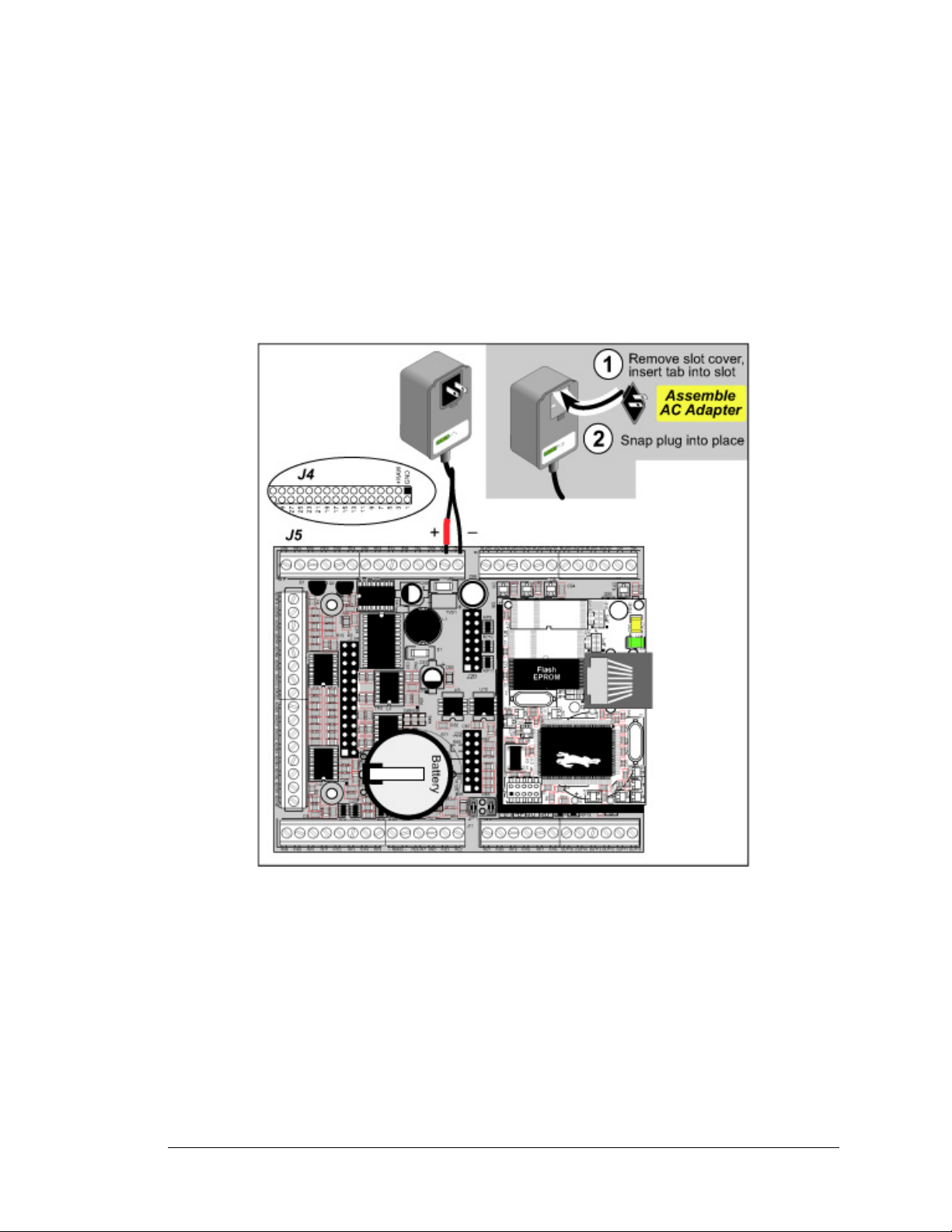
5. Connect the power supply.
First, prepare the AC adapter for the country where it will be used by selecting the plug.
The BL2100 Tool Kit presently includes Canada/Japan/U.S., Australia/N.Z., U.K., and
European style plugs. Snap in the top of the plug assembly into the slot at the top of the
AC adapter as shown in Figure 5, then press down on the spring-loaded clip below the
plug assembly to allow the plug assembly to click into place.
Connect the bare ends of the power supply to the +RAW and GND positions on screwterminal header J5 (IDC header J4) as shown in Figure 6.
Figure 6. Power Supply Connections
6. Apply power.
Plug in the AC adapter. If you are using your own power supply, it must provide 9 to
36 V DC (13 to 36 V DC if you intend to use the full range of the D/A converter
outputs)—voltages outside this range could damage the BL2100.
CAUTION: Unplug the power supply while you make or otherwise work with the connections
to the headers. This will protect your BL2100 from inadvertent shorts or power spikes.
NOTE: A hardware RESET is done by unplugging the AC adapter, then plugging it back in.
User’s Manual 13
Page 20

2.2 Installing Dynamic C
If you have not yet installed Dynamic C version 7.06 (or a later version), do so now by
inserting the Dynamic C CD in your PC’ s CD-ROM drive. The CD will auto-install unless
you have disabled auto-install on your PC.
If the CD does not auto-install, click Start > Run from the Windows Start button and
browse for the Dynamic C setup.exe file on your CD drive. Click OK to begin the
installation once you have selected the setup.exe file.
The installation program will guide you through the installation process. Most steps of the
process are self-explanatory.
Dynamic C uses a COM (serial) port to communicate with the target development system.
The installation allows you to choose the COM port that will be used. The default selection is COM1. You may select any available port for Dynamic C’s use. If you are not certain which port is available, select COM1. This selection can be changed later within
Dynamic C.
Once your installation is complete, you will have up to three icons on your PC desktop.
One icon is for Dynamic C, one opens the documentation menu, and the third is for the
Rabbit Field Utility, a tool used to download precompiled software to a target system.
If you have purchased the optional Dynamic C Rabbit Embedded Security Pack, install it
after installing Dynamic C. You must install the Rabbit Embedded Security Pack in the
same directory where Dynamic C was installed.
The Dynamic C User’s Manual provides detailed instructions for the installation of
Dynamic C and any future upgrades.
NOTE: If you have an earlier version of Dynamic C already installed, the default installation
of the later version will be in a different folder, and a separate icon will appear on your desktop.
14 Smartcat (BL2100)
Page 21

2.3 Starting Dynamic C
Once the BL2100 is connected to your PC and to a power source, start Dynamic C by double-
clicking on the Dynamic C
icon on your desktop or in your Start menu.
If you are using a USB port to connect your computer to the BL2100, choose Options >
Project Options
and select “Use USB to Serial Converter” under the Communications
tab. Click OK.
2.4 Run a Sample Program
Use the File menu to open the sample program PONG.C, which is in the Dynamic C
SAMPLES folder. Press function key F9 to compile and run the program. The STDIO
window will open on your PC and will display a small square bouncing around in a box.
This program shows that the CPU is working. The sample program described in
Section 5.2.3, “Run the PINGME.C Demo,” tests the TCP/IP portion of the board.
2.4.1 Troubleshooting
If Dynamic C cannot find the target system (error message "No Rabbit Processor
Detected."
• Check that the BL2100 is powered correctly — the AC adapter should be plugged in to the
+RAW and GND positions on screw-terminal header J5 (IDC header J4).
):
• Check both ends of the programming cable to ensure that they are firmly plugged into
the PC and the PROG connector, not the DIAG connector, is plugged in to the programming port on the RabbitCore module with the marked (colored) edge of the programming cable towards pin 1 of the programming header.
• Ensure that the RabbitCore module is firmly and correctly installed in its connectors on
the BL2100 main board.
• Dynamic C uses the COM port specified during installation. Select a different COM
port within Dynamic C. From the
Communications. Select another COM port from the list, then click OK. Press
<Ctrl-Y> to force Dynamic C to recompile the BIOS. If Dynamic C still reports it is
Options menu, select Project Options, then select
unable to locate the target system, repeat the above steps until you locate the COM port
used by the programming cable.
If Dynamic C appears to compile the BIOS successfully, but you then receive a communication error message when you compile and load a sample program, it is possible that your
PC cannot handle the higher program-loading baud rate. Try changing the maximum
download rate to a slower baud rate as follows.
• Locate the
Serial Options dialog in the Dynamic C Options > Communications
menu. Select a slower Max download baud rate.
User’s Manual 15
Page 22

If a program compiles and loads, but then loses target communication before you can
begin debugging, it is possible that your PC cannot handle the default debugging baud
rate. Try lowering the debugging baud rate as follows.
• Locate the Serial Options dialog in the Dynamic C Options > Communications
menu. Choose a lower debug baud rate.
2.5 Where Do I Go From Here?
If the sample program ran fine, you are now ready to go on to other sample programs and to
develop your own applications. The source code for the sample programs
you to modify them for your own use. The BL2100 User’s Manual also provides complete
hardware reference information and describes the software function calls for the BL2100 and
the optional LCD/keypad module.
For advanced development topics, refer to the Dynamic C User’s Manual and the
Dynamic C TCP/IP User’s Manual, also in the online documentation set.
2.5.1 Technical Support
NOTE: If you purchased your BL2100 through a distributor or Rabbit partner, contact the
distributor or partner first for technical support.
If there are any problems at this point:
is provided to allow
• Use the Dynamic C Help menu to get further assistance with Dynamic C.
• Check the Rabbit Technical Bulletin Board and forums at www.rabbit.com/support/bb/
and at www.rabbit.com/forums/.
• Use the Technical Support e-mail form at www.rabbit.com/support/.
If the sample program ran fine, you are now ready to go on to explore other BL2100 features and develop your own applications.
Chapter 3, “Subsystems,” provides a description of the BL2100’s features, Chapter 4,
“Software,” describes the Dynamic C software libraries and introduces some sample programs, and Chapter 5, “Using the TCP/IP Features,” explains the TCP/IP features.
16 Smartcat (BL2100)
Page 23
3. SUBSYSTEMS
Ethernet
SRAM
Flash
11 MHz
osc
32 kHz
osc
RabbitCore Module
Decoder
Control
Interface
to
LCD/Keypad
Module
RABBIT
2000
RS-232
RS-485
Data
Register
Data
Register
A/D
Converter
D/A
Converter
Digital
Input
Digital
Output
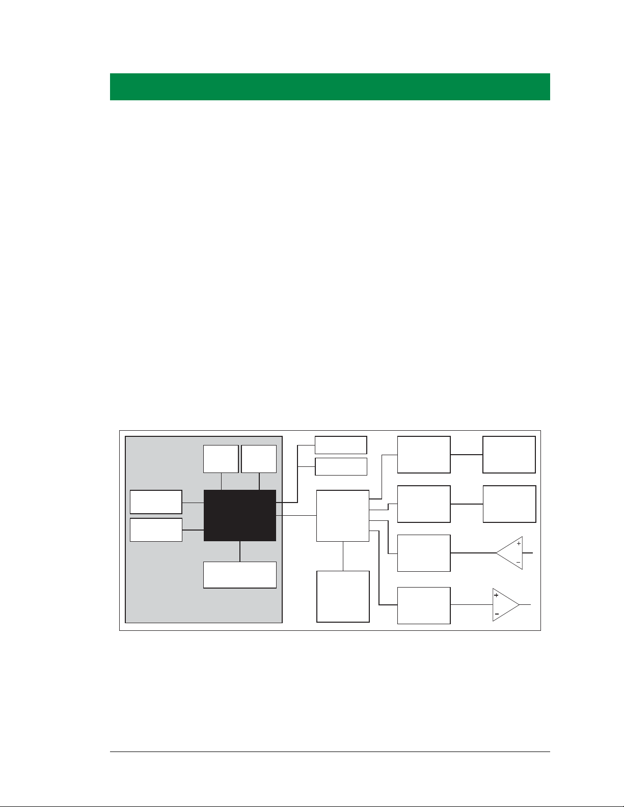
Chapter 3 describes the principal subsystems for the BL2100.
•Digital I/O
•Serial Communication
•A/D Converter Inputs
•D/A Converter Outputs
•Analog Reference Voltage Circuit
•Memory
•External Interrupts
Figure 7 shows these Rabbit-based subsystems designed into the BL2100.
User’s Manual 17
Figure 7. BL2100 Subsystems
Page 24
3.1 BL2100 Pinouts
J2
12
11
10
9
8
7
6
5
4
3
2
1
J10
14
13
12
11
10
9
8
7
6
5
4
3
2
1
J5
1
2
3
4
5
6
7
8
9
10
11
12
13
14
1
2
3
4
5
6
7
8
9
10
11
12
J8
J1
R2
C3
D2
R7
C27
R8
R36
RT1
R41
R37
R38
D1
R39
Y2
C2
C1
U8
U7
U3
U6
C7
GND
GND
EGND
DS2
LNK
ACT
DS1
R19
Q3
Q4
Q5
Q2
R1
Y1
C4
C17
C8
R9
R13
R11
U1
BT1
R15
C12
R17
R20
C13
Y3
R16
R22
R21
C14
R18
C25
C28
D3
J2
JP4
JP3
JP1
JP6
C30
JP2
JP5
C29
U2
Flash
EPROM
J2
J14
Digital
Outputs
Digital
Inputs
RS-232
Power
Supply
K
Digital
Inputs
Digital
Outputs
RS-485
Digital
Inputs
Analog
Inputs
Analog
Inputs
Analog
Ground
Analog
Outputs
16 15 14 13 12 11 10 9 8 7 6 5 4 3 2 1
IN07
IN06
IN05
IN04
IN03
IN02
IN01
IN00
TXB
RXB
TXC/RTS
RXC/CTS
+RAW
GND
OUT00
OUT01
OUT02
OUT03
OUT04
OUT05
OUT06
OUT07
OUT08
OUT09
+K1
+K2
IN08
IN09
IN10
IN11
IN12
IN13
IN14
IN15
RS-485+
RS-485
PE5INT
GND
IN23
IN22
IN21
IN20
IN19
IN18
IN17
IN16
OUT15
OUT14
OUT13
OUT12
OUT11
OUT10
ADC00 ADC01 ADC02 ADC03 ADC04 DAC0 DAC1 AGND DAC2 DAC3 ADC05 ADC06 ADC07 ADC08 ADC09 ADC10
Battery
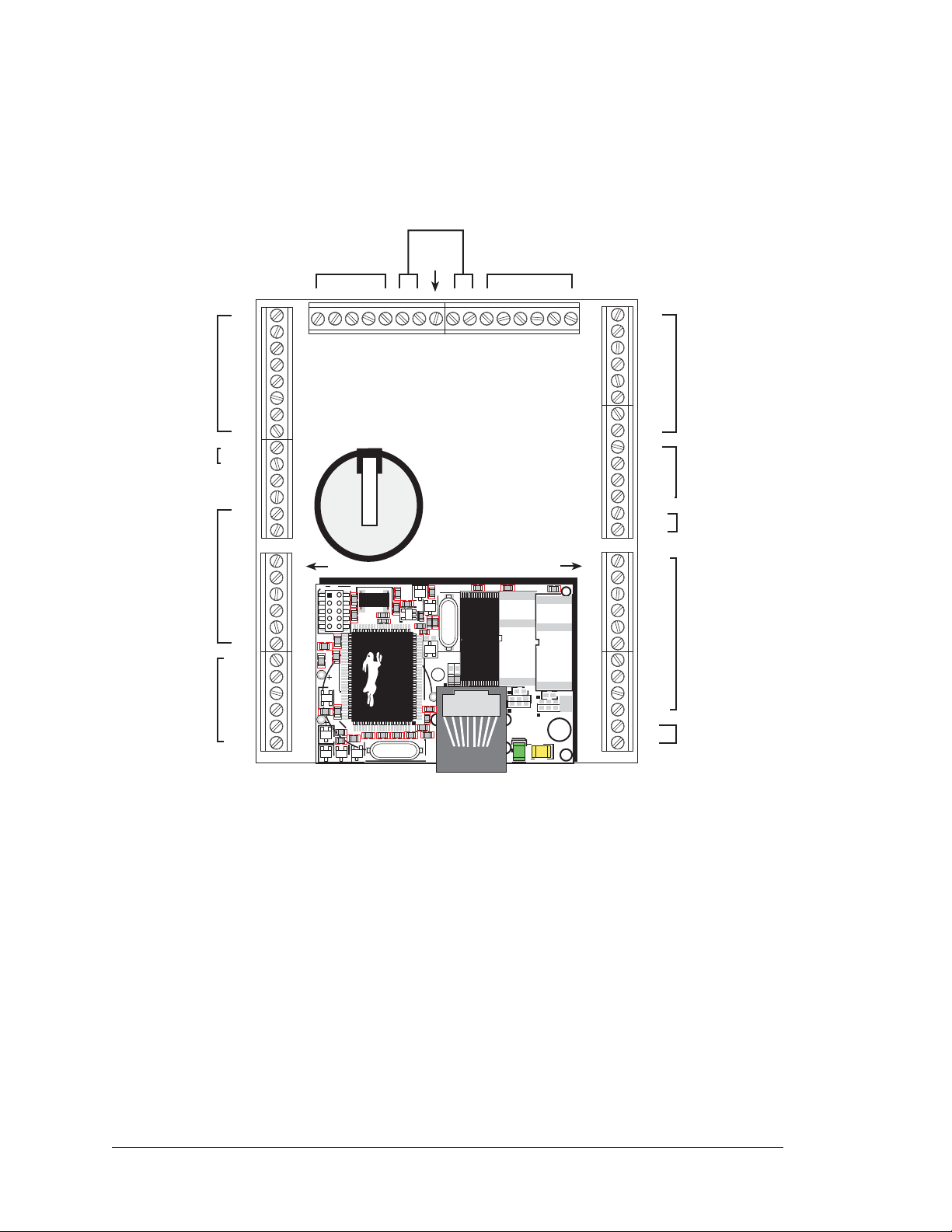
The BL2100 pinouts are shown in Figure 8(a) and Figure 8(b).
NOTE: Screw-terminal header J2 and the associated analog I/O are not available on the
BL2110 and the BL2130.
Figure 8(a). BL2100 Pinouts (screw-terminal headers)
18 Smartcat (BL2100)
Page 25
3.1.1 Headers and Screw Terminals
J2
J10
J4
J7
IN07
IN06
IN05
IN04
IN03
IN02
IN01
IN00
TXB
RXB
TXC/RTS
RXC/CTS
+RAW
GND
OUT00
OUT01
OUT02
OUT03
OUT04
OUT05
OUT06
OUT07
OUT08
OUT09
+K1
+K2
39
37
35
33
31
29
27
25
23
21
19
17
15
13
11
9
7
5
3
1
33
31
29
27
25
23
21
19
17
15
13
11
9
7
5
3
1
IN08
IN09
IN10
IN11
IN12
IN13
IN14
IN15
RS-485+
RS-485
PE5INT
GND
IN23
IN22
1
3
5
7
9
11
13
15
17
19
21
23
25
27
29
31
33
1
3
5
7
9
11
13
15
17
19
21
23
25
27
29
31
33
35
37
39
ADC00
ADC01
ADC02
ADC03
ADC04
DAC0
DAC1
AGND
DAC2
DAC3
ADC05
ADC06
ADC07
ADC08
ADC09
ADC10
49 47 45 43 41 39 37 35 33 31 29 27 25 23 21 19 17 15 13 11 9 7 5 3 1
IN21
IN20
IN19
IN18
IN17
IN16
OUT15
OUT14
OUT13
OUT12
OUT11
OUT10
J1
R2
C3
D2
R7
C27
R8
R36
RT1
R41
R37
R38
D1
R39
Y2
C2
C1
U8
U7
U3
U6
C7
GND
GND
EGND
DS2
LNK
ACT
DS1
R19
Q3
Q4
Q5
Q2
R1
Y1
C4
C17
C8
R9
R13
R11
U1
BT1
R15
C12
R17
R20
C13
Y3
R16
R22
R21
C14
R18
C25
C28
D3
J2
JP4
JP3
JP1
JP6
C30
JP2
JP5
C29
U2
Flash
EPROM
J1
J13
Digital
Outputs
Digital
Inputs
RS-232
Power
Supply
K
Digital
Inputs
Digital
Outputs
RS-485
Digital
Inputs
Analog
Inputs
Analog
Inputs
Analog
Ground
Analog
Outputs
Battery
Standard BL2100 models are equipped with two 1 × 12 screw-terminal strips (J8 and J14),
and two 1 × 14 screw-terminal strips (J5 and J11). The BL2100 and BL2110 also have the
RJ-45 Ethernet jack and one 1 × 16 screw-terminal strip (J2).
There is provision on the circuit board to accommodate one of the following types of
connectors instead of the screw-terminal strips.
• 2 × 17, 2 × 20, and 2 × 25 IDC headers with a pitch of 0.1".
• 1 × 17, 1 × 20, and 1 × 25 friction-lock connectors with a pitch of 0.1". The holes used
by the friction-lock connectors are on the “outside” edges of the connector locations.
• 1 × 17, 1 × 20, and 1 × 25 bottom-mount sockets with a pitch of 0.1". The holes for the
bottom-mount sockets are on the “outside” edges of the connector locations
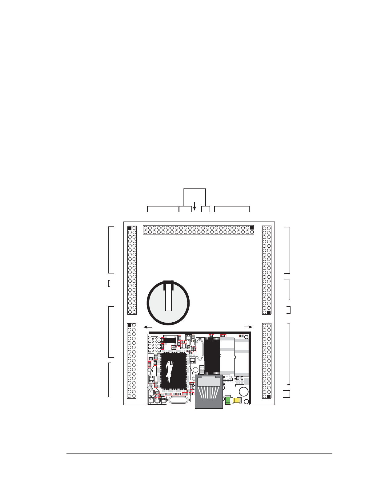
The pinouts for these connectors are shown in Figure 8(b).
User’s Manual 19
NOTE: Header J1 and the associated analog I/O are not available on the BL2110 and the
BL2130.
Figure 8(b). BL2100 Pinouts (other 0.1" connectors)
Page 26
3.2 Digital I/O
1 nF
100 kW
27 kW
Rabbit 2000
Microprocessor
Factory
Default
Vcc
GND
+K2
0 W
+40 V
+36 V
+3.3 V
40 V
Normal Switching
Levels
Spikes
Digital Input Voltage
Spikes
Spikes
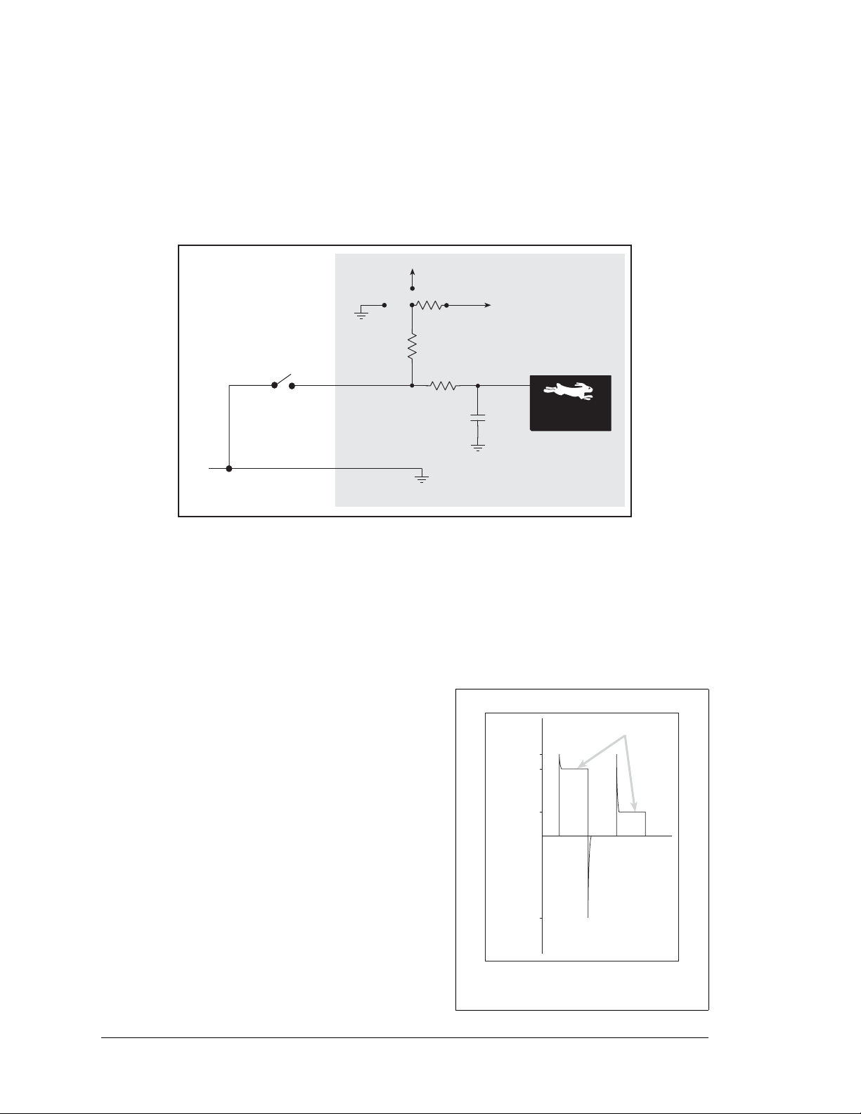
3.2.1 Digital Inputs
The BL2100 has 24 digital inputs, IN00–IN23, each of which is protected over a range of
–36 V to +36 V. The inputs are factory-configured to be pulled up to +5 V, but they can
also be pulled up to +K2 or down to 0 V in banks of eight by changing a surface-mounted
0 resistor as shown in Figure 9.
Figure 9. BL2100 Digital Inputs [Pulled Up—Factory Default]
NOTE: If the inputs are pulled up to +K2, the voltage range over which the digital inputs
are protected changes to K2 – 36 V to +36 V.
The actual switching threshold is approximately 2.40 V. Anything below this value is a
logic 0, and anything above is a logic 1.
The digital inputs are each fully protected over a
range of -36 V to +36 V, and can handle short
spikes of ±40 V.
Figure 10. BL2100 Digital Input
20 Smartcat (BL2100)
Protected Range
Page 27
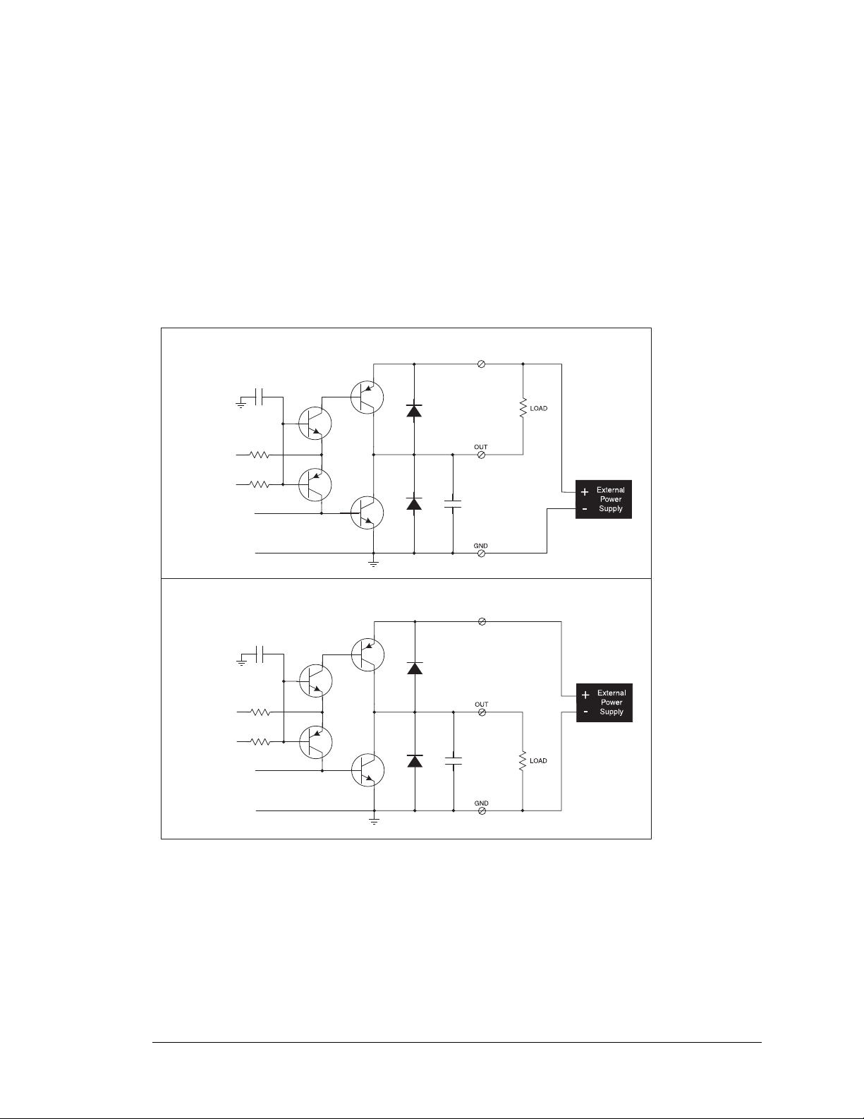
3.2.2 Digital Outputs
K1 or K2
D-REF
DCNTL_[015]
K1 or K2
D-REF
DCNTL_[015]
SINKING OUTPUT
SOURCING OUTPUT
The BL2100 has 16 digital outputs, OUT00–OUT15, which can each sink or source up to
200 mA. Figure 11 shows a wiring diagram for using the digital outputs in a sinking or a
souring configuration.
All the digital outputs sink and source actively. They can be used as high-side drivers,
low-side drivers, or as an H-bridge driver. When the BL2100 is first powered up or reset,
all the outputs are disabled, that is, at a high-impedance status, until the digoutConfig
software function call is made. The digoutConfig call sets the initial state of each digital output according to the configuration specified by the user, and enables the digital outputs to their initial status.
OUT00–OUT07 are powered by to +K1, and OUT08–OUT15 are powered by +K2.
K1 and K2 can each be up to 36 V. They don't have to be same.
All the sinking current, which could be up to 3.2 A, is returned through the GND pins. Be
sure to use a suitably sized GND and keep the distance to the power supply as short as
possible. Since there are two GND terminals (header J5/J4, and header J11/J10), it is
Figure 11. BL2100 Digital Outputs
User’s Manual 21
Page 28
highly recommend that you split the GND returns according to the two banks of digital
+K
+K
LOAD
A
A
B
B
outputs.
For the H bridge, which is shown in Figure 12,
K1 and K2 should be the same if two digital outputs used for the H bridge are on different banks.
Figure 12. H Bridge
22 Smartcat (BL2100)
Page 29

3.3 Serial Communication
The BL2100 has two RS-232 serial ports, which can be configured as one RS-232 serial
channel (with R TS/CTS) or as two RS-232 (3-wire) channels using the serMode software
function call. Table 2 summarizes the options.
Table 2. Serial Communication Configurations
Serial Port
Mode
B C D
0 RS-232, 3-wire RS-232, 3-wire RS-485
1 RS-232, 5-wire CTS/R TS RS-485
The BL2100 also has one RS-485 serial channel and one CMOS serial channel that serves
as the programming port.
All four serial ports operate in an asynchronous mode. An asynchronous port can handle 7
or 8 data bits. A 9th bit address scheme, where an additional bit is sent to mark the first
byte of a message, is also supported. Serial Port A, the programming port, can be operated
alternately in the clocked serial mode. In this mode, a clock line synchronously clocks the
data in or out. Either of the two communicating devices can supply the clock. The BL2100
boards typically use all four ports in the asynchronous serial mode. Serial Ports B and C
are used for RS-232 communication, and Serial Port D is used for RS-485 communication. The BL2100 uses an 11.0592 MHz crystal, which is doubled to 22.1 184 MHz. At this
frequency, the BL2100 supports standard asynchronous baud rates up to a maximum of
230,400 bps.
3.3.1 RS-232
The BL2100 RS-232 serial communication is supported by an RS-232 transceiver. This
transceiver provides the voltage output, slew rate, and input voltage immunity required to
meet the RS-232 serial communication protocol. Basically, the chip translates the Rabbit
2000’ s CMOS/TTL signals to RS-232 signal levels. Note that the polarity is reversed in an
RS-232 circuit so that a +5 V output becomes approximately -10 V and 0 V is output as
+10 V. The RS-232 transceiver also provides the proper line loading for reliable communication.
RS-232 can be used effectively at the BL2100’s maximum baud rate for distances of up to
15 m.
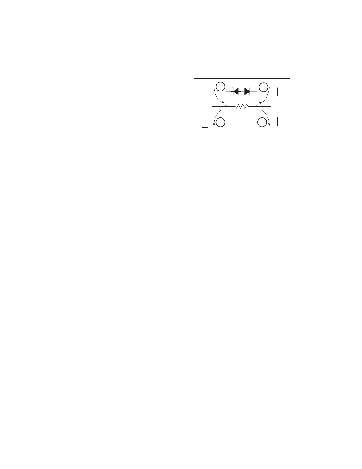
3.3.2 RS-485
The BL2100 has one RS-485 serial channel, which is connected to the Rabbit 2000 Serial
Port D through an RS-485 transceiver. The half-duplex communication uses the Rabbit
2000’s PB6 pin to control the transmit enable on the communication line.
User’s Manual 23
Page 30
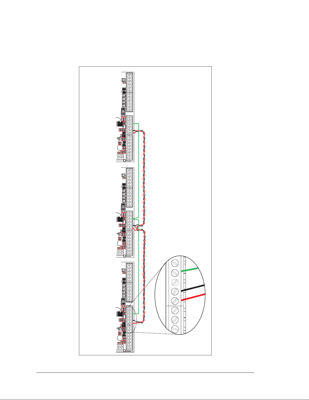
The BL2100 can be used in an RS-485 multidrop network. Connect the 485+ to 485+ and
C48
C52
C46
C44
C43
C13
RP4
RP3
RP15
RP14
C87
C89
R140
R133
C85
R132
C88
R139
C51
C50
C49
DI08 DI09 DI10 DI11 DI12 DI13 DI14 DI15 RS485 RS485 PE5-INT GND DIO23 DIO22 DIO21 DIO20 DIO19 DIO18 DIO17 DIO16 DIO15 DIO14 DIO13 DIO12 DIO11 DIO10
D18
C82
RP7
JP6
J14
ADCIN1 ADCIN0
J11
C48
C52
C46
C44
C43
C13
RP4
RP3
RP15
RP14
C87
C89
R140
R133
C85
R132
C88
R139
C51
C50
C49
DI08 DI09 DI10 DI11 DI12 DI13 DI14 DI15 RS485 RS485 PE5-INT GND DIO23 DIO22 DIO21 DIO20 DIO19 DIO18 DIO17 DIO16 DIO15 DIO14 DIO13 DIO12 DIO11 DIO10
D18
C82
RP7
JP6
J14
ADCIN1 ADCIN0
J11
C48
C52
C46
C44
C43
C13
RP4
RP3
RP15
RP14
C87
C89
R140
R133
C85
R132
C88
R139
C51
C50
C49
DI08 DI09 DI10 DI11 DI12 DI13 DI14 DI15 RS485 RS485 PE5-INT GND DIO23 DIO22 DIO21 DIO20 DIO19 DIO18 DIO17 DIO16 DIO15 DIO14 DIO13 DIO12 DIO11 DIO10
D18
C82
RP7
JP6
J14
ADCIN1 ADCIN0
J11
IN2
GND
PE5-INT
485
485+
IN15
IN14
IN1
J11
12
11
10
9
8
7
Ground recommended
485– to 485– using single twisted-pair wires (nonstranded, tinned) as shown in Figure 13.
Note that a common ground is recommended.
24 Smartcat (BL2100)
Figure 13. BL2100 Multidrop Network
Page 31

The BL2100 comes with a 220 termination resistor and two 681 bias resistors installed
TVS1
L1
D1
C5
D3
C8
C9
R160
C101
RP9
U16 U17
R151
C95
R158
R159
C100
C25
C21
C22
R187
R134
TP4
R135
C86
U13
BT1
C48
C52
C46
C44
C43
C13
RP4
RP3
RP15
RP14
C87
C89
R140
U12
R133
C85
R132
C88
R139
C51
C50
C49
C24
C92
C90
R148R143
C93
C94
C98
C99
C103
C104
R174
C111 R172
C106
R165
R161
R156
R154
R149
R147
C102
C97
C96
R152
C91
U18
DI08 DI09 DI10 DI11 DI12 DI13 DI14 DI15 RS485 RS485 PE5-INT GND DIO23 DIO22 DIO21 DIO20 DIO19 DIO18 DIO17 DIO16 DIO15 DIO14 DIO13 DIO12 DIO11 DIO10
Q26
D14
C74
R103
R99
C72
Q55
Q43
Q47
Q51
R95
R138
JP1
U7
R82
C61
Q30
Q34
R90
R136
R106
R81
C17
R96
Q52
Q48
J17
D18
C82
RP7
Q44
Q56
C75
D15
Q71
R104
R100
C69
Q67 Q63
Q59
Q4
Q5
RP5
RP6
U4
C14
J16
R11
R9
R10
R119
R186
R142
R8
R7
JP6
J14
Q78
J22
J20
J4
D6
Q23
RP11
C58
R78
Q11
R74
Q15
C54
Q19
R70
C15
U5 U10
C118
Q21Q17
R72
C56
Q32
Q36
R84
C63
R88
R92
Q28
Q40
C67
D11
C60
D8
Q25
Q13
R80
R76
D9
C65
R86
Q38
U20
C113
C110
C27
R175
C114
R179
R178
R177
C115
R180
R173
C112
R181
Q74
Q75
R176
C12
C6
C7
C11
U1
J21
U2
J7
+K2 +K1 DO09 DO08 DO07 DO06 DO05 DO04 DO03 DO02 DO01 DO00 GND +RAW 232CR 232CT 232DR 232DT DIO0 DIO1 DIO2 DIO3 DIO4 DIO5 DIO6 DIO7
ADCIN10 ADCIN9 ADCIN8 ADCIN7 ADCIN6 ADCIN5 DAC03 DAC02 AGND DAC01 DAC02 ADCIN4 ADCIN3 ADCIN2 ADCIN1 ADCIN0
J1
J11
R162
R155
R153
R145
R146
C26
Battery
J1
R2
C3
D2
R7
C27
R8
R36
RT1
R41
R37
R38
D1
R39
Y2
C2
C1
U8
U7
U3
U6
C7
GND
GND
EGND
DS2
LNK
ACT
DS1
R19
Q3
Q4
Q5
Q2
R1
Y1
C4
C17
C8
R9
R13
R11
U1
BT1
R15
C12
R17
R20
C13
Y3
R16
R22
R21
C14
R18
C25
C28
D3
J2
JP4
JP3
JP1
JP6
C30
JP2
JP5
C29
U2
Flash
EPROM
JP1
4
3
2
1
R51
681 W
R58
220 W
R53
681 W
485+
485
6
7
termi-
nation
bias
bias
U8
JP1
2
1
6
5
6
5
Factory
Default
and enabled with jumpers across pins 1–2 and 5–6 on header JP1, as shown in Figure 14.
Figure 14. RS-485 Termination and Bias Resistors
For best performance, the bias and termination resistors in a multidrop network should
only be enabled on both end nodes of the network. Disable the termination and bias resistors on any intervening BL2100 units in the network by removing both jumpers from
header JP1.
TIP: Save the jumpers for possible future use by “parking” them across pins 1–3 and 4–6
of header JP1. Pins 3 and 4 are not otherwise connected to the BL2100.
User’s Manual 25
Page 32

3.3.3 Ethernet Port
ETHERNET
RJ-45 Plug
1. E_Tx+
2. E_Tx
3. E_Rx+
6. E_Rx
1
8
RJ-45 Jack
RJ-45 Ethernet Plug
R29
Chassis
Ground
Board
Ground
Figure 15 shows the pinout for the Ethernet port (J2 on the BL2100 module). Note that
there are two standards for numbering the pins on this connector—the convention used
here, and numbering in reverse to that shown. Regardless of the numbering convention
followed, the pin positions relative to the spring tab position (located at the bottom of the
RJ-45 jack in Figure 15) are always absolute, and the RJ-45 connector will work properly
with off-the-shelf Ethernet cables.
Figure 15. RJ-45 Ethernet Port Pinout
RJ-45 pinouts are sometimes numbered opposite to the way shown in Figure 15.
Two LEDs are placed next to the RJ-45 Ethernet jack, one to indicate an Ethernet link
(LNK) and one to indicate Ethernet activity (ACT).
The transformer/connector assembly ground is connected to the BL2100 module printed
circuit board digital ground via a 0 resistor “jumper,” R29, as shown in Figure 16.
Figure 16. Isolation Resistor R29
The factory default is for the 0 resistor “jumper” at R29 to be installed. In high-noise
environments, remove R29 and ground the transformer/connector assembly directly
through the chassis ground. This will be especially helpful to minimize ESD and/or EMI
problems.
26 Smartcat (BL2100)
Page 33

3.3.4 Programming Port
The RabbitCore module on the BL2100 has a 10-pin programming header. The programming port uses the Rabbit 2000’s Serial Port A for communication. Dynamic C uses the
programming port to download and debug programs.
The programming port is also used for the following operations.
• Cold-boot the Rabbit 2000 on the RabbitCore module after a reset.
• Remotely download and debug a program over an Ethernet connection using the
RabbitLink EG2110.
• Fast copy designated portions of flash memory from one Rabbit-based board (the
master) to another (the slave) using the Rabbit Cloning Board.
In addition to Serial Port A, the Rabbit 2000 startup-mode (SMODE0, SMODE1), status,
and reset pins are available on the serial programming port.
The two startup mode pins determine what happens after a reset—the Rabbit 2000 is
either cold-booted or the program begins executing at address 0x0000.
The status pin is used by Dynamic C to determine whether a Rabbit microprocessor is
present. The status output has three different programmable functions:
1. It can be driven low on the first op code fetch cycle.
2. It can be driven low during an interrupt acknowledge cycle.
3. It can also serve as a general-purpose output.
The /RESET_IN pin is an external input that is used to reset the Rabbit 2000 and the
onboard peripheral circuits on the RabbitCore module. The serial programming port can be
used to force a hard reset on the RabbitCore module by asserting the /RESET_IN signal.
Alternate Uses of the Serial Programming Port
All three clocked Serial Port A signals are available as
• a synchronous serial port
• an asynchronous serial port, with the clock line usable as a general CMOS input
The programming port may also be used as a serial port once the application is running.
The SMODE pins may then be used as inputs and the status pin may be used as an output.
Refer to the Rabbit 2000 Microprocessor User’s Manual for more information.
User’s Manual 27
Page 34

3.4 Programming Cable
TVS1
L1
D1
C5
D3
C8
C9
R160
C101
RP9
U16 U17
R151
C95
R158
R159
C100
C25
C21
C22
R187
R134
TP4
R135
C86
U13
BT1
C48
C52
C46
C44
C43
C13
RP4
RP3
RP15
RP14
C87
C89
R140
U12
R133
C85
R132
C88
R139
C51
C50
C49
C24
C92
C90
R148R143
C93
C94
C98
C99
C103
C104
R174
C111 R172
C106
R165
R161
R156
R154
R149
R147
C102
C97
C96
R152
C91
U18
DI08 DI09 DI10 DI11 DI12 DI13 DI14 DI15 RS485 RS485 PE5-INT GND DIO23 DIO22 DIO21 DIO20 DIO19 DIO18 DIO17 DIO16 DIO15 DIO14 DIO13 DIO12 DIO11 DIO10
Q26
D14
C74
R103
R99
C72
Q55
Q43
Q47
Q51
R95
R138
JP1
U7
R82
C61
Q30
Q34
R90
R136
R106
R81
C17
R96
Q52
Q48
J17
D18
C82
RP7
Q44
Q56
C75
D15
Q71
R104
R100
C69
Q67 Q63
Q59
Q4
Q5
RP5
RP6
U4
C14
J16
R11
R9
R10
R119
R186
R142
R8
R7
JP6
J14
Q78
J22
J20
J4
D6
Q23
RP11
C58
R78
Q11
R74
Q15
C54
Q19
R70
C15
U5 U10
C118
Q21
Q17
R72
C56
Q32
Q36
R84
C63
R88
R92
Q28
Q40
C67
D11
C60
D8
Q25
Q13
R80
R76
D9
C65
R86
Q38
U20
C113
C110
C27
R175
C114
R179
R178
R177
C115
R180
R173
C112
R181
Q74
Q75
R176
C12
C6
C7
C11
U1
J21
U2
J7
+K2 +K1 DO09 DO08 DO07 DO06 DO05 DO04 DO03 DO02 DO01 DO00 GND +RAW 232CR 232CT 232DR 232DT DIO0 DIO1 DIO2 DIO3 DIO4 DIO5 DIO6 DIO7
ADCIN10 ADCIN9 ADCIN8 ADCIN7 ADCIN6 ADCIN5 DAC03 DAC02 AGND DAC01 DAC02 ADCIN4 ADCIN3 ADCIN2 ADCIN1 ADCIN0
J1
J11
R162
R155
R153
R145
R146
C26
Battery
TVS1
L1
D1
C5
D3
C8
C9
R160
C101
RP9
U16 U17
R151
C95
R158
R159
C100
C25
C21
C22
R187
R134
TP4
R135
C86
U13
BT1
C48
C52
C46
C44
C43
C13
RP4
RP3
RP15
RP14
C87
C89
R140
U12
R133
C85
R132
C88
R139
C51
C50
C49
C24
C92
C90
R148R143
C93
C94
C98
C99
C103
C104
R174
C111 R172
C106
R165
R161
R156
R154
R149
R147
C102
C97
C96
R152
C91
U18
DI08 DI09 DI10 DI11 DI12 DI13 DI14 DI15 RS485 RS485 PE5-INT GND DIO23 DIO22 DIO21 DIO20 DIO19 DIO18 DIO17 DIO16 DIO15 DIO14 DIO13 DIO12 DIO11 DIO10
Q26
D14
C74
R103
R99
C72
Q55
Q43
Q47
Q51
R95
R138
JP1
U7
R82
C61
Q30
Q34
R90
R136
R106
R81
C17
R96
Q52
Q48
J17
D18
C82
RP7
Q44
Q56
C75
D15
Q71
R104
R100
C69
Q67 Q63
Q59
Q4
Q5
RP5
RP6
U4
C14
J16
R11
R9
R10
R119
R186
R142
R8
R7
JP6
J14
Q78
J22
J20
J4
D6
Q23
RP11
C58
R78
Q11
R74
Q15
C54
Q19
R70
C15
U5 U10
C118
Q21Q17
R72
C56
Q32
Q36
R84
C63
R88
R92
Q28
Q40
C67
D11
C60
D8
Q25
Q13
R80
R76
D9
C65
R86
Q38
U20
C113
C110
C27
R175
C114
R179
R178
R177
C115
R180
R173
C112
R181
Q74
Q75
R176
C12
C6
C7
C11
U1
J21
U2
J7
+K2 +K1 DO09 DO08 DO07 DO06 DO05 DO04 DO03 DO02 DO01 DO00 GND +RAW 232CR 232CT 232DR 232DT DIO0 DIO1 DIO2 DIO3 DIO4 DIO5 DIO6 DIO7
ADCIN10 ADCIN9 ADCIN8 ADCIN7 ADCIN6 ADCIN5 DAC03 DAC02 AGND DAC01 DAC02 ADCIN4 ADCIN3 ADCIN2 ADCIN1 ADCIN0
J1
J11
R162
R155
R153
R145
R146
C26
Battery
RESET BL2100 when changing mode:
Cycle power off/on
after removing or attaching programming cable.
Program Mode
Power
J1
R2
C3
D2
R7
C27
R8
R36
RT1
R41
R37
R38
D1
R39
Y2
C2
C1
U8
U7
U3
U6
C7
GND
GND
EGND
DS2
LNK
ACT
DS1
R19
Q3
Q4
Q5
Q2
R1
Y1
C4
C17
C8
R9
R13
R11
U1
BT1
R15
C12
R17
R20
C13
Y3
R16
R22
R21
C14
R18
C25
C28
D3
J2
JP4
JP3
JP1
JP6
C30
JP2
JP5
C29
U2
Flash
EPROM
Run Mode
Power
Colored edge
To
PC COM port
Programming Cable
DIAG
PROG
Red
shrink wrap
The programming cable is used to connect the programming port of the RabbitCore module
to a PC serial COM port. The programming cable converts the RS-232 voltage levels used
by the PC serial port to the TTL voltage levels used by the Rabbit 2000.
When the PROG connector on the programming cable is connected to the RabbitCore
module’s programming header, programs can be downloaded and debugged over the serial
interface.
The DIAG connector of the programming cable may be used on the programming header of
the RabbitCore module with the module operating in the Run Mode. This allows the programming port to be used as a regular serial port.
3.4.1 Changing Between Program Mode and Run Mode
The BL2100 is automatically in Program Mode when the PROG connector on the programming cable is attached to the RabbitCore module, and is automatically in Run Mode
when no programming cable is attached. When the Rabbit 2000 is reset, the operating
mode is determined by the status of the SMODE pins. When the programming cable’s
PROG connector is attached, the SMODE pins are pulled high, placing the Rabbit 2000 in
the Program Mode. When the programming cable’s PROG connector is not attached, the
SMODE pins are pulled low, causing the Rabbit 2000 to operate in the Run Mode.
A program “runs” in either mode, but can only be downloaded and debugged when the
BL2100 is in the Program Mode.
Refer to the Rabbit 2000 Microprocessor User’s Manual for more information on the programming port and the programming cable.
28 Smartcat (BL2100)
Figure 17. BL2100 Program Mode and Run Mode Set-Up
Page 35

3.5 A/D Converter Inputs
100 nF
200 kW
To ADC
1 MW
R
IN
1 nF
ADCIN0
AGND
+ V
ADCIN1
ADREF
The single 14-channel A/D converter chip used in the BL2100 has a resolution of 12 bits
(models
and three are used internally for the reference voltages: 4.096 V (V
and Analog Ground. These internal voltages can be used to check the functioning of the
A/D converter chip.
The A/D converter chip only measures voltages between 0 V and the applied reference
voltage. Therefore, each external input has circuitry that provides scaling and buffering.
All 11 external inputs are scaled and buffered to provide the user with an input impedance
of 1 M and a range of -10.24 V to +10.24 V.
Figure 18 shows the buffered A/D converter inputs.
BL2100 and BL2120 only). Eleven of the 14 channels are available externally,
), 2.048 V (V
ref
ref
/2),
Figure 18. Buffered A/D Converter Inputs
The op-amp is powered from the +V supply. The 1 M and 200 k resistors set the gain
(scale factor), which is 0.2 in this case. This results in a dynamic input range of 0.2 × 20.48 V
or 4.096 V. The center point of this range is set by the 1.707 V reference voltage. With the
reference set to 1.707 V, the center point is at 0 V and the input voltage can range from
-10.24 V to +10.24 V. To maintain the best accuracy, the input range should be limited to
-10.0 V to +10.0 V.
The A/D converter inputs are factory-calibrated and the calibration constants are stored in
flash memory . You may calibrate the A/D converter inputs at a later time using the software
functions described in Section 4.4.4, “A/D Converter Inputs.” The
SAVECALIB.C sample programs in the Dynamic C SAMPLES\BL2100\
Calib_Save_Retrieve folder illustrate how to retrieve and save calibration data.
User’s Manual 29
GETCALIB.C and the
Page 36

3.6 D/A Converter Outputs
100 nF
255 kW
DAC
102 kW
DAC00
AGND
ADREF
86.6 kW
DAC01
D/A Converter Output
Current (mA)
Power-Supply Voltage, +RAW (V)
10
2
9
15
36
Only the BL2100 and the BL2120 models are stuffed with D/A converters. The D/A converter outputs are buffered and scaled to provide an output from 0 V to +10 V.
NOTE: The D/A converter output voltage depends on the original power-supply voltage,
+RAW, so if +RAW < 13 V, the maximum D/A converter output will be +RAW – 3 V.
Figure 19 shows the D/A converter outputs.
Figure 19. D/A Converter Outputs
T o stay within the maximum power dissipation of the D/A converter circuit, the maximum
D/A converter output current is 10 mA per channel for a power-supply voltage, +RAW, up
to 15 V, and drops to 2 mA per channel for a power-supply voltage of 36 V.
The D/A converter inputs are factory-calibrated and the calibration constants are stored in
flash memory . You may calibrate the A/D converter inputs at a later time using the software
functions described in Section 4.4.5, “D/A Converter Outputs.” The
the
SAVECALIB.C sample programs in the Dynamic C SAMPLES\BL2100\
Calib_Save_Retrieve
Figure 20. Maximum D/A Converter Output
Current vs. Power-Supply Voltage
GETCALIB.C and
folder illustrate how to retrieve and save calibration data.
30 Smartcat (BL2100)
Page 37

3.7 Analog Reference Voltage Circuit
10 kW
ADREF
14 kW
100 nF
100 nF
300 W
+V
4.096 V
4.096 V
ref diode
100 nF
25.5 kW
25.5 kW
2.048 V
100 nF
10.2 kW
25.5 kW
1.707 V
2.926 V
Figure 21 shows the analog voltage reference circuit.
Figure 21. Analog Reference Voltages
This circuit generates the 4.096 V reference voltage, which is used by the A/D converter
and by the D/A converters. This sets the operating range of the A/D converter and the D/A
converters (0–10 V). To use the full accuracy of the A/D converter and the D/A converters, this voltage must be accurate to the same degree.
The reference zener diode in combination with the 300 resistor form a shunt regulator.
The 4.096 V reference voltage then feeds the A/D converter, the D/A converters, and the
voltage divider composed of the 10 k and the 14 k resistors. The voltage divider generates a second reference voltage of 1.707 V to feed the four op-amps for the buffered A/D
converter inputs.
The 2.048 V reference voltage is also used to generate the 2.5 V reference for D-REF used
in the digital output circuit.
User’s Manual 31
Page 38

3.8 Memory
3.8.1 SRAM
The BL2100 module is designed to accept 128K to 512K of SRAM packaged in an SOIC
case. The standard BL2100 modules come with 128K of SRAM.
3.8.2 Flash Memory
The BL2100 is also designed to accept 128K to 512K of flash memory packaged in a
TSOP case. The standard BL2100 modules comes with one 256K flash memory.
NOTE: Rabbit recommends that any customer applications should not be constrained by
the sector size of the flash memory since it may be necessary to change the sector size
in the future.
A Flash Memory Bank Select jumper configuration option based on 0 surface-mounted
resistors exists at header JP2 on the RabbitCore module. This option, used in conjunction
with some configuration macros, allows Dynamic C to compile two different co-resident
programs for the upper and lower halves of the 256K flash in such a way that both programs start at logical address 0000. This is useful for applications that require a resident
download manager and a separate downloaded program. See Technical Note 218, Imple-
menting a Serial Download Manager for a 256K Flash, for details.
32 Smartcat (BL2100)
Page 39

3.9 Other Hardware
Interrupt Request #1
INT1B
23
29
Interrupt Request #0
INT0B
24
30
Edge
Detectors
1 kW
External Interrupt
Request
Single-Interrupt Request
R66
J11
12
11
10
3.9.1 External Interrupts
The BL2100 is already configured to support exter nal interrupts on pin 1 1 of screw-terminal
header J11. The external interrupt circuit is shown in Figure 22.
Figure 22. Use of Rabbit 2000 External Interrupt
In addition to its primary use as an external interrupt, pin 11 of screw-terminal header J11
may also be used as a CMOS-level digital input or output, or to generate a PWM signal.
When using pin 11 as a CMOS-level digital input or output, use the standard Rabbit 2000
register function configuration for PE5 (on Parallel Port E) to set this pin up for your
intended use. Be aware that there is no provision for protection against voltage spikes
while PE5 is pulled up to Vcc with a 27 k pull-up resistor.
The sample program PWM.C in the Dynamic C SAMPLES/BL2100 directory illustrates
how to use pin 11 of screw-terminal header J11 to generate a PWM signal.
User’s Manual 33
Page 40

3.9.2 Clock Doubler
The BL2100 takes advantage of the Rabbit 2000 microprocessor’s internal clock doubler.
A built-in clock doubler allows half-frequency crystals to be used to reduce radiated emissions. The 22.1 MHz frequency is generated using an 11.0592 MHz crystal. The clock
doubler is disabled automatically in the BIOS for crystals with a frequency above
12.9 MHz.
The clock doubler may be disabled if 22.1 MHz clock speeds are not required. Disabling
the Rabbit 2000 microprocessor’s internal clock doubler will reduce power consumption
and further reduce radiated emissions. The clock doubler is disabled with a simple configuration macro as shown below.
1. Select the “Defines” tab from the Dynamic C Options > Project Options menu.
2. Add the line CLOCK_DOUBLED=0 to always disable the clock doubler.
The clock doubler is enabled by default, and usually no entry is needed. If you need to specify
that the clock doubler is always enabled, add the line CLOCK_DOUBLED=1
to always enable
the clock doubler. The clock speed will be doubled as long as the crystal frequency is
less than or equal to 26.7264 MHz.
3. Click OK to save the macro. The clock doubler will now remain off whenever you are in the
project file where you defined the macro.
3.9.3 Spectrum Spreader
BL2100 boards that carry the CE mark on their RabbitCore module have a Rabbit 2000
microprocessor that features a spectrum spreader, which helps to mitigate EMI problems.
By default, the spectrum spreader is on automatically for BL2100 boards that carry the CE
mark when used with Dynamic C 7.30 or later versions, but the spectrum spreader may
also be turned off or set to a stronger setting. The means for doing so is through a simple
configuration macro as shown below.
.
1. Select the “Defines” tab from the Dynamic C Options > Project Options menu.
2. Normal spreading is the default, and usually no entry is needed. If you need to specify normal
spreading, add the line
ENABLE_SPREADER=1
For strong spreading, add the line
ENABLE_SPREADER=2
To disable the spectrum spreader, add the line
ENABLE_SPREADER=0
NOTE: The strong spectrum-spreading setting is unnecessary for the BL2000.
3. Click OK to save the macro. The spectrum spreader will now be set to the state specified by
the macro value whenever you are in the project file where you defined the macro.
There is no spectrum spreader functionality for BL2100 boards that do not carry the CE
mark on their RabbitCore module or when using any BL2100 with a version of Dynamic C
prior to 7.30.
34 Smartcat (BL2100)
Page 41

4. SOFTWARE
Dynamic C is an integrated development system for writing
embedded software. It runs on an IBM-compatible PC and is
designed for use with single-board computers and other devices
based on the Rabbit microprocessor.
Chapter 4 provides the libraries, function calls, and sample programs related to the BL2100.
4.1 Running Dynamic C
You have a choice of doing your software development in the flash memory or in the static
RAM included on the BL2100. The flash memory and SRAM options are selected with
the Options > Compiler menu.
The advantage of working in RAM is to save wear on the flash memory, which is limited
to about 100,000 write cycles. The disadvantage is that the code and data might not both
fit in RAM.
NOTE: An application can be developed in RAM, but cannot run standalone from RAM
after the programming cable is disconnected. Standalone applications can only run from
flash memory.
NOTE: Do not depend on the flash memory sector size or type. Due to the volatility of
the flash memory market, the BL2100 and Dynamic C were designed to accommodate
flash devices with various sector sizes.
BL2100s that are special-ordered with 512K flash/512K SRAM memory options have two
256K flash memories. By default, Dynamic C will use only the first flash memory for
program code in these BL2100s. Uncomment the USE_2NDFLASH_CODE macro within
the RABBITBIOS.C file in the Dynamic C BIOS folder to allow the second flash memory
to hold any program code that is in excess of the available memory in the first flash.
User’s Manual 35
Page 42

Developing software with Dynamic C is simple. Users can write, compile, and test C and
assembly code without leaving the Dynamic C development environment. Debugging
occurs while the application runs on the target. Alternatively, users can compile a program
to an image file for later loading. Dynamic C runs on PCs under Windows 2000 and
later—see Rabbit’s Technical Note TN257, Running Dynamic C® With Windows Vista®,
for additional information if you are using a Dynamic C release prior to v. 9.60 under
Windows Vista. Programs can be downloaded at baud rates of up to 460,800 bps after the
program compiles.
Dynamic C has a number of standard features.
• Full-feature source and/or assembly-level debugger, no in-circuit emulator required.
• Royalty-free TCP/IP stack with source code and most common protocols.
• Hundreds of functions in source-code libraries and sample programs:
Exceptionally fast support for floating-point arithmetic and transcendental functions.
RS-232 and RS-485 serial communication.
Analog and digital I/O drivers.
2
I
C, SPI, GPS, file system.
LCD display and keypad drivers.
• Powerful language extensions for cooperative or preemptive multitasking
• Loader utility program to load binary images into Rabbit-based targets in the absence
of Dynamic C.
• Provision for customers to create their own source code libraries and augment on-line
help by creating “function description” block comments using a special format for
library functions.
• Execution tracing and symbolic stack tracing.
• Standard debugging features:
Breakpoints—Set breakpoints that can disable interrupts.
Single-stepping—Step into or over functions at a source or machine code level, µC/OS-II aware.
Code disassembly—The disassembly window displays addresses, opcodes, mnemonics, and
machine cycle times. Switch between debugging at machine-code level and source-code level by
simply opening or closing the disassembly window.
Watch expressions—Watch expressions are compiled when defined, so complex expressions
including function calls may be placed into watch expressions. Watch expressions can be updated
with or without stopping program execution.
Register window—All processor registers and flags are displayed. The contents of general registers
may be modified in the window by the user.
Stack window—shows the contents of the top of the stack.
Hex memory dump—displays the contents of memory at any address.
STDIO window—
detected for debugging purposes.
36 Smartcat (BL2100)
printf outputs to this window and keyboard input on the host PC can be
printf output may also be sent to a serial port or file.
Page 43

4.1.1 Upgrading Dynamic C
4.1.1.1 Patches and Bug Fixes
Dynamic C patches that focus on bug fixes are available from time to time. Check our
Web site www.rabbit.com/support/ for the latest patches, workarounds, and bug fixes.
The default installation of a patch or bug fix is to install the file in a directory (folder) different from that of the original Dynamic C installation. Rabbit recommends using a different directory so that you can verify the operation of the patch without overwriting the
existing Dynamic C installation. If you have made any changes to the BIOS or to libraries,
or if you have programs in the old directory (folder), make these same changes to the
BIOS or libraries in the new directory containing the patch. Do not simply copy over an
entire file since you may overwrite a bug fix; of course, you may copy over any programs
you have written. Once you are sure the new patch works entirely to your satisfaction, you
may retire the existing installation, but keep it available to handle legacy applications.
4.1.2 Extras
Dynamic C installations are designed for use with the board they are included with, and
are included at no charge as part of our low-cost kits.
Starting with Dynamic C version 9.60, Dynamic C includes the popular µC/OS-II realtime operating system, point-to-point protocol (PPP), F AT file system, RabbitWeb, and
other select libraries. Rabbit also offers for purchase the Rabbit Embedded Security Pack
featuring the Secure Sockets Layer (SSL) and a specific Advanced Encryption Standard
(AES) library.
In addition to the Web-based technical support included at no extra charge, a one-year
telephone-based technical support subscription is also available for purchase.
V isit our Web site at www.rabbit.com for further information and complete documentation.
User’s Manual 37
Page 44

4.2 Sample Programs
Sample programs are provided in the Dynamic C Samples folder. The sample program
PONG.C demonstrates the output to the STDIO window.
The various directories in the Samples folder contain specific sample programs that illustrate the use of the corresponding Dynamic C libraries.
The BL2100 folder provides sample programs specific to the BL2100. Each sample program has comments that describe the purpose and function of the program. Follow the
instructions at the beginning of the sample program.
To run a sample program, open it with the File menu (if it is not still open), compile it
using the Compile menu, and then run it by selecting Run in the Run menu. The BL2100
must be connected to a PC using the programming cable as described in Section 2.1,
“BL2100 Connections.”
More complete information on Dynamic C is provided in the Dynamic C User’s Manual.
TCP/IP specific functions are described in the Dynamic C TCP/IP User’s Manual. Information on using the TCP/IP features and sample programs is provided in Section 5,
“Using the TCP/IP Features.”
4.2.1 Digital I/O
The following sample programs are found in the IO subdirectory in SAMPLES\BL2100.
• DIGIN.C—Demonstrates the use of the digital inputs. Using the Demonstration Board,
you can see an input channel toggle from HIGH to LOW when pressing a pushbutton
on the Demonstration Board. See Appendix D for hookup instructions for the Demonstration Board.
• DIGOUT.C—Demonstrates the use of the high-current outputs configured as either
sinking or sourcing outputs. Using the Demonstration Board, you can see an LED toggle on/off via a high-current output. See Appendix D for hookup instructions for the
Demonstration Board.
PWM.C—Demonstrates the use of Timer B to generate a PWM signal on PE5-INT
•
located on header J11/J10. The program generates a 42 Hz PWM signal with the duty
cycle adjustable from 1 to 99%.
4.2.2 Serial Communication
The following sample programs are found in the RS232 subdirectory in SAMPLES\BL2100.
• PUTS.C—Transmits and then receives an ASCII string on Serial Ports B and C. It also
displays the serial data received from both ports in the STDIO window.
•
RELAYCHR.C—This program echoes characters over Serial Port B to Serial Port C. It
must be run with a serial utility such as Hyperterminal.
38 Smartcat (BL2100)
Page 45

The following sample programs are found in the RS485 subdirectory in SAMPLES\BL2100.
• MASTER.C—This program demonstrates a simple RS-485 transmission of lower case
letters to a slave BL2100. The slave will send back converted upper case letters back to
the master BL2100 and display them in the STDIO window. Use SLAVE.C to program
the slave BL2100.
• SLAVE.C—This program demonstrates a simple RS-485 transmission of lower case
letters to a slave BL2100. The slave will send back converted upper case letters back to
the master BL2100 and display them in the STDIO window. Use MASTER.C to program
the master BL2100.
4.2.3 A/D Converter Inputs
The following sample programs are found in the ADC subdirectory in SAMPLES\BL2100.
• AD_CALIB.C—Demonstrates how to recalibrate an A/D converter channel using two
knownvoltages to generate two coefficients, gain and offset, which are rewritten into
the user block data area. The voltage that is being monitored is displayed continuously .
Make sure that you don't exceed the voltage range of the A/D converter input channel.
NOTE: This sample program will overwrite the calibration constants set at the factory.
• AD1.C—Demonstrates how to access the A/D internal test voltages in both the
TLC2543 and TLC1543 A/D converter chips. The program reads the A/D internal voltages and then uses the STDIO window to display the RAW data.
• AD2.C—Demonstrates how to access the A/D channels using the anaInVolt function. The program uses the STDIO window to display the voltage that is being monitored.
• AD3.C—Demonstrates how to access the A/D converter channels with the low-level
A/D driver. The program uses the STDIO window to display the voltage that is being
monitored on all the A/D channels using the low-level A/D driver.
AD4.C—Demonstrates how to use the A/D converter channels with the low-level A/D
•
driver . The program uses the
STDIO window to display the voltage (average of 10 sam-
ples) that is being monitored on all the A/D converter channels using the low-level A/D
driver.
4.2.4 D/A Converter Outputs
The following sample programs are found in the
DAC subdirectory in SAMPLES\BL2100.
• DACAL.C—This program demonstrates how to recalibrate an D/A converter channel
using two known voltages, and defines the two coefficients, gain and offset, that will be
rewritten into the D/A converter's EEPROM simulated in flash memory.
NOTE: This sample program will overwrite the calibration constants set at the factory.
• DAOUT1.C—This program outputs a voltage that can be read with a voltmeter . The output voltage is computed using the calibration constants that are read from the EEPROM
simulated in flash memory.
User’s Manual 39
Page 46

• DAOUT2.C—This program demonstrates the use of both the D/A and the A/D converters. The user selects both the D/A converter and A/D channel to be used, then sets the
D/A converter output voltage to be read by the A/D channel. All activity will be displayed in the STDIO window.
4.2.5 Using Calibration Constants
The following sample programs are found in the Calib_Save_Retrieve subdirectory
in SAMPLES\BL2100. Note that both sample programs prompt you to use a serial number
for the BL2100. This serial number can be any 5-digit number of your choice, and will be
unique to a particular BL2100. Do not use the MAC address on the bar code label of the
RabbitCore module attached to the BL2100 since you may at some later time use that particular RabbitCore module on another BL2100, and the previously saved calibration data
would no longer apply.
• GETCALIB.C—This program demonstrates how to retrieve your analog calibration
data to rewrite it back to the simulated EEPROM in flash with using a serial utility such
as Tera Term.
NOTE: Calibration data must be saved previously in a file by the sample program
SAVECALIB.C.
• SAVECALIB.C—This program demonstrates how to save your analog calibration coef-
ficients using a serial port and a PC serial utility such as Tera Term.
NOTE: Use the sample program GETCALIB.C to retrieve the data and rewrite it to the
single-board computer.
4.2.6 Real-Time Clock
If you plan to use the real-time clock functionality in your application, you will need to set
the real-time clock. You may set the real-time clock using the SETRTCKB.C sample program from the Dynamic C SAMPLES\RTCLOCK folder. The RTC_TEST.C sample program in
the Dynamic C SAMPLES\RTCLOCK folder provides additional examples of how to read and
set the real-time clock
4.2.7 TCP/IP Sample Programs
TCP/IP sample programs are described in Chapter 5.
4.2.8 LCD/Keypad Module Sample Programs
Sample programs for the LCD/keypad module are described in Section C.7.
40 Smartcat (BL2100)
Page 47

4.3 BL2100 Libraries
Two library directories provide libraries of function calls that are used to develop applications for the BL2100.
• BL2100—libraries associated with features specific to the BL2100. The functions in the
BL21xx.LIB library are described in Section 4.4, “BL2100 Function APIs,”.
• TCPIP—libraries specific to using TCP/IP functions on the BL2100.
Two other library directories provide libraries of function calls that are used to develop
applications for the optional BL2100 LCD/keypad module.
• DISPLAYS\GRAPHIC—libraries associated with LCD display.
• KEYPADS–libraries associated with the keypad.
The LCD/keypad module functions are described in Section C.8. Other generic functions
applicable to all devices based on the Rabbit 2000 microprocessor are described in the
Dynamic C Function Reference Manual.
User’s Manual 41
Page 48

4.4 BL2100 Function APIs
4.4.1 Board Initialization
void brdInit (void);
Call this function at the beginning of your program. This function initializes the system I/O ports and
loads all the A/D converter and D/A converter calibration constants from flash memory into SRAM for
use by your program. If the LCD/keypad module is installed, this function will turn off LED DS1 to indicate that the initialization was successful.
The ports are initialized according to Table A-3.
SEE ALSO
digOut, digIn, serMode, anaOut, anaIn, anaInDriver, anaOutDriver
42 Smartcat (BL2100)
Page 49

4.4.2 Digital I/O
void digOutConfig(unsigned int outputMode);
Each of the BL2100 high-current outputs (OUT00–OUT15) has the capability of being configured in
software as either sinking or sourcing using the digOutConfig function. Execute digOutConfig
at the start of your application to initially set OUT00–OUT15 to be OFF for the type of circuit that you
have, either sinking or sourcing.
To properly set the high-current outputs, you will need to decide for each channel whether the output is
sinking or sourcing. The digOutConfig function will then ensure that each output remains OFF when
the digital output control interface is
until you activate the desired output driver(s)/channel(s) using digOut.
NOTE: The brdInit function must be executed before calling digOutConfig.
NOTE: You must execute the digOutConfig function to set the high-current drivers to be
either sinking or sourcing. A runtime error will occur in digOut if digOutConfig has not
executed.
NOTE: The extra digital outputs resulting from the reconfiguration of IN16–IN23 as digital out-
puts are sinking outputs only and cannot be configured with digOutConfig.
PARAMETER
outputMode is a 16-bit parameter where each bit corresponds to one of the following high-current
outputs.
Bit 15 = high-current output channel OUT15
Bit 14 = high-current output channel OUT14
Bit 13 = high-current output channel OUT13
Bit 12 = high-current output channel OUT12
Bit 11 = high-current output channel OUT11
Bit 10 = high-current output channel OUT10
Bit 9 = high-current output channel OUT09
Bit 8 = high-current output channel OUT08
Bit 7 = high-current output channel OUT07
Bit 6 = high-current output channel OUT06
Bit 5 = high-current output channel OUT05
Bit 4 = high-current output channel OUT04
Bit 3 = high-current output channel OUT03
Bit 2 = high-current output channel OUT02
Bit 1 = high-current output channel OUT01
Bit 0 = high-current output channel OUT00
The high-current outputs can be configured to be sinking or sourcing outputs by setting the corresponding bit to an 0 or 1: 0 = sinking, 1 = sourcing.
initialized. The individual high-current outputs remain activated
RETURN VALUE
None.
SEE ALSO
brdInit, digOut
EXAMPLE
outputMode = 0x0ff1; // Outputs OUT15–OUT12 = Sinking
// Outputs OUT11–OUT08 = Sourcing
// Outputs OUT07–OUT04 = Sourcing
// Outputs OUT03–OUT01 = Sinking
// Output OUT00 = Sourcing
User’s Manual 43
Page 50

void digOut(int channel, int value);
Sets the state of a digital output (OUT00–OUT15).
Remember to call the brdInit and the digOutConfig functions before executing this function.
A runtime error will occur for the following conditions:
1. channel or value out of range.
2. brdInit or digOutConfig was not executed before executing digOut.
PARAMETERS
channel is the output channel number (0–15, 0–23 if IN16–IN23 are configured as digital outputs).
value is the output value (0 or 1).
SEE ALSO
brdInit, digIn, digOutConfig
int digIn(int channel);
Reads the state of an input channel.
A run-time error will occur for the following conditions:
1. channel out of range.
2. brdInit was not executed before executing digIn.
PARAMETER
channel is the input channel number (0–23)
RETURN VALUE
The state of the input (0 or 1).
SEE ALSO
brdInit, digOut
44 Smartcat (BL2100)
Page 51

4.4.3 Serial Communication
Library files included with Dynamic C provide a full range of serial communications support. The RS232.LIB library provides a set of circular-buffer-based serial functions. The
PACKET.LIB library provides packet-based serial functions where packets can be delim-
ited by the 9th bit, by transmission gaps, or with user-defined special characters. Both
libraries provide blocking functions, which do not return until they are finished transmitting or receiving, and nonblocking functions, which must be called repeatedly until they
are finished. For more information, see the Dynamic C User’s Manual and Technical
Note 213, Rabbit Serial Port Software.
Use the following function calls with the BL2100.
int serMode(int mode);
User interface to set up BL2100 serial communication lines. Call this function after serXOpen().
Whether you are opening one or multiple serial ports, this function mu st be executed aft er executing the
last serXOpen function AND before you start using any of the serial ports. This function is no n-reentr ant.
If Mode 1 is selected, CTS/RTS flow control is exercised using the serCflowcontrolOn and
serCflowcontrolOff functions from the RS232.LIB library.
PARAMETER
mode is the defined serial port configuration.
Mode
B C D
0 RS-232, 3-wire RS-232, 3-wire RS-485
1 RS-232, 5-wire CTS/R TS RS-485
RETURN VALUE
0 if valid mode, 1 if not.
SEE ALSO
ser485Tx, ser485Rx
void ser485Tx(void);
Sets pin 3 (DE) high to enable the RS-485 transmitter.
SEE ALSO
serMode, ser485Rx
void ser485Rx(void);
Resets pin 3 (DE) low to disable the RS-485 transmitter.
Serial Port
SEE ALSO
serMode, ser485Tx,
User’s Manual 45
serCflowcontrolOn, serCflowcontrolOff
Page 52

4.4.4 A/D Converter Inputs
The functions in this section apply only to the BL2100 and the BL2120 models.
int anaInCalib(int channel, int value1,
float volts1, int value2, float volts2);
Calibrates the response of the A/D converter channel as a linear function using the two conversion points
provided. Gain and offset constants are calculated and placed into global table _adcCalib.
PARAMETERS
channel is the A/D converter input channel (0–10).
value1 is the first A/D converter channel value (0–4095).
volts1 is the voltage corresponding to the first A/D converter channel value (-10 V to +10 V).
value2 is the second A/D converter channel value (0–4095).
volts2 is the voltage corresponding to the second A/D converter channel value (-10 V to +10 V).
RETURN VALUE
0 if successful.
-1 if not able to make calibration constants.
SEE ALSO
anaIn, anaInVolts, brdInit
46 Smartcat (BL2100)
Page 53

int anaInDriver(unsigned char cmd, char len);
Reads the voltage of an analog input channel by serially clocking out an 8-bit command to the A/D converter. The driver has been designed for the T exas Instruments TLC2543 A/D converter used on the
BL2100 and the BL2120.
PARAMETERS
cmd is formatted as follows.
TLC2543 commands
D7–D4
Channel 0–10
Channel 11 = (V
Channel 12 = V
Channel 13 = V
Channel 14 = software powerdown
D3–D2
Output data length:
01—8 bits
00—12 bits (normally used as default)
11—16 bits (not supported by driver)
D1
Output data format
0—MSB first
1—LSB first (not supported by driver)
D0
Mode of operation
0—Unipolar (normally used as default)
1—Bipolar
len is the output data length:
ref+
refref+
- V
ref-
)/2
0 = 12-bit mode
1 = 8-bit mode
RETURN VALUE
A value corresponding to the voltage on the A/D converter input channel, which will be:
0–4095 for 12-bit A/D conversions
0–255 for 8-bit A/D conversions
SEE ALSO
anaIn, anaInVolts, brdInit
EXAMPLE
Look at the sample programs in SAMPLES\BL2100\ADC.
User’s Manual 47
Page 54

int anaIn(unsigned int channel);
Reads the state of an A/D converter input channel.
PARAMETER
channel is the A/D converter input channel (0–10) to read.
RETURN VALUE
A value corresponding to the voltage on the analog input channel (0–4095).
SEE ALSO
anaInVolts, anaInCalib, anaInfast, brdInit
float anaInVolts(unsigned int channel);
Reads the state of an A/D converter input channel and uses the previously set calibration constants to
convert it to volts.
PARAMETER
channel is the A/D converter input channel (0–10).
RETURN VALUE
A voltage value corresponding to the voltage on the analog input channel.
SEE ALSO
anaIn, anaInCalib, brdInit
int anaInEERd(unsigned int channel);
Reads the calibration constants, gain, and offset from the simulated EEPROM in flash memory (located
in reserved user block memory area 0x1C00–0x1FFF).
PARAMETER
channel is the A/D converter input channel (0–10).
RETURN VALUE
0 if successful.
-1 if address is invalid or out of range.
SEE ALSO
anaInEEWr, brdInit
48 Smartcat (BL2100)
Page 55

int anaInEEWr(unsigned int channel);
Writes the calibration constants, gain, and offset to the simulated EEPROM in flash memory (located in
reserved user block memory area 0x1C00–0x1FFF).
PARAMETER
channel is the A/D converter input channel (0–10) for which the calibration constants will be read.
RETURN VALUE
0 if successful.
-1 if address is invalid or out of range.
SEE ALSO
anaInEERd, brdInit
User’s Manual 49
Page 56

4.4.5 D/A Converter Outputs
The functions in this section apply only to the BL2100 and the BL2120 models.
int anaOutCalib(int channel, int value1,
float volts1, int value2, float volts2);
Calibrates the response of the D/A converter channel desired as a linear function using the two conversion points provided. Gain and offset constants are calculated and placed into global table _dacCalib.
PARAMETERS
channel is the D/A converter output channel (0–3).
value1 is the first D/A converter value (0–4095).
volts1 is the voltage corresponding to the first D/A converter value (0 V to +10 V).
value2 is the second D/A converter value (0–4095).
volts2 is the voltage corresponding to the second D/A converter value (0 V to +10 V).
RETURN VALUE
0 if sucessful.
-1 if not able to make calibration constants.
SEE ALSO
anaOut, anaOutVolts, brdInit
50 Smartcat (BL2100)
Page 57

void anaOutDriver(int power_control,
int speed_control, int channel,
unsigned int rawcount);
Sets the voltage of a D/A converter output channel by serially clocking in 16 bits to a D/A converter
using the following format:
D15, D12
Register R1, Register R0
00—Write data to DAC OUTB
01—Write data to buffer
10—Write data to DAC OUTA
11—Reserved
D14
Speed control
0—slow
1—fast (default)
D13
Power control
0—normal (default)
1—powerdown
D11–D0
Data bits, MSB–LSB (0–4095)
PARAMETERS
power_control is the D/A converter power control option (0—normal (default) or 1—powerdown).
When the power-down mode is selected, the only other parameter that is used is the D/A converter chan-
nel (channel). The values of the other parameters are not considered.
Two D/A converter channels are affected when putting a D/A converter output in powerdown or no rmal
mode.
Powerdown Mode:
When power_control equals 1 and channel is 0 or 1, then both D/A converter channels 0
and 1 are put in powerdown mode (channels 2 and 3 not affected).
When power_control equals 1 and channel is 2 or 3, then both D/A converter channels 2
and 3 are put in powerdown mode (channels 0 and 1 not affected).
Normal Mode:
When power_control equals 1 and channel is 0 or 1, then both D/A converter channels 0
and 1 are put in normal mode. (channels 2 and 3 not affected).
When power_control equals 1 and channel is 2 or 3, then both D/A converter channels 2
and 3 are put in normal mode (channels 0 and 1 not affected).
User’s Manual 51
Page 58

speed_control is the D/A converter power control option (0—slow or 1—fast (default)).
Mode Speed vs. Power Dissipation
0—slow 12 µs access vs. 1 mA
1—fast (default) 3 µs access vs. 2.3 mA
Test conditions from TI's data sheet (TLV5618A D/A converter) for the speed-control option:
- No load.
- All inputs are at GND or VDD.
- D/A converter latch = 0x800.
channel is the D/A converter output channel to write (0–3).
rawcount is the data value corresponding to the desired voltage on the analog output channel (0–4095).
RETURN VALUE
None
SEE ALSO
anaOut, anaOutVolts, anaOutCalib
void anaOut(unsigned int channel,
unsigned int rawcount);
Sets the voltage of a D/A converter output channel.
PARAMETERS
channel is the D/A converter output channel (0–3).
rawcount is a data value corresponding to the voltage desired on the output channel (0–4095).
RETURN VALUE
0 if sucessful.
-1 if rawcount is more than 4095.
SEE ALSO
anaOutDriver, anaOutVolts, anaOutCalib
void anaOutVolts(unsigned int ch, float voltage);
Sets the voltage of a D/A converter output channel by using the previously set calibration constants to
calculate the correct data values.
PARAMETERS
channel is the D/A converter output channel (0–3).
voltage is the voltage desired on the output channel.
RETURN VALUE
None.
SEE ALSO
anaOut, anaOutCalib, brdInit
52 Smartcat (BL2100)
Page 59

int anaOutEERd(unsigned int channel);
Reads the calibration constants, gain, and offset from the simulated EEPROM in flash memory (located
in reserved user block memory area 0x1C00–0x1FFF).
PARAMETER
channel is the D/A converter output channel (0–3).
RETURN VALUE
0 if successful.
-1 if address or range is invalid.
SEE ALSO
anaOutEEWr, brdInit
int anaOutEEWr(unsigned int channel);
Writes the calibration constants, gain, and offset to the simulated EEPROM in flash memory (located in
reserved user block memory area 0x1C00–0x1FFF).
PARAMETER
channel is the D/A converter output channel (0–3).
RETURN VALUE
0 if successful.
-1 if address or range is invalid.
SEE ALSO
anaOutEERd, brdInit
User’s Manual 53
Page 60

54 Smartcat (BL2100)
Page 61

5. USING THE TCP/IP FEATURES
BL2100
User’s PC
Ethernet
crossover
cable
Direct Connection
(Network of 2 computers)
BL2100
Hub
Ethernet
cables
To additional
network
elements
Direct Connection Using a Hub
Board
Board
Chapter 5 discusses using the TCP/IP features on the BL2100
and BL2110 boards. The TCP/IP feature is not available on
BL2120 and BL2130 versions.
5.1 TCP/IP Connections
Before proceeding you will need to have the following items.
• If you don’t have Ethernet access, you will need at least a 10Base-T Ethernet card
(available from your favorite computer supplier) installed in a PC.
• Two RJ-45 straight through Ethernet cables and a hub, or an RJ-45 crossover Ethernet
cable.
The Ethernet cables and Ethernet hub are available from Rabbit in a TCP/IP tool kit. More
information is available at www.rabbit.com.
1. Connect the AC adapter and the programming cable as shown in Chapter 2, “Getting
Started.”
2. Ethernet Connections
If you do not have access to an Ethernet network, use a crossover Ethernet cable to connect the BL2100 to a PC that at least has a 10Base-T Ethernet card.
If you have Ethernet access, use a straight through Ethernet cable to establish an Ethernet
connection to the BL2100 from an Ethernet hub. These connections are shown in Figure 23.
User’s Manual 55
Figure 23. Ethernet Connections
Page 62

The PC running Dynamic C through the serial programming port on the BL2100 does not
need to be the PC with the Ethernet card.
3. Apply Power
Plug in the AC adapter. The BL2100 is now ready to be used.
NOTE: A hardware RESET is accomplished by unplugging the AC adapter, then plug-
ging it back in, or by momentarily grounding the board reset input at pin 9 on screwterminal header J2.
When working with the BL2100, the green LNK light is on when a program is running and
the board is properly connected either to an Ethernet hub or to an active Ethernet card. The
orange ACT light flashes each time a packet is received.
56 Smartcat (BL2100)
Page 63

5.2 TCP/IP Sample Programs
W e have provided a number of sample programs demonstrating various uses of TCP/IP for
networking embedded systems. These programs require that you connect your PC and the
BL2100 together on the same network. This network can be a local private network (preferred for initial experimentation and debugging), or a connection via the Internet.
5.2.1 How to Set IP Addresses in the Sample Programs
With the introduction of Dynamic C 7.30 we have taken steps to make it easier to run
many of our sample programs. You will see a TCPCONFIG macro. This macro tells
Dynamic C to select your configuration from a list of default configurations. You will
have three choices when you encounter a sample program with the TCPCONFIG macro.
1. You can replace the TCPCONFIG macro with individual MY_IP_ADDRESS,
MY_NETMASK, MY_GATEWAY, and MY_NAMESERVER macros in each program.
2. You can leave TCPCONFIG at the usual default of 1, which will set the IP configurations
to 10.10.6.100, the netmask to 255.255.255.0, and the nameserver and gateway
to 10.10.6.1. If you would like to change the default values, for example, to us e an IP
address of 10.1.1.2 for the BL2100 board, and 10.1.1.1 for your PC, you can edit
the values in the section that directly follows the “General Configuration” comment in
the TCP_CONFIG.LIB library. You will find this library in the LIB\TCPIP directory.
3. You can create a CUSTOM_CONFIG.LIB library and use a TCPCONFIG value greater
than 100. Instructions for doing this are at the beginning of the TCP_CONFIG.LIB
library in the LIB\TCPIP directory.
There are some other “standard” configurations for TCPCONFIG that let you select different features such as DHCP. Their values are documented at the top of the
TCP_CONFIG.LIB library in the LIB\TCPIP directory. More information is available in
the Dynamic C TCP/IP User’s Manual.
IP Addresses Before Dynamic C 7.30
Most of the sample programs use macros to define the IP address assigned to the board and
the IP address of the gateway , if there is a gateway. Instead of the
will see a
MY_IP_ADDRESS macro and other macros.
#define MY_IP_ADDRESS "10.10.6.170"
#define MY_NETMASK "255.255.255.0"
#define MY_GATEWAY "10.10.6.1"
#define MY_NAMESERVER "10.10.6.1"
TCPCONFIG macro, you
In order to do a direct connection, the following IP addresses can be used for the BL2100:
#define MY_IP_ADDRESS "10.1.1.2"
#define MY_NETMASK "255.255.255.0"
// #define MY_GATEWAY "10.10.6.1"
// #define MY_NAMESERVER "10.10.6.1"
In this case, the gateway and nameserver are not used, and are commented out. The IP
address of the board is defined to be 10.1.1.2. The IP address of you PC can be defined
as 10.1.1.1.
User’s Manual 57
Page 64

5.2.2 How to Set Up Your Computer for Direct Connect
BL2100
User’s PC
Ethernet
crossover
cable
IP 10.10.6.101
Netmask
255.255.255.0
Direct Connection PC to BL2100 Board
Board
Follow these instructions to set up your PC or notebook. Check with your administrator if
you are unable to change the settings as described here since you may need administrator
privileges. The instructions are specifically for W indows 2000, but the interface is similar
for other versions of Windows.
TIP: If you are using a PC that is already on a network, you will disconnect the PC from
that network to run these sample programs. Write down the existing settings before
changing them to facilitate restoring them when you are finished with the sample programs and reconnect your PC to the network.
1. Go to the control panel (Start > Settings > Control Panel), and then double-click the
Network icon.
2. Select the network interface card used for the Ethernet interface you intend to use (e.g.,
TCP/IP Xircom Credit Card Network Adapter) and click on the “Properties” button.
Depending on which version of Windows your PC is running, you may have to select
the “Local Area Connection” first, and then click on the “Properties” button to bring up
the Ethernet interface dialog. Then “Configure” your interface card for a “10Base-T
Half-Duplex” or an “Auto-Negotiation” connection on the “Advanced” tab.
NOTE: Your network interface card will likely have a different name.
3. Now select the IP Address tab, and check Specify an IP Address, or select TC P/IP and
4. Click <OK> or <Close> to exit the various dialog boxes.
click on “Properties” to assign an IP address to your computer (this will disable “obtain
an IP address automatically”):
IP Address : 10.10.6.101
Netmask : 255.255.255.0
Default gateway : 10.10.6.1
58 Smartcat (BL2100)
Page 65

5.2.3 Run the PINGME.C Demo
Connect the crossover cable from your computer’s Ethernet port to the BL2100’s RJ-45
Ethernet connector. Open this sample program from the SAMPLES\TCPIP\ICMP folder,
compile the program, and start it running under Dynamic C. When the program starts running, the green LNK light on the BL2100 should be on to indicate an Ethernet connection
is made. (Note: If the LNK light does not light, you may not have a crossover cable, or if
you are using a hub perhaps the power is off on the hub.)
The next step is to ping the board from your PC. This can be done by bringing up the MSDOS window and running the ping program:
ping 10.10.6.100
or by Start > Run
and typing the command
ping 10.10.6.100
Notice that the orange ACT light flashes on the BL2100 while the ping is taking place, and
indicates the transfer of data. The ping routine will ping the board four times and write a
summary message on the screen describing the operation.
User’s Manual 59
Page 66

5.2.4 Running More Demo Programs With a Direct Connection
The program SSI.C (SAMPLES\BL2100\TCPIP\) demonstrates how to make the
BL2100 a Web server. This program allows you to turn the LEDs on an attached Demonstration Board from the Tool Kit on and off from a remote Web browser. LED0 and LED1
on the LCD/keypad module (LED1 and LED2 on the Demonstration Board) will match
those on the Web page. As long as you have not modified the TCPCONFIG 1 macro in the
sample program, enter the following server address in your Web browser to bring up the
Web page served by the sample program.
http://10.10.6.100.
Otherwise use the TCP/IP settings you entered in the TCP_CONFIG.LIB library.
The sample program SMTP.C (SAMPLES\BL2100\TCPIP\) allows you to send an E-mail
when a switch on the Demonstration Board is pressed. Follow the instructions included
with the sample program.
The sample program TELNET.C (SAMPLES\BL2100\TCPIP\) allows you to communicate with the BL2100 using the Telnet protocol. This program takes anything that comes
in on a port and sends it out Serial Port B. It uses digital input IN00 to indicate that the
TCP/IP connection should be closed, and it uses high-current output OUT00 to indicate
that there is an open connection. You may change the digital input and output to suit your
application needs.
Run the Telnet program on your PC (Start > Run telnet 10.10.6.100). As long as
you have not modified the TCPCONFIG 1 macro in the sample program, the IP address is
10.10.6.100 as shown; otherwise use the TCP/IP settings you entered in the
TCP_CONFIG.LIB library . Each character you type will be printed in Dynamic C's STDIO
window, indicating that the board is receiving the characters typed via TCP/IP.
5.3 Where Do I Go From Here?
NOTE: If you purchased your BL2100 through a distributor or Rabbit partner, contact
the distributor or partner first for technical support.
If there are any problems at this point:
• Use the Dynamic C Help menu to get further assistance with Dynamic C.
• Check the Rabbit Technical Bulletin Board and forums at www.rabbit.com/support/bb/
and at www.rabbit.com/forums/.
• Use the Technical Support e-mail form at www.rabbit.com/support/.
If the sample programs ran fine, you are now ready to go on.
If the sample programs ran fine, you are now ready to go on.
Additional sample programs are described in the Dynamic C TCP/IP User’s Manual.
Refer to the Dynamic C TCP/IP User’s Manual to develop your own applications. An
Introduction to TCP/IP provides background information on TCP/IP, and is available on
our Web site.
60 Smartcat (BL2100)
Page 67

APPENDIX A. SPECIFICATIONS
Appendix A provides the specifications for the BL2100 and
describes the conformal coating.
User’s Manual 61
Page 68

A.1 Electrical and Mechanical Specifications
Figure A-1 shows the mechanical dimensions for the BL2100.
Figure A-1. BL2100 Dimensions
NOTE: All measurements are in inches followed by millimeters enclosed in parentheses.
All dimensions have a manufacturing tolerance of ±0.01" (0.25 mm).
62 Smartcat (BL2100)
Page 69

Table A-1 lists the electrical, mechanical, and environmental specifications for the BL2100
without the optional LCD/keypad module plugged in. Appendix C provides specifications
for the LCD/keypad.
Table A-1. BL2100 Specifications
Feature BL2100 BL2110 BL2120 BL2130
Microprocessor
Rabbit
®
2000 at 22.1 MHz
Ethernet Port 10Base-T, LNK and ACT LEDs None
Flash Memory 256K (standard)
SRAM 128K (standard)
Panasonic CR2330 or equivalent 3 V lithium coin type, 265 mA·h
Backup Battery
standard using onboard battery holder;
optional 3 V, 950 m A·h solder-in battery available
Digital Inputs
Digital Outputs
Analog Inputs
Analog Outputs
Eleven 12-bit res.,
± 10 V DC, 1 M
up to 4,100
samples/s
Four 12-bit res.,
0–10 V DC,
update rate 12 kHz
24 inputs hardware-configurable pull-up or pull-down,
± 36 V DC, switching threshold 2.4 V typical
16 outputs software toggled as sinking or sourcing,
+36 V DC, 200 mA maximum per channel
Eleven 12-bit res.,
None
None
± 10 V DC, 1 M
up to 4,100
samples/s
Four 12-bit res.,
0–10 V DC,
update rate 12 kHz
4 serial ports:
• two RS-232 or one RS-232 (with CTS/RTS)
Serial Ports
• one RS-485, onboard network termination and bias resistors
None
None
• one 5 V CMOS-compatible programming port
Serial Rate
one RJ-45 (Ethernet)
one 2 × 5, 2 mm pitch (serial programming port)
Connectors
one power jack for AC adapter
five screw-terminal connectors (accept up to 14 AWG/1.5 mm
(option for 0.1" IDC or friction-lock connectors)
Real-Time Clock Yes
Timers
Five 8-bit timers (four are cascadable from the first) and
one 10-bit timer with two match registers
Watchdog/Supervisor Yes
User’s Manual 63
Max. burst rate = CLK/32
Max. sustained rate = CLK/64
2
wire)
Page 70

Table A-1. BL2100 Specifications (continued)
0.12
(3)
0.12
(3)
0.93
(24)
3.41
(87)
Exclusion
Zone
4.14
(105)
0.25
(6)
0.25
(6)
0.25
(6)
0.25
(6)
0.25
(6)
0.25
(6)
0.93
(24)
Feature BL2100 BL2110 BL2120 BL2130
Power
9–36 V DC
*
, 1.5 W max. (without display), 3 W max. (with display)
Operating Temperature –40°C to +70°C
Humidity 5–95%, noncondensing
Board Size
3.41" × 4.14" × 0.93"
(87 mm × 105 mm × 24 mm)
* 13 V to 36 V DC supply voltage required to suppo rt full 0–10 V DC output range of D/A converter
A.1.1 Exclusion Zone
It is recommended that you allow for an “exclusion zone” of 0.25" (6 mm) around the
BL2100 in all directions when the BL2100 is incorporated into an assembly that includes
other components. This “exclusion zone” that you keep free of other components and
boards will allow for sufficient air flow, and will help to minimize any electrical or EMI
interference between adjacent boards. An “exclusion zone” of 0.12" (3 mm) is recommended below the BL2100. Figure A-2 shows this “exclusion zone.”
Figure A-2. BL2100 “Exclusion Zone”
64 Smartcat (BL2100)
Page 71

A.1.2 Headers
J22
J20
J21
0.513
(13.0)
0.145
(3.7)
0.488
(12.4)
1.520
(38.6)
1.750
(44.5)
2.840
(72.1)
0.475
(12.1)
1.385
(35.2)
3.350
(85.1)
0.055
(1.4)
0.455
(11.6)
1.405
(35.7)
2.110
(53.6)
2.250
(57.2)
2.600
(66.0)
J1
R2
C3
D2
R7
C27
R8
R36
RT1
R41
R37
R38
D1
R39
Y2
C2
C1
U8
U7
U3
U6
C7
GND
GND
EGND
DS2
LNK
ACT
DS1
R19
Q3
Q4
Q5
Q2
R1
Y1
C4
C17
C8
R9
R13
R11
U1
BT1
R15
C12
R17
R20
C13
Y3
R16
R22
R21
C14
R18
C25
C28
D3
J2
JP4
JP3
JP1
JP6
C30
JP2
JP5
C29
U2
Flash
EPROM
J13
J1
J4
J7
J10
The BL2100 has an option for 0.1" IDC headers, friction-lock connectors, or bottommount sockets at J1, J4, J7, J10, and J13 for physical connection to other boards or ribbon
cables. The holes on the “outside” edges of the connector locations are the holes used by
the friction-lock connectors and by the holes in the bottom-mount sockets.
Figure A-3 shows the BL2100 footprint. These values are relative to one of the mounting
holes. (Two other mounting holes are located under the RabbitCore module.)
NOTE: The same footprint applies for the IDC header and bottom-mount socket options.
Headers J21, J22, and J23 are used to mount the optional LCD/keypad module.
Figure A-3. User Board Footprint for BL2100
User’s Manual 65
Page 72

A.2 Conformal Coating
Conformally
coated area
TVS1
L1
D1
C5
D3
C8
C9
R160
C101
RP9
U16 U17
R151
C95
R158
R159
C100
C25
C21
C22
R187
R134
TP4
R135
C86
U13
BT1
C48
C52
C46
C44
C43
C13
RP4
RP3
RP15
RP14
C87
C89
R140
U12
R133
C85
R132
C88
R139
C51
C50
C49
C24
C92
C90
R148R143
C93
C94
C98
C99
C103
C104
R174
C111 R1 72
C106
R165
R161
R156
R154
R149
R147
C102
C97
C96
R152
C91
U18
DI08 DI09 DI10 DI11 DI12 DI13 DI14 DI15 RS485 RS485 PE5-INT GND DIO23 DIO22 DIO21 DIO20 DIO19 DIO18 DIO17 DIO16 DIO15 DIO14 DIO13 DIO12 DIO11 DIO10
Q26
D14
C74
R103
R99
C72
Q55
Q43
Q47
Q51
R95
R138
JP1
U7
R82
C61
Q30
Q34
R90
R136
R106
R81
C17
R96
Q52
Q48
J17
D18
C82
RP7
Q44
Q56
C75
D15
Q71
R104
R100
C69
Q67 Q63
Q59
Q4
Q5
RP5
RP6
U4
C14
J16
R11
R9
R10
R119
R186
R142
R8
R7
JP6
J14
Q78
J22
J20
J4
D6
Q23
RP11
C58
R78
Q11
R74
Q15
C54
Q19
R70
C15
U5 U10
C118
Q21Q17
R72
C56
Q32
Q36
R84
C63
R88
R92
Q28
Q40
C67
D11
C60
D8
Q25
Q13
R80
R76
D9
C65
R86
Q38
U20
C113
C110
C27
R175
C114
R179
R178
R177
C115
R180
R173
C112
R181
Q74
Q75
R176
C12
C6
C7
C11
U1
J21
U2
J7
+K2 +K1 DO09 DO08 DO07 DO06 DO05 DO04 DO03 DO02 DO01 DO00 GND +RAW 232CR 232CT 232DR 232DT DIO0 DIO1 DIO2 DIO3 DIO4 DIO5 DIO6 DIO7
ADCIN10 ADCIN9 ADCIN8 ADCIN7 ADCIN6 ADCIN5 DAC03 DAC02 AGND DAC01 DAC02 ADCIN4 ADCIN3 ADCIN2 ADCIN1 ADCIN0
J1
J11
R162
R155
R153
R145
R146
C26
Battery
J1
R2
C3
D2
R7
C27
R8
R36
RT1
R41
R37
R38
D1
R39
Y2
C2
C1
U8
U7
U3
U6
C7
GND
GND
EGND
DS2
LNK
ACT
DS1
R19
Q3
Q4
Q5
Q2
R1
Y1
C4
C17
C8
R9
R13
R11
U1
BT1
R15
C12
R17
R20
C13
Y3
R16
R22
R21
C14
R18
C25
C28
D3
J2
JP4
JP3
JP1
JP6
C30
JP2
JP5
C29
U2
Flash
EPROM
The areas around the crystal oscillator and the battery backup circuit on the BL2100 module have had the Dow Corning silicone-based 1-2620 conformal coating applied. The conformally coated areas are shown in Figure A-4. The conformal coating protects these
high-impedance circuits from the effects of moisture and contaminants over time.
Figure A-4. BL2100 Areas Receiving Conformal Coating
Any components in the conformally coated area may be replaced using standard soldering
procedures for surface-mounted components. A new conformal coating should then be
applied to offer continuing protection against the effects of moisture and contaminants.
NOTE: For more information on conformal coatings, refer to Rabbit Technical Note
TN303, Conformal Coatings, in the online documentation set.
66 Smartcat (BL2100)
Page 73

A.3 Jumper Configurations
JP3
JP1
Top Side
JP2
Bottom Side
R60
R59
R61
R56
R54
R57
R69
R71
R70
Figure A-5 shows the header locations used to configure the various BL2100 options via jumpers.
Figure A-5. Location of BL2100 Configurable Positions
User’s Manual 67
Page 74

Table A-2 lists the configuration options.
Table A-2. BL2100 Jumper Configurations
Header Description Pins Connected
1–2
Bias and termination resistors
5–6
JP1
JP2
JP3 Analog Circuit Option
RS-485 Bias and Termination
Resistors
Software I/O Configuration
Option
— IN00–IN07
connected
Bias and termination resistors not
1–3
4–6
connected
1–2 Standard
Custom (IN16–IN23 are config-
2–3
ured as digital sinking outputs)
1–2 Installed
2–3 Not installed
R56 Pulled up to Vcc
R57 Pulled up to +K2
R54 Pulled down
*
Factory
Default
×
×
BL2100
BL2120
BL2110
BL2130
×
R60 Pulled up to Vcc
— IN08–IN15
— IN16–IN23
* Although pins 1–3 and 4–6 of header JP1 are shown “jumpered” for the termination and
bias resistors not connected, pins 3 and 4 are not actually connected to anything, and this
configuration is a “parking” configuration for the jumpers so that they will be readily
available should you need to enable the termination and bias resistors in the future.
R61 Pulled up to +K2
R59 Pulled down
R69 Pulled up to Vcc
R70 Pulled up to +K2
R71 Pulled down
×
×
68 Smartcat (BL2100)
Page 75

A.4 Use of Rabbit 2000 Parallel Ports
RABBIT
2000
Port A
Port B
(+synch Serial Port B)
Port D
(+Serial Port B)
Port E
PA0PA7
PB0, PB2,
PB4, PB5 PB7
PE0PE1,
PE7
PD0PD1,
PD5
A0A3
IORD
IOWR
D0D7
/RESET
Data Lines
Address Lines
I/O Control
Watchdog
7 Timers
Clock Doubler
Slave Port
Real-Time Clock
RAM
Backup Battery
Support
Flash
Port C
(+Serial Ports C & D)
Programming
Port
(Serial Port A)
Ethernet
Port
Misc. I/O
4 Ethernet signals
2 LED outputs
PC6 + 1 more output
PB1, PC7, RES_IN
+ 2 more inputs
PC0, PC2
PC1, PC3
PD3PD4
PE4PE5
Figure A-6 shows the Rabbit 2000 parallel ports.
Figure A-6. BL2100 Rabbit-Based Subsystems
Table A-3 lists the Rabbit 2000 parallel ports and their use in the BL2100.
Table A-3. Use of Rabbit 2000 Parallel Ports
Port I/O Signal Output Function State
PA0 Input IN16
PA1 Input IN17
PA2 Input IN18
PA3 Input IN19
PA4 Input IN20
PA5 Input IN21
PA6 Input IN22
PA7 Input IN23
PB0 Input DAC_ADC_SDO
PB1 Input Not Used
PB2 Input ADC_EOC Driven by A/D converter
PB3 Input Not Used
User’s Manual 69
Pulled up
Pulled up
Pulled up
Pulled up
Pulled up
Pulled up
Pulled up
Pulled up
Pulled up
Pulled up
Pulled up
Page 76

Table A-3. Use of Rabbit 2000 Parallel Ports (continued)
Port I/O Signal Output Function State
PB4 Input
PB5 Input
I/O Configuration Option
(header JP2)
Analog Circuit Option
(header JP3)
1 = standard (JP2:1–2)
*
0 = custom
1 = BL2100/BL2120 (JP3:1–2)
0 = BL2110/BL2130 (JP3:2 –3)
(JP2:2–3)
PB6 Outp ut Not Used Off
PB7 Output DAC_ADC_SDI Inactive high
PC0 Output TXD RS-485
Inactive high
Serial Port D
PC1 Input RXD RS-485 Inactive high
PC2 Output RTS/TXC RS-232
Inactive high
Serial Port C
PC3 Input CTS/RXC RS-232 Inactive high
PC4 Output TPOUT– (Realtek reset) Initialized by
sock_init
PC5 Input TPOUT+ (Realtek INT0) Pulled up
PC6 Output TXA Programming Port
Inactive high
Serial Port A
PC7 Input RXA Programming Port Inactive high
PD0 Input Realtek CLK Initialized by
sock_init
PD1 Input Realtek SDO Initialized by sock_init
PD2 Output Not used Inactive high
PD3 Output DAC CLK Line Inactive high
PD4 Output ATXB RS-232
Inactive high
Serial Port B
PD5 Input ARXB RS-232 Inactive high
PD6 Output Not used Inactive high
PD7 Output Not used Inactive high
PE0 Output Digital I/O strobe Inactive high
PE1 Output External I/O enable Inactive high
PE2 N/A Realtek IORB strobe Initialized by
sock_init
PE3 N/A Realtek SDI line Initialized by sock_init
PE4 Input INT0B
PE5 Input INT1B
Tied to PE5 by 1 k resistor
User interrupt input
PE6 N/A Realtek IOWB strobe Initialized by sock_init
PE7 Output LCD_KEYPAD strobe Inactive high
* IN16–IN23 are sinking outputs in this custom configuration
† PE5 is driven by PE4 if the interrupt is not being used.
†
70 Smartcat (BL2100)
Page 77

A.5 I/O Address Assignments
Table A-4 lists the external I/O addresses for the digital inputs and outputs.
Table A-4. Digital I/O Addresses
External
Address
0000 DIPA Digital inputs IN00–07, read only
0001 DOPA Digital outputs OUT00–OUT07, write only
0002 DIPB Digital inputs IN08–15, read only
0003 DOPB Digital outputs OUT08–OUT15, write only
Name Function
PE1 serves as a system-enable control. When PE1 is high or in a high-impedance status,
all BL2100 outputs are disabled (digital outputs and analog outputs are disabled, and
RS-485 is at listen status).
PE0 is configured as a strobe and is used for digital inputs, digital outputs, and the control
register. The control register is located at 0xx4–0xx7, write only. The function of each bit
is listed in Table A-5.
Table A-5. Control Register Bit Map (External 0x0004–0x007)
Bit Name Function
0 485_SEND RS-485 send/receive
1 DO_CS0 Digital output 0–08, enable low active
2 DO_CS1 Digital output 09–16, enable low active
3 Not used Not used
4 AO_CS Analog output 00–04, enable low active
5 DAC_CS0 Chip select for analog ch 00 and 01
6 DAC_CS1 Chip select for analog ch 02 and 03
7 ADC_CS Chip select for A/D converter
PA0–PA7 are used with IN16–IN23, which may be reconfigured as sinking digital outputs
OUT16–OUT23 by installing/removing components as reflected in the schematic.
All analog inputs and outputs are accessed by a series connection. PD3 is served as a clock
line while PB0 and PB7 are used for data in and data out, respectively.
PD4 and PD5 are used for RS-485 communication. The direction of the communication is
controlled by the control register. PC0, PC 1, and PC2, PC3 are used for RS-232 communication. They can be used separately as two 3-wire RS-232, or they may be combined to
work as a 5-wire RS-232 port.
User’s Manual 71
Page 78

72 Smartcat (BL2100)
Page 79

APPENDIX B. POWER SUPPLY
POWER
IN
J5/J4
47 µF
330 µF
U4
+RAW
Vcc
L1
C66
C56
330 µH
D1
D1
1N5819
14
15
8
1
12
7
17
18
10
2
3
4
1
SWITCHING POWER REGULATOR
VIN
LM2575
Appendix B describes the power circuitry provided on the
BL2100.
B.1 Power Supplies
Power is supplied to the BL2100 via header J5/J4. The BL2100 is protected against
reverse polarity by a diode at D1 as shown in Figure B-1.
Figure B-1. BL2100 Power Supply
The input voltage range is from 9 V to 36 V. A switching power regulator is used to provide a Vcc of +5 V for the BL2100 logic circuits. Vcc is not accessible to the user.
The digital ground and the analog ground share a single split ground plane on the board,
with the analog ground connected at a single point to the digital ground by a 0 resistor
(R29). This is done to minimize digital noise in the analog circuits and to eliminate the
possibility of ground loops. External connections to analog ground are made on header
J2/J1, and external connections to digital ground are made on headers J5/J4 and J11/J10.
B.1.1 Power for Analog Circuits
Power to the analog circuits is provided by way of a two-stage low-pass filter, which isolates the analog section from digital noise generated by the other components. The analog
power voltage +V powers the op-amp for the buffered A/D converter inputs, the A/D converter, the D/A converter, and the 4.096 V reference circuit. The maximum current draw
on +V is less than 10 mA. +V is not accessible to the user.
User’s Manual 73
Page 80

B.2 Batteries and External Battery Connections
265 mA·h
10 µA
------------------------3.0 years.=
265 mA·h
4 µA
------------------------ 7 .5 ye ars .=
The SRAM and the real-time clock have battery backup. Power to the SRAM and the realtime clock (VRAM) is provided by two different sources, depending on whether the main
part of the BL2100 is powered or not. When the BL2100 is powered normally , and Vcc is
within operating limits, the SRAM and the real-time clock are powered from Vcc. If power
to the board is lost or falls below 4.63 V, the VRAM and real-time clock power will come
from the battery . The reset ge nerator circuit controls the source of power by way of its
/RESET output signal.
A replaceable 265 mA·h lithium battery provides power to the real-time clock and SRAM
when external power is removed from the circuit board. The drain on the battery is typically
less than 10 µA when there is no external power applied to the BL2100, and so the expected
shelf life of the battery is
The drain on the battery is typically less than 4 µA when external power is applied, and so
the expected BL2100 battery in-service life is
A long-life 950 mA·h solder-in battery is also provided for in the board layout.
74 Smartcat (BL2100)
Page 81

B.2.1 Replacing the Backup Battery
R38
10 kW
VRAM
BT1
Internal Battery
VBAT
R41
47 kW
2 kW
R39
RT1
22 kW
VBAT
Vcc
22 kW
R37
47 kW
VOSC
R36
D1
D3
D2
T
thermistor
C17
10 nF
C27
10 nF
The battery is user-replaceable, and is fitted in a battery holder. To replace the battery, lift
up on the spring clip and slide out the old battery. Use only a Panasonic CR2330 or equivalent replacement battery, and insert it into the battery holder with the + side facing up.
NOTE: The SRAM contents and the real-time clock settings will be lost if the battery is
replaced with no power applied to the BL2100. Exercise care if you replace the battery
while external power is applied to the BL2100.
CAUTION: There is an explosion danger if the battery is short-circuited, recharged,
or replaced incorrectly. Replace the battery only with the same type or an equivalent
type recommended by the battery manufacturer. Dispose of used batteries according
to the battery manufacturer’s instructions.
B.2.2 Battery-Backup Circuit
Figure B-2 shows the battery-backup circuit located on the BL2100 module.
Figure B-2. BL2100 Backup Battery Circuit
The battery-backup circuit serves three purposes:
• It reduces the battery voltage to the SRAM and to the real-time clock, thereby limiting
the current consumed by the real-time clock and lengthening the battery life.
• It ensures that current can flow only out of the battery to prevent charging the battery.
• A voltage, VOSC, is supplied to U6, which keeps the 32.768 kHz oscillator working
when the voltage begins to drop.
VRAM and Vcc are nearly equal (<100 mV, typically 10 mV) when power is supplied to
the BL2100.
User’s Manual 75
Page 82

B.2.3 Power to VRAM Switch
FDV302P
Q5
R33
R17
R30
VRAM
VCC
Q2
MMBT3904
22 kW
0 W
/RESET
10 kW
The VRAM switch on the BL2100 module, shown in Figure B-3, allows the battery
backup to provide power when the external power goes off. The switch provides an isolation between Vcc and the battery when Vcc goes low. This prevents the Vcc line from
draining the battery.
Figure B-3. VRAM Switch
Field-effect transistor Q5 is needed to provide a very small voltage drop between Vcc and
VRAM (<100 mV, typically 10 mV) so that the board components powered by Vcc will
not have a significantly different voltage than VRAM.
When the BL2100 is not in reset, the /RESET line will be high. This turns on Q2, causing
its collector to go low. This turns on Q5, allowing VRAM to nearly equal Vcc.
When the BL2100 is in reset, the
/RESET line will go low. This turns off Q2 and Q5, pro-
viding an isolation between Vcc and VRAM.
B.2.4 Reset Generator
The BL2100 module uses a reset generator on the module, U1, to reset the Rabbit 2000
microprocessor when the voltage drops below the voltage necessary for reliable operation.
The reset occurs between 4.50 V and 4.75 V, typically 4.63 V.
76 Smartcat (BL2100)
Page 83

B.3 Chip Select Circuit
/CS1
/CSRAM
/RESET_OUT
Q3
Q4
R28
VRAM
100 kW
VRAM
SWITCH
Figure B-4 shows a schematic of the chip select circuit located on the BL2100 module.
Figure B-4. Chip Select Circuit
The current drain on the battery in a battery-backed circuit must be kept at a minimum.
When the BL2100 is not powered, the battery keeps the SRAM memory contents and the
real-time clock (RTC) going. The SRAM has a powerdown mode that greatly reduces
power consumption. This powerdown mode is activated by raising the chip select (CS)
signal line. Normally the SRAM requires Vcc to operate. However, only 2 V is required
for data retention in powerdown mode. Thus, when power is removed from the circuit, the
battery voltage needs to be provided to both the SRAM power pin and to the CS signal
line. The CS control circuit accomplishes this task for the SRAM’s chip select signal line.
In a powered-up condition, the CS control circuit must allow the processor’s chip select
signal /CS1 to control the SRAM’s CS signal /CSRAM. So, with power applied, /CSRAM
must be the same signal as /CS1, and with power removed, /CSRAM must be held high
(but only needs to be battery voltage high). Q3 and Q4 are MOSFET transistors with complementary polarity. They are both turned on when power is applied to the circuit. They
allow the CS signal to pass from the processor to the SRAM so that the processor can periodically access the SRAM. When power is removed from the circuit, the transistors will
turn off and isolate /CSRAM from the processor. The isolated /CSRAM line has a 100 k
pullup resistor to VRAM (R28). This pullup resistor keeps /CSRAM at the VRAM voltage
level (which under no power condition is the backup battery’ s regulated voltage at a little
more than 2 V).
Transistors Q3 and Q4 are of opposite polarity so that a rail-to-rail voltage can be passed.
When the /CS1 voltage is low, Q3 will conduct. When the /CS1 voltage is high, Q4 conducts. It takes time for the transistors to turn on, creating a propagation delay. This propagation delay is typically very small, about 10 ns to 15 ns.
User’s Manual 77
Page 84

78 Smartcat (BL2100)
Page 85

APPENDIX C. LCD/KEYPAD MODULE
LCD/Keypad Modules
=
101-0466
+
An optional LCD/keypad is available for the BL2100. Appendix C
describes the LCD/keypad and provides the software APIs to
make full use of the LCD/keypad.
C.1 Specifications
Two optional LCD/keypad modules—with or without a panel-mounted NEMA 4 waterresistant bezel—are available for use with the BL2100. They are shown in Figure C-1.
Figure C-1. LCD/Keypad Module Versions
Only the version without the bezel can mount directly on the BL2100; either version can
be installed at a remote location up to 60 cm (24") away. The version without a bezel is
also sold with the enclosure described in Appendix D. Contact your Rabbit sales representative or your authorized distributor for further assistance in purchasing an LCD/keypad
module.
Mounting hardware and a 12.5 cm (5") extension cable are also available for the LCD/
keypad module through your sales representative or authorized distributor.
User’s Manual 79
Page 86

Table C-1 lists the electrical, mechanical, and environmental specifications for the LCD/
J2
J1
0.200
(5.1)
0.100
(2.5)
0.500
(12.7)
1.450
(36.8)
J3
2.200
(55.9)
1.600
(40.6)
0.768
(19.5)
0.607
(15.4)
keypad module.
Table C-1. LCD/Keypad Specifications
Parameter Specification
Board Size
Bezel Size
Temperature
2.60" × 3.00" × 0.75"
(66 mm × 76 mm × 19 mm)
4.50" × 3.60" × 0.30"
(114 mm × 91 mm × 7.6 mm)
Operating Range: 0°C to +50°C
Storage Range: –40°C to +85°C
Humidity 5% to 95%, noncondensing
Power Consumption
1.5 W maximum
*
Connections Connects to high-ri se header so ckets on BL2100
LCD Panel Size 122 × 32 graphic display
Keypad 7-key keypad
LEDs Seven user-programmable LEDs
* The backlight adds approximately 650 mW to the power consumption.
The LCD/keypad module has 0.1"
IDC header sockets at J1, J2, and J3
for physical connection to other
boards or ribbon cables. Figure C-2
shows the LCD/keypad module footprint. These values are relative to one
of the mounting holes.
NOTE: All measurements are in
inches followed by millimeters
enclosed in parentheses. All dimensions have a manufacturing tolerance of ±0.01" (0.25 mm).
80 Smartcat (BL2100)
Figure C-2. User Board Footprint for
LCD/Keypad Module
Page 87

C.2 Contrast Adjustments for All Boards
C2
R2
R1
C3
D2
C1
D1
C5
U2
JP1
R3
U1
C4
C10
CR1
R6
C13
C12
R7
R8
R25
R26
R11
R13
R14
R10
R9
R12
R15
R18
Q8
R16
Q5
R21
Q2
U5
J2
DISPLAY
BOARD
J4
KP1
R17
Q4
R22
Q6
R23
Q7
R20
Q3
R19
U7
C14
R24
C15
C16
U6
U4
C7
C9
U3
LCD1
C11
R4
R5
C6
J1
Q1
J5
C17
RN1
J5
LP3500
2.8 V
OTHER
3.3 V
1
2
3
4
n.c. = 5 V
LCD/Keypad Module Jumper Configurations
Header
Description
Pins
Connected
Factory
Default
J5
2.8 V
3.3 V
5 V
12
34
n.c.
×
J5
1
2
3
4
Part No. 101-0541
Contrast
Adjustment
Starting in 2005, LCD/keypad modules were factory-configured to optimize their contrast
based on the voltage of the system they would be used in. Be sure to select a KDU5V
LCD/keypad module for use with the BL2100 — these modules operate at 5 V. You may
adjust the contrast using the potentiometer at R2 as shown in Figure C-3. LCD/keypad
modules configured for 3.3 V should not be used with the BL2100 because the higher
voltage will reduce the backlight service life dramatically.
You can set the contrast on the LCD display of pre-2005 LCD/keypad modules by adjusting
the potentiometer at R2 or by setting the voltage for 5 V by removing the jumper
was installed at the factory across pins 1–2 on header J5 as shown in Figure C-3. Only one
of these two options is available on these older LCD/keypad modules.
NOTE: Older LCD/keypad modules that do not have a header at J5 or a contrast adjust-
ment potentiometer at R2 are limited to operate only at 5 V, and will work with the
BL2100. These LCD/keypad modules are no longer being sold.
Figure C-3. LCD/Keypad Module Contrast Adjustment
User’s Manual 81
that
Page 88

C.3 Keypad Labeling
1.10
(28)
2.35
(60)
Keypad label is located
under the blue keypad matte.
The keypad may be labeled according to your needs. A template is provided in Figure C-4
to allow you to design your own keypad label insert.
Figure C-4. Keypad Template
To replace the keypad legend, remove the old legend and insert your new legend prepared
according to the template in Figure C-4. The keypad legend is located under the blue keypad matte, and is accessible from the left only as shown in Figure C-5.
Figure C-5. Removing and Inserting Keypad Label
The sample program KEYBASIC.C in the SAMPLES\LCD_KEYPAD\122x32_1x7 folder
shows how to reconfigure the keypad for different applications.
82 Smartcat (BL2100)
Page 89

C.4 Header Pinouts
DB6B
DB4B
DB2B
DB0B
A1B
A3B
GND
LED7
LED5
LED3
LED1
/RES
VCC
DB7B
DB5B
DB3B
DB1B
A0B
A2B
GND
GND
LED6
LED4
LED2
PE7
+5BKLT
J1
GND
GND
LED6
LED4
LED2
PE7
+5BKLT
GND
LED7
LED5
LED3
LED1
/RES
VCC
J2
GND
DB7B
DB5B
DB3B
DB1B
A0B
A2B
GND
DB6B
DB4B
DB2B
DB0B
A1B
A3B
J3
Figure C-6 shows the pinouts for the LCD/keypad module.
Figure C-6. LCD/Keypad Module Pinouts
C.4.1 I/O Address Assignments
The LCD and keypad on the LCD/keypad module are addressed by the PE7 strobe as
explained in Table C-2.
Table C-2. LCD/Keypad Module Address Assignment
Address Function
Exx0–Exx7 LCD control
Exx8 LED enable
Exx9 Not used
ExxA 7-key keypad
ExxB (bits 0–6) 7-LED driver
ExxB (bit 7) LCD backlight on/off
ExxC–ExxF Not used
User’s Manual 83
Page 90

C.5 Mounting LCD/Keypad Module on the BL2100
C25
R134
R135
C86
U13
BT1
C48
C52
C46
DI08 DI09 DI10 DI11 DI12 DI13 DI14 DI15 RS485 RS485 PE5-INT GND DIO23 DIO22 DIO21 DIO20 DIO19 DIO18 DIO17 DIO16 DIO15 DIO14 DIO13 DIO12 DIO11 DIO10
R103
R99
C72
Q55
Q43
Q47
Q51
R95
R138
JP1
U7
R82
C61
Q30
Q34
R90
R136
R106
R81
C17
R96
Q52
Q48
J17
D18
C82
RP7
Q44
Q56
C75
D15
Q71
R104
R100
C69
Q67 Q63
Q59
Q4
Q5
RP5
RP6
U4
C14
J16
R11
R10
R186
R142
J14
Q78
J22
J20
J4
R78
Q11
R74
Q15
C54
Q19
R70
C15
U5 U10
C118
Q21
Q17
R72
C56
Q32
Q36
R84
C63
R88
R92
Q28
Q40
Q25
Q13
R80
R76
D9
C65
R86
Q38
J21
J7
+K2 +K1 DO09 DO08 DO07 DO06 DO05 DO04 DO03 DO02 DO01 DO00 GND +RAW 232CR 232CT 232DR 232DT DIO0 DIO1 DIO2 DIO3 DIO4 DIO5 DIO6 DIO7
ADCIN10 ADCIN9 ADCIN8 ADCIN7 ADCIN6 ADCIN5 DAC03 DAC02 AGND DAC01 DAC02 ADCIN4 ADCIN3 ADCIN2 ADCIN1 ADCIN0
J1
J11
Battery
J1
R2
C3
D2
R7
C27
R8
R36
RT1
R41
R37
R38
D1
R39
Y2
C2
C1
U8
U7
U3
U6
C7
GND
GND
EGND
DS2
LNK
ACT
DS1
R19
Q3
Q4
Q5
Q2
R1
Y1
C4
C17
C8
R9
R13
R11
U1
BT1
R15
C12
R17
R20
C13
Y3
R16
R22
R21
C14
R18
C25
C28
D3
J2
JP4
JP3
JP1
JP6
C30
JP2
JP5
C29
U2
Flash
EPROM
J1
Finish making any connections involving the analog I/O on screw-terminal header J2
before you install the LCD/keypad module since the LCD/keypad module will block
access to the screws on screw-terminal header J2.
Install the LCD/keypad module on header sockets J20, J21, and J22 of the BL2100 main
board as shown in Figure C-7. Be careful to align the pins over the headers, and do not
bend them as you press down to mate the LCD/keypad module with the BL2100 main
board.
Figure C-7. Install LCD/Keypad Module on BL2100 Main Board
84 Smartcat (BL2100)
Page 91

C.5.1 Programming Cable Tips
PROG
DIAG
Peel back plastic shrik wrap.
To PC
COM port
To
BL2100
programming port
PROG
DIAG
Disconnect programming cable
at RS-232/CMOS level converter
board.
To PC
COM port
To
BL2100
programming port
Once the LCD/keypad module is in place on the BL2100, it is not possible to remove or
attach the programming cable to/from the BL2100 programming port. You will have to
remove, or at least lift up, the LCD/keypad module while you connect or disconnect the
programming cable.
While you are developing your application, you may wish to connect or disconnect the
programming cable when resetting the BL2100 and switching between the Program Mode
and the Run Mode. To avoid the inconvenience of removing and replacing the LCD/keypad module each time, the programming cable may be disconnected/reconnected at the
RS-232/CMOS level converter in the middle of the programming cable.
1. Peel back plastic shrink wrap as shown in Figure C-8.
Figure C-8. Peel Back Plastic Shrink Wrap
2. Disconnect the programming cable at RS-2332/CMOS level converter board.
User’s Manual 85
Figure C-9. Disconnect Programming Cable
Page 92

3. Line up the colored edges of the programming cable when reconnecting the program-
PROG
DIAG
Line up colored edges
when reconnecting
programming cable.
To PC
COM port
To
BL2100
programming port
ming cable. Reconnect the programming cable as shown in Figure C-10, being careful
to align the pins with the jack
Figure C-10. Reconnect Programming Cable
Once you have finished programming the LCD/keypad module, you should disconnect the
programming cable from the BL2100 programming port, remembering to first remove, or
at least lift up, the LCD/keypad module, disconnect the programming cable, and finally
mount the LCD/keypad module back firmly on the BL2100 main board.
86 Smartcat (BL2100)
Page 93

C.6 Bezel-Mount Installation
3.400
(86.4)
3.100
(78.8)
2.870
(72.9)
0.230
(5.8)
0.125 D, 4x
(3)
CUTOUT
0.130
(3.3)
This section describes and illustrates how to bezel-mount the LCD/keypad module
designed for remote installation. Follow these steps for bezel-mount installation.
1. Cut mounting holes in the mounting panel in accordance with the recommended dimen-
sions in Figure C-11, then use the bezel faceplate to mount the LCD/keypad module
onto the panel.
Figure C-11. Recommended Cutout Dimensions
2. Carefully “drop in” the LCD/keypad module with the bezel and gasket attached.
User’s Manual 87
Page 94

3. Fasten the unit with the four 4-40 screws and washers included with the LCD/keypad
Bezel/Gasket
DISPLAY BOARD
U1
U2
C1
C2
C3
C4
U3
R17
J1
Q1
D1
R1
R2
R3
R4
R9
R10
R11
Q2 Q3
Q4
R12
R5
R6
Q5 Q6
R13
R7
R14
R8
R15
R18
Q7
Q8
C5
R16
C6
J3
U4
RN1
J2
C8
C7
KP1
Panel
module. If your panel is thick, use a 4-40 screw that is approximately 3/16" (5 mm) longer than the thickness of the panel.
Figure C-12. LCD/Keypad Module Mounted in Panel (rear view)
Carefully tighten the screws until the gasket is compressed and the plastic bezel faceplate is touching the panel.
Do not tighten each screw fully before moving on to the next screw. Apply only one or
two turns to each screw in sequence until all are tightened manually as far as they can
be so that the gasket is compressed and the plastic bezel faceplate is touching the panel.
88 Smartcat (BL2100)
Page 95

C.6.1 Connect the LCD/Keypad Module to Your BL2100
TVS1
L1
D1
C5
D3
C8
C9
R160
C101
RP9
U16 U17
R151
C95
R158
R159
C100
C25
C21
C22
R187
R134
TP4
R135
C86
U13
BT1
C48
C52
C46
C44
C43
C13
RP4
RP3
RP15
RP14
C87
C89
R140
U12
R133
C85
R132
C88
R139
C51
C50
C49
C24
C92
C90
R148R143
C93
C94
C98
C99
C103
C104
R174
C111 R172
C106
R165
R161
R156
R154
R149
R147
C102
C97
C96
R152
C91
U18
DI08 DI09 DI10 DI11 DI12 DI13 DI14 DI15 RS485 RS485 PE5-INT GND DIO23 DIO22 DIO21 DIO20 DIO19 DIO18 DIO17 DIO16 DIO15 DIO14 DIO13 DIO12 DIO11 DIO10
Q26
D14
C74
R103
R99
C72
Q55
Q43
Q47
Q51
R95
R138
JP1
U7
R82
C61
Q30
Q34
R90
R136
R106
R81
C17
R96
Q52
Q48
J17
D18
C82
RP7
Q44
Q56
C75
D15
Q71
R104
R100
C69
Q67 Q63
Q59
Q4
Q5
RP5
RP6
U4
C14
J16
R11
R9
R10
R119
R186
R142
R8
R7
JP6
J14
Q78
J22
J20
J4
D6
Q23
RP11
C58
R78
Q11
R74
Q15
C54
Q19
R70
C15
U5 U10
C118
Q21
Q17
R72
C56
Q32
Q36
R84
C63
R88
R92
Q28
Q40
C67
D11
C60
D8
Q25
Q13
R80
R76
D9
C65
R86
Q38
U20
C113
C110
C27
R175
C114
R179
R178
R177
C115
R180
R173
C112
R181
Q74
Q75
R176
C12
C6
C7
C11
U1
J21
U2
J7
+K2 +K1 DO09 DO08 DO07 DO06 DO05 DO04 DO03 DO02 DO01 DO00 GND +RAW 232CR 232CT 232DR 232DT DIO0 DIO1 DIO2 DIO3 DIO4 DIO5 DIO6 DIO7
ADCIN10 ADCIN9 ADCIN8 ADCIN7 ADCIN6 ADCIN5 DAC03 DAC02 AGND DAC01 DAC02 ADCIN4 ADCIN3 ADCIN2 ADCIN1 ADCIN0
J1
J11
R162
R155
R153
R145
R146
C26
Battery
J1
R2
C3
D2
R7
C27
R8
R36
RT1
R41
R37
R38
D1
R39
Y2
C2
C1
U8
U7
U3
U6
C7
GND
GND
EGND
DS2
LNK
ACT
DS1
R19
Q3
Q4
Q5
Q2
R1
Y1
C4
C17
C8
R9
R13
R11
U1
BT1
R15
C12
R17
R20
C13
Y3
R16
R22
R21
C14
R18
C25
C28
D3
J2
JP4
JP3
JP1
JP6
C30
JP2
JP5
C29
U2
Flash
EPROM
DISPLAY BOARD
U1
U2
C1
C2
C3
C4
U3
R17
J1
Q1
D1
R1
R2
R3
R4
R9
R10
R11
Q2 Q3
Q4
R12
R5
R6
Q5 Q6
R13
R7
R14
R8
R15
R18
Q7
Q8
C5
R16
C6
J3
U4
RN1
J2
C8
C7
KP1
J5
R25
R26
Pin 1
J21
The LCD/keypad module can be located as far as 2 ft. (60 cm) away from the BL2100,
and is connected via a ribbon cable as shown in Figure C-13.
Figure C-13. Connecting LCD/Keypad Module to BL2100
Note the locations and connections relative to pin 1 on both the BL2100 and the LCD/keypad module.
Rabbit offers 2 ft. (60 cm) extension cables. Contact your authorized distributor or sales
representative for more information.
User’s Manual 89
Page 96

C.7 Sample Programs
The following sample programs are found in the SAMPLES\LCD_Keypad\122x32_1x7
folder.
• ALPHANUM.C—Demonstrates how to create messages using the keypad and then displaying them on the LCD display.
• COFTERMA.C—Demonstrates cofunctions, the cofunction serial library, and using a
serial ANSI terminal such as Hyperterminal from an available COM port connection.
• DISPPONG.C—Demonstrates output to LCD display.
• DKADEMO1.C—Demonstrates some of the LCD/keypad module font and bitmap
manipulation features with horizontal and vertical scrolling, and using the
GRAPHIC.LIB library.
• FUN.C—Demonstrates drawing primitive features (lines, circles, polygons) using the
GRAPHIC.LIB library
• KEYBASIC.C—Demonstrates the following keypad functions in the STDIO display
window:
- default ASCII keypad return values.
- custom ASCII keypad ret urn values.
- keyp ad repeat functionality.
• KEYMENU.C—Demonstrates how to implement a menu system using a highlight bar on a
graphic LCD display. The menu options for this sample are as follows.
1. Set Date/Time
2. Display Date/Time
3. Turn Backlight OFF
4. Turn Backlight ON
5. Toggle LEDs
6. Increment LEDs
7. Disable LEDs
• LED.C—Demonstrates how to toggle the LEDs on the LCD/keypad module.
• SCROLLING.C—Demonstrates scrolling features of the GRAPHIC.LIB library.
• TEXT.C—Demonstrates the text functions in the GRAPHIC.LIB library. Here is a list
of what is demonstrated.
1. Font initialization.
2. Text window initializati on.
3. Text window, end-of-line wraparound, end-of-text window clipping, line feed, and carriage return.
4. Creating 2 different TEXT windows for display.
5. Displaying different FONT sizes.
90 Smartcat (BL2100)
Page 97

The following sample programs, found in the SAMPLES/LCD_Keypad/122x32_1x7/
TCPIP
folder, are targeted at the Ethernet-enabled versions of the BL2100, the BL2100
and the BL2110. Remember to configure the IP address, netmask, and gateway as indicated in the sample programs.
MBOXDEMO.C—This program implements a web server that allows e-mail messages to
•
be entered that are then shown on the LCD display. The keypad allows you to scroll
within messages, flip to other e-mails, mark messages as read, and delete e-mails.
When a new e-mail arrives, an LED turns on, and turns off once the message has been
marked as read. A log of all e-mail actions is kept, and can be displayed in the Web
browser. All current e-mails can also be read with the Web browser.
When using
MBOXDEMO.C, connect the BL2100 and a PC (or other device with a Web
Browser) to an Ethernet. If you connect the PC and the BL2100 directly, be sure to use
a crossover Ethernet cable; strait-through Ethernet cables and a hub may be used
instead.
• TCP_RESPOND.C—This program and TCP_SEND.C are executed on two separate sin-
gle-board computers to demonstrate how the two boards communicate with each other.
Use PCSEND.EXE on the PC console side at the command prompt if you do not have a
second board. PCSEND.EXE is located with source code in the SAMPLES/
LCD_Keypad/Windows
TCP_RESPOND.C waits for a message from another single-board computer. The mes-
directory.
sage received is displayed on the LCD, and you may respond by pressing a key on the
keypad. The response is then sent to the remote single-board computer.
• TCPSEND.C—This program and TCP_RESPOND.C are executed on two sepa rat e si ng le -
board computers to demonstrate how the two boards communicate with each other . Use
PCRESPOND.EXE on the PC console side at the command prompt if you do not have a
second board. PCRESPOND.EXE is located with source code in the SAMPLES/
LCD_Keypad/Windows
directory.
When a key on the keypad is pressed, a message associated with that key is sent to a
specified destination address and port. The destination then responds to that message.
The response is displayed on the LCD.
Note that only the
When using
TCPSEND.C and TCP_RESPOND.C, connect the BL2100 and the other single-
LEFT and UP scroll keys are set up to cause a message to be sent.
board computer to an Ethernet. If you connect the them directly , be sure to use a crossover
Ethernet cable; strait-through Ethernet cables and a hub may be used instead.
User’s Manual 91
Page 98

C.8 LCD/Keypad Module Function Calls
C.8.1 LEDs
When power is applied to the LCD/keypad module for the first time, the red LED (DS1)
will come on, indicating that power is being applied to the LCD/keypad module. The red
LED is turned off when the brdInit function executes.
One function is available to control the LEDs, and can be found in the BL21XX.LIB
library.
void ledOut(int led, int value);
LED on/off control. This function will only work when the LCD/keypad module is installed on the
BL2100.
PARAMETERS
led is the LED to control.
0 = LED DS1
1 = LED DS2
2 = LED DS3
3 = LED DS4
4 = LED DS5
5 = LED DS6
6 = LED DS7
value is the value used to control whether the LED is on or off (0 or 1).
0 = off
1 = on
RETURN VALUE
None.
SEE ALSO
brdInit
92 Smartcat (BL2100)
Page 99

C.8.2 LCD Display
The functions used to control the LCD display are contained in the Dynamic C DISPLAYS\
GRAPHIC\GRAPHIC.LIB
library folder. When x and y coordinates on the display screen
are specified, x can range from 0 to 121, and y can range from 0 to 31. These numbers represent pixels from the top left corner of the display.
void glInit(void);
Initializes the display devices, clears the screen.
RETURN VALUE
None.
SEE ALSO
glDispOnOFF, glBacklight, glSetContrast, glPlotDot, glBlock, glPlotDot,
glPlotPolygon, glPlotCircle, glHScroll, glVScroll, glXFontInit, glPrintf,
glPutChar, glSetBrushType, glBuffLock, glBuffUnlock, glPlotLine
void glBackLight(int onOff);
Turns the display back l ig ht on or off.
PARAMETER
onOff turns the backlight on or off
1—turn the backlight on
0—turn the backlight off
RETURN VALUE
None.
SEE ALSO
glInit, glDispOnoff, glSetContrast
void glDispOnOff(int onOff);
Sets the LCD screen on or off. Data will not be cleared from the screen.
PARAMETER
onOff turns the LCD screen on or off
1—turn the LCD screen on
0—turn the LCD screen off
RETURN VALUE
None.
SEE ALSO
glInit, glSetContrast, glBackLight
User’s Manual 93
Page 100

void glSetContrast(unsigned level);
Sets display contrast.
NOTE: This function is not used with the LCD/keypad module since the supp ort cir cuits
are not available on the LCD/keypad module.
void glFillScreen(char pattern);
Fills the LCD display screen with a pattern.
PARAMETER
The screen will be set to all black if pattern is 0xFF, all white if pattern is 0x00, and vertical stripes
for any other pattern.
RETURN VALUE
None.
SEE ALSO
glBlock, glBlankScreen, glPlotPolygon, glPlotCircle
void glBlankScreen(void);
Blanks the LCD display screen (sets LCD display screen to white).
RETURN VALUE
None.
SEE ALSO
glFillScreen, glBlock, glPlotPolygon, glPlotCircle
void glBlock(int x, int y, int bmWidth,
int bmHeight);
Draws a rectangular block in the page buffer and on the LCD if the buffer is unlocked. Any portion of the
block that is outside the LCD display area will be clipped.
PARAMETERS
x is the x coordinate of the top left corner of the block.
y is the y coordinate of the top left corner of the block.
bmWidth is the width of the block.
bmWidth is the height of the block.
RETURN VALUE
None.
SEE ALSO
glFillScreen, glBlankScreen, glPlotPolygon, glPlotCircle
94 Smartcat (BL2100)
 Loading...