

Page 1

RabbitCore RCM5400W
C-Programmable Wi-Fi Core Modul e
OEM User’s Manual
019–0169 • 080630–A
Page 2

RabbitCore RCM5400W OEM User’s Manual
Part Number 019-0169 • 080630–A • Printed in U .S.A.
©2008 Digi International Inc. • All rights reserved.
No part of the contents of this manual may be reproduced or transmitted in any form or by any means
without the express written permission of Digi International.
Permission is granted to make one or more copies as long as the copyright page contained therein is
included. These copies of the manuals may not be let or sold for any reason without the express written
permission of Digi International.
Digi International reserves the right to make changes and
improvements to its products without providing n otice.
T r ade mark s
Rabbit, RabbitCore, and Dynamic C are registered trademarks of Digi International Inc.
Wi-Fi is a registered trademark of the Wi-Fi Alliance.
Rabbit 5000 is a trademark of Digi International Inc.
The latest revision of this manual is available on the Rabbit Web s ite, www.rabbit.com ,
for free, unregistered download.
Rabbit Semiconductor Inc.
www.rabbit.com
RabbitCore RCM5400W
Page 3

TABLE OF CONTENTS
Chapter 1. Introduction 1
1.1 RCM5400W/RCM5450W Features .....................................................................................................2
1.2 Advantages of the RCM5400W............................................................................................................3
1.3 Development and Evaluation Tools......................................................................................................4
1.3.1 RCM5400W Development Kit.....................................................................................................4
1.3.2 Software........................................................................................................................................5
1.3.3 Online Documentation..................................................................................................................5
1.4 Certifications.........................................................................................................................................6
1.4.1 FCC Part 15 Class B.....................................................................................................................6
1.4.2 Industry Canada Labeling.............................................................................................................7
1.4.3 Europe...........................................................................................................................................8
Chapter 2. Getting Started 9
2.1 Install Dynamic C.................................................................................................................................9
2.2 Hardware Connections........................................................................................................................10
2.2.1 Step 1 — Prepare the Prototyping Board for Development........................................................10
2.2.2 Step 2 — Attach the Antenna to the RCM5400W Module ........................................................11
2.2.3 Step 3 — Attach Module to Prototyping Board..........................................................................12
2.2.4 Step 4 — Connect Programming Cable......................................................................................13
2.2.5 Step 5 — Connect Power............................................................................................................14
2.3 Run a Sample Program.......................................................................................................................15
2.3.1 Troubleshooting..........................................................................................................................16
2.4 Where Do I Go From Here? ...............................................................................................................17
2.4.1 Technical Support.......................................................................................................................17
Chapter 3. Running Sample Programs 19
3.1 Introduction.........................................................................................................................................19
3.2 Sample Programs................................................................................................................................20
3.2.1 Use of Serial Flash......................................................................................................................22
3.2.2 Serial Communication.................................................................................................................23
3.2.3 Real-Time Clock.........................................................................................................................25
Chapter 4. Hardware Reference 27
4.1 RCM5400W Digital Inputs and Outputs ............................................................................................28
4.1.1 Memory I/O Interface.................................................................................................................35
4.1.2 Other Inputs and Outputs............................................................................................................35
4.2 Serial Communication ........................................................................................................................36
4.2.1 Serial Ports..................................................................................................................................36
4.2.1.1 Using the Serial Ports......................................................................................................... 37
4.2.2 Programming Port.......................................................................................................................38
4.3 Wi-Fi...................................................................................................................................................39
4.4 Programming Cable............................................................................................................................42
4.4.1 Changing Between Program Mode and Run Mode....................................................................42
4.4.2 Standalone Operation of the RCM5400W..................................................................................43
4.5 Other Hardware...................................................................................................................................44
4.5.1 Clock Doubler.............................................................................................................................44
4.5.2 Spectrum Spreader......................................................................................................................44
OEM User’s Manual
Page 4

4.6 Memory..............................................................................................................................................45
4.6.1 SRAM.........................................................................................................................................45
4.6.2 Flash Memory.............................................................................................................................45
4.6.3 Serial Flash.................................................................................................................................45
Chapter 5. Software Reference 47
5.1 More About Dynamic C .....................................................................................................................47
5.2 Dynamic C Function Calls................................................................................................................49
5.2.1 Digital I/O...................................................................................................................................49
5.2.2 Serial Communication Drivers...................................................................................................49
5.2.3 User Block..................................................................................................................................49
5.2.4 SRAM Use..................................................................................................................................50
5.2.5 Wi-Fi Drivers..............................................................................................................................50
5.2.6 Prototyping Board Function Calls..............................................................................................51
5.2.6.1 Board Initialization............................................................................................................ 51
5.2.6.2 Alerts.................................................................................................................................. 52
5.3 Upgrading Dynamic C .......................................................................................................................53
5.3.1 Add-On Modules........................................................................................................................53
Chapter 6. Using the Wi-Fi Features 55
6.1 Introduction to Wi-Fi .........................................................................................................................55
6.1.1 Infrastructure Mode....................................................................................................................55
6.1.2 Ad-Hoc Mode.............................................................................................................................56
6.1.3 Additional Information...............................................................................................................56
6.2 Running Wi-Fi Sample Programs......................................................................................................57
6.2.1 Wi-Fi Setup ................................................................................................................................58
6.2.2 What Else You Will Need..........................................................................................................59
6.2.3 Configuration Information..........................................................................................................60
6.2.3.1 Network/Wi-Fi Configuration........................................................................................... 60
6.2.3.2 PC/Laptop/PDA Configuration......................................................................................... 61
6.2.4 Wi-Fi Sample Programs.............................................................................................................63
6.2.4.1 Wi-Fi Operating Region Configuration............................................................................. 63
6.2.4.2 Wi-Fi Operation................................................................................................................. 65
6.2.5 RCM5400W Sample Programs..................................................................................................68
6.3 Dynamic C Wi-Fi Configurations......................................................................................................71
6.3.1 Configuring TCP/IP at Compile Time .......................................................................................71
6.3.2 Configuring TCP/IP at Run Time...............................................................................................75
6.3.3 Other Key Function Calls...........................................................................................................75
6.4 Where Do I Go From Here?...............................................................................................................76
Appendix A. RCM5400W Specifications 77
A.1 Electrical and Mechanical Characteristics ........................................................................................78
A.1.1 Antenna......................................................................................................................................82
A.1.2 Headers......................................................................................................................................83
A.2 Rabbit 5000 Microprocessor DC Characteristics..............................................................................84
A.3 I/O Buffer Sourcing and Sinking Limit.............................................................................................85
A.4 Bus Loading ......................................................................................................................................85
A.5 Jumper Configurations...................................................................................................................... 88
Appendix B. Prototyping Board 91
B.1 Introduction .......................................................................................................................................92
B.1.1 Prototyping Board Features.......................................................................................................93
B.2 Mechanical Dimensions and Layout.................................................................................................95
B.3 Power Supply.....................................................................................................................................96
RabbitCore RCM5400W
Page 5

B.4 Using the Prototyping Board..............................................................................................................97
B.4.1 Adding Other Components.........................................................................................................99
B.4.2 Measuring Current Draw............................................................................................................99
B.4.3 Analog Features........................................................................................................................100
B.4.4 Serial Communication..............................................................................................................100
B.4.4.1 RS-232............................................................................................................................. 100
B.5 Prototyping Board Jumper Configurations ......................................................................................102
Appendix C. Power Supply 105
C.1 Power Supplies.................................................................................................................................105
C.1.1 Battery-Backup.........................................................................................................................105
C.1.2 Battery-Backup Circuit.............................................................................................................106
C.1.3 Reset Generator........................................................................................................................107
C.1.4 Onboard Power Supplies..........................................................................................................107
Index 109
Schematics 113
OEM User’s Manual
Page 6

RabbitCore RCM5400W
Page 7

1. INTRODUCTION
The RCM5400W RabbitCore modules use the Wi-Fi/802.11b/g
®
functionality of the R abbit
create a low-cost, low-power, embedded wireless control and
communications solution for your embedded control system. The
®
Rabbit
5000 microprocessor features include hardware DMA,
clock speeds of up to 100 MHz, I/O lines shared with up to six
serial ports and four levels of alternate pin functions that include
variable-phase PWM, auxiliary I/O, quadrature decoder, and input
capture. Coupled with more the existing opcode instruct ions that
help to reduce code size and improve processing speed, this
equates to a core module that is fast, efficient, and th e ideal solution for a wide range of wireless embedded applications.
The Development Kit has the essentials that you need to design
your own wireless microprocessor-based syst em, and incl udes a
complete Dynamic C so ftware deve lopmen t sys tem. T his Dev elopment Kit also contains a Prototyping Board that will allow
you to evaluate the RCM5400W RabbitCore modules and to
prototype circuits that interface to the RCM5400W modules.
You will also be able to write and test software for these modules.
5000 microprocessor to allow you to
Throughout this manual, the term RCM5400W refers to both the RCM5400W and
RCM5450W RabbitCore models unless one model is referred to specifically.
In addition to onboard Wi-Fi/802.11b/g functionality, the RCM5400W has a Rabbit 5000
microprocessor operating at 73.73 MHz, static RAM, flash memories, three clocks (main
oscillator, Wi-Fi oscillator, and timekeeping), and the circuitry necessary for reset and
management of battery backup of the Rabbit 5000’s internal real-time clock and the static
RAM. One 50-pin header brings out the Rabbit 5000 I/O bus lines, parallel ports, and
serial ports.
The RCM5400W modules receive their +3.3 V power from the customer-supplied motherboards on which they are mounted. The RCM5400W modules can interface with many
CMOS-compatible digital devices through the motherboard.
OEM User’s Manual 1
Page 8

1.1 RCM5400W/RCM5450W Features
• Small size: 1.84" × 2.85" × 0.55"
(47 mm × 72 mm × 14 mm)
• Microprocessor: Rabbit 5000 running
at 73.73 MHz
• Up to 35 general-purpose I/O lines configurable with up to four alternate functions
• 3.3 V I/O lines with low-pow er mo des down t o 2 kH z
•
Six CMOS-compatible serial ports — f
our ports are configurable as a clocked serial port
(SPI), and two ports are configurable as SDLC/HDLC serial ports.
• Alternate I/O bus can be configured for 8 data lines and 6 address lines (shared with
parallel I/O lines), I/O read/write
• Airoha single-chip 802.11b/g transceiver
• Real-time clock
• Watchdog supervisor
Currently there are two RCM5400W production models. Table 1 summarizes their main
features.
Table 1. RCM5400W Features
Feature RCM5400W RCM5450W
Microprocessor
Flash Memory 512K 1MB
Rabbit
®
5000 at 73.73 MHz
Data SRAM 512K 512K
Fast Program-Execution SRAM 512K 1MB
Serial Flash Memory (data) 1MB 2MB
6 shared high-speed, CMOS-compatible ports:
6 are configurable as asynchronous serial ports;
Serial P orts
Wi-Fi 802.11b/g standard, ISM 2.4 GHz
4 are configurable as clocked serial ports (SPI);
2 are configurable as SDLC/HDLC serial ports;
1 asynchronous serial port is used during programming
NOTE: There is a special version of the RCM5400W RabbitCore module for Japan. It is
functionally identical to the standard RCM5400W module and uses the same components, but has been assembled to meet the Japan regulatory requirements. Be sure to
order the correct version for the market where you plan to use the RCM5400W. The
two versions can be distinguished by the labels on the RF shield as shown below.
RABBIT RCM5400W
DIGI ® INTERNATIONAL
901-0190
Standard Release Label Japan Version Label
RABBIT RCM5400W
DIGI ® INTERNATIONAL
901-0191
2 RabbitCore RCM5400W
Page 9

The RCM5400W series is programmed over a standard PC USB port through a programming cable supplied with the Development Kit.
NOTE: The RabbitLink cannot be used to program RabbitCore modules based on the
Rabbit 5000 microprocessor.
Appendix A provides detailed specifications for the RCM5400W.
1.2 Advantages of the RCM5400W
• Fast time to market using a fully engineered, “ready-to-run/ready-to-program” microprocessor core module.
• Competitive pricing when c ompar ed with the alternative of purchasing and assembling
individual components.
• Easy C-language program development and debugging
• Rabbit Field Utility to download compiled Dynamic C .bin files, and cloning board
options for rapid production loading of programs.
• Generous memory size allows large programs with tens of thousands of lines of code,
and substantial data storage.
• Easily scalable for commercial deployment applications
OEM User’s Manual 3
Page 10
1.3 Development and Evaluation Tools
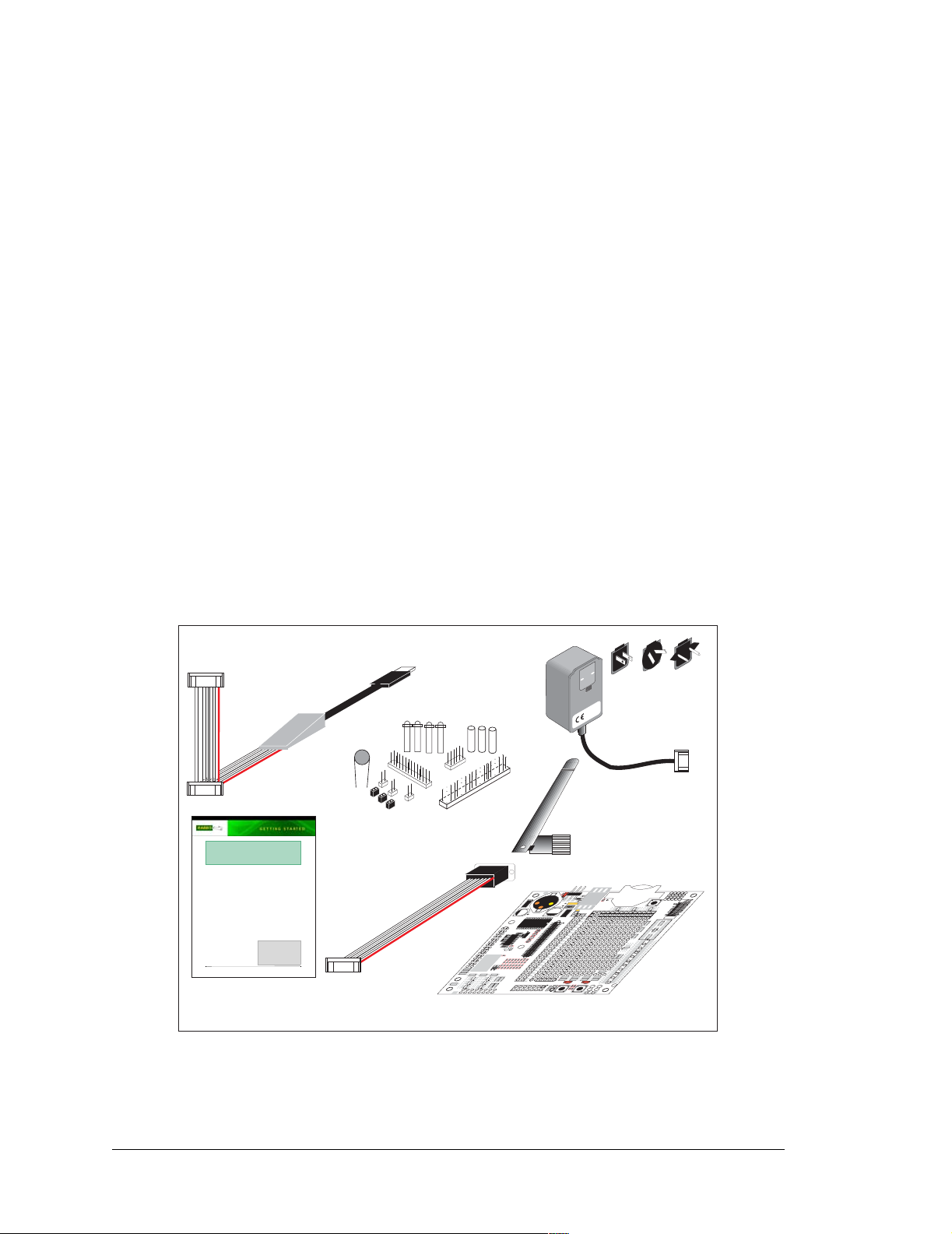
1.3.1 RCM5400W Development Kit
The RCM5400W Development Kit contains the hardware essentials you will need to use
the RCM5400W module. The items in the Development Kit and their use are as follows.
• RCM5400W module with 2.4 GHz dipole antenna.
• Prototyping Board.
• Universal AC adapter, 12 V DC, 1 A (includes Canada/Japan/U.S., Australia/N.Z.,
U.K., and European style plugs). Development Kits sold in North America ma y contain
an AC adapter with only a North American style plug.
• USB programming cable with 10-pin header.
• 10-pin header to DB9 serial cable.
• Dynamic C® CD-ROM, with complete product documentation on disk.
• Getting Started instructions.
• A bag of accessory parts for use on the Prototyping Board.
• Rabbit 5000 Processor Easy Reference poster.
• Registration card.
DIAG
PROG
Programming
Quick Start Guide
1. Install Dynamic C.
2. Attach antenna to RCM5400W RabbitCore module.
3. Install RCM440W module on Prototyping Board, connect programming cable to PC, connect AC
adapter.
4. Explore sample programs in the Dynamic C Samples\TCPIP\WiFi folder.
RabbitCore RCM5400W
The RCM5400W RabbitCore module provides Wi-Fi/802.11b/g functionality, allowing you to create a
low-cost, low-power, Wi-Fi based control and communications solution for your embedded system. These
Getting Started instructions included with the Development Kit will help you get your RCM5400W up and
running so that you can run the sample programs to explore its capabilities and develop your own
applications.
Development Kit Contents
The RCM5400W Development Kit contains the following items
RCM5400W module with 2.4 GHz dipole antenna..
•
• Prototyping Board.
• Universal AC adapter, 12 V DC, 1 A (includes Canada/Japan/U.S., Australia/N.Z., U.K., and European
style plugs). Development Kits sold in North America may contain an AC adapter with only a North
American style plug.
• USB programming cable with 10-pin header.
• 10-pin header to DB9 serial cable.
®
• Dynamic C
CD-ROM, with complete product documentation on disk.
• Getting Started instructions.
• Plastic and metal standoffs with 4-40 screws and washers.
• A bag of accessory parts for use on the Prototyping
Board.
• Rabbit 5000 Processor Easy Reference poster.
• Registration card.
Visit our online Rabbit store at www.rabbit.com/store/ for
the latest information on peripherals and accessories that
are available for the RCM5400W RabbitCore modules.
Rabbit, RabbitCore, Dynamic C and Digi are registered trademarks of Digi International Inc.
Getting Started
Instructions
Cable
®
Installing Dynamic C
Insert the CD from the Development Kit in
your PC’s CD-ROM drive. If the installation
does not auto-start, run the setup.exe pro-
gram in the root directory of the Dynamic C
CD. Install any Dynamic C modules after you
install Dynamic C
.
Accessory Parts for
Prototyping Board
Serial
Cable
RX43
7
4
X
R
J
RX97
RX55
RX49
3
1
3
4
X
X
U
U
2
1
4
3
X
9
X
8
U
U
X
R
7
3
X
U
3
UX3
6
X
R
Prototyping Board
Universal
AC Adapter
with Plugs
Antenna
PWR
R
1
J1
U1
DS1
2
C1
R
GND
GND
1
D
C2
1
P
J
4
3
V
C
C
C5
JP16
JP6
7
C18
1
JP5
0
C
2
JP12
C
U3
JP4
JP3
JP14
JP8
C16
JP7
JP18
JP9
JP10
9
1
C
R25
C15
6
2
R
Q1
PC7
5
9
1
1
2
0
7
1
1
2
1
R29
2
2
1
P
P
P
P
P
P
P
J
J
J
J
J
J
J
PE1
3
1
P
J
PE3
8
6
4
3
5
7
R20
R19
1
1
1
1
1
1
R
R
R
R
R
R
PE5
R10
7
R9
R8R6R4R3R5R
PE7
PD1
PD2
LN1
LN2
9
1
4
2
0
3
1
1
1
1
1
4
3
C8C7C
C
2
2
C
C
C
C
PD4
PD3
P
P
LN4
LN3
J
PD6
PD5
LN6
LN5
RX59
RX57
PD7
CVT
LN7
1
6
X
N
VREF
AGND
R
G
A
N
N
F
I
I
E
5
7
R
N
N
5
L
V
L
6
X
R
J3
T
D
N
N
N
I
I
I
V
N
6
4
2
C
G
N
N
N
A
L
L
L
3
.
J2
3
2
L1
+
D
C6
2
U
PB3
PB5
PB7
PC1
PC3
PC5
PE0
PE2
PE4
PE6
PD0
LN0
D
D
N
N
I
I
N
1
3
G
N
N
A
L
L
2
1
R
1
1
R
N
I
0
N
L
+5 V
2
P
GND
J
GND
/RST_OUT
/IORD
+3.3 V
RCM1
/IOWR
/RST_IN
VBAT
PA0
EXT
PA1
PA2
PA3
PA4
PA5
PA6
PA7
PB0
PB1
PB2
PB4
PB6
PC0
PC2
PC4
PC6
5
8
X
R
RX75
CX27
RX73
CX25
RX79
RX77
CX23
DS3
DS2
R21
R22
JP25
R24
R23
7
8
GND
1
1
2
2
R
R
GND
GND
S3S2
1
S1
BT1
RESET
C
D
UX49
UX47
RX83
RX11
5
4
X
U
UX10
7
1
RX67
X
C
UX12
UX14
9
2
X
C
UX16
X
UX4
X
R
T
D
C
X
X
R
T
D
N
G
J4
9
2
X
RX81
U
7
8
X
R
1
4
X
C
9
3
X
C
UX30
Figure 1. RCM5400W Development Kit
4 RabbitCore RCM5400W
Page 11

1.3.2 Software
The RCM5400W is programmed using version 10.40 or later of Dynamic C. A compatible
version is included on the Development Kit CD-ROM. This version of Dynamic C
includes the popular µC/OS-II real-time operating system, point-to-point protocol (PPP),
FAT file system, RabbitWeb, and other select libraries.
Rabbit also offers for purchase the Rabbit Embedded Security Pack featuring th e Secure
Sockets Layer (SSL) and a specific Advanced Encryption Standard (AES) library. In addition to the Web-based technical support included at no extra charge, a one-year telephonebased technical support subscription is also available for purchase. Visit our Web site at
www.rabbit.com for further information and complete documentation, or contact your
Rabbit sales representative or authorized distributor
1.3.3 Onlin e Documentation
The online documentation is installed along with Dynamic C, and an icon for the documentation menu is placed on the workstation’s desktop. Double-click this icon to reach the
menu. If the icon is missing, use your browser to find and load
default.htm in the docs
folder, found in the Dynamic C installation folder.
The latest versions of all documents are always available for free, unregistered download
from our Web sites as well.
OEM User’s Manual 5
Page 12

1.4 Certifications
The systems integrator and the end-user are ultimately responsible for the channel range
and power limits complying with the regulator y requirements of the co untry where the end
device will be used. Dynamic C function calls and sample programs illustrate how this is
achieved by selecting the country or region, which sets the channel range and power limits
automatically. See Section 6.2.4.1 for additional information and sample programs demonstrating how to configure an end device to meet the regulatory channel range and power
limit requirements.
Only RCM5400W modules bearing the FCC certification are certified for use in Wi-Fi
enabled end devices, and any applications must have been compiled using Dynamic C v.
10.40 or later. The certification is valid only for RCM5400W modules equipped with the
dipole antenna that is included with the modules, or a detachable antenna with a 60 cm
coaxial cable (Digi International part number 29000105). Changes or modifications to this
equipment not expressly approved by Digi International may void the user's authority to
operate this equipment.
In the event that these conditions cannot be met, then the FCC certification is no longer
considered valid and the FCC ID can not be used on the final product. In these circumstances, the systems integrator or end-user will be responsible for re-evaluating the end
device (including the transmitter) and obtaining a separate FCC certification.
NOTE: Any regulatory certification is voided if the RF shield on the RCM5400W
module is removed.
1.4.1 FCC Part 15 Class B
The RCM5400W RabbitCore module has been tested and found to comply with the l imits
for Class B digital devices pursuant to Part 15 Subpart B, of the FCC Rules. These limits
are designed to provide reasonable protection against harmful interference in a residential
environment. This equipment generates, uses, and can radiate radio frequency energy, and
if not installed and used in accordance with the instruction manual, may cause harmful
interference to radio communications. However, there is no guarantee that interference
will not occur in a particular installation. If this equipment does cause harmful interference to radio or television reception, which can be determined by turning the equipment
off and on, the user is encouraged to try and correct the interference by one or more of the
following measures:
• Reorient or relocate the receiving antenna.
• Increase the separation between the equipment and the receiver.
• Connect the equipment into an outlet on a circuit different from that to which the
receiver is connected.
• Consult the dealer or an experienced radio/TV technician for help.
6 RabbitCore RCM5400W
Page 13

Labeling Requirements (FCC 15.19)
FCC ID: VCB-E59C4472
This device complies with Part 15 of FCC rules. Operation is
subject to the following two conditions:
(1) this device may not cause harmful interference, and
(2) this device must accept any interference received, including
interference that may cause undesired operation.
If the FCC identification number is not visible when the module is installed insi de another
device, then the outside of the device into which the module is installed must also display
a label referring to the enclosed module or the device must be capable of displaying the
FCC identification number electronically. This exterior label can use wording such as the
following: “Contains Transmitter Module FCC ID: VCB-E59C4472” or “Contains FCC
ID: VCB-E59C4472.” Any similar wo rding t hat exp resses the same meaning may be used.
The following caption must be included with documentation for any device incorporating
the RCM5400W RabbitCore module.
Caution — Exposure to Radio-Frequency Radiation.
To comply with FCC RF exposure compliance requirements, for mobile
configurations, a separation distance of at least 20 cm must be maintained
between the antenna of this device and all persons.
This device must not be co-located or operating in conjunction with any
other antenna or transmitter.
1.4.2 Industry Canada Labeling
7143A-E59C4472
This Class B digital apparatus complies with Canadian standard
ICES-003.
Cet appareil numérique de la classe B est conforme à la norme
NMB-003 du Canada.
OEM User’s Manual 7
Page 14

1.4.3 Europe
The marking shall include as a minimum:
• the name of the manufacturer or his trademark;
• the type designation;
• equipment classification, (see below).
Receiver
Class
1
2
3
Highly reliable SRD communication media, e.g., serving human life
inherent systems (may result in a physical risk to a person).
Medium reliable SRD communication media, e.g., causing
inconvenience to persons that cannot be overcome by other means.
Standard reliable SRD communication media,e.g., inconvenience to
persons that can simply be overcome by other means.
Risk Assessment of Receiver Performance
NOTE: Manufacturers are recommended to declare the classification of their devices in
accordance with Table 2 and EN 300 440-2 [5] clause 4.2, as relevant. In particular,
where an SRD that may have inherent safe ty of human life i m pli ca ti ons , manufacturers
and users should pay particular attention to the potential for interference from other
systems operating in the same or adjacent bands.
Regulatory Mark ing
The equipment shall be marked, where applicable, in accordance with CEPT/ERC Recommendation 70-03 or Directive 1999/5/EC, whichever is applicable. Where this is not applicable, the equipment shall be marked in accordance with the National Regulatory
requirements.
8 RabbitCore RCM5400W
Page 15

2. GETTING S TARTED
This chapter describes the RC M540 0W hardw are i n m ore detai l, a nd
explains how to set up and use the accompanying Prototyping Board.
NOTE: This chapter (and this manual) assume that you have the RCM5400W Develop-
ment Kit. If you purchased an RCM5400W or RCM5450W module by itself, you will
have to adapt the information in this chapter and elsewhere to your test and development setup.
2.1 Install Dynamic C
To develop and debug programs for the RCM5400W series of modules (and for all other
Rabbit Semiconductor hardware), you must install and use Dynamic C.
If you have not yet installed Dynamic C version 10.40 (or a later version), do so now by
inserting the Dynamic C CD from the Development Kit in your PC’s CD-ROM drive. If
autorun is enabled, the CD installation will begin automatically.
If autorun is disabled or the installation does not start, use the Windows Start | Run menu
or Windows Disk Explorer to launch setup.exe from the root folder of the CD-ROM.
The installation program will guide you through the installation process. Most steps of the
process are self-explanatory.
Dynamic C uses a COM (serial ) port to communica te with the tar get deve lopment sy stem.
The installation allows you to choose the COM port that will be used. The default selection is COM1. You may select any available port for Dynamic C’s use. If you are not certain which port is available, select COM1. This selection can be changed later within
Dynamic C.
NOTE: The installation utility does not check the selected COM port in any way. Speci-
fying a port in u se by a not her device (mouse, modem, et c.) may l ea d t o a message such
as
"could not open serial port" when Dynamic C is started.
Once your installation is complete, you will have up to three new icons on your PC desktop. One icon is for Dynamic C, another opens the documentation menu, and the third is for
the Rabbit Field Utility , a tool used to download precompiled software to a target system.
If you have purchased any of the optional Dynamic C modules, install them after installing
Dynamic C. The modules may be installed in any order. You must install the modules in
the same directory where Dynamic C was installed.
OEM User’s Manual 9
Page 16
2.2 Hardware Connections
There are three steps to connecting the Prototyping Board for use with Dynamic C and the
sample programs:
1. Prepare the Prototyping Board for Development.
2. Attach the antenna to the RCM5400W module.
3. Attach the RCM5400W module to the Prototyping Board.
4. Connect the programming cable between the RCM5400W and the PC.
5. Connect the power supply to the Prototyping Board.
CAUTION: Provide ESD protection such as smocks and grounding straps on your
footwear.while assembling the RCM5400W module, installing it on another
board, and while making or removing any connections.
Remember to use ESD protection re gardl ess of whet her you are worki ng with th e
RCM5400W module on the Prototyping Board or in your own OEM application.
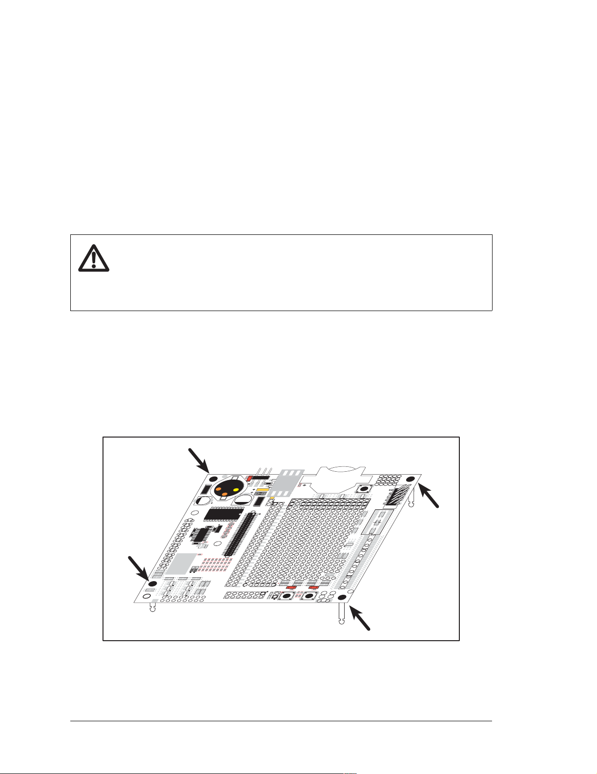
2.2.1 Step 1 — Prepare the Prototyping Board for Development
Snap in four of the plastic standoffs supplied in the bag of accessory parts from the Development Kit in the holes at the corners as shown in Figure 2.
NOTE: Be sure to use the hole th at is point ed ou t toward s the bot tom left of the Pr ototyp -
ing Board since the hol e below it is used f or a stan doff when mounting the RCM5400W
on the Prototyping Board.
PWR
R
1
J1
U1
DS1
C1
GND
D1
C5
JP16
C18
17
JP5
C
20
JP12
C
U3
JP4
JP3
JP14
JP8
C16
JP7
JP18
JP9
JP10
19
C
R25
C15
26
R
Q1
R29
JP11JP15JP19JP21JP22
R20
R18R16R14R13R15R
R10
7
RX43
47
X
R
RX97
RX49
X33U
U
31
X
89
X
R
UX3
R8R6R4R3R5R
9
11
10
C8C7C
C
C
C14C12C
JP24JP23
RX59
RX57
RX55
41
X
U
42
X
U
37
X
U
PD7
LN7
X61
VREF
R
65
X
R
J3
X63
R
GND
C2
JP1
3
C
2
L1
D
C6
JP6
JP20
JP17
PE1
13
JP
PE3
R19
17
PE5
R9
PE7
PD1
LN1
13
PD3
LN3
PD5
LN5
V
D
N
C
G
A
2
U
PC1
PC3
PC5
PC7
LN2
PD4
LN4
PD6
LN6
CVT
AGND
F
E
7INLN5INLN3INLN1IN
R
LN
T
V
6INLN4INLN2INLN0IN
LN
2
JP
/RST_OUT
RCM1
/IOWR
VBAT
EXT
PA1
PA3
PA5
PA7
PB1
PB2
PB3
PB4
PB5
PB6
PB7
PC0
PC2
PC4
PC6
PE0
PE2
PE4
PE6
PD0
LN0
PD2
D
N
AG
D
N
AG
11
R
Figure 2. Insert Standoffs
2
R
4
C
J2
3.3 V
+
GND
/IORD
/RST_IN
PA0
PA2
PA4
PA6
PB0
RX75
CX25
DS2
JP25
12
R
UX47
+5 V
GND
+3.3 V
85
RX
CX27
RX73
R23
RX79
RX77
CX23
DS3
R21
R22
R24
1
GND
1
28
R27R
GND
S3S2
1
S1
BT1
RESET
D
UX49
UX4
RX81
87
X
R
RX83
X39
C
RX11
X45
U
RX67
X17
C
UX14
29
X
C
UX16
GND
UX30
UX10
UX12
XC
TX
R
C
XD
R
TX
D
N
G
J4
29
UX
X41
C
10 RabbitCore RCM5400W
Page 17
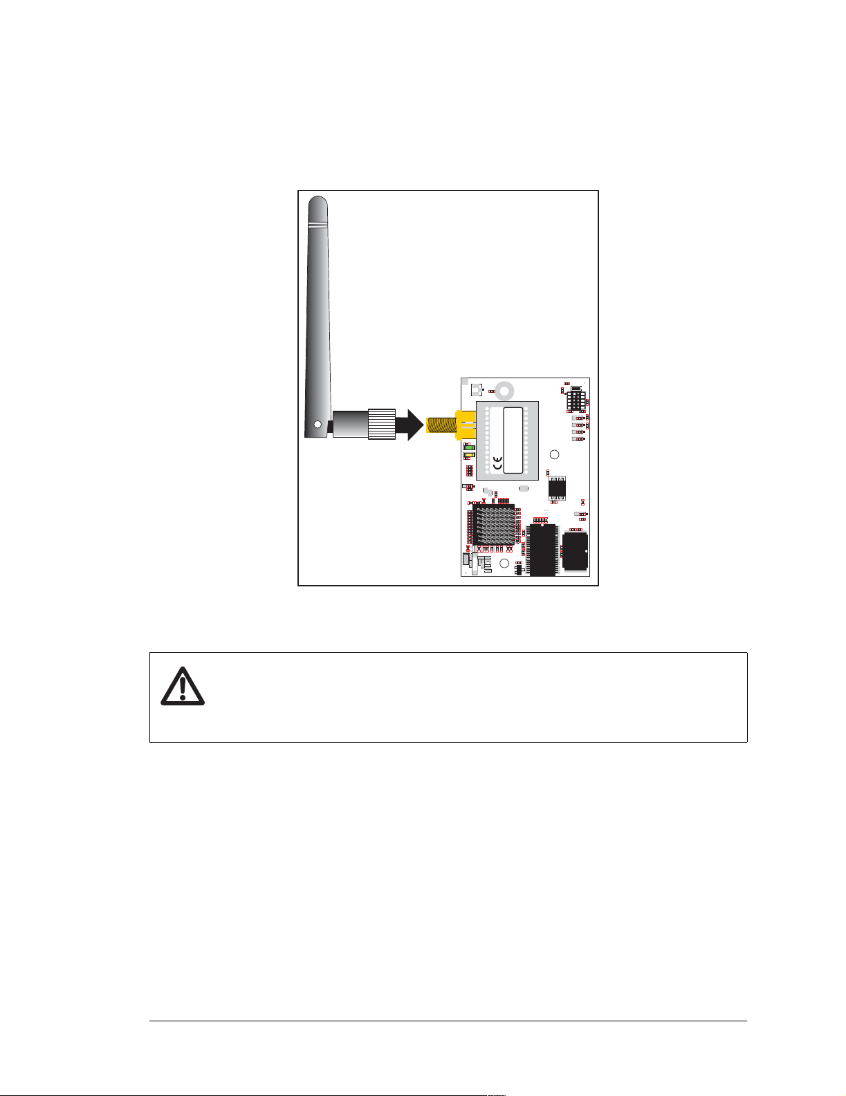
2.2.2 Step 2 — Attach the Antenna to the RCM5400W Module
Attach the antenna to the antenna SMA connector on the RCM5400W as shown in
Figure 3.
FCC ID: VCBE59C4472
P1
R31
P2
C144
U19
C136
C120
L22
C135
C119
T1
C118
C121
LINK
DS2
C115
R37
C134
C105
L19
C104
C139
DS1
ACT
C103
C107
4
R33
C137
U20
R79
C108
C138
R80
C110
3
2
TP22
TP24
TP23
TP21
R65
JP6
R32
C48
C79
C37
C36
C49
C50
C51
C52
C54
C55
C39
C40
C43
C44
C46
C47
C53
C57
C64
C16
U9
C58
1
C56
R22
R17
R23
R16
R11
R25
R24
R18
R13
C18
U10
3
2
C21
Y3
C19
R20
R21
Y2
IC: 7143AE59C4472
E1 (Base)
E2 (Cover)
U21
901-0190
C117
C114
L21
C116
C106
L20
U18
INTERNATIONAL
C112
®
C111
R19
DIGI
C102
R64
RABBIT RCM5400W
C113
L18
TP26
TP25
TP28
TP27
C80
C45
R61
R59
R58
R36
C41
C42
R60
C38
C33
C34
C32
R34
C35
C31
U1
C28
C3
C30
C29
C4
C14
Q1
C73
C2
R91
J2
R3
R5
R4
R2
JP1
JP3
R1
JP2 JP4
U17
R84
C100
JP5
R83
U2
C10
C9
U4
U12
C6
C5
C27
C26
Figure 3. Attach the Antenna to the RCM5400W Module
CAUTION: Do not remove the RF shield by the antenna since any attempt to
remove the shield will damage the RF circuits underneath it.
Any regulatory certif ication is voi ded if the RF shield on t he RCM5400W module
is removed.
OEM User’s Manual 11
Page 18
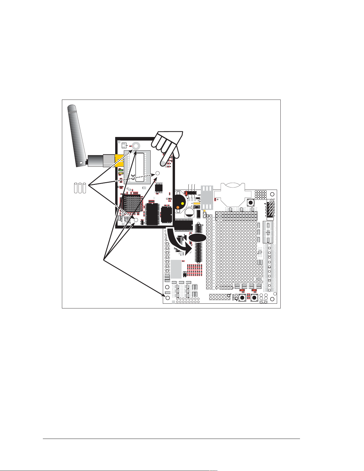
2.2.3 Step 3 — Attach Module to Prototyping Board
Turn the RCM5400W module so that the mounting holes line up with the corresponding
holes on the Prototyping Board. Insert the metal standoffs as shown in Figure 4, secure
them from the bottom using the 4-40 × 3/16 screws and washers, then insert the module’s
header J1 on the bottom side into socket RCM1 on the Prototyping Board.
FCC ID: VCBE59C4472
IC: 7143AE59C4472
E1 (Base)
E2 (Cover)
U21
901-0190
901-0190
C117
C114
L21
C116
C106
L20
U18
INTERNATIONAL
INTERNATIONAL
C112
®
®
C111
RCM5400W
R19
DIGI
DIGI
C102
R64
RABBIT RCM5400W
C113
L18
TP26
TP25
TP28
TP27
C80
C30
C100
C45
R61
R59
R58
R36
C41
C42
R60
U2
C38
C33
C34
C32
R34
C35
C31
U1
C28
C3
C4
C14
Q1
C73
C2
R91
J2
R3
R5
R4
R2
JP1
JP3
R1
JP2 JP4
U17
C10
D1
U12
C6
C5
C26
RX47
RCM5400W
PWR
R1
R84
JP5
R83
C9
U4
C5
L1
C6
C27
C18
C17
U3
C16
C19 C20
R25
C15
Q1
R29
R20
RX43
RX97
R10
JP24
RX55
RX49
UX41
UX33UX31
RX89
UX37 UX42
UX3
JP16
JP6
JP5
JP12
JP4
JP3
JP14
JP8
JP7
JP18
JP9
JP10
R26
JP11
C14
JP23
RX57
DS1
GND
C2
U2
RCM1
JP15
JP19
JP21
R18
R16
R14
R13
R8R6R4R3R5
C8C7C9
C12
C10
RX59
RX63
J1
U1
C1
D2
JP22
R2
GND
JP1
C4
C3
J2
+3.3 V
JP2
/RST_OUT
RCM1
/IOWR
VBAT
EXT
PA1
PA3
PA5
PA7
PB1
PB3
PB5
PB7
PC1
PC3
PC5
PC7
JP20
JP17
PE1
JP13
PE3
R19
R15
R17
PE5
R9
R7
PE7
PD1
LN1
C11
C13
PD3
LN3
PD5
LN5
PD7
LN7
VREF
RX61
RX65
J3
UX47
+5 V
GND
GND
/IORD
+3.3 V
/RST_IN
PA0
PA2
PA4
PA6
PB0
PB2
PB4
PB6
PC0
PC2
PC4
PC6
PE0
PE2
PE4
PE6
PD0
LN0
PD2
LN2
PD4
LN4
PD6
LN6
CVT
AGND
AGND
VREF
LN7IN
LN5IN
LN3IN
LN1IN
CVT
AGND
LN6IN
LN4IN
LN2IN
1
S1
BT1
RESET
UX49
UX4
RXD TXD
TXC RXC
GND
RX81
RX83
RX11
RX67
RX75
CX25
DS2
JP25
AGND
R12
R11
LN0IN
RX85
CX27
RX73
RX77
RX79
CX23
DS3
R21
R22
R24
R23
1
R27
R28
GND
S3S2
J4
UX29
RX87
CX41
CX39
UX30
UX45
UX10
CX17
UX12
UX14
CX29
UX16
GND
1
GND
Insert standoffs
between
mounting holes and
Prototyping Board.
Line up mounting
holes with holes
on Prototyping Board.
P1
R31
P2
C144
U19
C136
C120
L22
C135
C119
T1
C118
C121
LINK
DS2
C115
R37
C134
C105
L19
C104
C139
DS1
ACT
C103
C107
4
R33
C137
U20
R79
C108
C138
R80
C110
3
2
TP22
TP24
TP23
TP21
R65
JP6
R32
C48
C79
C37
C36
C49
C50
C51
C52
C54
C55
C39
C40
C43
C44
C46
C47
C53
C57
C64
C16
U9
C29
C58
1
C56
R22
R17
R23
R16
R11
R25
R24
R18
R13
C18
U10
3
2
C21
Y3
C19
R20
R21
Y2
Figure 4. Install the Module on the Prototyping Board
NOTE: It is important that you line up the pins on header J1 of the module exactly with
socket RCM1 on the Pr ototyp ing Boa rd. The header pins may bec ome bent or da maged
if the pin alignment is offset, and the module will not work. Permanent electrical damage to the module may also result if a misaligned module is powered up.
Press the module’s pins gently into the Prototyping Board socket—press down in the area
above the header pins. For additional integrity, you may secure the RCM5400W to the
standoffs from the top using the remaining three screws and washers.
12 RabbitCore RCM5400W
Page 19
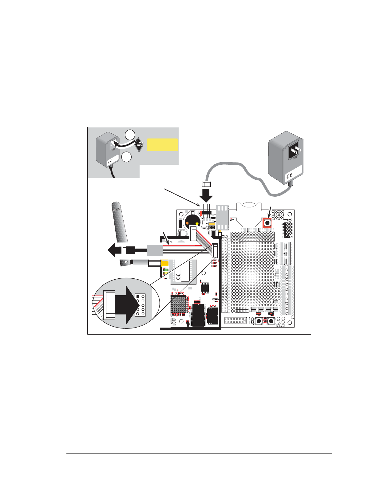
2.2.4 Step 4 — Connect Programming Cable
The programming cable connects the module to the PC running Dynamic C to download
programs and to monitor the module during debugging.
Connect the 10-pin connector of the programming cable labeled
PROG to header J2 on
the RCM5400W as shown in Figure 5. Be sure to orient the marked (usually red) edge of
the cable towards pin 1 of the connector. (Do not use the DIAG connector, which is used
for a normal serial connection.)
Insert tab into slot
1
Assemble
AC Adapter
Snap plug into place
2
AC Adapter
3-pin
power connector
To
PC USB port
PROG
Programming
Cable
Colored
edge
C52
C54
C55
C39
J2
C40
C43
C44
C46
C47
C53
C57
C64
1
2
J1
PWR
R1
J1
U1
DS1
C1
U3
901-0190
901-0190
C19 C20
C112
C102
TP28
TP27
C45
C41
C42
C38
C33
C34
C32
C35
UX33UX31
C3
C4
C14
UX3
Q1
DIAG
L1
E1 (Base)
E2 (Cover)
C18
C15
R19
Q1
TP26
TP25
R58
R36
RX55
R34
GND
C2
D2
C6
FCC ID: VCBE59C4472
IC: 7143AE59C4472
C73
C2
R91
J2
U2
JP16
JP6
JP1
JP5
C17
JP12
JP3
JP4
JP3
JP2 JP4
JP14
JP8
C16
JP7
JP18
JP9
JP10
R25
R26
R64
U17
R29
JP11
JP15
JP19
JP21
JP22
R20
R18
R16
R14
R13
R10
C100
R8R6R4R3R5
R61
R59
C8C7C9
R60
C14
C12
C10
U2
JP24
JP23
C10
RX59
RX57
U12
C6
C5
C26
UX37 UX42 UX41
RX63
D1
C5
P1
R31
P2
C144
U19
C136
C120
L22
U21
C135
C119
C117
T1
C114
C118
C121
LINK
C105
C104
C139
ACT
4
C137
U20
C138
3
2
TP22
TP23
TP21
C49
C50
C56
R22
R17
R23
R16
C21
R20
Y2
L21
C116
C115
C134
C106
L19
L20
U18
INTERNATIONAL
INTERNATIONAL
®
®
C103
C107
C111
RCM5400W
DIGI
DIGI
C108
RABBIT RCM5400W
C110
C113
L18
TP24
R65
C48
C79
C37
C36
C80
RX43
RX47
RX97
RX49
C31
U1
C28
C30
C29
C58
R11
R25
R24
RX89
R13
C18
U10
R21
DS2
R37
DS1
R33
R79
R80
JP6
R32
C51
C16
U9
R18
3
Y3
C19
RCM1
R5
JP20
R15
GND
PROG
R4
R17
R7
JP5
RX61
RX65
/RST_OUT
JP17
C11
R2
JP1
C4
C3
J2
+3.3 V
JP2
/IOWR
VBAT
EXT
PA1
R3
PA3
R2
PA5
PA7
R1
PB1
PB3
PB5
PB7
PC1
PC3
PC5
PC7
PE1
JP13
PE3
R19
R84
PE5
R9
PE7
PD1
LN1
R83
C13
PD3
LN3
PD5
C9
LN5
U4
PD7
LN7
VREF
C27
J3
UX47
+5 V
GND
GND
/IORD
+3.3 V
/RST_IN
PA0
PA2
PA4
PA6
PB0
PB2
PB4
PB6
PC0
PC2
PC4
PC6
PE0
PE2
PE4
PE6
PD0
LN0
PD2
LN2
PD4
LN4
PD6
LN6
CVT
AGND
AGND
VREF
LN7IN
LN5IN
LN3IN
LN1IN
CVT
AGND
LN6IN
LN4IN
LN2IN
RESET
1
S1
BT1
RESET
UX49
UX4
RXD TXD
TXC RXC
GND
RX81
RX83
RX11
RX67
RX75
CX25
DS2
JP25
AGND
R12
R11
LN0IN
RX85
CX27
RX73
RX77
RX79
CX23
DS3
R21
R22
R24
R23
1
R27
R28
GND
S3S2
J4
UX29
RX87
CX41
CX39
UX30
UX45
UX10
CX17
UX12
UX14
CX29
UX16
GND
1
GND
Figure 5. Connect Programming Cable and Power Supply
Connect the other end of the programming cable to an available USB port on your PC or
workstation.
Your PC should recognize the new USB hardware, and the LEDs in the shrink-wrapped
area of the USB programming cable will flash — if you get an error message, you will
have to install USB dr i ve rs . Drivers for Windows XP are available in the Dynamic C
Drivers\Rabbit USB Programming Cable\WinXP_2K folder — double-click
DPInst.exe to install the USB drivers. Drivers for other operating systems are available
online at www.ftdichip.com/Drivers/VCP.htm.
OEM User’s Manual 13
Page 20

2.2.5 Step 5 — Connect Power
Once all the other connections have been made, you can connect power to the Prototyping
Board.
If you have the universal AC adapter, p repare the AC adapter for the country where it will
be used by selecti n g th e a pp ro p ri at e p lu g . Snap in the top of the plug assembly into the slot
at the top of the AC adapter as shown in Figure 5, then press down on the plug until it
clicks into place.
Connect the AC adapter to 3-pin header J1 on the Prototyping Board as shown in Figure 5
above. The connector may be attached either way as long as it is not offset to one side—
the center pin of J1 is always connected to the positive terminal, and either edge pin is
ground.
Plug in the AC adapter. The
PWR LED on the Prototyping Board next to the power con-
nector at J1 should light up. The RCM5400W and the Prototyping Board are now ready to
be used.
NOTE: A RESET button is provided on the Pro totyping Bo ard next t o the batt ery holder
to allow a hardware reset without disconnecting power.
14 RabbitCore RCM5400W
Page 21
2.3 Run a Sample Program
If you already have Dynamic C installed, you are now ready to test your programming
connections by running a sample program. Start Dynamic C by double-clicking on the
Dynamic C icon on your desktop or in your Start menu. Select Store Program in Flash
on the “Compiler” tab in the Dynamic C Options > Project Options menu. Then click
on the “Communications” tab and verify that Use USB to Serial Converter is selected to
support the USB programming cable. Click OK.
You may have to select the COM port assigned to the USB programming cable on your
PC. In Dynamic C, select Options > Project Options, then select this COM port on the
“Communications” tab, then click OK. You may type the COM port number followed by
Enter on your computer keyboard if the COM port number is outside the range on the
dropdown menu.
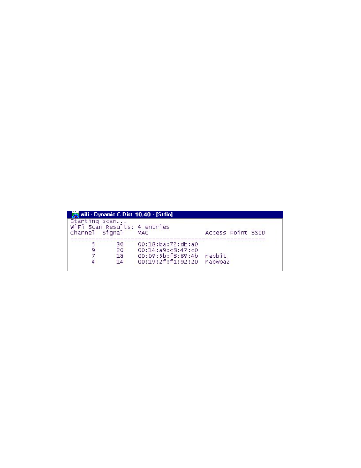
Now find the WIFISCAN.C sample program in the Dynamic C Samples\WiFi folder,
open it with the File menu, then compile and run the sample program by pressing F9.
The Dynamic C STDIO window will display Starting scan...., and will display a list
of access points/ad-hoc hosts as shown here.
The following fields are shown in the Dynamic C STDIO window.
• Channel—the channel the access point is on (1–11).
• Signal—the signal strength of the access point.
• MAC—the hardware (MAC) address of access point.
• Access Point SSID—the SSID the access point is using.
OEM User’s Manual 15
Page 22

2.3.1 Troubleshooting
If you receive the message Could Not Open Serial Port, check that the COM port
assigned to the USB programming cable was identified and set up in Dynamic C as
described in the preceding section.
If you receive the message No Rabbit Processor Detected, the programming
cable may be connected to the wrong COM port, a connection may be faulty, or the tar get
system may not be powered up. First, check to see that the power LED on the Prototyping
Board is lit. If the LED is lit, ch eck both ends of the programm ing cable to ensure tha t it is
firmly plugged into the PC and the programming header on the RCM5400W with the
marked (colored) edge of the programming cable towards pin 1 of the programming
header. Ensure that the module is firmly and correctly installed in its connectors on the
Prototyping Board.
If Dynamic C appears to compile the BIOS successfully, but you then receive a communication error message when you compile and load a sample program, it is possible that your
PC cannot handle the higher program-loading baud rate. Try changing the maximum
download rate to a slower baud rate as follows.
• Locate the
Options > Project Opti ons menu. Select a slower Max download baud rate. Click OK
Serial Options dialog on the “Communications” tab in the Dynamic C
to save.
If a program compiles and loads, but then loses target communication before you can
begin debugging, it is possible that your PC cannot handle the default debugging baud
rate. Try lowering the debugging baud rate as follows.
• Locate the Serial Options dialog on the “Communications” tab in the Dynamic C
Options > Project Options menu. Choose a lower debug baud rate. Click OK to save.
Press <Ctrl-Y> to force Dyn a m i c C to re compile th e B I O S . You should receive a Bios
compiled successfully
message once this step is completed successfully.
16 RabbitCore RCM5400W
Page 23

2.4 Where Do I Go From Here?
If the sample program ran fine, you are now ready to go on to the sample programs in
Chapter 3 and to develop your own applications. The sample programs can be easily modified for your own use. The user's manual also provides complete hardware reference
information and software function calls for the RCM5400W series of modules and the
Prototyping Board.
For advanced development topics, refer to the Dynamic C User’s Manual, also in the
online documentation set.
2.4.1 Technical Support
NOTE: If you purchased your RCM5400W or RCM5450W through a distributor or
through a Rabbit partner, contact the distributor or partner first for technical support.
If there are any problems at this point:
• Use the Dynamic C Help menu to get further assistance with Dynamic C.
• Check the Rabbit Technical Bulletin Board and forums at www.rabbit.com/support/bb/
and at www.rabbit.com/forums/.
• Use the Technical Support e-mail form at www.rabbit.com/support/.
OEM User’s Manual 17
Page 24

18 RabbitCore RCM5400W
Page 25

3. RUNNING SAMPLE PROGRAMS
To develop and debug programs for the RCM5400W (and for all
other Rabbit hardware), you must install and use Dynamic C.
This chapter provides a tour of its m ajor features with respect to
the RCM5400W modules.
3.1 Introduction
To help familiarize you with the RCM5400W modules, Dynamic C includes several sample programs. Loading, executing and studying these programs will give you a solid
hands-on overview of the RCM5400W’s capabilities, as well as a quick start with
Dynamic C as an application development tool.
This chapter provides sam ple programs t hat illust rate the digital I/O and s erial capabil ities
of the RCM5400W RabbitCore module. Section 6.2.4 discusses the sample programs that
illustrate the Wi-Fi features.
NOTE:
In order to run the sample programs discussed in this chapter and elsewhere in this manual,
1. Your module must be plugged in to the Prototyping Board as described in Chapter 2,
“Getting Started.”
2. Dynamic C must be installed and running on your PC.
3. The programming cable must connect the programming header on the module to your
PC.
4. Power must be applied to the module through the Prototyping Board.
Refer to Chapter 2, “Getting Started,” if you need further information on these steps.
To run a sample program, open it with the File menu, then compile and run it by pressing
F9.
Each sample program has comments that describe the purpose and function of the program. Follow the instructions at the beginning of the sample program.
Complete information on Dynamic C is provided in the Dynamic C User’s Manual.
The sample programs
language
for a suggested reading list.
.
If you do not, see the introductory pages of the Dynamic C User’s Manual
assume that you have at least an elementary grasp of the C
OEM User’s Manual 19
Page 26
3.2 Sample Programs
Of the many sample programs included with Dynamic C, several are specific to the
RCM5400W modules. These programs will be found in the SAMPLES\RCM5400W folder.
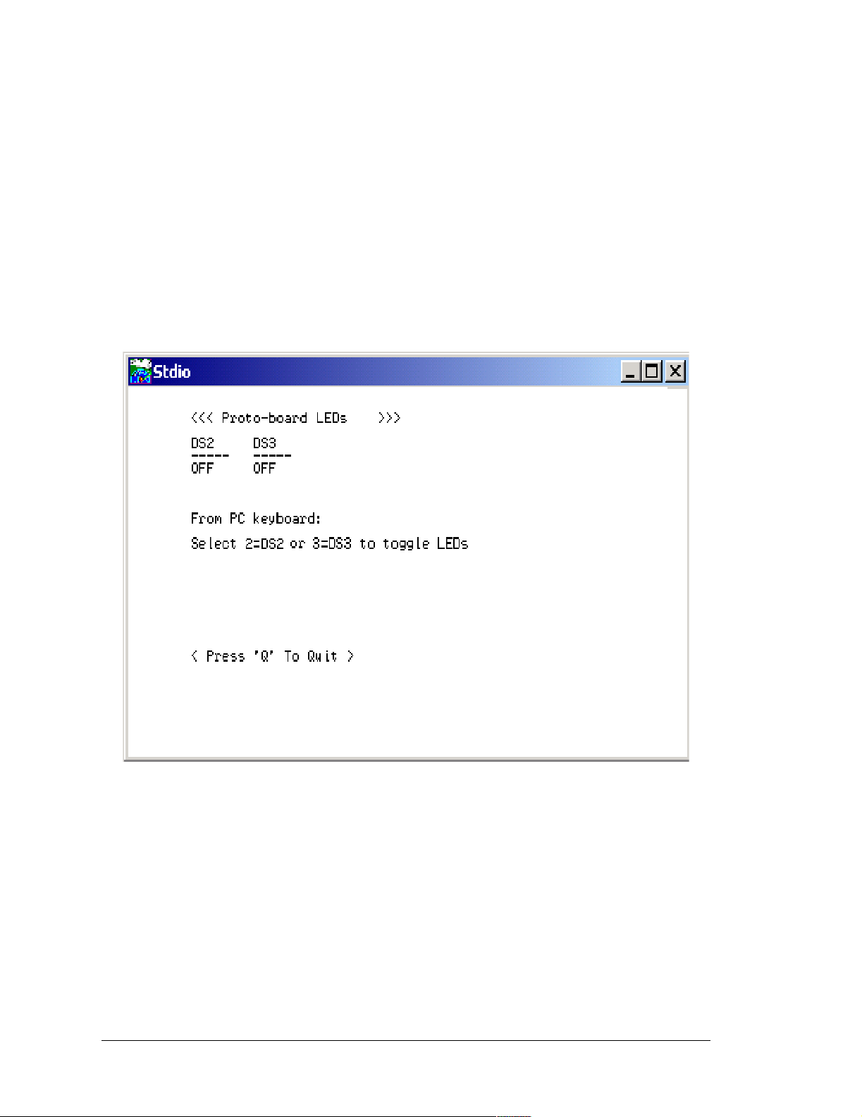
• CONTROLLED.C—Demonstrates use of the digital outputs by having you turn LEDs
DS2 and DS3 on the Prototyping Board on or off from the STDIO window on your PC.
Parallel Port B bit 2 = LED DS2
Parallel Port B bit 3 = LED DS3
Once you compile and run CONTROLLED.C, the following display will appear in the
Dynamic C STDIO window.
Press “2” or “3” on your keyboard to select LED DS2 or DS3 on the Prototyping
Board. Then follow the prompt in the Dynamic C STDIO window to turn the LED ON
or OFF. A logic low will light up the LED you selected.
• FLASHLED1.C—demonstrates the use of assembly language to flash LEDs DS2 and
DS3 on the Prototyping Board at different rates. Once you have compiled and run this
program, LEDs DS2 and DS3 will flash on/off at different rates.
• FLASHLED2.C—demonstrates the use of cofunctions and costatements to flash LEDs
DS2 and DS3 on the Prototyping Board at different rates. Once you have compiled and
run this program, LEDs DS2 and DS3 will flash on/off at different rates.
20 RabbitCore RCM5400W
Page 27

• TAMPERDETECTION.C—demonstrates how to detect an attempt to enter the bootstrap
mode. When an attempt is detected, the battery-backed onchip-encryption RAM on the
Rabbit 5000 is erased. This battery-backed onchip-encryption RAM can be useful to
store data such as an AES encryption key from a remote location.
This sample program shows how to load and read the battery-backed onchip-encryption
RAM and how to enable a visual indicator.
Once this sample is compiled and running (you pressed the
F9 key while the sample
program is open), remove the programming cable and press the reset button on the
Prototyping Board to reset the module. LEDs DS2 and DS3 will be flashing on and off.
Now press switch S2 to load the battery-backed RAM with the encryption key. The
LEDs are now on continuously. Notice that the LEDs will stay on even when you press
the reset button on the Prototyping Board.
Reconnect the programming cable briefly and unplug it again to simulate an attempt to
access the onchip-encryption RAM. The LEDs will be flashing because the batterybacked onchip-encryption RAM has been erased. Notice that the LEDs will continue
flashing even when you press the reset button on the Prototyping Board.
You may press switch S2 again and repeat the last steps to watch the LEDs.
• TOGGLESWITCH.C—demonstrates the use of costatements to detect switch presses
using the press-and-release method of debouncing. LEDs DS2 and DS3 on the Prototyping Board are turned on and off when you press switches S2 and S3. S2 and S3 are
controlled by PB4 and PB5 respectively.
Once you have loaded and executed these five programs and have an understanding of
how Dynamic C and the RCM5400W modules interact, you can move on and try the other
sample programs, or begin building your own.
OEM User’s Manual 21
Page 28

3.2.1 Use of Serial Flash
The following sample programs can be found in the SAMPLES\RCM5400W\Serial_Flash
folder.
• SERIAL_FLASHLOG.C—This program runs a simple Web server and stores a log of
hits on the home page of the serial flash “server.” This log can be viewed and cleared
from a browser at http://10.10.6.100/. You will likely have to first “configure” your network interface card for a “10Base-T Half-Duplex,” “100Base-T Half-Duplex,” or an
“Auto-Negotiation” connection on the “Advanced” tab, which is accessed from the
control panel (
Connections
Start > Settings > Control Panel) by choosing Network
.
• SFLASH_INSPECT.C—This program is a handy utility for inspect ing the contents of a
serial flash chip. When the sample program starts running, it attempts to initialize a
serial flash chip on Serial Port B. Once a serial flash chip is found, the user can perform
five different commands to print out the contents of a specified page, set all bytes on
the specified page to a single random value, clear (set to zero) all the bytes in a specified page, set all bytes on the specified page to a given value, or save user-specified text
to a selected page.
22 RabbitCore RCM5400W
Page 29
3.2.2 Serial Communication
The following sample programs are found in the SAMPLES\RCM5400W\SERIAL folder.
FLOWCONTROL.C—This program demonstrates how to configure Serial Port D for
•
CTS/R TS flow control with serial data coming from Serial Port C (TxC) at 1 15, 200 bps .
The serial data received are displayed in the STDIO window.
To set up the Prototyping Board, you will need to tie TxD and RxD
together on the RS-232 header at J4, and you will also tie TxC and
RxC together using the jumpers supplied in the Development Kit as
RxC TxC
TxD RxD
GND
shown in the diagram.
A repeating triangular pattern should print out in the STDIO window.
The program will periodically switch flow contr ol on or off to demonstrate th e eff ect of
flow control.
If you have two Prototyping Boards with modules, run this sample program on the
sending board, then disconnect the programming cable and reset the sending board so
that the module is operating in the Run mode. Connect TxC, TxD, and GND on the
sending board to RxC, RxD, and GND on the other board, then, with the programming
cable attached to the other module, run the sample program.
• PARITY.C—This program demonstrates the use of parity modes by
RxC
TxD
TxC
RxD GND
repeatedly sending byte values 0–127 from Serial Port C to Serial Port D.
The program will switch between generating parity or not on Serial
Port C. Serial Port D will always be checking parity, so parity errors
should occur during every other sequence.
J4
J4
To set up the Prototyping Board, you will need to tie TxC and RxD together on the
RS-232 header at J4 using one of the jumpers supplied in the Development Kit as
shown in the diagram.
The Dynamic C STDIO window will display the error sequence.
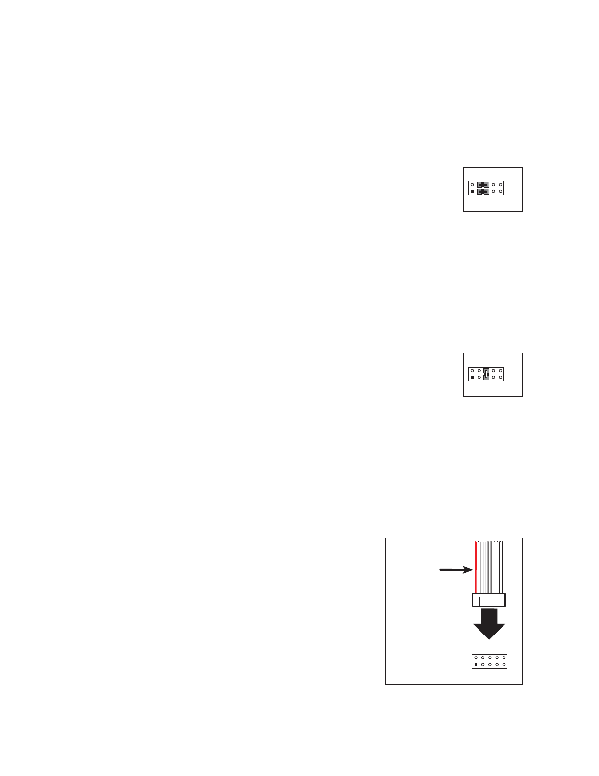
• SERDMA.C—This program demonstrates using DMA to transfer data from a circ ular
buffer to the serial port and vice versa. The Dynamic C
STDIO window is used to view or
clear the buffer.
Before you compile and run the sample program, you
will need to connect the RS-232 he ade r a t J4 to y our PC
as shown in the diagram using the serial to DB9 cable
supplied in the Development Kit.
Colored
edge
Once you have compiled and run the sample program,
start Tera Term or another terminal emulation program
to connect to the selected PC serial port at a baud rate of
115,200 bps. You can observe the output in the Dynamic C
STDIO window as you type in T e ra Term, and you can
also use the Dynamic C STDIO window to clear the
buffer.
J4
RxC
TxD
TxC
RxD
The Tera Term utility can be downloaded from
hp.vector.co.jp/authors/VA002416/teraterm.html.
GND
OEM User’s Manual 23
Page 30

• SIMPLE3WIRE.C—This program demonstrates basic RS-232 serial
communication. Lower case characters are sent on TxC, and are
received by RxD. The received characters are converted to upper case
and are sent out on TxD, are received on RxC, and are displayed in the
Dynamic C
STDIO window.
RxC TxC
TxD RxD
J4
GND
To set up the Prototyping Board, you will need to tie TxD and RxC together on the
RS-232 header at J4, and you will also tie RxD and TxC together using the jumpers
supplied in the Development Kit as shown in the diagram.
• SIMPLE5WIRE.C—This program demonstrates 5-wire RS-232 serial communication
with flow control on Serial Port D and data flow on Serial Port C.
To set up the Prototyping Board, you will need to tie TxD and RxD
together on the RS-232 header at J4, and you will also tie TxC and
RxC together using the jumpers supplied in the Development Kit as
RxC TxC
TxD RxD
J4
GND
shown in the diagram.
Once you have compiled and run this program, you can test flow con-
trol by disconnecting the TxD jumper from RxD while the program is running. Characters will no longer appear in the STDIO window, and will display again once TxD is
connected back to RxD.
If you have two Prototyping Boards with modules, run this sample program on the
sending board, then disconnect the programming cable and reset the sending board so
that the module is operating in the Run mode. Connect TxC, TxD, and GND on the
sending board to RxC, RxD, and GND on the other board, then, with the programming
cable attached to the other module, run the sample program. Once you have compiled
and run this program, you can test flow control by disconnecting TxD from RxD as
before while the program is running. Since the J4 header locations on the two Prototyping
Boards are connected with wires, there are no slip-on jumpers at J4 on either Pr ototyping
Board.
• SWITCHCHAR.C—This program demonstrates transmitting and then receiving an
ASCII string on Serial Ports C and D. It also displays the serial data received from both
ports in the STDIO window.
To set up the Prototyping Board, you will need to tie TxD and RxC
together on the RS-232 header at J4, and you will also tie RxD and
TxC together using the jumpers supplied in the Development Kit as
shown in the diagram.
RxC TxC
TxD RxD
J4
GND
Once you have compiled and run this program, press and release
switches S2 and S3 on the Prototyping Board. The data sent between the serial ports
will be displayed in the STDIO window.
24 RabbitCore RCM5400W
Page 31

3.2.3 Real-Time Clock
If you plan to use the real-time clock functionality in your application, you will need to set
the real-time clock. Use the SETRTCKB.C sample program from the Dynamic C
SAMPLES\RTCLOCK folder, and follow the onscreen prompts. The RTC_TEST.C sample
program in the Dynamic C SAMPLES\RTCLOCK folder provides additional examples of
how to read and set the real-time clock.
OEM User’s Manual 25
Page 32

26 RabbitCore RCM5400W
Page 33

4. HARDWARE REFERENCE
Chapter 4 describes the hardware components and principal hardware
subsystems of the RCM5400W. Appendix A, “RCM5400W Specifications,” provides complete physical and electrical specifications.
Figure 6 shows the Rabbit-based subsystems designed into the RCM5400W.
Wi-Fi
Serial
Flash
SRAM
Fast
SRAM
32 kHz
RABBIT
osc
5000
Program
Flash
73.73 MHz
osc
®
Customer-specific
applications
CMOS-level signals
Level
converter
RS-232, RS-485
serial communication
drivers on motherboard
RabbitCore Module
Figure 6. RCM5400W Subsystems
The 73.73 MHz frequency shown for the RCM5400W is generated using a 36.864 MHz
crystal with the Rabbit 5000 clock doubler enabled.
OEM User’s Manual 27
Page 34

4.1 RCM5400W Digital Inputs and Outputs
Figure 7 shows the RCM5400W pinouts for header J1.
J1
VIN
/RESET_OUT
/IOWR
VBAT_EXT
PA1
PA3
PA5
PA7
PB1/CLKA
PB3
PB5
PB7
PC1
PC3
PC5/RXB
PC7/RXA
PE1
PE3
PE5/SMODE0*
PE7/STATUS
PD1
PD3
PD5
PD7
n.c.
* These pins are normally n.c.
n.c. = not connected
GND
/IORD
/RESET_IN
PA0
PA2
PA4
PA6
PB0/SCLK
PB2
PB4
PB6
PC0
PC2
PC4/TXB
PC6/TXA
PE0/n.c.
PE2
PE4
PE6/SMODE1*
PD0
PD2
PD4
PD6
n.c.
GND
These pinouts are as seen on
Note:
the Bottom Side of the module.
Figure 7. RCM5400W Pinout
Headers J1 is a standard 2 × 25 IDC header with a nominal 1.27 mm pitch.
28 RabbitCore RCM5400W
Page 35

Figure 8 shows the use of the Rabbit 5000 microprocessor ports in the RCM5400W
modules.
PC0, PC2, PC4
PC1, PC3, PC5
PA0PA7
Port A
Port C
(Serial Ports B, C & D)
PB2PB7
Port B
R
ABBIT
PB0
®
PD0PD7
Port D
Port E
PE0PE7
5000
Serial Ports E & F
PB1, PC6, STATUS
PC7, /RESET_IN,
SMODE0, SMODE1
Programming
Port
(Serial Port A)
Wi-Fi
RAM
Real-Time Clock
Watchdog
11 Timers
Slave Port
Clock Doubler
Backup Battery
Support
Misc. I/O
Flash
Figure 8. Use of Rabbit 5000 Ports
The ports on the Rabbit 5000 microprocessor used in the RCM5400W are configurable,
and so the factory defaults can be reconfigured. Table 2 lists the Rabbit 5000 factory
defaults and the alternate configurations.
/RESET_IN
/RESET_OUT
/IORD
/IOWR
OEM User’s Manual 29
Page 36

Table 2. RCM5400W Pinout Configurations
Pin Pin Name Default Use Alternate Use Notes
1 VIN +3.3 V DC power supply
2GND
Reset output from Reset
3 /RES_OUT Reset output Reset input
4 /IORD Output External I/O read strobe
5 /IOWR Output External I/O write strobe
6 /RESET_IN Input Input to Reset Generator
7 VBAT_EXT Battery input
Slave port data bus
8–15 PA[0:7] Input/Output
(SD7–SD0)
External I/O data bus
(ID7–ID0)
Generator or external
reset input
16 PB0 Input/Output
17 PB1 Input/Output
Header J1
18 PB2 Input/Output
19 PB3 Input/Output
20 PB4 Input/Output
21 PB5 Input/Output
22 PB6 Input/Output
SCLKB
External I/O Address
IA6
SCLKA
External I/O Address
IA7
/SWR
External I/O Address
IA0
/SRD
External I/O Address
IA1
SA0
External I/O Address
IA2
SA1
External I/O Address
IA3
/SCS
External I/O Address
IA4
SCLKB (shared with
serial flash)
Programming port
SCLKA
/SLAVATN
23 PB7 Input/Output
30 RabbitCore RCM5400W
External I/O Address
IA5
Page 37

Table 2. RCM5400W Pinout Configurations (continued)
Pin Pin Name Default Use Alternate Use Notes
TXD
24 PC0 Input/Output
I/O Strobe I0
Timer C0
TCLKF
25 PC1 Input/Output
26 PC2 Input/Output
27 PC3 Input/Output
28 PC4 Input/Output
Header J1
29 PC5 Input/Output
RXD/TXD
I/O Strobe I1
Timer C1
RCLKF
Input Capture
TXC/TXF
I/O Strobe I2
Timer C2
RXC/TXC/RXF
I/O Strobe I3
Timer C3
SCLKD
Input Capture
TXB
I/O Strobe I4
PWM0
TCLKE
RXB/TXB
I/O Strobe I5
PWM1
RCLKE
Input Capture
Serial Port D
Serial Port C
Serial Port B (shared
with serial flash)
TXA/TXE
30 PC6 Input/Output
31 PC7 Input/Output
32 PE0 Input/Output
OEM User’s Manual 31
I/O Strobe I6
PWM2
RXA/TXA/RXE
I/O Strobe I7
PWM3
SCLKC
Input Capture
I/O Strobe I0
A20
Timer C0
TCLKF
INT0
QRD1B
Programming port
Page 38

Table 2. RCM5400W Pinout Configurations (continued)
Pin Pin Name Default Use Alternate Use Notes
I/O Strobe I1
A21
Timer C1
33 PE1 Input/Output
34 PE2 Input/Output
35 PE3 Input/Output
RXD/RCLKF
INT1
QRD1A
Input Capture
I/O Strobe I2
A22
Timer C2
TXF
DREQ0
QRD2B
I/O Strobe I3
A23
Timer C3
RXC/RXF/SCLKD
DREQ1
QRD2A
Input Capture
Header J1
36 PE4 Input/Output
37 PE5/SMODE0 Input/Output
38 PE6/SMODE1 Input/Output
39 PE7/STATUS Input/Output
I/O Strobe I4
/A0
INT0
PWM0
TCLKE
I/O Strobe I5
INT1
PWM1
RXB/RCLKE
Input Capture
I/O Strobe I6
PWM2
TXE
DREQ0
I/O Strobe I7
PWM3
RXA/RXE/SCLKC
DREQ1
Input Capture
PE5 is the default
configuration
PE6 is the default
configuration
PE7 is the default
configuration
32 RabbitCore RCM5400W
Page 39

Table 2. RCM5400W Pinout Configurations (continued)
Pin Pin Name Default Use Alternate Use Notes
I/O Strobe I0
Timer C0
40 PD0 Input/Output
41 PD1 Input/Output
42 PD2 Input/Output
Header J1
43 PD3 Input/Output
D8
INT0
SCLKD/TCLKF
QRD1B
IA6
I/O Strobe I1
Timer C1
D9
INT1
RXD/RCLKF
QRD1A
Input Capture
I/O Strobe I2
Timer C2
D10
DREQ0
TXF/SCLKC
QRD2B
IA7
I/O Strobe I3
Timer C3
D11
DREQ1
RXC/RXF
QRD2A
Input Capture
Serial Port F
I/O Strobe I4
44 PD4 Input/Output
45 PD5 Input/Output
OEM User’s Manual 33
D12
PWM0
TXB/TCLKE
IA6
I/O Strobe I5
D13
PWM1
RXB/RCLKE
Input Capture
Page 40

Table 2. RCM5400W Pinout Configurations (continued)
Pin Pin Name Default Use Alternate Use Notes
I/O Strobe I6
46 PD6 Input/Output
D14
PWM2
TXA/TXE
47 PD7 Input/Output
Header J1
48 Not Connected
49 Not Connected
50 GND
IA7
I/O Strobe I7
D15
PWM3
RXA/RXE
Input Capture
Serial Port E
34 RabbitCore RCM5400W
Page 41

4.1.1 Memory I/O Interface
The Rabbit 5000 address lines (A0–A19) and all the data lines (D0–D7) are routed
internally to the onboard flash memory and SRAM chips. I/O write (/IOWR) and I/O read
(/IORD) are available for interfacing to external devices, and are also used by the
RCM5400W.
Parallel Port A can also be used as an external I/O data bus to isolate external I/O from the
main data bus. Parallel Port B pins PB2–PB7 can also be used as an auxiliary address bus.
When using the external I/O bus for any reason, you must add the following line at the
beginning of your program.
#define PORTA_AUX_IO // required to enable auxiliary I/O bus
Selected pins on Parallel Ports D and E as specified in Table 2 may be used for input
capture, quadrature decoder, DMA, and pulse-width modulator purposes.
4.1.2 Other Inputs and Outputs
The SMODE and STATUS pins can be brought out to header J1 instead of the PE5, PE6,
and PE7 pin with the jumper settings described in Appendix A.5–this option is reserved
for future use.
/RESET_IN is normally associated with the programming port, but may be used as an
external input to reset the Rabbit 5000 microprocessor and the RCM5400W memory.
/RESET_OUT is an output from the reset circuitry that can be used to reset other
peripheral devices.
OEM User’s Manual 35
Page 42

4.2 Serial Communication
The RCM5400W module does not have any serial driver or receiver chips directly on the
board. However, a serial interface may be incorporated on the board the RCM5400W is
mounted on. For example, the Prototyping Board has an RS-232 transceiver chip.
4.2.1 Serial Ports
There are six serial ports designated as Serial Ports A, B, C, D, E, and F. All six serial
ports can operate in an asynchronous mode up to the baud rate of the system clock divided
by 8. An asynchronous port can handle 7 or 8 data bits. A 9th bit address scheme, where
an additional bit is sent to mark the first byte of a message, is also supported.
Serial Port A is normally used as a programming port, but may be used either as an asynchronous or as a clocked serial port once application development has been completed and
the RCM5400W is operating in the Run Mode.
Serial Port B is shared with the serial flash, and is set up as a clocked serial port. PB0
provides the SCLKB output to the serial flash.
Serial Ports C and D can also be operated in the clocked serial mode. In this mode, a clock
line synchronously clocks the data in or out. Either of the two communicating devices can
supply the clock. Remember to select the SCLKC and SCLKD outputs from the choices in
Table 3 when you set up Serial Ports C and D as clocked serial ports.
Serial Ports E and F can also be configured as SDLC/HDLC serial ports. The IrDA protocol is also supported in SDLC format by these two ports. Serial Ports E and F must be configured before they can be used. The sample program IOCONFIG_SWITCHECHO.C in the
Dynamic C SAMPLES\RCM5400W\SERIAL folder shows how to configure Serial Ports E
and F.
36 RabbitCore RCM5400W
Page 43

Table 3 summarizes the possible parallel port pins for the serial ports and their clocks.
Table 3. Rabbit 5000 Serial Port and Clock Pins
TXA PC6, PC7, PD6
Serial P ort A
Serial P ort B
Serial P ort C
Serial P ort D
RXA PC7, PD7, PE7 RXE PD7, PE7, PC7
SCLKA PB1 RCLKE PD5, PE5, PC5
TXB PC4, PC5, PD4 TCLKE PD4, PE4, PC4
RXB PC5, PD5, PE5
SCLKB P B0 RXF PD3, PE3, PC3
TXC PC2, PC3 RCLKF PD1, PE1, PC1
RXC PC3, PD3, PE3 TCLKF PD0, PE0, PC0
SCLKC
TXD PC0, PC1
RXD PC1, PD1 , PE1
SCLKD
PD2, PD7, PE2, PE7,
PC7
PD0, PD3, PE0, PE3,
PC3
4.2.1.1 Using the Serial Ports
TXE PD6, PE6, PC6
Serial Port E
TXF PD2, PE2, PC2
Serial Port F
RCLKE and RCLKF must be selected to be on the
same parallel port as TXE and TXF respectively.
The receive lines on the RCM5400W serial ports do not have pull-up resistors. If you are
using the serial ports without a receiver chip (for example, for RS-422, RS-232, or RS-485
serial communication), the absence of a pull-up resistor on the receive line will likely lead
to line breaks being generated since line breaks are normally generated whenever the
receive line is pulled low. If you are operating a serial port asynchronously , you can inhibit
character assembly during breaks by setting bit 1 in the corresponding Serial Port
Extended Register to 1. Should you need line breaks, you will have to either add a pull-up
resistor on your motherboard or use a receiver that incorporates the circuits to have the
output default to the nonbreak levels.
The Dynamic C RS232.LIB library requires you to define the macro RS232_
NOCHARASSYINBRK
#define RS232_NOCHARASSYINBRK
to inhibit break-character assembly for all the serial ports.
This macro is already defined so that it is the default behavior for the sample programs in
the Dynamic C SAMPLES\RCM5400W\SERIAL folder.
OEM User’s Manual 37
Page 44

4.2.2 Programming Port
The RCM5400W is programmed via the 10-pin header labeled J2. The programming port
uses the Rabbit 5000’ s Serial Port A for commun ication. Dynamic C uses the programming
port to download and debug programs.
Serial Port A is also used for the following operations.
• Cold-boot the Rabbit 5000 on the RCM5400W after a reset.
• Fast copy designated portions of flash memory from one Rabbit-based board (the
master) to another (the slave) using the Rabbit Cloning Board.
Alternate Uses of the Programming Port
All three Serial Port A signals are available as
• a synchronous serial port
• an asynchronous serial port, with the clock line usable as a general CMOS I/O pin
The programming port may also be used as a serial port via the DIAG connector on the
programming cable.
In addition to Serial Port A, the Rabbit 5000 startup-mode (SMODE0, SMODE1),
STATUS, and reset pins are available on the programming port.
The two startup-mode pins determine what happens after a reset—the Rabbit 5000 is
either cold-booted or the program begins executing at address 0x0000.
The status pin is used by Dynamic C to determine whether a Rabbit microprocessor is
present. The status output has three different programmable functions:
1. It can be driven low on the first op code fetch cycle.
2. It can be driven low during an interrupt acknowledge cycle.
3. It can also serve as a general-purpose output once a program has been downloaded and
is running.
The reset pin is an external input that is used to reset the Rabbit 5000.
Refer to the Rabbit 5000 Microprocessor User’s Manual for more information.
38 RabbitCore RCM5400W
Page 45

4.3 Wi-Fi
Figure 9 shows a functional block diagram for the Wi-Fi circuits.
U4 or U12
Parallel
Flash
U2, U3, U11
SRAM
U17
Serial
Flash
Rx
Baseband
U18
AL2236
XCVR
Tx
Baseband
3-wire serial bus
Figure 9. RCM5400W Wi-Fi Block Diagram
Rx Path
Tx Path
U19
Antenna
Switch
P2
P1
The Wi-Fi transmission is controlled by the Rabbit 5000 chip, which contains the Wi-Fi
Media Access Control (MAC). The Rabbit 5000 implements the 802.11b/g baseband
MAC functionality, and controls the 802.11b/g integrated Airoha AL2236 transceiver.
Program code is stored in parallel flash and is loaded into a fast SRAM for execution
when power is applied to the RCM5400W modules. Serial flash and low-power SRAM
memories are available for data storage. The data interface between the processor MAC
and the AL2236 transceiver consists of a D/A converter and an A/D converter. Both converters convert “I” and “Q” data samples at a rate of 40 MHz.
The AL2236 is a single-chip transceiver with integrated power amplifier for the 2.4 GHz
Industrial, Scientific, and Medical (ISM) band. It is configured and controlled by the
Rabbit 5000 via a 3-wire serial data bus. The AL2236 contains the entire receiver, transmitter, VCO, PLL, and power amplifier necessary to implement an 802.11b/g radio.
The AL2236 can transmit and receive data at up to 11Mbits/s in the 802.11b mode and at
up to 54 Mbits/s in the 802.1 1g mode. It supports 802.11b/g channels 1–13 (2.401 GHz to
2.472 GHz). Channel 14 is not used. The data modulate the channel carrier in such a way
so as to produce a spread spectrum signal within the 22 MHz channel bandwidth of the
selected channel. The channel numbers and associated frequencies are listed below in
Table 4.
The Wi-Fi channels have a certain amount of overlap with each other. The further apart
two channel numbers are, the less the likelihood of interference. If you encounter interference with a neighboring WLAN, change to a different channel. For example, use channels
1, 6, and 11 to minimize any overlap.
OEM User’s Manual 39
Page 46

Table 4. Wi-Fi Channel Allocations
Channel
1 2.412 2.401–2.423
2 2.417 2.406–2.428
3 2.422 2.411–2.433
4 2.427 2.416–2.438
5 2.432 2.421–2.443
6 2.437 2.426–2.448
7 2.442 2.431–2.453
8 2.447 2.436–2.458
9 2.452 2.441–2.463
10 2.457 2.446–2.468
11 2.462 2.451–2.473
*
12
*
13
14
(not used)
Center Frequency
(GHz)
2.467 2.456–2.478
2.472 2.461–2.483
2.484 2.473–2.495
Frequency Spread
(GHz)
* These channels are disabled for units delivered for sale in the United
States and Canada.
Many countries specify the channel range and power limits for Wi-Fi devices operated
within their borders, and these limits are set automatically in the RCM5400W in firmware
according to the country or region. For example, only channels 1–11 are authorized for use
in the United States or Canada, and so channels 12 and 13 are disabled. See Section 6.2.4.1
for additional information and sample programs demonstrating how to configure an end
device to meet the regulatory channel range and power limit requirements. Table 5 provides additional information on which channels are allowed in selected countries. Any
attempt to operate a device outside the allowed channel range or power limits will void
your regulatory approval to operate the device in that country.
40 RabbitCore RCM5400W
Page 47

The following regions have macros and region numbers defined for convenience.
Table 5. Worldwide Wi-Fi Macros and Region Numbers
Region Macro
Americas
Mexico
Canada
Europe, Middle East,
Africa, except France
France
Israel
China
Japan
Australia
* Channel 14 is not available for the RCM4400W.
IFPARAM_WIFI_REGION_AMERICAS
IFPARAM_WIFI_REGION__MEXICO_
INDOORS
IFPARAM_WIFI_REGION_MEXICO_
OUTDOORS
IFPARAM_WIFI_REGION_CANADA
IFPARAM_WIFI_REGION_EMEA
IFPARAM_WIFI_REGION_FRANCE
IFPARAM_WIFI_REGION_ISRAEL
IFPARAM_WIFI_REGION_CHINA
IFPARAM_WIFI_REGION_JAPAN
IFPARAM_WIFI_REGION_AUSTRALIA
Region
Number
01–11
1 1–11 (indoors )
2 9–11 (outdoors)
31–11
4 1–13
5 10–13
63–11
71–11
8
91–11
Channel Range
*
1–14
The same omnidirectional antenna is used to transmit and receive the 802.1 1b/g RF signal.
An antenna switch isolates the high-power RF Tx signal path from the RF Rx signal path.
The antenna switch works by alternately connecting the antennas to either the AL2236 Tx
output or to the AL2236 Rx input. In order to support this antenna-sharing scheme, the
RCM5400W module operates the radio in a half-duplex mode so that receive and transmit
operations never occur at the same time The antenna switch at U19 switches the receive/
transmit functionality betwee n the outputs a t P2 and P 1 (not stuf fed) so that P2 is transmitting while P1 would be receiving and vice versa. Dynamic C does not support a P1 output.
The RF connector on P2 is an RP-SMA connector with its outer casing attached to the
RCM5400W ground. It is recommended that the OEM integrator of this device improve
ESD protection by attaching P2 to chassis ground.
There are two LEDs close to the RP-SMA antenna connector atP2, a green LED at DS2
LINK) to indicate association with the Wi-Fi access point, and a yellow LED at DS1
(
(ACT) to indicate activity.
OEM User’s Manual 41
Page 48

4.4 Programming Cable
The programming cable is used to connect the programming port (header J2) of the
RCM5400W to a PC USB COM port. The programming cable converts the voltage levels
used by the PC USB port to the CMOS voltage levels used by the Rabbit 5000.
When the
PROG connector on the programming cable is connected to the RCM5400W
programming port, programs can be down l o ade d an d d ebu g ged ov er th e ser ia l in te rface.
The DIAG connector of the programming cable may be used on header J2 of the
RCM5400W with the RCM5400W operating in the Run Mode. This allows the programming port to be used as a regular serial port.
4.4.1 Changing Between Program Mode and Run Mode
The RCM5400W is automatically in Program Mode when the PROG connector on the
programming cable is attached, and is automatically in Run Mode when no programming
cable is attached. When the Rabbit 5000 is reset, the operating mode is determined by the
status of the SMODE pins. When the programming cable’s PROG connector is attached,
the SMODE pins are pulled high, placing the Rabbit 5000 in the Program Mode. When the
programming cable’s PROG connector is not attached, the SMODE pins are pulled low,
causing the Rabbit 5000 to operate in the Run Mode.
RESET RCM 5400W when changing mode:
Press RESET button (if using Prototyping Board),
Cycle power off/on
after removing or attaching programming cable.
OR
3-pin
power connector
PWR
R1
DS1
GND
C2
L1
C6
FCC ID: VCBE59C4472
IC: 7143AE59C4472
C73
E1 (Base)
R91
J2
U2
JP16
JP6
JP5
C17
JP12
JP4
JP3
JP14
JP8
C16
JP7
JP18
JP9
JP10
R25
R26
R64
U17
R29
JP11
JP15
JP19
JP21
R20
R18
R16
R14
R10
C100
R8R6R4R3R5
R61
R59
R58
R36
C8C7C9
R60
C14
C12
C10
U2
JP24
JP23
C10
RX59
RX57
RX55
U12
UX41
C6
C5
C26
UX37 UX42
RX63
C2
JP1
JP3
JP2 JP4
R13
C1
D2
RCM1
JP22
J1
J1
GND
R5
R4
JP20
R15
R17
R7
RX61
RX65
U1
JP1
C3
JP2
/RST_OUT
/IOWR
PROG
R3
R2
R1
JP17
R19
R84
R9
JP5
R83
C11
C13
C9
U4
VREF
C27
R2
C4
+3.3 V
VBAT
EXT
PA1
PA3
PA5
PA7
PB1
PB3
PB5
PB7
PC1
PC3
PC5
PC7
PE1
JP13
PE3
PE5
PE7
PD1
LN1
PD3
LN3
PD5
LN5
PD7
LN7
J3
UX47
J2
+5 V
GND
GND
/IORD
+3.3 V
/RST_IN
PA0
PA2
PA4
PA6
PB0
PB2
PB4
PB6
PC0
PC2
PC4
PC6
PE0
PE2
PE4
PE6
PD0
LN0
PD2
LN2
PD4
LN4
PD6
LN6
CVT
AGND
AGND
VREF
LN7IN
LN5IN
LN3IN
LN1IN
CVT
AGND
LN6IN
LN4IN
LN2IN
To
PC USB port
PROG
Programming
Cable
Colored
edge
C52
C54
C55
C39
J2
C40
C43
C44
C46
C47
C53
C57
C64
1
2
D1
DIAG
C5
P1
R31
E2 (Cover)
P2
C144
U19
C136
C135
C119
C118
C121
LINK
DS2
R37
C105
C104
C139
DS1
ACT
R33
C137
U20
R79
C138
R80
2
TP22
TP21
JP6
R32
C49
C50
C51
C16
U9
R22
R17
R23
R16
R18
3
C21
Y3
C19
R20
Y2
C120
L22
U21
C117
T1
C114
L21
C116
C115
C134
C106
L19
L20
U18
INTERNATIONAL
®
®
C103
C107
C111
RCM5400W
4
DIGI
C108
C110
RABBIT RCM5400W
C113
3
L18
TP24
TP23
R65
C48
C79
C37
C36
C80
RX43
RX47
RX97
C31
U1
C28
C30
C29
C58
C56
R11
R25
R24
RX89
R13
C18
U10
R21
U3
901-0190
901-0190
C19 C20
INTERNATIONAL
C112
DIGI
C102
TP28
TP27
C45
C41
C42
C38
C33
C34
C32
RX49
R34
C35
UX33UX31
C3
C4
C14
UX3
Q1
C18
C15
R19
Q1
TP26
TP25
Figure 10. Switching Between Program Mode and Run Mode
RESET
1
BT1
UX49
UX4
RX75
CX27
RX73
CX25
RX77
CX23
DS3
DS2
R21
R22
JP25
R23
AGND
R12
R11
1
R27
LN0IN
R28
S3S2
RX83
RX67
R24
S1
RESET
RX81
RX11
RX85
RX79
GND
RXD TXD
TXC RXC
GND
J4
UX29
RX87
CX41
CX39
UX30
UX45
UX10
CX17
UX12
UX14
CX29
UX16
GND
1
GND
42 RabbitCore RCM5400W
Page 49

A program “runs” in either mode, but can only be downloaded and debugged when the
RCM5400W is in the Program Mode.
Refer to the
Rabbit 5000 Microprocessor User’s Manual for more information on the pro-
gramming port.
4.4.2 Standalone Operation of the RCM5400W
Once the RCM5400W has been programmed succes sfully , rem ove the programming cable
from the programming connector and reset the RCM5400W. The RCM5400W may be
reset by cycling the power off/on or by pressing the RESET button on the Prototyping
Board. The RCM5400W module may now be removed from the Prototyping Board for
end-use installation.
CAUTION: Power to the Prototyping Board or other boards should be disconnected
when removing or installing your RCM5400W module to protect against inadvertent
shorts across the pins or damage to the RCM5400W if the pins are not plugged in correctly. Do not reapply power until you have verified that the RCM5400W module is
plugged in correctly.
OEM User’s Manual 43
Page 50

4.5 Other Hardware
4.5.1 Clock Doubler
The RCM5400W takes advantage of th e Rab bit 500 0 mic rop ro cess o r’s internal clock
doubler. A built-in clock doubler allows half-frequency crystals to be used to reduce
radiated emissions. The 73.73 MHz frequency specified for the RCM5400W is generated
using a 36.864 MHz crystal.
The clock doubler should not be disabled since Wi-Fi operations depend highly on CPU
resources.
4.5.2 Spectrum Spreader
The Rabbit 5000 features a spectrum spreader, which helps to mitigate EMI problems. The
spectrum spreader is on by default, but it may also be turned off or set to a stronger setting.
The spectrum spreader settings may be changed through a simple configuration macro as
shown below.
1. Select the “Defines” tab from the Dynamic C Options > Project Options menu.
2. Normal spreading is the default, and usually no entry is needed. If you need to specify
normal spreading, add the line
ENABLE_SPREADER=1
For strong spreading, add the line
ENABLE_SPREADER=2
To disable the spectrum spreader, add the line
ENABLE_SPREADER=0
NOTE: The strong spectrum-spreading setting is not recommended since it may limit
the maximum clock speed or the maximum baud rate. It is unlikely that the strong
setting will be needed in a real application.
3. Click OK to save the macro. The spectrum spreader will now remain of f whenever you
are in the project file where you defined the macro.
NOTE: Refer to the Rabbit 5000 Microprocessor User’s Manual for more infor mat ion
on the spectrum-spreading setting and the maximum clock speed.
44 RabbitCore RCM5400W
Page 51

4.6 Memory
4.6.1 SRAM
All RCM5400W modules have 512K of battery-backed data SRAM installed at U3, and
512K or 1 MB of fast SRAM are installed at U2 and at U11.
4.6.2 Flash M emory
All RCM5400W modules also have 512K or 1MB of flash mem ory installed at U4 or U12.
NOTE: Rabbit recommends that any c ustomer applications sh oul d not be constrained by
the sector size of the flash memory since it may be necessary to change the sector size
in the future.
Writing to arbitrary flash memory addresses at run time is strongly discouraged. Instead,
define a “user block” area to store persistent data. The functions writeUserBlock()
and readUserBlock() are provided for this. Refer to the Rabbit 5000 Microprocessor
Designer’s Handbook
4.6.3 Serial Flash
Up to 2MB of serial flash memory is available to store data and Web pages. Sample programs in the SAMPLES\RCM5400W\Serial_Flash folder illustrate the use of the
serial flash memory.
for additional information.
OEM User’s Manual 45
Page 52

46 RabbitCore RCM5400W
Page 53

5. SOFTWARE REFERENCE
Dynamic C is an integrated development system for writing
embedded software. It runs on a Windows-based PC and is
designed for use with sing le-board computers and other devices
based on the Rabbit microprocessor. Chapter 5 describes the
libraries and function calls related to the RCM5400W.
5.1 More About Dynamic C
Dynamic C has been in use worldwide since 1989. It is specially designed for programming embedded systems, and features quick compile and interactive debugging. A complete reference guide to Dynamic C is contained in the Dynamic C User’s Manual.
You have a choice of doing your software development in the flash memory or in the static
SRAM included on the RCM5400W. The flash memory and SRAM options are selected
with the Options > Program Options > Compiler menu.
The advantage of working in RAM is to save wear on the flash memory, which is limited
to about 100,000 write cycles. The disadvantage is that the code and data might not both
fit in RAM.
NOTE: Do not depend on the flash memory sector size or type in your program logic.
The RCM5400W and Dynamic C were designed to accommodate flash devices with
various sector sizes in response to the volatility of the flash-memory market.
Developing software with Dynamic C is simple. Users can write, compile, and test C and
assembly code without leaving the Dynamic C development environment. Debugging
occurs while the application runs on the target. Alternatively, users can compile a program
to an image file for later loading. Dynamic C runs on PCs under Windows NT and later—
see Rabbit’s Technical Note TN257, Running Dynamic C® With Windows Vista®, for
additional information if you are using a Dynamic C under Windows Vista. Programs can
be downloaded at baud rates of up to 460,800 bps after the program compiles.
OEM User’s Manual 47
Page 54

Dynamic C has a number of standard features.
• Full-feature source and/or assembly-level debugger, no in-circuit emulator required.
• Royalty-free TCP/IP stack with source code and most common protocols.
• Hundreds of functions in source-code libraries and sample programs:
X Exceptionally fast support for floating-point arithmetic and transcendental functions.
X RS-232 and RS-485 serial communication.
X Analog and digital I/O drivers.
2
X I
C, SPI, GPS, file system.
X LCD display and keypad drivers.
• Powerful language extensions for cooperative or preemptive multitasking
• Loader utility program to load binary images into Rabbit targets in the absence of
Dynamic C.
• Provision for customers to create their own source code libraries and augment on-line
help by creating “function description” block comments using a special format for
library functions.
• Standard debugging features:
X Breakpoints—Set breakpoints that can disable interrupts.
X Single-stepping—Step into or over functions at a source or machine code level, µC/OS-II aware.
X Code disassembly—The disassembly window displays addresses, opcodes, mnemonics, and
machine cycle times. Switch between debugging at machine-code level and source-code level by
simply opening or closing the disassembly window.
X Watch expressions—Watch expressions are compiled when defined, so complex expressions
including function calls may be placed into watch expressions. Watch expressions can be updated
with or without stopping program execution.
X Register window—All processor reg isters and f lags are disp layed. The con tents of gener al register s
may be modified in the window by the user.
X Stack window—shows the contents of the top of the stack.
X Hex memory dump—displays the contents of memory at any address.
X STDIO window—
detected for debugging purposes.
printf outputs to this window and keyboard input on the host PC can be
printf output may also be sent to a serial port or file.
48 RabbitCore RCM4400W
Page 55

5.2 Dynamic C Function Calls
5.2.1 Digital I/O
The RCM5400W was designed to interface with other systems, and so there are no drivers
written specifically for the Rabbit 5000 I/O. The general Dynamic C read and write functions allow you to customize the parallel I/O to meet your specific needs. For example, use
WrPortI(PEDDR, &PEDDRShadow, 0x00);
to set all the Port E bits as inputs, or use
WrPortI(PEDDR, &PEDDRShadow, 0xFF);
to set all the Port E bits as outputs.
When using the auxiliary I/O bus on the Rabbit 5000 chip, add the line
#define PORTA_AUX_IO // required to enable auxiliary I/O bus
to the beginning of any programs using the auxiliary I/O bus.
The sample programs in the Dynamic C
SAMPLES/RCM5400W
folder provide further
examples.
5.2.2 Serial Co mmunication Drivers
Library files included with Dynamic C provide a full range of serial communications support. The
PACKET.LIB
RS232.LIB
library provides a set of circular-buffer-based serial functions. The
library provides packet-based serial functions where packets can be delimited
by the 9th bit, by transmission gaps, or with user-defined special characters. Both libraries
provide blocking functions, which do not return until they are finished transmitting or
receiving, and nonblocking functions, which must be called repeatedly until they are finished, allowing other functions to be performed between calls. For more information, see
the Dynamic C Fu nction Referen ce Manual and Rabbit Semiconductor’ s Technical Note
TN213, Rabbit Serial Port Software, both included with the online documentation.
5.2.3 User Block
Certain function calls involve reading and storing calibration constants from/to the simulated
EEPROM in flash memory located at the top 2K of the reserved user block memory area
(3800–39FF). This leaves the address range 0–37FF in the user block available for your
application.
These address ranges may change in the future in response to the volatility in the flash
memory market, in particular sector size. The sample program USERBLOCK_INFO.C in
the Dynamic C SAMPLES\USERBLOCK folder can be used to determine the version of the
ID block, the size of the ID and user blocks, whether or not the ID/user blocks are mirrored, the total amount of flash memory used by the ID and user blocks, and the area of the
user block available for your application.
OEM User’s Manual 49
Page 56

The USERBLOCK_CLEAR.C sample program shows you how to clear and write the contents of the user block that you are using in your application (the calibration constants in
the reserved area and the ID block are protected).
5.2.4 SRAM Use
The RCM5400W module has a battery-backed data SRAM and a program-execution
SRAM. Dynamic C provides the
protected
keyword to identify variables that are to be
placed into the battery-backed SRAM. The compiler generates code that maintains two
copies of each protected variable in the battery-backed SRAM. Th e compiler also gene rates
a flag to ind icat e whic h copy of the protected variable is valid at the current time. This flag
is also stored in the battery-backed SRAM. When a protected variable is updated, the
“inactive” copy is modified, and is made “active” only when the update is 100% complete.
This assures the integrity of the data in case a reset or a power failure occurs during the
update process. At power-on the application program uses the active copy of the variable
pointed to by its associated flag.
The sample code below shows how a protected variable is defined and how its value can
be restored.
main() {
protected int state1, state2, state3;
...
_sysIsSoftReset(); // restore any protected variables
The
bbram
keyword may also be used instead if there is a need to store a variable in
battery-backed SRAM without affecting the performance of the application program. Data
integrity is not assured when a reset or power failure occurs during the update process.
Additional information on
bbram
and
protected
variables is available in the Dynamic C
User’s Manual.
5.2.5 Wi-Fi Drivers
Complete information on the Wi-Fi libraries and function calls is provided in Chapter 6.
Additional information on TCP/IP is provided in the Dynamic C TCP/IP User’s Manual.
50 RabbitCore RCM4400W
Page 57

5.2.6 Prototyping Board Function Calls
The function calls described in this se ction are for use with the Prototyping Board features.
The source code is in the Dynamic C LIB\Rabbit4000\RCM5xxx\RCM54xxW.LIB
library if you need to modify it for your own board design.
The sample programs in the Dynamic C
SAMPLES\RCM5400W
folder illustrate the use of
the function calls.
Other generic functions applicable to all devices based on Rabbit microprocessors are
described in the Dynamic C Function Reference Manual.
5.2.6.1 Board Initialization
brdInit
void brdInit(void);
DESCRIPTION
Call this function at the beginning of your program. This function initializ es Parallel
Ports A through E for use with the Prototyping Board. Thi s functi on call i s intended for
demonstration purposes only, and can be modified for your applications.
Summary of Initialization
1. I/O port pins are configured for Prototyping Board operation.
2. Unused configurable I/O are set as tied outputs.
3. RS-232 is not enabled.
4. LEDs are off.
5. The slave port is disabled.
RETURN VALUE
None.
OEM User’s Manual 51
Page 58

5.2.6.2 Alerts
These function calls can be found in the Dynamic C LIB\Rabbit4000\RCM4xxx\
RCM4xxx.LIB
library.
timedAlert
void timedAlert(unsigned long timeout);
DESCRIPTION
Polls the real-time clock until a timeout occurs. The RCM5400W will be in a low-power
mode during this time. Once the timeout occurs, this function call will enable the normal
power source.
PARAMETER
timeout the duration of the timeout in seconds
RETURN VALUE
None.
digInAlert
void digInAlert(int dataport, int portbit, int value,
unsigned long timeout);
DESCRIPTION
Polls a digital input for a set value or until a timeout occurs. The RCM5400W will be
in a low-power mode during this time. Once a timeout occurs or the correct byte is
received, this function call will ena ble the normal power source and exit.
PARAMETERS
dataport the input port data register to poll (e.g ., PADR)
portbit the input port bit (0–7) to poll
value the value of 0 or 1 to receive
timeout
RETURN VALUE
None.
the duration of the timeout in seconds (enter 0 for no timeout)
52 RabbitCore RCM4400W
Page 59

5.3 Upgrading Dynamic C
Dynamic C patches that focus on bug fixes are available from time to time. C heck the Web
site www.rabbit.com/support/ for the latest patches, workarounds, and bug fixes.
5.3.1 Add-On Modules
Starting with Dynamic C version 10.40, which is included with the RCM5400W Development Kit, Dynamic C includes the popular µC/OS-II real-time operating system, point-topoint protocol (PPP), FAT file system, RabbitWeb, and other select libraries. Rabbit also
offers for purchase the Rabbit Embedded Security Pack featuring the Secure Sockets Layer
(SSL) and a specific Advanced Encryption Standard (AES) library.
In addition to the Web-based technical support included at no extra charge, a one-year
telephone-based technical support subscription is also available for purchase.
V isit o ur Web site at www.rabbit.com for further information and complete documentation.
OEM User’s Manual 53
Page 60

54 RabbitCore RCM4400W
Page 61

6. USING THE WI-FI FEATURES
6.1 Introduction to Wi-Fi
Wi-Fi, a popular name for 802.1 1b/g, refers to the underlying technology for wireless local
area networks (WLAN) based on the IEEE 802.11 suite of specifications conforming to
standards defined by IEE E. IEEE 802.1 1b describes the med ia access and link lay er control
for a 2.4 GHz implementation, which can communicate at a top bit-rate of 11 Mbits/s. Other
standards describe a faster implementation (54 Mbits/s) in the 2.4 GHz band (802.11g).
The adoption of 802.11 has been fast because it's easy to use and the performance is comparable to wire-based LANs. Things look pretty much like a wireless LAN.
Wi-Fi (802.11b/g) is the most common and cost-effective implementation currently available. This is the implementation that is used with the RCM5400W RabbitCore module. A
variety of Wi-Fi hardware exists, from wireless access points (WAPs), various Wi-Fi
access devices with PCI, PCMCIA, CompactFlash, USB and SD/MMC interfaces, and
Wi-Fi devices such as Web-based cameras and print servers.
802.11b/g can operate in one of two modes—in a managed-access mode (BSS), called an
infrastructure mode, or an unmanaged mode (IBSS), called the ad-hoc mode. The 802.11
standard describes the details of how devices access each other in either of these modes.
6.1.1 Infrastructure Mode
The infrastructure mode requires an access point to manage devices that want to communicate with each other. An access point is identified with a channel and service set identifier
(SSID) that it uses to communicate. Typically, an access point also acts as a gateway to a
wired network, either an Ethernet or WAN (DSL/cable modem). Most access points can
also act as a DHCP server, and provide IP, DNS, and gateway functions.
When a device wants to join an access point, it will typically scan each channel and look
for a desired SSID for the access point. An empty-string SSID (" ") will associate the
device with the first SSID that matches its capabilities.
Once the access point is discovered, the device will logically join the access point and
announce itself. Once joined, the device can transmit and receive data packets much like
an Ethernet-based MAC. Being in a joined state is akin to having link status in a
10/100Base-T network.
802.11b/g interface cards implement all of the 802.11b/g low-level configurations in firmware. In fact, the 802.11b/g default configuration is often sufficient for a device to join an
User’s Manual 55
Page 62

access point automatically, which it can do once enabled. Commands i ssued to the chip set
in the interface allow a host program to override the default configurations and execute
functions implemented on the interface cards, for example, scanning for hosts and access
points.
6.1.2 Ad-Hoc Mode
In the ad-hoc mode, each device can set a channel number and an SSID to communicate
with. If devices are operating on the same channel and SSID, they can talk with each
other, much like they would on a wired LAN such as an Ethernet. This works fine for a
few devices that are statically configured to talk to each other, and no access point is
needed.
6.1.3 Additional Information
802.11 Wireless Networking; published by O'Reilly Media, provides further information about
802.11b wireless networks.
56 RabbitCore RCM5400W
Page 63

6.2 Running Wi-Fi Sample Programs
In order to run the sample programs discussed in this chapter and elsewhere in this manual,
1. Your module must be plugged in to the Prototyping Board as described in Chapter 2,
“Getting Started.”
2. Dynamic C must be installed and running on your PC.
3. The programming cable must connect the programming header on the module to your PC.
4. Power must be applied to the module through the Prototyping Board.
Refer to Chapter 2, “Getting Started,” if you need further information on these steps.
T o run a sample program, open it with the File menu, then compile and run it by pressing F9.
Each sample program has comments that describe the purpose and function of the pro-
gram. Follow the instructions at the beginning of the sample program.
Complete information on Dynamic C is provided in the Dynamic C User’s Manual.
User’s Manual 57
Page 64

6.2.1 Wi-Fi Setup
Figure 11 shows how your development setup might look once you’re ready to proceed.
Programming Cable
to PC USB port
PWR
R
1
J1
U1
DS1
2
C1
R
GND
GND
1
D
C2
1
G
P
J
A
I
3
C
C5
D
2
L1
D
C6
2
P
J
F
I
C
/RST_OUT
C
P1
:
R
C
C
E
E
RCM1
3
7
C
/IOWR
R
1
3
7
2
2
1
9
(
(
1
1
C
B
I
VBAT
a
o
J2
D
4
G
s
v
EXT
2
e
e
3
:
U
)
r
)
O
A
V
P2
C
1
3
6
C
1
3
5
C119
C118
C121
L
D
I
C115
N
R37
S
C
K
2
C
L
1
1
1
3
9
4
0
C
5
1
0
4
9
C
0
1
D
A
3
1
S
C
9
-
C
C
1
T
4
0
R33
1
1
C
0
0
1
1
3
7
3
U
9
7
R
2
C
0
7
0
C
1
9
1
0
3
8
R
C
8
C
3
2
L
8
1
1
1
0
1
1
8
0
3
T
P
T
T
2
P
P
2
2
2
T
R
J
4
3
P
P
6
2
6
R
5
1
3
C
C
C
C
2
4
7
3
3
8
9
7
6
C
4
C
C
9
8
5
C
0
0
5
1
RX43
C45
C52
C41
C54
7
C42
4
C55
X
C39
R
C38
C40
C33
C43
C34
C44
C32
RX97
C46
RX49
C47
3
R
C
3
C53
3
3
X
4
5
C31
C57
U
C64
U
C28
1
1
C
C
U9
3
3
C
1
C
6
9
X
3
C
5
8
0
2
U
1
C
R
R
R
R
8
R
R
R
9
X
R18
5
2
1
2
1
2
2
1
6
2
7
3
6
R
4
1
5
C
C
4
1
R13
C
4
1
8
U
1
3
2
UX3
C
0
Y
C
2
3
R
R
1
1
2
2
9
1
0
Y
Q
2
1
PA1
R
C
R
3
E
PA3
R5R
B
R
P
4
2
5
C
JP16
U
DIGI
1
9
4
1
J
JP6
PA5
7
4
9
E
P
1
C18
C
0
1
JP5
R
C
2
5
JP12
C
C
L
J
4
PA7
PB0
U3
U
1
P
9
2
JP4
2
2
C
®
2
3
0
4
1
R
INTERNATIONAL
JP3
C
1
7
J
JP14
PB1
M
T
C
1
1
1
4
5400W
C
1
1
6
0
6
U
1
8
C
1
1
1
C
1
0
2
T
T
P
P
2
2
6
5
T
T
P
P
2
2
8
7
R
R
5
3
8
6
RX55
1
4
X
U
2
4
X
U
7
3
X
U
PB2
P
C
4
2
2
1
JP8
1
4
7
C16
JP7
J
PB3
PB4
P
7
JP18
4
L21
C
JP9
2
1
JP10
9
PB5
PB6
1
C
L
2
0
PB7
PC0
R25
C
1
1
PC1
PC2
2
C15
6
2
R
R
Q1
PC3
PC4
1
9
R
U
PC5
PC6
6
1
4
7
PC7
PE0
5
9
1
1
2
0
7
1
1
1
2
R29
2
2
1
P
P
P
P
P
P
P
J
J
J
J
J
J
J
PE1
PE2
3
1
P
J
PE3
PE4
8
6
4
3
5
7
R20
1
1
1
1
1
1
R19
R
R
R
R
R
R
R
PE5
PE6
R10
8
4
7
C
R9
PD0
1
R8R6R4R3R5R
PE7
0
J
LN0
0
P
5
R
R
PD1
PD2
6
5
LN1
LN2
1
9
9
4
2
0
3
1
R
1
1
1
1
1
4
3
C8C7C
R
8
C
2
2
C
C
C
C
PD4
6
PD3
3
U
P
P
0
LN4
LN3
2
J
J
C
PD6
PD5
C
1
LN6
LN5
0
9
RX59
U
RX57
PD7
4
CVT
LN7
1
U
6
D
1
X
N
C
2
VREF
AGND
R
6
G
A
D
N
N
N
N
F
I
I
I
I
N
E
7
5
3
1
R
G
N
N
N
N
5
V
L
L
L
L
A
6
X
2
C
R
1
5
C
C
R
2
2
J3
3
7
6
1
6
1
X
R
R
T
D
N
N
N
N
I
I
I
I
V
N
0
2
4
6
C
G
N
N
N
N
A
L
L
L
L
1
S1
BT1
RESET
C
D
X
X
UX49
UX4
UX47
4
V
C
3
.
J2
3
+
+5 V
GND
GND
/IORD
+3.3 V
/RST_IN
PA0
PA2
PA4
PA6
5
8
X
R
RX75
CX27
RX73
CX25
RX79
RX77
CX23
DS3
DS2
R21
R22
JP25
R24
R23
7
8
GND
1
1
2
2
R
R
GND
S3S2
R
T
D
C
X
X
R
T
D
N
G
J4
9
2
X
RX81
U
7
8
X
R
1
4
X
C
RX83
9
3
X
C
UX30
RX11
5
4
X
U
UX10
7
1
RX67
X
C
UX12
UX14
9
2
X
C
UX16
GND
Infrastructure Mode (via Ethernet connection)
Ethernet
Ethernet
Hub
Infrastructure Mode (via wireless connection)
Ad-Hoc Mode
Figure 11. Wi-Fi Host Setup
58 RabbitCore RCM5400W
Page 65

6.2.2 What Else You Will Need
Besides what is supplied wit h the RC M5400W Dev elop ment Kit, you wil l need a PC wi th
an available USB port to program the RCM5400W module. You will need either an access
point for an existing Wi-Fi network that you are allowed to access and have a PC or notebook connected to that network (infrastructure mode), or you will need at least a PDA or
PC with Wi-Fi to use the ad-hoc mode.
User’s Manual 59
Page 66

6.2.3 Configuration Information
6.2.3.1 Network/Wi-Fi Configuration
Any device placed on an Ethernet-based Internet Protocol (IP) network must have its own
IP address. IP addresses are 32-bit numbers that uniquely identify a device. Besides the IP
address, we also need a netmask, which is a 32-bit number that tells the TCP/IP stac k what
part of the IP address identifies the local network the device lives on.
The sample programs configure the RCM5400W modules with a default TCPCONFIG
macro from the LIB\Rabbit4000\TCPIP\TCP_CONFIG.LIB library. This macro
allows specific IP address, netmask, gateway, and Wi-Fi parameters to be set at compile
time. Change the network settings to configure your RCM5400W module with your own
Ethernet settings only if that is necessary to run the sample programs; you will likely need
to change some of the Wi-Fi settings.
• Network Parameters
These lines contain the IP address, netmask, nameserver, and gateway parameters.
#define _PRIMARY_STATIC_IP "10.10.6.100"
#define _PRIMARY_NETMASK "255.255.255.0"
#define MY_NAMESERVER "10.10.6.1"
#define MY_GATEWAY "10.10.6.1"
There are similar macros defined for the various Wi-Fi settings as explained in Section 6.3.1.
The Wi-Fi configurations are contained within TCPCONFIG 1 (no DHCP) and TCPCON-
FIG 5
TCPCONFIG 1
(with DHCP, used primarily with infrastructure mode). You will need to #define
or #define TCPCONFIG 5 at the beginning of your program.
NOTE: TCPCONFIG 0 is not supported for Wi-Fi applications.
There are some other “standard” configurations for TCPCONFIG. Their values are docu-
mented in the LIB\Rabbit4000\TCPIP\TCP_CONFIG.LIB library. More information
is available in the Dynamic C TCP/IP User’s Manual.
60 RabbitCore RCM5400W
Page 67

6.2.3.2 PC/Laptop/PDA Configuration
This section shows how to configure your PC or notebook to run the sample programs.
Here we’re mainly interested in the PC or noteb ook that will be com municating wirelessly,
which is not necessarily the PC that is being used to compile and run the sample program
on the RCM5400W module.
This section provides configuration
information for the three possible Wi-Fi
setups shown in Figure 11. Start by going
to the control panel (Start > Settings >
Control Panel
Connections
) and click on Network
. The screen shots shown
here are from Windows 2000, and the
interface is similar for other versions of
Windows.
Check with your administrator if you are
unable to change the settings as
described here since you may need
administrator privileges.
When you are using an access point with your setup in the infrastructure mode, you will also
have to set the IP address and netmask (e.g., 10.10.6.99 and 255.255.255.0) for the access
point. Check the documentation for the access point for information on how to do this.
Infrastructure Mode (via Ethernet connection)
1. Go to the Local Area Connection to
select the network interface card used you
intend to use (e.g., TCP/IP Xircom Credit
Card Network Adapter
) and click on the
“Properties” button. Depending on which
version of Windows your PC is running,
you may have to select the “Local Area
Connection” first, and then click on the
“Properties” button to bring up the Ethernet interface dialog. Then “configure”
your interface card for an “Auto-Negotiation” or “10Base-T Half-Duplex” connection on the “Advanced” tab.
NOTE: Your network interface card will
likely have a different name.
User’s Manual 61
Page 68

2. Now select the IP Address tab, and check
Specify an IP Address
, or select TCP/IP
and click on “Properties” to fill in the following fields:
IP Address : 10.10.6.101
Netmask : 255.255.255.0
Default gateway : 10.10.6.1
TIP: If you are using a PC that i s alread y on
a network, you will disconnect the PC
from that network to run these sample
programs. Write down the existing settings before changing them so that you
can restore them easily when you are finished with the sample programs.
The IP address and netmask need to be set
regardless of whether you will be using the
ad-hoc mode or the infrastructure mode.
3. Click <OK> or <Close> to exit the various dialog boxes.
Infrastructure Mode (via wireless connection)
Set the IP address and netmask for your wireless-enabled PC or notebook as described in
Step 2 for Infrastructure Mode (via Ethernet connection) by clicking on Network
Connec t ions
Connection
, then on Local Area Connection. Now click on Wireless Network
to select the wireless network you will be connecting to. Once a sample
program is running, you will be able to se lect the network from a list of available network s.
You will have to set your wireless network name with the access point SSID macro for the
infrastructure mode as explained in Section 6.3, “Dynamic C Wi-Fi Configurations.”
Ad-Hoc Mode
Set the IP address and netmask for your wireless-enabled PC or notebook as described in
Step 2 for Infrastructure Mode (via Ethernet connection) by clicking on Network
Connec t ions
Connection
, then on Local Area Connection. Now click on Wireless Network
to select the wireless network you will be connecting to. Once a sample
program is running, you will be able to select the netw ork f rom a lis t of av aila ble n etwo rks.
You will have set your wireless network name with the Wi-Fi channel macros for the adhoc mode as explained in Section 6.3, “Dynamic C Wi-Fi Configurations.”
62 RabbitCore RCM5400W
Page 69

Once the PC or notebook is set up, we're ready to communicate. You can use Telnet or a
Web browser such as Internet Explorer, which come with most Windows installations, to
use the network interface, and you can use HyperTerminal to view the serial port when
these are called for in some of the later sample programs.
Now we’re ready to run the sample programs in the Dynamic C
Samples\TCPIP\WiFi
folder. The sample programs should run as is in most cases.
6.2.4 Wi-Fi Sample Programs
The sample programs in Section 6.2.4.1 show how to set up the country- or regio n-specific
attributes, but do not show the basic setup of a wireless network. The sample programs in
Section 6.2.4.2 show the setup and operation of a wireless network — the WIFISCAN.C
sample program is ideal to dem onstrate that the RCM 5400W has been hooked up correctly
and that the Wi-Fi setup is correct so that an access point can be found.
6.2.4.1 Wi-Fi Operating Region Configuration
The country or region you select will automatically set the power and channel requirements to operate the RCM5400W module. The following three options are available.
1. Country or region is set at compile time. This option is ideal when the end device is
intended to be sold and used only in a single region. If the end device is to be deployed
across multiple regions, this method would require an application image to be created for
each region. This option is the only approved option for RCM5400W modules in Japan.
2. Country or region is set via the 802.11d feature of the access point. This option uses
beacons from an access point to configure the RCM5400W country or region automatically. The end user is responsible for enabling 802.11d on the access point and then
selecting the correct country to be broadcast in the beacon packets.
NOTE: This option sets the power limit for RCM5400W to the maximum level permitted
in the region or the capability of the RCM5400W, whichever is less. Since the beacons
are being sent continuousl y, the ifconfig IFS_WIFI_TX_POWER function cannot
be used with this option.
3. Country or region is set at run time. This is a convenient option when the end devices
will be deployed in multiple regions. A serial user interface would allow the RCM5400W
module to be configured via a Web page. Systems integrators would still have to make
sure the end devices operate within the regulatory requirements of the country or region
where the units are being deployed.
These options may be used alone or in any combination. The three sample programs i n the
Dynamic C Samples\WiFi\Regulatory folder illustrate the use of these three options.
• REGION_COMPILETIME.C—demonstrates how you can set up your RCM5400Wbased system at compile time to operate in a given country or region to meet power and
channel requirements.
The country or region you select will automatically set the power and channel requirements to operate the RCM5400W module. Rabbit recommends that you check the
regulations for the country where your system incorporating the RCM5400W will be
User’s Manual 63
Page 70

deployed for any other requirements. Any attempt to operate a device outside the
allowed channel range or power limits will void your regulatory approval to operate
the device in that country.
Before you compile and run this sample program, uncomment the
WIFI_REGION
line corresponding to the region where your system will be deployed.
#define IFC_
The Americas region will be used by default if one of these lines is not uncommented.
Now compile and run this sample program. The Dynamic C
STDIO window will dis-
play the region you selected.
The sample program also allows you to set up the TCP/IP configuration, and set the IP
address and SSID as shown in the sample code below.
#define TCPCONFIG 1
#define _PRIMARY_STATIC_IP "10.10.6.170"
#define IFC_WIFI_SSID "rabbitTest"
• REGION_MULTI_DOMAIN.C—demonstrates how the multi-domain options from the
access point can be used to configure your RCM5400W-based system to meet regional
regulations. The sample program includes pings to indicate that the RCM5400W-based
system has successfully received country information from your access point.
The country or region you select will automatically set the power and channel requirements to operate the RCM5400W module. Rabbit recommends that you check the
regulations for the country where your system incorporating the RCM5400W will be
deployed for any other requirements.
Before you compile and run this sample program, verify that the access point has the
802.11d option enabled and is set for the correct region or country. Check the TCP/IP
configuration parameters, the IP address, and the SSID in the macros, which are reproduced below.
#define TCPCONFIG 1
#define WIFI_REGION_VERBOSE
#define _PRIMARY_STATIC_IP "10.10.6.170"
#define IFC_WIFI_SSID "rabbitTest"
Now compile and run this sample program. The #define WIFI_REGION_VERBOSE
macro will display the channel and power limit settings. The Dynamic C STDIO win dow will then display a menu that allows you to complete the configuration of the user
interface.
• REGION_RUNTIME_PING.C—demonstrates how the region or country can be set at
run time to configure your RCM5400W-based system to meet regional regulations. The
sample program also shows how to save and retrieve the region setting from nonvolatile memory . Once the region/country is set, this sample program sends pings using the
limits you set.
The country or region you select will automatically set the power and channel requirements to operate the RCM5400W module. Digi International recommends that you
check the regulations for the country where your system incorporating the RCM5400W
will be deployed for any other requirements.
64 RabbitCore RCM5400W
Page 71

Before you compile and run this sample program, check the TCP/IP configuration
parameters, the IP address, and the SSID in the macros, which are reproduced below.
#define TCPCONFIG 1
// #define WIFI_REGION_VERBOSE
#define PING_WHO "10.10.6.1"
#define _PRIMARY_STATIC_IP "10.10.6.170"
#define IFC_WIFI_SSID "rabbitTest"
Now compile and run this sample program . Uncommen t the #define WIFI_REGION_
VERBOSE
macro to display the channel and power limit settings. The Dynamic C STDIO
window will then display a menu that allows you to complete the configuration of the
user interface.
6.2.4.2 Wi-Fi Operation
• WIFIDHCPORTSTATIC.C—demonstrates the runtime se lection of a static I P configuration or DHCP. The SAMPLES\TCPIP\DHCP.C sample program provides further examples of using DHCP with your application.
Before you compile and run this sample program, check the TCP/IP configuration
parameters, the IP address, and the SSID in the macros, which are reproduced below.
#define USE_DHCP
#define TCPCONFIG 1
#define _PRIMARY_STATIC_IP "10.10.6.100"
#define IFC_WIFI_SSID "rabbitTest"
Modify the values to match your network. You may also need to modify the values for
MY_GATEWAY if you are not pinging from the local subnet.
Now press F9 to compile and run the sample program. When prompted in the Dynamic C
STDIO window, type 's' for static configuration or 'd' for DHCP.
• WIFIMULTIPLEAPS.C—demonstrates changing access points using WEP keys. You
will need two access points to run this sample program. The access points should be
isolated or on separate networks.
The sample program associates the RabbitCore module with the first access point (AP_0
defined below) with WEP key KEY0 (defined below). After associating, the sample
program waits for a predefined time period, and then pings the Ethernet address of the
access point (AP_ADDRESS_0). The sample program then associates with the second
access point and pings its Ethernet address (AP_1, KEY1, AP_ADDRESS_1), and then
switches back and forth between the two access points.
When changing access points, first bring the IF_WIFI0 interface down by calling
ifdown(IF_WIFI0). Next, change the SSID and key(s) using ifconfig() calls.
Finally , bring the IF_WIFI0 interface back up by calling ifup(IF_WIFI0). Note that
the sample program checks for status while waiting for the interface to come up or
down.
Before you compile and run this sample program, check the TCP/IP configuration
parameters, the IP address, and the SSID in the macros, which are reproduced below.
#define TCPCONFIG 1
#define IFC_WIFI_ENCRYPTION IFPARAM_WIFI_ENCR_WEP
User’s Manual 65
Page 72

You do not need to configure the SSID of your network since that iis done from the
access point names.
Now configure the access to the two access points.
// First Access Point
#define AP_0 "test1"
#define AP_0_LEN strlen(AP_0)
#define MY_ADDRESS_0 "10.10.6.250"
#define PING_ADDRESS_0 "10.10.6.1" // address on AP 0 to ping
#define KEY_0 "0123456789abcdef0123456789"
// Second Access Point
#define AP_1 "test2"
#define AP_1_LEN strlen(AP_1)
#define MY_ADDRESS_1 "10.10.0.99" // use this static IP when connected to AP 1
#define PING_ADDRESS_1 "10.10.0.50"// address on AP 1 to ping
#define KEY_1 "0123456789abcdef0123456789"
#define IFC_WIFI_SSID AP_0
#define _PRIMARY_STATIC_IP MY_ADDRESS_0
// use this static IP when connected to AP 0
Modify the access point names and keys to match your access points and network.
• WIFIPINGYOU.C—sends out a series of pings to a RabbitCore module on an ad-hoc
Wi-Fi network.
This sample program uses some predefined macros. The first macro specifies the
default TCP/IP configuration from the Dynamic C LIB\Rabbit4000\TCPIP\TCP_
CONFIG.LIB
#define TCPCONFIG 1
library.
Use the next macro unchanged as long as you have only one RCM5400W RabbitCore
module. Otherwise use this macro unchanged for the first RabbitCore module.
#define NODE 1
Then change the macro to #define NODE 2 before you compile and run this sample
program on the second RCM5400W RabbitCore module.
The next macros assign an SSID name and a channel number to the Wi-Fi network.
#define IFC_WIFI_SSID "rab-hoc"
#define IFC_WIFI_OWNCHANNEL "5"
Finally, IP addresses are assigned to the RabbitCore modules.
#define IPADDR_1 "10.10.8.1"
#define IPADDR_2 "10.10.8.2"
As long as you have only one RCM5400W RabbitCore module, the Dynamic C STDIO
window will display the pings sent out by the module. You may set up a Wi-Fi enabled
laptop with the IP address in IPADDR_2 to get the pings.
If you have two RCM5400W RabbitCore modules, they will ping each other, and the
Dynamic C STDIO window will display the pings.
66 RabbitCore RCM5400W
Page 73

• WIFISCAN.C—initializes the RCM5400W and scans for other Wi-Fi devices that are
operating in either the ad-hoc mode or through access points in the infrastructure mode.
No network parameter settings are needed since the RCM5400W does not actually join
an 802.11 network. This program outputs the results of the scan to the Dynamic C
STDIO window.
• WIFISCANASSOCIATE.C— demostrates how to scan Wi-Fi channels for SSIDs using
ifconfig IFS_WIFI_SCAN. This takes a while to complete, so ifconfig() calls a
callback function when it is done. The callback function is specified using ifconfig
IFS_WIFI_SCAN
.
Before you run this sample program, configure the Dynamic C TCP_CONFIG.LIB
library and your TCPCONFIG macro.
1. Use macro definitions in the “Defines” tab in the Dynamic C Options > Project
Options menu to modify any parameter settings.
If you are not using DHCP, set the IP parameters to values appropriate to your network.
_PRIMARY_STATIC_IP = "10.10.6.100"
_PRIMARY_NETMASK = "255.255.255.0"
MY_NAMESERVER = "10.10.6.1"
MY_GATEWAY = "10.10.6.1"
Set IFS_WIFI_SSID to an appropriate value. To connect to a specific BSS, set IFS_
WIFI_SSID to the SSID of your access point as a C-style string, for example,
IFS_WIFI_SSID = "My Access Point"
or use an empty string, "", to associate with the strongest BSS available.
Alternatively, you may create your own CUSTOM_CONFIG.LIB library modeled on the
Dynamic C TCP_CONFIG.LIB library. Then use a TCPCONFIG macro greater than or
equal to 100, which will invoke your CUSTOM_CONFIG.LIB library to be used.
Remember to add the CUSTOM_CONFIG.LIB library to LIB.DIR.
2. If you are using DHCP, change the definition of the TCPCONFIG macro to 5. The defaul t
value of 1 indicates Wi-Fi with a static IP address.
Now compile and run the sample program. Follow the menu options displayed in the
Dynamic C STDIO window.
s - scan for BSS's,
a - scan and associate
m - dump MAC state information
t - dump tx information
Note that ifconfig IFS_WIFI_SCAN function calls do not return data directly since
the scan takes a fair amount of time. Instead, callback functions are used. The callback
function is passed to ifconfig() as the only parameter to IFS_WIFI_SCAN.
ifconfig(IF_WIFI0, IFS_WIFI_SCAN, scan_callback, IFS_END);
User’s Manual 67
Page 74

The data passed to the callback function are ephemeral since another scan may occur.
Thus, the data need to be used (or copied) during the callback function.
While waiting for user input, it is important to keep the network alive by calling
tcp_tick(NULL) regularly.
6.2.5 RCM5400W Sample Programs
The following sample programs are in the Dynamic C SAMPLES\RCM5400W\TCPIP\
folder.
• BROWSELED.C—This program demonstrates a basic controller running a Web page.
Two “device LEDs” are created along with two buttons to toggle them. Users can use
their Web browser to change the status of the lights. The DS2 and DS3 LEDs on the
Prototyping Board will match those on the W eb page. As long as you have not modified
the TCPCONFIG 1 macro in the sample program, enter the following server address in
your Web browser to bring up the W eb page served by the sample program. Remember
to configure the access point to match the default settings of the TCPCONFIG 1 macro.
http://10.10.6.100.
Otherwise use the TCP/ IP settings y ou entered i n the in the “Defines” tab in the Dynamic C
Options > Project Options menu
.
• PASSPHRASE.C—This program demonstrates ho w to perform the CPU-inten sive process
of converting an ASCII passphrase into a WPA PSK hex key.
For security reasons, the mapping functi on is deliberatel y designed to be CPU-in tensive
in order to make a dictionary-based attack more difficult. It can take on the order of 40
seconds to perform the 4096 iterations on the RCM5400W. Since this may be an unacceptable amount of time to “block” the application program, a method is provided to
split up the computation.
As you compile and run this sample program, there is no network activity. You will
only notice that some information is printed out in the Dynamic C STDIO window.
• PINGLED.C—This program demonstrates ICMP by pinging a remote host. It will flash
LED DS2 on the Prototyping Board when a ping is sent and it will flash LED DS3
when a ping is received.
Before you compile and run this sample program, change PING_WHO to the host you
want to ping. You may modify PING_DELAY define to change the amount of time in
milliseconds between the outgoing pings.
Uncomment the VERBOSE define to see the incoming ping replies.
68 RabbitCore RCM5400W
Page 75

• PINGLED_STATS.C—This program is similar to PINGLED.C, but it also displays
receiver/transmitter statistics in the Dynamic C
STDIO window.
Before you compile and run this sample program, change PING_WHO to the host you
want to ping. You may modify PING_DELAY define to change the amount of time in
milliseconds between the outgoing pings.
Modify the value in the MOVING_AVERAGE macro to change the moving average filtering of the statistics. Also review the GATHER_INTERVAL and GRAPHICAL macros,
which affect the number of sa mples to gather and create a bar graph display instead of a
numeric display.
Uncomment the VERBOSE define to see the incoming ping replies.
• PINGLED_WPA_PSK.C—This program demonstrates the use of WPA PSK (Wi-Fi
Protected Access with Pre-Shared Key). WPA is a more secure replacement for WEP.
The implementation in the sample program supports use of the TKIP (Temporal Key
Integrity Protocol) cypher suite.
The sample program uses macros to configure the access point for WPA PSK, specify
the TKIP cypher suite, assign the access point SSID, and set the passphrase.
#define WIFI_USE_WPA // Bring in WPA support
#define IFC_WIFI_ENCRYPTION IFPARAM_WIFI_ENCR_TKIP // Define cypher suite
#define IFC_WIFI_SSID "parvati"
#define IFC_WIFI_WPA_PSK_PASSPHRASE "now is the time"
The next macro specifies a suitable pre-shared key to use instead of the passphrase. The
key may be entered either as 64 hexadecimal digits or as an ASCII string of up to 63
characters.
#define IFC_WIFI_WPA_PSK_HEXSTR
TIP: There is a good chance of typos since the key is long. First, enter the key in this
sample program macro, then copy and paste it to your access point. This ensures that
both the RCM5400W and the access point have the same key.
TIP: For an initia l test , it m ay be e asier to use the 64 hex di git f orm o f the k ey rat her tha n
the ASCII passphrase. A passphrase requires considerable computation effort, which
delays the startup of the sample program by about 30 seconds.
Change PING_WHO to the host you want to ping. You may modify PING_DELAY to
change the amount of time in milliseconds between the outgoing pings.
Uncomment the VERBOSE define to see the incoming ping replies.
Once you have compiled the sample program and it is running, LED DS2 will flash
when a ping is sent, and LED DS3 will flash when a ping is received.
User’s Manual 69
Page 76

• PINGLED_WPA2_CCMP.C—This sample program is an extension of PINGLED.C. It
demonstrates the use of WPA2 PSK (Wi-Fi Protected Access with Pre-Shared Key).).
WPA is a more secure replacement for WEP. The implementation in the sample program uses the Advanced Encryption Standard (AES) based algorithm, also known as
the CCMP (Counter Mode with Cipher Block Chaining Message Authentication Code
Protocol) cypher suite.
Apart from the configuration of
WPA2_CCMP at the top of the sample program, the rest
of the code is identical to the case without WPA2 PSK. Indeed, most of the TCP/IP
sample programs should work with WPA2 CCMP simply by using the same configuration settings.
Configure your access point for WPA2 PSK before you run this sample program.
Specify the CCMP cypher suite, and enter a suitable pre-shared key. The key may be
entered either as 64 hexadecimal digits or as an ASCII string of up to 63 characters.
TIP: There is a good chance of typos since the key is long. First, enter the key in this
sample program macro, then copy and paste it to your access point. This ensures that
both the RCM5400W and the access point have the same key.
TIP: For an initia l test , it m ay be e asier to use the 64 hex di git f orm o f the k ey rat her tha n
the ASCII passphrase. A passphrase requires considerable computation effort, which
delays the startup of the sample program by about 30 seconds.
Now change PING_WHO to the address of the host you want to ping.
Y ou may modify the PING_DELAY define to change the amount of time (in milliseconds)
between the outgoing pings.
Uncomment the VERBOSE define to see the incoming ping replies.
Finally, compile and run this sample program. LED DS2 will flash when a ping is sent.
LED DS3 will flash when a ping is received.
• POWERDOWN.C—This program demonstrates how to power down the radio transmitter
(U18) to reduce power consumption. Note that powering down the Wi-Fi portion of the
RCM5400W module results in a loss of the network interface (unlike an Ethernet connection), and so is only suitable for applications such as data logging where only intermittent network connectivity is required.
The sample program demonstrates the powerdown operation as a simple sequential
state machine. LED DS2 on the Prototyping Board will be on when the network interface is up, and LED DS3 will be on when the Wi-Fi circuit is powered up.
Before you compile and run this sample program, modify the configuration macros,
including the DOWNTIME and the UPTIME values. The interface will be powered up and
down for these intervals.
Now set up a continuous ping on another host, and observe the pings time out successively, then succeed, depending on the LED state.
• SMTP.C—This program demonstrates using the SMTP library to send an e-mail when
the S2 and S3 switches on the Prototyping Board are pressed. LEDs DS2 and DS3 on
the Prototyping Board will light up when e-mail is being sent.
70 RabbitCore RCM5400W
Page 77

6.3 Dynamic C Wi-Fi Configurations
Rabbit has implemented a packet driver for the RCM5400W that functions much like an
Ethernet driver for the Dynamic C implementation of the TCP/IP protocol stack. In addition to functioning like an Ethernet packet driver, this driver impl ements a f unct ion call t o
access the functions implemented on the 802.11b/g interface, and to mask channels that
are not available in the region where the RCM5400W will be used.
The Wi-Fi interface may be used either at compile time using macro statements or at run
time with the ifconfig() function call from the Dynamic C LIB\Rabbit4000\TCPIP\
NET.LIB
6.3.1 Configuring TCP/IP at Compile Time
Digi International has made it easy for you to set up the parameter configuration using
already-defined
TCP_CONFIG.LIB
library.
TCPCONFIG
library at the beginning of your program as in the example below.
#define TCPCONFIG 1
macros from the Dynamic C LIB\Rabbit4000\TCPIP\
There are two
TCPCONFIG
macros specifically set up for Wi-Fi applications with the
RCM5400W module. (TCPCONFIG 0 is not supported for Wi-Fi applications.)
TCPCONFIG 1
TCPCONFIG 5
No DHCP
DHCP enabled
These default IP address, netmask, nameserver, and gateway network parameters are set
up for the
TCPCONFIG
#define _PRIMARY_STATIC_IP "10.10.6.100"
#define _PRIMARY_NETMASK "255.255.255.0"
#define MY_NAMESERVER "10.10.6.1"
#define MY_GATEWAY "10.10.6.1"
macros.
The use of quotation marks in the examples described in this chapter is important since the
absence of quotation marks will be flagged with warning messages when encrypted libraries are used.
Wi-Fi Parameters
• Access Point SSID—
the
IFC_
WIFI_SSID macro to a string for the SSID of the access point in the infra-
IFC_WIFI_SSID
. This is the only mandatory parameter. Define
structure (BSS) mode, or the SSID of the ad-hoc network in the ad-hoc (IBSS) mode.
The default is shown below.
#define IFC_WIFI_SSID "rabbitTest"
• Mode—
IFPARAM_WIFI_INFRASTRUCT for the infrastructure mode, or IFPARAM_WIFI_ADHOC
IFC_WIFI_MODE
determines the mode:
for the ad-hoc mode.
The default is shown below.
#define IFC_WIFI_MODE IFPARAM_WIFI_INFRASTRUCT
User’s Manual 71
Page 78

• Y our Own Channel—
IFC_WIFI_CHANNEL
determines the channel on which to operate.
Define it to a string, not an integer.
The default is shown below.
#define IFC_WIFI_CHANNEL 0
The default 0 means that any valid channel may be used by the requested SSID. This
parameter is mandatory when creating an ad-hoc network. While it is optional for the
infrastructure mode, it is usually best left at the default 0.
Note that there are restrictions on which channels may be used in certain countries.
These are provided in Table 5 for some countries.
• Region/Country—
IFC_WIFI_REGION
sets the channel range and maximum power
limit to match the region selected. Table 5 lists the regions that are supported and their
corresponding macros.
The region selected must match the region where the RCM5400W RabbitCore module
will be used.
The default is shown below.
#define
• Disable/enable encryption—
IFC_
WIFI_REGION IFPARAM_WIFI_REGION_AMERICAS
IFC_WIFI_ENCRYPTION
indicates whether or not encryp-
tion is enabled.
The default (encryption disabled) is shown below.
#define IFC_WIFI_ENCRYPTION IFPARAM_WIFI_ENCR_NONE
The following encryption options are available.
• IFPARAM_WIFI_ENCR_NONE — no encryption is used.
• IFPARAM_WIFI_ENCR_ANY — any type of encryption is used.
• IFPARAM_WIFI_ENCR_WEP — use WEP encryption. You will need to define at least
one WEP key (see below).
• IFPARAM_WIFI_ENCR_TKIP — use TKIP or WPA encryption. You will need to
define a passphrase or a key for TKIP encryption, as well as define the WIFI_USE_WPA
macro (see below).
• IFPARAM_WIFI_ENCR_CCMP — use CCMP or WPA2 encryption. You will need to
define at least one WEP key (see below).
• There are four encryption keys ( 0, 1, 2, 3) associated with the IFC_WIFI_WEP_KEYNUM
macro (default 0). One or more of the following additional macros must be defined as
well. The default is for the keys to remain undefined.
IFC_WIFI_WEP_KEY0_BIN
IFC_WIFI_WEP_KEY1_BIN
IFC_WIFI_WEP_KEY2_BIN
IFC_WIFI_WEP_KEY3_BIN
72 RabbitCore RCM5400W
IFC_WIFI_WEP_KEY0_HEXSTR
IFC_WIFI_WEP_KEY1_HEXSTR
IFC_WIFI_WEP_KEY2_HEXSTR
IFC_WIFI_WEP_KEY3_HEXSTR
Page 79

These macros specify the WEP keys to use for WEP encryption. These keys can be
either 40-bit or 104-bit (i.e., 5 bytes or 13 bytes). They must be defined as a commaseparated list of byte values.
Note that you do not necessarily need to define all four WEP keys. You may typically
just define one key, but make sure it matches the key used on all other devices, and set
IFC_WIFI_WEP_KEYNUM to point to the correct key.
If both IFC_WIFI_WEP_KEY#_BIN and IFC_WIFI_WEP_KEY#_HEXSTR are defined
for a particular key, the hex version will be used.
• Use WPA encryption.
The following macro must also be used to compile WPA functionality into the Wi-Fi
driver. This is necessary to enable TKIP encryption.
#define WIFI_USE_WPA
• Set WP A passphrase—IFC_WIFI_WPA_PSK_PASSPHRASE is a string that matches th e
passphrase on your access point. It may also point to a variable.
Define an ASCII passphrase here, from 1 to 63 characters long. An example is shown
below.
#define IFC_WIFI_WPA_PSK_PASSPHRASE "now is the time"
If possible, you should use IFC_WIFI_WPA_PSK_HEXSTR instead of IFC_WIFI_
WPA_PSK_PASSPHRASE
to set the key.
• Set WPA hexadecimal key—IFC_WIFI_WPA_PSK_HEXSTR is a string of hexadecimal
digits that matches the 256-bit (64-byte) hexadecimal key used by your access point.
Specify a 64 hexadecimal digit (256 bits) key here. This key will be used and will override any passphrase set with the IFC_WIFI_WPA_PSK_PASSPHRASE macro. The
example hex key shown below
#define IFC_WIFI_WPA_PSK_HEXSTR \
"57A12204B7B350C4A86A507A8AF23C0E81D0319F4C4C4AE83CE3299EFE1FCD27"
is valid for the SSID "rabbitTest" and the passphrase "now is the time".
Using a passphrase is rather slow. It takes a Rabbit 5000 more than 20 seconds to gen-
erate the actual 256-bit key from the passphrase. If you use a passphrase and #define
WIFI_VERBOSE_PASSPHRASE
, the Wi-Fi library will helpfully print out the hex key
corresponding to that passphrase and SSID.
• Authentication algorithm—IFC_WIFI_AUTHENTICATION can be used to specify the
authentication modes used.
The default shown below allows enables both open-system authentication and sharedkey authentication.
#define IFPARAM_WIFI_AUTH_ANY
User’s Manual 73
Page 80

The following authentication options are available.
• IFPARAM_WIFI_AUTH_OPEN — only use open authentication.
• IFPARAM_WIFI_AUTH_SHAREDKEY — only use shared-key authentication (useful
for WEP only).
• IFPARAM_WIFI_WPA_PSK — use WPA preshared-key authentication (useful for
TKIP and CCMP only).
• Fragmentation threshold—IFC_WIFI_FRAG_THRESHOLD sets the fragmentation
threshold. Frames (or packets) that are larger than this threshold are split into multiple
fragments. This can be useful on busy or noisy networks. The value can be between
256 and 2346.
The default, 0, means no fragmentation.
#define IFC_WIFI_FRAG_THRESHOLD 0
• RTS threshold—IFC_WIFI_RTS_THRESHOLD sets the RTS threshold, the frame size
at which the RTS/CTS mechanism is used. This is sometimes useful on busy or noisy
networks. Its range is 0 to 2347.
The default, 2347, means no RTS/CTS.
#define IFC_WIFI_RTS_THRESHOLD 2347
Examples are available within Dynamic C. Select “Function Lookup” from the Help
menu, or press <ctrl-H>. Type “TCPCONFIG” in the Function Search field, and hit
<Enter>. Scroll down to the section on “Wi-Fi Configuration.” The Dynamic C TCP/IP
User’s Manual.(Volume 1) provides additional information about these macros and Wi-Fi.
It is also possible to redefine any of the above parameters dynamically using the ifcon-
fig()
ifconfig() function call, and may be used to change the above default macros or
function call. Macros for alternative Wi-Fi configurations are provided with the
configurations.
74 RabbitCore RCM5400W
Page 81

6.3.2 Configuring TCP/IP at Run Time
There is one basic function call used to configure Wi-Fi and other network settings —
ifconfig(). See the Dynamic C TCP/IP User’s Manual, Volume 1 for more informa-
tion about this function call.
6.3.3 Other Key Function Calls
Remember to call
sock_init() after all the Wi-Fi parameters have been defined. The
Wi-Fi interface will be up automatically as long as you configured Dynamic C at compile
time with one of the TCPCONFIG macros. Otherwise the Wi-Fi interface is neither up nor
down, and must be brought up explicitly by calling either ifup(IF_WIFI0) or
ifconfig(IF_WIFI0,…). You must bring the interface down when you configure
Dynamic C at run time before modifying any parameters that require the interface to be
down (see Section 6.3.2) by calling ifdown(IF_WIFI0). Then bring the interface back up.
Finally, no radio transmission occurs until you call tcp_tick(NULL).
Instead of executing the above sequence based on sock_init(), you could use sock_
init_or_exit(1)
as a debugging tool to transmit packets (ARP, DHCP, association,
and authentication) while bringing up the interface and to get the IP address.
User’s Manual 75
Page 82

6.4 Where Do I Go From Here?
NOTE: If you purchased your RCM5400W or RCM5450W through a dis tr ibut or o r
through a Rabbit partner, contact the distributor or partner first for technical support.
If there are any problems at this point:
• Use the Dynamic C
Help menu to get further assistance with Dynamic C.
• Check the Rabbit Technical Bulletin Board and forums at www.rabbit.com/support/bb/
and at www.rabbit,com/forums/.
• Use the Technical Support e-mail form at www.rabbit.com/support/.
If the sample programs ran fine, you are now ready to go on.
An Introduction to TCP/IP and the Dynamic C TCP/IP User’s Manual.provide
background and reference information on TCP/IP, and are available on the CD and on our
Web site.
76 RabbitCore RCM5400W
Page 83

APPENDIX A. RCM5400W
SPECIFICATIONS
Appendix A provides the specifications for the RCM5400W.
OEM User’s Manual 77
Page 84

A.1 Electrical and Mechanical Characteristics
Figure A-1 shows the mechanical dimensions for the RCM5400W.
1.84
(47)
Q1
C5
C6
U12
U17
J2
R91
C4
R34
C35
C32
C34
C33
C38
U2
R60
C42
C41
R61
R59
R58
R36
C45
C100
TP28
TP26
TP25
R64
R19
901-0190
901-0190
E1 (Base)
E2 (Cover)
FCC ID: VCBE59C4472
IC: 7143AE59C4472
0.72
(18)
Y2
R21
R20
C21
U10
C18
R13
C14
R11
R25
R24
C56
R22
R17
R23
R16
C29
C58
C30
C3
C28
U1
C31
C80
C50
C49
C79
C37
C36
C48
TP27
R65
TP21
TP24
TP23
TP22
L18
2
3
C113
C110
RABBIT RCM5400W
C102
C108
DIGI
DIGI
C111
®
®
C112
INTERNATIONAL
INTERNATIONAL
L20
U21
U18
C116
L21
C117
U20
4
RCM5400W
C103
C107
C139
C104
L19
C105
C106
C134
C115
C121
C118
C114
T1
C119
C135
L22
C120
C136
U19
C144
R31
P1
0.62
(16)
C19
Y3
2
3
R18
1
U9
C16
C64
C57
C53
C47
C46
C44
C43
C40
C39
C55
C54
C52
C51
R32
JP6
R80
C138
R79
C137
R33
ACT
DS1
R37
DS2
LINK
P2
0.50
(13)
0.17 dia
(4.3)
(8.5)
0.335
0.508
(12.9)
Please refer to the RCM5400W
footprint diagram later in this
appendix for precise header
locations.
(72)
2.85
(28)
1.10
(6.4)
0.25
0.125
(3.2)
dia
× 3
(5)
0.19
0.19
(5)
U4
R83
R84
R2
R3
C27
C9
JP5
R1
0.50
(13)
C26
C10
JP2 JP4
JP3
JP1
R5
R4
C2
C73
(14)
0.55
J1
1.84
(47)
2.85
(72)
(4.74)
0.187
(6.4)
0.25
(1.6)
0.064
(1.6)
0.064
(2.8)
0.11
0.11
0.23
(2.8)
(5.8)
(5.8)
0.23
(14)
0.55
Figure A-1. RCM5400W Dimensions
NOTE: All measurements are in inc hes fo llowed b y milli meters enclos ed in pa renthe se s.
All dimensions have a manufacturing tolerance of ±0.01" (0.25 mm).
78 RabbitCore RCM5400W
Page 85

It is recommended that you allow for an “exclusion zone” of 0.04" (1 mm) around the
RCM5400W in all directions when the RCM5400W is incorporated into an assembly that
includes other printed circuit boards. An “exclusion zone” of 0.08" (2 mm) is recommended below the RCM5400W when the RCM5400W is plugged into another assembly.
Figure A-2 shows this “exclusion zone.”
2.93
(74)
(2)
(7.3)
0.29
2.85
(72)
0.08
Exclusion
Zone
1.92
(49)
(7.3)
0.29
J1
Figure A-2. RCM5400W “Exclusion Zone”
1.84
(47)
NOTE: There is an antenna associated with the RCM5400W RabbitCore modules. Do
not use any RF-absorbing materials in these vicinities in order to realize the maximum
range.
The RCM5400W modules were tested for heat dissipation over the specified operating
temperature range, and normal heat dissipation by convection was found to be adequate. If
you plan to use RCM5400W modules in a tightly enclosed space, additional forced-air
cooling will likely be needed.
If you are planning to mount your RCM5400W directly in a panel-mounted enclosure, the
RP-SMA antenna connector will extend outside the enclosure. Keep the thickness of the
enclosure plus washer and lock nut to less than 0.2" (5 mm) to make sure that the antenna
can be mounted securely in the RP-SMA antenna connector.
OEM User’s Manual 79
Page 86

T able A-1 lists the electrical, mechanical, and environmental specifications for the RCM5400W .
Table A-1. RCM5400W Specifications
Parameter RCM5400W RCM5450W
Microprocessor
Data SRAM 512K 512K
Program Execution Fast SRAM 512K 1MB
Flash Memory 512K 1MB
Serial Flash Memory 1MB 2MB
Backup Battery
General Purpose I/O
Additional Inputs Startup mode (2), reset in
Additional Outputs Status, reset out
External I/O Bus
up to 39 parallel digital I/0 lines configurable with four layers
6 high-speed, CMOS-compatible ports:
Connection for user-supplied backup battery
(to support RTC and data SRAM)
of alternate functions
Can be configured for 8 data lines and
6 address lines (shared with parallel I/O lines),
®
Rabbit
5000 at 73.73 MHz
plus I/O read/write
• all 6 configurable as asynchronous (with IrDA), 4 as clocked
serial (SPI), and 2 as SDLC/HDLC
Serial P orts
• 1 asynchronous clocked serial port shared with program-
ming port
• 1 clocked serial port shared with serial flash
Serial Rate Maximum asynchronous baud rate = CLK/8
Slave Interface
Real Time Clock Yes
Timers
W atchdog/Supervisor Yes
Pulse-Wi dth Modulators
Input Capture
Quadrature Decoder
80 RabbitCore RCM5400W
Slave port allows the RCM5400W to be used as an intelligent
peripheral device slaved to a master processor
Ten 8-bit timers (6 cascadable from the first),
one 10-bit timer with 2 match registers, and
one 16-bit timer with 4 outputs and 8 set/reset registers
4 channels synchronized PWM with 10-bit counter
4 channels variable-phase or s ynchron ized PWM with 1 6-bit
counter
2-channel input capture can be used to time input signals from
various port pins
2-channel quadrature decoder accepts inputs
from external incremental encoder modules
Page 87

Table A-1. RCM5400W Specificati ons (continued)
Parameter RCM5400W RCM5450W
3.3 V.DC ±5%
Power (pins unloaded)
Operating Temperature -30 ° C to +75°C
Humidity 5% to 95%, noncondensing
Connectors
625 mA @ 3.3 V while transmitting/receiving
175 mA @ 3.3 V while not transmitting/receiving
One RP-SMA antenna connector
One 2 × 25, 1.27 mm pitch IDC signal header
One 2 × 5, 1.27 mm pitch IDC programming header
Board Size
1.84" × 2.85" × 0.55"
(47 mm × 72 mm × 14 mm)
Wi-Fi
Region 802.11b 802.11g
Typical Average Antenna
Output Power
Americas, Japan 19 dBm
Other Regions 18 dBm
Compliance 802.11b/g, 2.4 GHz
15 dBm
OEM User’s Manual 81
Page 88

A.1.1 Antenna
The RCM5400W Development Kit includes a 2.4 GHz (+2 dB) dipole antenna whose
dimensions are shown in Figure A-3.
0.28
(7.2)
3.28
(83.4)
4.40
(111.7)
0.39
(10.0)
90°
Figure A-3. RCM5400W Development Kit Dipole Antenna
NOTE: All measurements are in inc hes fo llowed b y milli meters enclos ed in pa renthe se s.
All dimensions have a manufacturing tolerance of ±0.01" (0.25 mm).
82 RabbitCore RCM5400W
Page 89
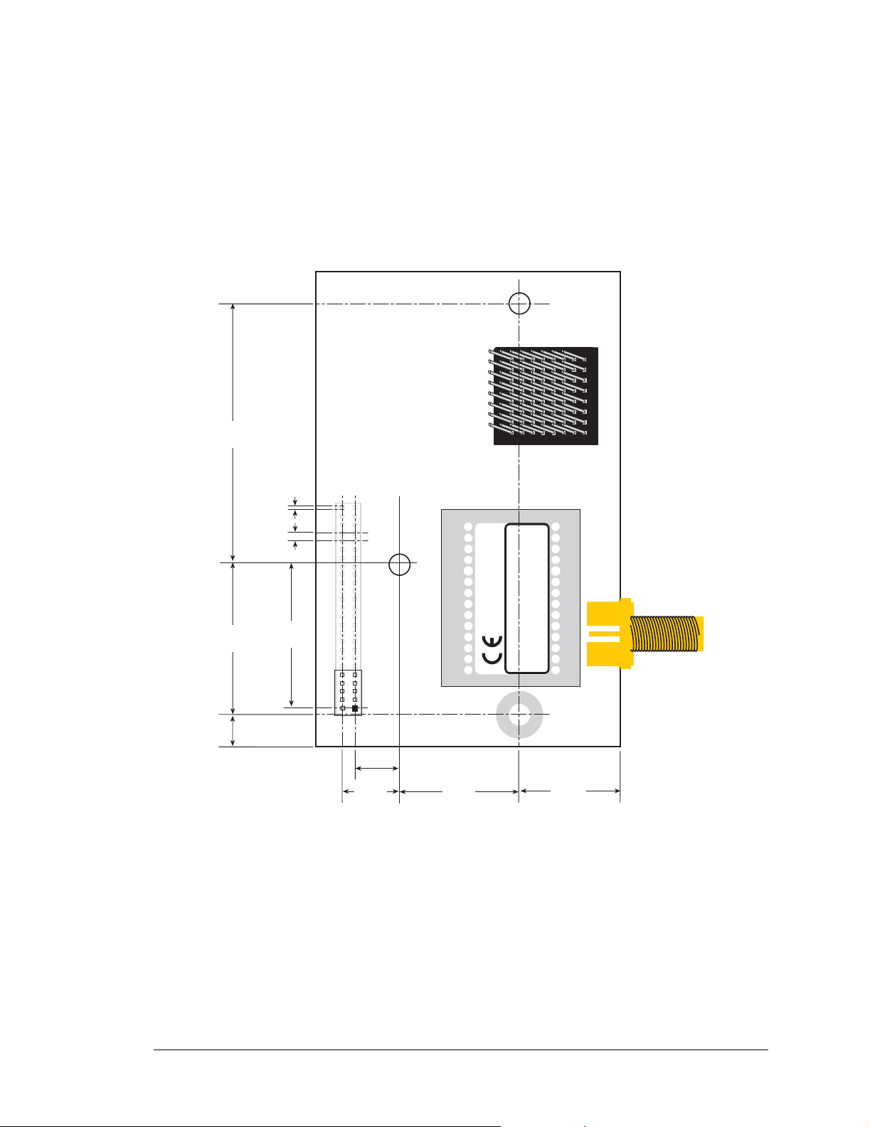
A.1.2 Headers
The RCM5400W uses a header at J1 for physical connection to other boards. J1 is a 2 × 25
SMT header with a 1.27 mm pin spacing. J2, the programming port, is a 2 × 5 header with
a 1.27 mm pin spacing
Figure A-4 shows the layout of another board for the RCM5400W to be plugged into.
These reference design values are relative to one of the mounting holes.
RCM5400W Series
Footprint
1.56
(39)
0.91
(23)
0.016
(0.4)
0.050
0.19
(5)
sq.
(1.27)
0.875
(22.2)
J1
INTERNATIONAL
INTERNATIONAL
®
®
RCM5400W
DIGI
DIGI
RABBIT RCM5400W
J2
0.284
(7.2)
0.334
(8.5)
Figure A-4. User Board Footprint for RCM5400W
0.72
(18)
901-0190
901-0190
0.62
(16)
OEM User’s Manual 83
Page 90

A.2 Rabbit 5000 Microprocessor DC Characteristics
Table A-2. Rabbit 5000 Absolute Maximum Ratings
Symbol Parameter Maximum Rating
V
VDD
Maximum Input Voltage
IH
Maximum Operating Voltage 3.6 V
IO
VDD
+ 0.3 V
IO
(max. 3.6 V)
Stresses beyond those listed in Table A-3 may cause permanent damage. The ratings are
stress ratings only, and functional operation of the Rabbit 5000 chip at these or any other
conditions beyond those indicated in this section is not implied. Exposure to the absolute
maximum rating conditions for extended periods may affect the reliability of the Rabbit
5000 chip.
Table A-3 outlines the DC characteristics for the Rabbit 5000 at 3.3 V over the recommended operating temperature range from TA = –40°C to +85°C, VDDIO = 3.0 V to 3.6 V.
Table A-3. 3.3 Volt DC Characteristics
Symbol Parameter Min Typ Max
VDD
V
V
I/O Ring Supply Voltage, 3.3 V 3.0 V 3.3 V 3.6 V
IO
I/O Core Supply Voltage, 1.8 V 1.65 V 1.8 V 1.90 V
Input High Voltage
IH
Input Low Voltage
IL
2.0 V
0.8 V
V
V
I
Output High Voltage 2.4 V 3.3 V
OH
Output Low Voltage 0.0 V 0.4 V
OL
I/O Ring Current @ 88.4736 MHz,
3.3 V, 25°C
I/O Ring Current @ 29.4912 MHz,
IO
3.3 V, 25°C
I/O Ring Current @ 32.768 kHz,
3.3 V, 25°C
22 mA
12 mA
5 mA
Output drive:
A[19:0], /CS[2:0], /OE[1:0], WE[1:0]
D[7:0]
I
DRIVE
/IOWR, /IORD, /IOBEN
P A[7:0], PB[7:0], PC[7:0], PD[7:0], PH[7:0]
PE[7:0]
All other pins
84 RabbitCore RCM5400W
16 mA
8 mA
16 mA
8 mA
16 mA
8 mA
Page 91

A.3 I/O Buffer Sourcing and Sinking Limit
Unless otherwise specified, the Rabbit I/O buffers are capable of sourcing and sinking
8 mA of current per pin at full AC switching speed. Full AC switching assumes a
100 MHz CPU clock with the clock doubler enabled and capacitive loading on address
and data lines of less than 70 pF per pin. The absolute maximum operating voltage on all
I/O is 3.3 V ±10%.
A.4 Bus Loading
You must pay careful attention to bus loading when designing an interface to the
RCM5400W. This section provides bus loading information for external devices.
Table A-4 lists the capacitance for the various RCM5400W I/O ports.
Table A-4. Capacitance of Rabbit 5000 I/O Ports
Input
I/O Ports
Parallel Ports A to E 12 14
Capacitance
(pF)
Output
Capacitance
(pF)
Table A-5 lists the external capacitive bus loading for the various RCM5400W output
ports. Be sure to add the loads for the devices you are using in your custom system and
verify that they do not exceed the values in Table A-5.
Table A-5. External Capacitive Bus Loading -20°C to +85°C
Output Port
All I/O lines with clock
doubler enabled
Clock Speed
(MHz)
73.73 100
Maximum External
Capacitive Loading (pF)
OEM User’s Manual 85
Page 92

Figure A-5 shows a typical timing diagram for the Rabbit 5000 microprocessor external
I/O read and write cycles.
External I/O Read (no extra wait states)
T1
Tw
T2
CLK
A[15:0]
/CSx
/IOCSx
/IORD
/BUFEN
D[7:0]
CLK
A[15:0]
valid
T
adr
T
CSx
T
IOCSx
T
IORD
T
BUFEN
External I/O Write (no extra wait states)
T1
T
adr
Tw
valid
T2
T
T
IOCSx
T
IORD
T
BUFEN
T
setup
T
CSx
valid
hold
/CSx
T
CSx
T
CSx
/IOCSx
T
IOCSx
T
IOCSx
/IOWR
T
IOWR
T
IOWR
/BUFEN
valid
T
BUFEN
T
DVHZ
T
BUFEN
D[7:0]
T
DHZV
Figure A-5. External I/O Read and Write Cycles—No Extra Wait States
NOTE: /IOCSx can be programmed to be active low (default) or active high.
86 RabbitCore RCM5400W
Page 93

Table A-6 lists the delays in gross memory access time for several values of VDDIO.
Table A-6. Preliminary Data and Clock Delays
Clock to Address
VDD
IO
(V)
3.3 6 8 11 1 2.3 / 2.3 3 / 4.5 4.5 / 9
1.8 18 24 33 3 7 / 6.5 8 / 12 11 / 22
Output Delay
(ns)
30 pF 60 pF 90 pF
Data Setup
Time Delay
(ns)
0.5 ns setting
no dbl / dbl
Spectrum Spreader Delay
Worst-Case
(ns)
1 ns setting
no dbl / dbl
2 ns setting
no dbl / dbl
The measurements are taken at the 50% points under the following conditions.
• T = -20°C to 85°C, V = VDD
±10%
IO
• Internal clock to nonloaded CLK pin delay ≤ 1 ns @ 85°C/3.0 V
The clock to address output delays are similar, and apply to the following delays.
• T
• T
• T
• T
, the clock to address delay
adr
, the clock to memory chip select delay
CSx
, the clock to I/O chip select delay
IOCSx
, the clock to I/O read strobe delay
IORD
• T
• T
The data setup time delays are similar for both T
, the clock to I/O write strobe delay
IOWR
BUFEN
, the clock to I/O buffer enable delay
setup
and T
hold
.
When the spectrum spreader is enabled with the clock doubler, every other clock cycle is
shortened (sometimes lengthened) by a maximum amount given in the table above. The
shortening takes place by shortening the high part of the clock. If the doubler is not
enabled, then every clock is shortened during the low part of the clock period. The maximum shortening for a pair of clocks combined is shown in the table.
Rabbit Semiconductor’s Technical Note TN227, Interfacing External I/O with Rabbit
Microprocessor Designs, which is included with the online documentation, contains sugges-
tions for interfacing I/O devices to the Rabbit 5000 microprocessors.
OEM User’s Manual 87
Page 94

A.5 Jumper Configurations
Figure A-6 shows the header locations used to configure the various RCM5400W options
via jumpers.
RCM5400W
JP5
JP6
L18
2
3
C113
C110
C102
C108
U20
4
C103
C107
C139
901-0190
C104
L19
C105
C106
C134
C115
C121
C118
C114
T1
C119
INTERNATIONAL
®
C135
L22
C120
C136
DIGI
U19
C144
RABBIT RCM5400W
JP4
JP2
JP3
JP1
R19
C111
C112
U18
L20
C116
L21
C117
U21
Figure A-6. Location of RCM5400W Configurable Positions
Table A-7 lists the configuration options.
Table A-7. RCM5400W Jumper Configurations
Header Description Pins Connected
JP1
JP2
JP3
PE6 or SMODE1 Output on J1
pin 38
PE5 or SMODE0 Output on J1
pin 37
PE7 or STATUS Output
on J1 pin 39
JP4 Reserved for future use.
1–2 PE6
2–3 SMODE1
1–2 PE5
2–3 SMODE0
1–2 PE7
2–3 STATUS
1–2 PE0
2–3 A20
Factory
Default
×
×
×
×
88 RabbitCore RCM5400W
Page 95

Table A-7. RCM5400W Jumper Configurations (continued)
Header Description Pins Connected
1–2 ≤ 1MB
JP5 Flash me mory size.
2–3 > 1MB
Control disabled—Wi-Fi power
1–2
supply is always on
JP6 Wi-Fi power supply control.
Control enabled so that the Wi-Fi
2–3
power supply is under
microprocessor control
NOTE: The jumper connections are made using 0 Ω surface-mounted resistors.
Factory
Default
×
×
OEM User’s Manual 89
Page 96

90 RabbitCore RCM5400W
Page 97

APPENDIX B. PROTOTYPING BOARD
Appendix B describes the features and accessories of the Prototyping Board, and explains the use of the Prototyping Board to
demonstrate the RCM5400W and to build prototypes of your
own circuits. The Prototyping Board has pow er-supply connections and also provides some basic I/O peripherals (RS-232,
LEDs, and switches), as well as a prototyping area for more
advanced hardware development.
OEM User’s Manual 91
Page 98

B.1 Introduction
The Prototyping Board included in the Development Kit makes it easy to connect an
RCM5400W module to a power supply and a PC workstation for development. It also provides some basic I/O peripherals (RS-232, LEDs, and switches), as well as a prototyping
area for more advanced hardware development.
For the most basic level of evaluation and development, the Prototyping Board can be
used without modification.
As you progress to more sophisticated experimentation and hardware development,
modifications and additions can be made to the board without modifying the RCM5400W
module.
The Prototyping Board is shown below in Figure B-1, with its main features identified.
Current-
Measurement
Headers
RCM5400W
Module
Connector
RCM5400W
Standoff
Mounting
SMT Prototyping
Area
Power
LED
D1
RX43
RX47
RX97
Power
Input
PWR
R1
J1
DS1
C1
GND
GND
C2
C53
C5
L1
D2
C6
RCM1
U2
JP16
JP6
C18
JP5
C17
JP12
U3
JP4
JP3
JP14
JP8
C16
JP7
JP18
JP9
JP10
C19 C20
R25
C15
R26
Q1
R29
JP11
JP15
JP19
JP21
JP22
JP20
R20
R18
R16
R14
R13
R15
R17
R10
R8R6R4R3R5
R7
C8C7C9
C14
C12
C10
JP24
JP23
RX59
RX57
RX55
RX49
UX33UX31
RX89
UX3
RX61
RX65
UX37 UX42 UX41
RX63
RCM5400W
Module
Extension Header
U1
JP1
/RST_OUT
JP17
C11
R2
C4
C3
J2
+3.3 V
+5 V
GND
JP2
/IORD
+3.3 V
/IOWR
/RST_IN
VBAT
PA0
EXT
PA1
PA2
PA3
PA4
PA5
PA6
PA7
PB0
PB1
PB2
PB3
PB4
PB5
PB6
PB7
PC0
PC1
PC2
Prototyping Area
PC3
PC4
PC5
PC6
PC7
PE0
PE1
PE2
JP13
PE3
PE4
R19
PE5
PE6
R9
PD0
PE7
LN0
PD1
PD2
LN1
LN2
C13
PD4
PD3
LN4
LN3
PD6
PD5
LN6
LN5
PD7
CVT
LN7
VREF
AGND
VREF
LN7IN
J3
CVT
AGND
Analog
I/O
Backup
Battery
BT1
UX49
UX47
GND
Through-Hole
RX75
RX73
AGND
CX25
DS2
JP25
LN5IN
LN3IN
LN6IN
LN4IN
R23
LN1IN
AGND
R12
R11
LN2IN
LN0IN
User
Switches
+5 V, 3.3 V, and
GND Buses
Switch
1
S1
RESET
UX4
CX27
RX77
CX23
DS3
R21
1
R27
RXD TXD
GND
RX81
RX87
RX83
RX67
R22
R24
R28
S3S2
CX41
CX39
RX11
UX45
UX10
CX17
UX12
UX14
RX85
CX29
RX79
UX16
GND
1
GND
GND
Reset
TXC RXC
J4
UX29
UX30
LEDs
RS-232
Header
SMT Prototyping
Area
User
Figure B-1. Prototyping Board
92 RabbitCore RCM5400W
Page 99

B.1.1 Prototyping Board Features
• Power Connection—A a 3-pin header is provided for connection to the power supply.
Note that the 3-pin header is symmetrical, with both outer pins connected to ground and
the center pin connected to the raw V+ input. The cable of the AC adapter provided
with the North American version of the Development Kit is terminated with a header
plug that connects to the 3-pin header in either orientation. The header plug leading to
bare leads provided for overseas customers can be connected to the 3-pin header in
either orientation.
Users providing their own power supply should ensure that it delivers 8–24 V DC at
8 W. The voltage regulators will get warm while in use.
Regulated Power Supply—The raw DC voltage provided at the 3-pin header is
•
routed to a 5 V switching voltage regulator, then to a separate 3.3 V linear regulator.
The regulators provide stable power to the RCM5400W module and the Prototyping
Board.
• Power LED—The power LED lights whenever power is connected to the Prototyping
Board.
• Reset Switch—A momentary-contact, normally open switch is connected directly to the
RCM5400W’ s / RESET_IN pin. Pressing the switch forces a hardware reset of the system.
• I/O Switches and LEDs—Two momentary-contact, normally open switches are connected to the PB4 and PB5 pins of the RCM5400W module and may be read as inputs
by sample applications.
Two LEDs are connected to the PB2 and PB3 pins of the RCM5400W module, and
may be driven as output indicators by sample applications.
• Prototyping Area—A generous prototyping area has been provided for the installation
of through-hole components. +3.3 V, +5 V, and Ground buses run around the edge of
this area. Several areas for surface-mount devices are also available. (Note that there
are SMT device pads on both top and bottom of the Prototyping Board.) Each SMT pad
is connected to a hole designed to accept a 30 AWG solid wire.
• Module Extension Header—The complete pin set of the RCM5400W module is
duplicated at header J2. Developers can solder wires directly into the appropriate holes,
or, for more flexible development, a 2 × 25 header strip with a 0.1" pitch can be soldered into place. See Figure B-4 for the header pinouts.
NOTE: The same Prototyping Board can be used for several series of RabbitCore mod-
ules, an d so the sig nals at J2 depend on the si gnals ava ilabl e on the speci fic Rabb itCore
module.
OEM User’s Manual 93
Page 100

• Analog Inputs Header—The analog signals from a RabbitCore module are presented
at header J3 on the Prototyping Board. These analog signals are connected via attenuator/
filter circuits on the Prototyping Board to the corresponding analog inputs on the RabbitCore module.
NOTE: No analog signals are available on the Prototyping Board with the RCM5400W
RabbitCore module inst alled s ince no a nalog si gnals ar e avail able on t he RCM5400W’s
header J1.
• RS-232—Two 3-wire or one 5-wire RS-232 serial ports are available on the Prototyping Board at header J4. A 10-pin 0.1" pitch header strip installed at J4 allows you to
connect a ribbon cable that leads to a standard DE-9 serial connector.
• Current Measurement Option—You may cut the trace below header JP1 on the
bottom side of the Prototyping Board and install a 1 × 2 header strip from the Development Kit to allow you to use an ammeter across the pins to measure the current drawn
from the +5 V supply. Sim ilarly, you may cut the trace below header JP2 on the bottom
side of the Prototyping Board and install a 1 × 2 header strip from the Development Kit
to allow you to use an ammeter across the pins to measure the current drawn from the
+3.3 V supply.
• Backup Battery—A 2032 lithium-ion battery rated at 3.0 V, 220 mA·h, provides
battery backup for the RCM5400W data SRAM and real-time clock.
94 RabbitCore RCM5400W
 Loading...