

Page 1

RabbitCore RCM3700
with Ethernet, Serial Flash, and Enhanced Software
C-Programmable Core Module
User’s Manual
019–0136_L
Page 2

RabbitCore RCM3700 User’s Manual
Part Number 019-0136_L • Printed in U.S.A.
©2003–2010 Digi International Inc. • All right s reserved .
Digi International reserves the right to make changes and
improvements to its products without providing notice.
T rademarks
Rabbit, RabbitCore, and Dynamic C are registered trademarks of Digi International Inc.
Rabbit 3000 is a trademark of Digi International I nc.
The latest revision of this manual is available on the Rabbit Web site, www.rabbit.com,
for free, unregistered download.
Rabbit Semiconductor Inc.
www .rabbi t.com
RabbitCore RCM3700
Page 3

TABLE OF CONTENTS
Chapter 1. Introduction 4
1.1 RCM3700 Features................................. ..............................................................................................4
1.2 Advantages of the RCM3700 ...............................................................................................................6
1.3 Development and Evaluation Tools......................................................................................................7
1.3.1 Development Kit...........................................................................................................................7
1.3.2 Software........................................................................................................................................8
1.3.3 Application Kits............................................................................................................................8
1.3.4 Online Documentation............................................. ................................................ .....................8
Chapter 2. Getting Started 9
2.1 Step 1 — Install Dynamic C...................................... ...........................................................................9
2.2 Hardware Connections........................................................................................................................10
2.2.1 Step 1 — Attach Module to Prototyping Board..........................................................................10
2.2.2 Step 2 — Connect Programming Cable......................................................................................11
2.2.3 Step 3 — Connect Power............................................................................................................12
2.2.3.1 Overseas Development Kits................................ ... ................................................ .. .......... 12
2.3 Starting Dynamic C ............................................................................................................................13
2.4 Run a Sample Program.......................................................................................................................13
2.4.1 Troubleshooting ..........................................................................................................................13
2.5 Where Do I Go From Here? ...............................................................................................................14
2.5.1 Technical Support.......................................................................................................................14
Chapter 3. Running Sample Programs 15
3.1 Introduction.........................................................................................................................................15
3.2 Sample Programs................................................................................................................................17
3.2.1 Use of Serial Flash......................................................................................................................19
3.2.2 Serial Communication.................................................................................................................19
3.2.3 A/D Converter Inputs..................................................................................................................22
Chapter 4. Hardware Reference 25
4.1 RCM3700 Digital Inputs and Outputs................................................................................................26
4.1.1 Memory I/O Interface .................................................................................................................30
4.1.2 Other Inputs and Outputs............................................................................................... .............30
4.2 Serial Communication ........................................................................................................................31
4.2.1 Serial Ports..................................................................................................................................31
4.2.2 Ethernet Port ................................................................................... ............................................32
4.2.3 Serial Programming Port.............................................................................................................33
4.3 Serial Programming Cable..................................................................................................................34
4.3.1 Changing Between Program Mode and Run Mode....................................................................34
4.3.2 Standalone Operation of the RCM3700......................................................................................35
4.4 Other Hardware............................................... ....................................................................................36
4.4.1 Clock Doubler.............................................................................................................................36
4.4.2 Spectrum Spreader........................................... .. .........................................................................36
RabbitCore RCM3700 User’s Manual 1
Page 4

4.5 Memory...............................................................................................................................................37
4.5.1 SRAM .........................................................................................................................................37
4.5.2 Flash EPROM.............................................................................................................................37
4.5.3 Serial Flash..................................................................................................................................37
4.5.4 Dynamic C BIOS Source Files ...................................................................................................37
Chapter 5. Software Reference 38
5.1 More About Dynamic C .....................................................................................................................38
5.2 Dynamic C Functions .........................................................................................................................40
5.2.1 Board Initialization .....................................................................................................................41
5.2.2 Analog Inputs.............................................................. ................................................................42
5.2.3 Digital I/O...................................................................................................................................58
5.2.4 Serial Communication Drivers....................................................................................................59
5.2.5 Serial Flash..................................................................................................................................59
5.2.6 TCP/IP Drivers............................................................................................................................59
5.3 Upgrading Dynamic C.................................... ....................................................................................60
5.3.1 Extras ..........................................................................................................................................60
5.3.1.1 Featured Application Kit.................................................................................................... 60
Chapter 6. Using the TCP/IP Features 61
6.1 TCP/IP Connections ...........................................................................................................................61
6.2 TCP/IP Primer on IP Addresses..........................................................................................................63
6.2.1 IP Addresses Explained ..............................................................................................................65
6.2.2 How IP Addresses are Used........................................................................................................66
6.2.3 Dynamically Assigned Internet Addresses .................................................................................67
6.3 Placing Your Device on the Network.................................................................................................68
6.4 Running TCP/IP Sample Programs ....................................................................................................69
6.4.1 How to Set IP Addresses in the Sample Programs .....................................................................70
6.4.2 How to Set Up your Computer for Direct Connect ....................................................................71
6.5 Run the PINGME.C Sample Program................................................................................................72
6.6 Running Additional Sample Programs With Direct Connect.............................................................72
6.6.1 RabbitWeb Sample Programs.....................................................................................................73
6.6.2 Secure Sockets Layer (SSL) Sample Programs ..........................................................................74
6.6.3 Dynamic C FAT File System, RabbitWeb, and SSL Modules...................................................74
6.7 Where Do I Go From Here? ...............................................................................................................76
Appendix A. RCM3700 Specifications 77
A.1 Electrical and Mechanical Characteristics.........................................................................................78
A.1.1 Headers.......................................................................................................................................81
A.2 Bus Loading............................... ................................................ ........................................................82
A.3 Rabbit 3000 DC Characteristics.........................................................................................................85
A.4 I/O Buffer Sourcing and Sinking Limit .............................................................................................86
A.5 Conformal Coating.............................................................................................................................87
A.6 Jumper Configurations.................................................... ...................................................................88
Appendix B. Prototyping Board 90
B.1 RCM3700 Prototyping Board ............................................................. ...............................................91
B.1.1 Features .................................... ..................................................................................................92
B.1.2 Mechanical Dimensions and Layout..........................................................................................94
B.1.3 Power Supply ...................................... .......................................................................................95
B.1.4 Using the RCM3700 Prototyping Board....................................................................................96
B.1.4.1 Adding Other Components....................................................... ......................................... 97
B.1.5 Analog Features....................................................... ................................................ .. .................98
B.1.5.1 A/D Converter Inputs ........................................................................................................ 98
B.1.5.2 Thermistor Input.............................................................................................................. 100
B.1.5.3 Other A/D Converter Features......................................................................................... 101
B.1.5.4 A/D Converter Calibration .............................................................................................. 102
RabbitCore RCM3700 User’s Manual 2
Page 5

B.1.6 Serial Communication.............. ................................................ ................................................103
B.1.6.1 RS-232...................... ....................................................................................................... 104
B.1.6.2 RS-485...................... ....................................................................................................... 105
B.1.7 Other Prototyping Board Modules ...........................................................................................107
B.1.8 Jumper Configurations .............................................................................................................108
B.1.9 Use of Rabbit 3000 Parallel Ports ............................................................................................110
B.2 RCM3720 Prototyping Board ............................................................. .............................................112
B.2.1 Features .................................... ................................................................................................113
B.2.2 Mechanical Dimensions and Layout........................................................................................114
B.2.3 Power Supply ...................................... .....................................................................................115
B.2.4 Using the RCM3720 Prototyping Board..................................................................................116
B.2.4.1 Prototyping Area...................................... ........................................................................ 118
B.2.5 Serial Communication.............. ................................................ ................................................119
B.2.6 Use of Rabbit 3000 Parallel Ports ............................................................................................121
Appendix C. LCD/Keypad Module 123
C.1 Specifications...................................................................................................................................123
C.2 Contrast Adjustments for All Boards................................................................... ............................125
C.3 Keypad Labeling..............................................................................................................................126
C.4 Header Pinouts.................................................................................................................................127
C.4.1 I/O Address Assignments.........................................................................................................127
C.5 Install Connectors on Prototyping Board..................... ....................................................................128
C.6 Mounting LCD/Keypad Module on the Prototyping Board ............................................................129
C.7 Bezel-Mount Installation..................................................................................................................130
C.7.1 Connect the LCD/Keypad Module to Your Prototyping Board...............................................132
C.8 Sample Programs .............................................................................................................................133
C.9 LCD/Keypad Module Function Calls .......................... ................................................ ....................134
C.9.1 LCD/Keypad Module Initialization............................................. .............................................134
C.9.2 LEDs.................................................................................................... .....................................134
C.9.3 LCD Display.............................................................................................................................135
C.9.4 Keypad......................................... ................................................ .............................................155
Appendix D. Power Supply 158
D.1 Power Supplies.................................................................................................................................158
D.1.1 Battery Backup................................................................................. ........................................159
D.1.2 Battery-Backup Circuit ............................................................................................................160
D.1.3 Reset Generator........................................................................................................................160
Appendix E. Secure Embedded Web Application Kit 161
E.1 Sample Programs.................................................................................................. ............................162
E.2 Module Documentation....................................................................................................................162
Index 163
Schematics 167
RabbitCore RCM3700 User’s Manual 3
Page 6

1. INTRODUCTION
The RCM3700 is a compact module that incorporates the latest
®
revision of the powerful Rabbit
memory, onboard serial flash, static RAM, and digital I/O ports.
Throughout this manual, the term RCM3700 refers to the complete series of RCM3700
RabbitCore modules unless other production models are referred to specifically.
The RCM3700 has a Rabbit 3000 microprocessor operating at 22.1 MHz, static RAM,
flash memory , two clocks (main oscillator and real-time clock), and the circuitry necessary
for reset and management of battery backup of the Rabbit 3000’s internal real-time clock
and the static RAM. One 40-pin header brings out the Rabbit 3000 I/O bus lines, parallel
ports, and serial ports.
The RCM3700 receives its +5 V power from the customer-supplied motherboard on
which it is mounted. The RCM3700 can interface with all kinds of CMOS-compatible
digital devices through the motherboard.
3000 microprocessor, flash
The Development Kit and the Ethernet Connection Kit have what you need to design your
own microprocessor-based system: a complete Dynamic C software development system
with optional modules and a Prototyping Board that acts as a motherboard to allow you to
evaluate the RCM3700 and to prototype circuits that interface to the RCM3700 module.
1.1 RCM3700 Features
• Small size: 1.20" x 2.95" x 0.98"
(30 mm x 75 mm x 25 mm)
• Microprocessor: latest revision of Rabbit 3000 running
Secure Sockets Layer (SSL) module for added security
• 33 parallel 5 V tolerant I/O lines: 31 configurable for I/O, 2 fixed outputs
• External reset I/O
• Alternate I/O bus can be configured for 8 data lines and 5 address lines (shared with
parallel I/O lines), I/O read/write
• Ten 8-bit timers (six cascadable) and one 10-bit timer with two match registers
• 512K flash memory and 512K SRAM (options for 256K flash memory and 128K SRAM)
at 22.1 MHz supports Dynamic C
RabbitCore RCM3700 User’s Manual 4
Page 7

• 1 Mbyte serial flash memory , which is required to run the optional Dynamic C FAT file
system
• Real-time clock
• Watchdog supervisor
• Provision for customer-supplied backup battery via connections on header J1
• 10-bit free-running PWM counter and four pulse-width registers
• Two-channel Input Capture can be used to time input signals from various port pins
• Two-channel Quadrature Decoder accepts inputs from external incremental encoder
modules
•
Four available 3.3 V CMOS-compatible serial ports: maximum asynchronous baud rate
of 2.76 Mbps
. Three ports are configurable as a clocked serial port (SPI), and one port
is configurable as an HDLC serial port. Shared connections to the Rabbit microprocessor make a second HDLC serial port available at the expense of two of the SPI configurable ports, giving you two HDLC ports and one asynchronous/SPI serial port.
• Supports 1.15 Mbps IrDA transceiver
There are three RCM3700 production models. Table 1 below summarizes their main
features.
Table 1. RCM3700 Features
Feature RCM3700 RCM3710 RCM3720
Microprocessor
Flash Memory 512K 256K 512K
SRAM 512K128K256K
Serial Flash Memory 1 Mbyte
4 shared high-speed, 3.3 V CMOS-compatible ports:
all 4 are configurable as asynchronous serial ports;
Serial Ports
3 are configurable as a clocked serial port (SPI) and 1 is configurable as
an HDLC serial port;
option for second HDLC serial port at the expense of 2 clocked serial
ports (SPI)
Rabbit 3000
®
running at 22.1 MHz
The RCM3700 is programmed over a standard PC serial port through a programming cable
supplied with the Development Kit or the Ethernet Connection Kit, and can also be programed through a USB port with an RS-232/USB converter or over an Ethernet with the
RabbitLink (both available from Rabbit).
Mounting holes were introduced on opposite corners of the RCM3700 in 2009.
Appendix A provides detailed specifications for the RCM3700.
RabbitCore RCM3700 User’s Manual 5
Page 8

1.2 Advantages of the RCM3700
• Fast time to market using a fully engineered, “ready-to-run/ready-to-program” microprocessor core.
• Competitive pricing when compared with the alternative of purchasing and assembling
individual components.
• Easy C-language program development and debugging
• Rabbit Field Utility to download compiled Dynamic C .bin files, and cloning board
options for rapid production loading of programs.
• Generous memory size allows large programs with tens of thousands of lines of code,
and substantial data storage.
• Integrated Ethernet port for network connectivity, with royalty-free TCP/IP software.
• Ideal for network-enabling security and access systems, home automation, HVAC
systems, and industrial controls
RabbitCore RCM3700 User’s Manual 6
Page 9

1.3 Development and Evaluation Tools
Rabbit and Dynamic C are registered trademarks of Digi International Inc.
RabbitCore RCM3700
The RCM3700 RabbitCore module features built-in built-in Ethernet and onboard mass storage (serial
flash) in addition to 33 I/O lines. These Getting Started instructions included with the Development Kit
will help you get your RCM3700 up and running so that you can run the sample programs to explore its
capabilities and develop your own applications.
Development Kit Contents
The RCM3700 Development Kit contains the following items:
t
RCM3700 module.
t
Prototyping Board.
t
Universal AC adapter, 12 V DC, 1 A (includes Canada/Japan/U.S., Australia/N.Z., U.K., and European
style plugs).
t
Programming cable with 10-pin header and DB9 connections, and integrated level-matching circuitry.
t
Cable kits to access RS-485 and analog input connectors on Prototyping Board.
t
Dynamic C CD-ROM, with complete product documentation on disk.
t
Getting Started instructions.
t
Accessory parts for use on the Prototyping Board.
t
Rabbit 3000 Processor Easy Reference poster.
t
Registration card.
Visit our online Rabbit store at www.rabbit.com/store/ for the latest information on peripherals and accessories that are available for the RCM3700 RabbitCore modules.
Step 1 — Install Dynamic C
®
Before doing any development, you must install Dynamic C. Insert the CD from the Development Kit in
your PC’s CD-ROM drive. If the installation does not auto-start, run the setup .exe program in the root
directory of the Dynamic C CD. Install any Dynamic C modules after you install Dynamic C
.
1.3.1 Development Kit
The Development Kit contains the hardware and software needed to use the RCM3700.
• RCM3700 module.
• RCM3700 Prototyping Board.
• Universal AC adapter, 12 V DC, 1 A (includes Canada/Japan/U.S., Australia/N.Z.,
U.K., and European style plugs).
• Programming cable with 10-pin header and DE9 connections, and integrated levelmatching circuitry.
• Cable kits to access RS-485 and analog input connectors on Prototyping Board.
• Dynamic C CD-ROM, with complete product documentation on disk.
• Getting Started instructions.
• Accessory parts for use on the Prototyping Board.
• Rabbit 3000 Processor Easy Reference poster.
• Registration card.
RabbitCore RCM3700 User’s Manual 7
Figure 1. RCM3700 Development Kit
Page 10

1.3.2 Software
The RCM3700 is programmed using version 8.11 or later of Dynamic C. Dynamic C v . 9.60
includes the popular µC/OS-II real-time operating system, point-to-point protocol (PPP),
FAT file system, RabbitWeb, and other select libraries that were previously sold as indidual Dynamic C modules.
Rabbit also offers for purchase the Rabbit Embedded Security Pack featuring the Secure
Sockets Layer (SSL) and a specific Advanced Encryption Standard (AES) library. In addition to the Web-based technical support included at no extra charge, a one-year telephonebased technical support subscription is also available for purchase. Visit our Web site at
www.rabbit.com for further information and complete documentation, or contact your
Rabbit sales representative or authorized distributor.
1.3.3 Application Kits
Rabbit also has application kits featuring the RCM3700 to provide the exact software and
other tools that will enable to tailor your RCM3700 for specific applications.
• Secure Embedded W eb Application Kit (Ra bbit Part No. 101-0898)—comes with three
CD-ROMs that have the Dynamic C RabbitWeb, FAT File System, and Secure Sockets
Layer (SSL) modules, and includes Dynamic C 8.51 or a later version and an
RCM3700. This enhanced software bundle facilitates the rapid development of secure
Web browser interfaces for embedded system control. Appendix E provides additional
information about the Secure Embedded Web Application Kit.
• Ethernet Connection Kit (Rabbit Part No. 101-0964)—comes with one CD-ROM that
includes Dynamic C 9.01 or a later version, an RCM3720 module, and an RCM3720
Prototyping Board. This kit is intended to demonstrate and help you develop Ethernetbased applications.
V isit our Web site at www.rabbit.com or contact your Rabbit sales representative or authorized distributor for further information.
1.3.4 Online Documentation
The online documentation is installed along with Dynamic C, and an icon for the documentation menu is placed on the workstation’ s desktop. Double-click this icon to reach the
menu. If the icon is missing, use your browser to find and load default.htm in the docs
folder, found in the Dynamic C installation folder.
Each Dynamic C module has complete documentation available with the online documentation described above.
The latest versions of all documents are always available for free, unregistered download
from our Web sites as well.
RabbitCore RCM3700 User’s Manual 8
Page 11

2. GETTING STARTED
This chapter describes the RCM3700 hardware in more detail, and
explains how to set up and use the accompanying Prototyping Board.
NOTE: It is assumed that you have the RCM3700 Development Kit. If you purchased an
RCM3700 module by itself, you will have to adapt the information in this chapter and
elsewhere to your test and development setup.
2.1 Step 1 — Install Dynamic C
T o develop and debug programs for the RCM3700 (and for all other Rabbit hardware), you
must install and use Dynamic C.
If you have not yet installed Dynamic C version 8.11 (or a later version), do so now by
inserting the Dynamic C CD from the RCM3700 Development Kit in your PC’s CD-ROM
drive. If autorun is enabled, the CD installation will begin automatically.
If autorun is disabled or the installation otherwise does not start, use the Windows
Start | Run menu or Windows Disk Explorer to launch setup.exe from the root folder
of the CD-ROM.
The installation program will guide you through the installation process. Most steps of the
process are self-explanatory.
Dynamic C uses a COM (serial) port to communicate with the target development system.
The installation allows you to choose the COM port that will be used. The default selection is COM1. You may select any available port for Dynamic C’s use. If you are not certain which port is available, select COM1. This selection can be changed later within
Dynamic C.
NOTE: The installation utility does not check the selected COM port in any way. Speci-
fying a port in use by another device (mouse, modem, etc.) may lead to a message such
"could not open serial port" when Dynamic C is started.
as
Once your installation is complete, you will have up to three icons on your PC desktop.
One icon is for Dynamic C, one opens the documentation menu, and the third is for the
Rabbit Field Utility, a tool used to download precompiled software to a target system.
If you have purchased any of the optional Dynamic C modules, install them after installing
Dynamic C. The modules may be installed in any order. You must install the modules in
the same directory where Dynamic C was installed.
RabbitCore RCM3700 User’s Manual 9
Page 12

2.2 Hardware Connections
+V
/RESET
LDE0
LED2
LED4
LED6
GND
+BKLT
/CS
LED1
LED3
LED5
GND
GND
A2
A1
D1D3D5
D7
GND
A3A1D0D2D4D6GND
+BKLT
/CS
LED1
LED3
LED5
GND
GND
A2
A0
D1D3D5
D7
L2
C1
C2
IR1
R1
R2
R3
R4
Rx
Tx
R5
R6
C3
R9
R7
R8
JP1
J1
+485
GND
485
JP2
R12
R11
U3
C4
C7
C8
C10
R13
C11
U4
C5
C6
C9
J2
GND
/IORD
PB5
PB3
PA0
PA6
PB0
/RES
+5V
PF4
PF6
PC1/PG2
PC0_TXD
PE5
PE1
PG7_RXE
PD4
VBAT
PA4 PA2
/IOWR
PE7
PB4
PB2
PA1
PA3
PA5
PA7
PB7
PF0
PF1
PF5
PF7
PE4
PE0
PD5
PG6
TXE
PC2
TXC
PC3/
PG3
GND
RXC TXC RXE
GND
NC
U1
C12
C13
C15
C14
L1
C17
U2
C18
U6
R14
D1
C19
D2
J4
DCIN
+3.3V
GND
+5V
+5V
GND
+3.3V
LCD1JB
LCD1JC
LCD1JA
U5
C16
R15
BT1
GND
TXD
RXD
TXE
GND
TCM_SMT_SOCKET
+5V
VBAT
PD5
/IORD
PG6_TXE
PE0
PE4
PE7
PC2_TXC
PC0_TXD
PF6
PF4
PB5
PB3
PB0
PF1
PA1
PA3
PA5
PA7
J5
GND
R16
GND
/RES
PD4
/IOWR
PE1
PE5
PC3/PG3
PF7
PF5
PB7
PB4
PB2
PF0
PA0
PA2
PA4
PA6
PG7
RXE
PC1/
PG2
C22
C26
R21
R18
C20
R19
C21
R20
R22
JP4
1
2
RP1
CX1 CX2
CX3
CX4
CX5
CX6
CX7
CX8
CX9
CX10CX11
UX2
UX1
U8
R23
C24 C25
C23
U7
C27
R25
R24
C28
R26
R27
R28
R29
JP8
R30 R31 R32
R33
R34
R35
R36
C35
R43
C29
J7
THERMISTOR
R37
J8
VREF
AGND
R44
THERM_IN
AIN
06050403020100
AIN
AGND
R38
C30
C31
C32
C33
C34
R39 R40
R41 R42
R48
DS1
DS2
R45
R49
R46
DS3
R47
S3
S2S1
CONVERT
JP5
JP6
JP7
NC
NCNCNC
NC
NC
+V
/RSTETLED0
LED2
LED4
LED6
GNDA3A1D0D2D4D6
RCM36/37XX SERIES
PROTOTYPING BOARD
RESET
R24
R2
C18
C34
RP1
RP2
R18
R36
C35
C19
C26
C27
C28
R15
R16
C36
C39
R13
U1
C25
JP1
C7
JP3
J2
C33
C32
C30
C31
C15
C17
C20
C38
C41
U4
R6
R11
C37
R4 R5
U5
C29
JP2
Y1
C40
C10
Q1
R7
C49
L2
L1
C14
C12
C22
U8
C23
Y3
C57
R31
C58
R29
DS2
R32
R30
DS1
J3
R34
C16
R28
T1
C24
C21
D1
U6
C53
R26
U3
R33
C8
U11
L4
L3
C54 C55
L6
R27
TCM_SMT_SOCKET
Align shaded
corners
RCM3700
There are three steps to connecting the Prototyping Board for use with Dynamic C and the
sample programs:
1. Attach the RCM3700 module to the Prototyping Board.
2. Connect the programming cable between the RCM3700 and the COM port on the
workstation PC.
3. Connect the power supply to the Prototyping Board.
The connections are shown for the RCM3700 Prototyping Board, and are similar for the
RCM3720 Prototyping Board.
2.2.1 Step 1 — Attach Module to Prototyping Board
Turn the RCM3700 module so that the Ethernet jack is on the left as shown in Figure 2
below. Insert the module’s J1 header into the TCM_SMT_SOCKET socket on the Prototyping Board. The shaded corner notch at the bottom right corner of the RCM3700 module
should face the same direction as the corresponding notch below it on the Prototyping
Board.
NOTE: It is important that you line up the pins on header J1 of the RCM3700 module
Press the module’s pins firmly into the Prototyping Board headers.
RabbitCore RCM3700 User’s Manual 10
exactly with the corresponding pins of the TCM_SMT_SOCKET socket on the Prototyping Board. The header pins may become bent or damaged if the pin alignment is offset, and the module will not work. Permanent electrical damage to the module may also
result if a misaligned module is powered up.
Figure 2. Install the RCM3700 Series on the Prototyping Board
Page 13

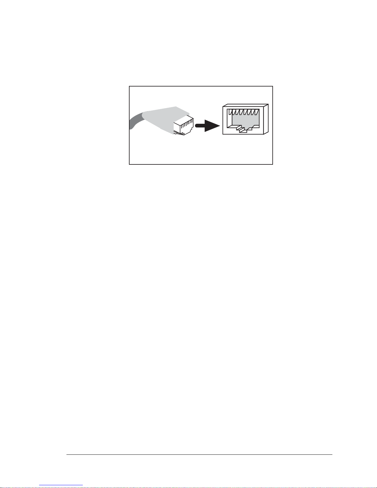
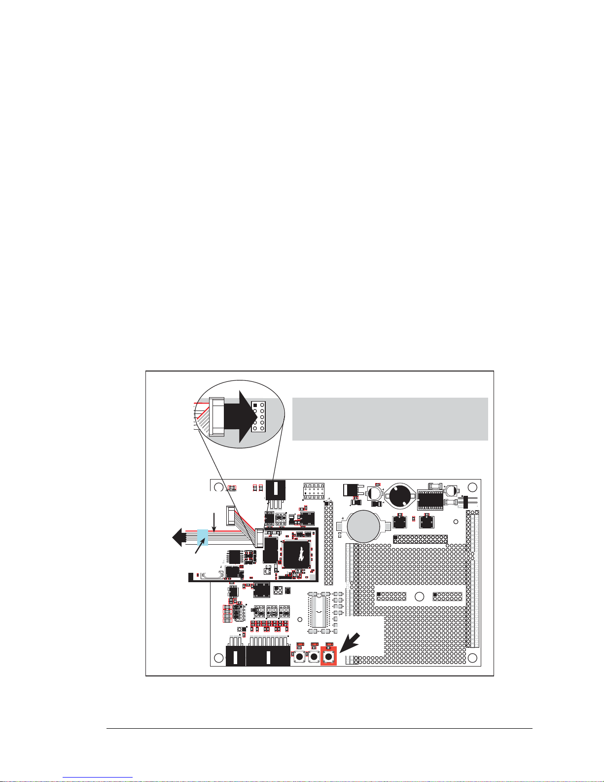
2.2.2 Step 2 — Connect Programming Cable
The programming cable connects the RCM3700 to the PC running Dynamic C to download programs and to monitor the RCM3700 module during debugging.
Connect the 10-pin connector of the programming cable labeled PROG to header J2 on
the RCM3700 as shown in Figure 3. Be sure to orient the marked (usually red) edge of the
cable towards pin 1 of the connector . (Do not use the DIAG connector, which is used for a
normal serial connection.)
Figure 3. Connect Programming Cable and Power Supply
NOTE: Never disconnect the programming cable by pulling on the ribbon cable.
Carefully pull on the connector to remove it from the header.
NOTE: Be sure to use the programming cable (part number 101-0542) supplied with this
Development Kit—the programming cable has blue shrink wrap around the RS-232 converter section located in the middle of the cable. The simplified programming cable and
adapter board that are supplied with the Ethernet Connection Kit may also be used as
shown in the inset diagram above. Programming cables from other Rabbit kits are not
designed to work with RCM3700 modules.
Connect the other end of the programming cable to a COM port on your PC.
NOTE: Some PCs now come equipped only with a USB port. It may be possible to use
an RS-232/USB converter (Part No. 20-151-0178) with the programming cables mentioned above. Note that not all RS-232/USB converters work with Dynamic C.
RabbitCore RCM3700 User’s Manual 11
Page 14

2.2.3 Step 3 — Connect Power
When all other connections have been made, you can connect power to the Prototyping
Board.
First, prepare the AC adapter for the country where it will be used by selecting the plug.
The RCM3700 Development Kit presently includes Canada/Japan/U.S., Australia/N.Z.,
U.K., and European style plugs. Snap in the top of the plug assembly into the slot at the
top of the AC adapter as shown in Figure 3, then press down on the spring-loaded clip
below the plug assembly to allow the plug assembly to click into place.
Connect the AC adapter to 3-pin header J4 on the Prototyping Board as shown in Figure 3.
The connector may be attached either way as long as it is not offset to one side.
Plug in the AC adapter. The LED above the RESET button on the Prototyping Board
should light up. The RCM3700 and the Prototyping Board are now ready to be used.
NOTE: A RESET button is provided on th e Prototyping Bo ard to allow a hardware reset
without disconnecting power.
To power down the Prototyping Board, unplug the power connector from J4. You should
disconnect power before making any circuit adjustments in the prototyping area, changing
any connections to the board, or removing the RCM3700 from the Prototyping Board.
2.2.3.1 Overseas Development Kits
Development kits sold outside North America before 2009 included a header connector
that could be connected to 3-pin header J4 on the Prototyping Board. The connector could
be attached either way as long as it was not offset to one side. The red and black wires
from the connector could then be connected to the positive and negative connections on
your power supply. The power supply should deliver 7.5 V–30 V DC at 500 mA.
RabbitCore RCM3700 User’s Manual 12
Page 15

2.3 Starting Dynamic C
Once the RCM3700 is connected as described in the preceding pages, start Dynamic C by
double-clicking on the Dynamic C icon on your desktop or in your Start menu.
If you are using a USB port to connect your computer to the RCM3700, choose Options >
Project Options
and select “Use USB to Serial Converter.” You may have to determine
which COM port was assigned to the RS-232/USB converter. Click OK.
2.4 Run a Sample Program
Use the File menu to open the sample program PONG.C, which is in the Dynamic C
SAMPLES folder. Press function key F9 to compile and run the program. The STDIO
window will open on your PC and will display a small square bouncing around in a box.
This program shows that the CPU is working.
2.4.1 Troubleshooting
If Dynamic C cannot find the target system (error message "No Rabbit Processor
Detected."
• Check that the RCM3700 is powered correctly — the red power lamp on the Prototyping
Board should be lit when the RCM3700 is mounted on the Prototyping Board and the AC
adapter is plugged in
):
.
• Check both ends of the programming cable to ensure that they are firmly plugged into
the PC and the PROG connector, not the DIAG connector, is plugged in to the programming port on the RCM3700 with the marked (colored) edge of the programming cable
towards pin 1 of the programming header.
• Ensure that the RCM3700 module is firmly and correctly installed in its connectors on
the Prototyping Board.
• Dynamic C uses the COM port specified during installation. Select a different COM
port within Dynamic C. From the
Communications. Select another COM port from the list, then click OK. Press
<Ctrl-Y> to force Dynamic C to recompile the BIOS. If Dynamic C still reports it is
Options menu, select Project Options, then select
unable to locate the target system, repeat the above steps until you locate the COM port
used by the programming cable.
RabbitCore RCM3700 User’s Manual 13
Page 16

If Dynamic C appears to compile the BIOS successfully, but you then receive a communication error message when you compile and load the sample program, it is possible that
your PC cannot handle the higher program-loading baud rate. Try changing the maximum
download rate to a slower baud rate as follows.
• Locate the Serial Options dialog in the Dynamic C Options > Project Options >
Communications menu. Select a slower Max download baud rate.
If a program compiles and loads, but then loses target communication before you can
begin debugging, it is possible that your PC cannot handle the default debugging baud
rate. Try lowering the debugging baud rate as follows.
• Locate the Serial Options dialog in the Dynamic C Options > Project Options >
Communications menu. Choose a lower debug baud rate.
2.5 Where Do I Go From Here?
If the sample program ran fine, you are now ready to go on to other sample programs and to
develop your own applications. The source code for the sample programs
you to modify them for your own use. The RCM3700 User’s Manual also provides
complete hardware reference information and describes the software function calls for the
RCM3700, the Prototyping Board, and the optional LCD/keypad module.
For advanced development topics, refer to the Dynamic C User’s Manual, also in the
online documentation set.
is provided to allow
2.5.1 Technical Support
NOTE: If you purchased your RCM3700 through a distributor or through a Rabbit partner,
contact the distributor or partner first for technical support.
If there are any problems at this point:
• Use the Dynamic C Help menu to get further assistance with Dynamic C.
• Check the Rabbit Technical Bulletin Board and forums at www.rabbit.com/support/bb/
and at www.rabbit.com/forums/.
• Use the Technical Support e-mail form at www.rabbit.com/support/.
RabbitCore RCM3700 User’s Manual 14
Page 17

3. RUNNING SAMPLE PROGRAMS
To develop and debug programs for the RCM3700 (and for all
other Rabbit hardware), you must install and use Dynamic C.
3.1 Introduction
To help familiarize you with the RCM3700 modules, Dynamic C includes several sample
programs. Loading, executing and studying these programs will give you a solid hands-on
overview of the RCM3700’s capabilities, as well as a quick start with Dynamic C as an
application development tool.
NOTE: The sample programs assume that you have at least an elementary grasp of the C
programming language. If you do not, see the introductory pages of the Dynamic C
User’s Manual for a suggested reading list.
In order to run the sample programs discussed in this chapter and elsewhere in this manual,
1. Your RCM3700 must be plugged in to the Prototyping Board as described in Chapter 2,
“Getting Started.”
2. Dynamic C must be installed and running on your PC.
3. The programming cable must connect the programming header (J2) on the RCM3700
to your PC.
4. Power must be applied to the RCM3700 through the Prototyping Board.
Refer to Chapter 2, “Getting Started,” if you need further information on these steps.
To run a sample program, open it with the File menu, then compile and run it by pressing
F9. The RCM3700 must be connected to a PC using the programming cable.
Complete information on Dynamic C is provided in the Dynamic C User’s Manual.
RabbitCore RCM3700 User’s Manual 15
Page 18

The default I/O configuration in the sample programs is based on the RabbitCore module
detected during compile time:
• Any RCM3700 RabbitCore module (except the RCM3720) will have its I/O ports configured for an RCM3700 Prototyping Board.
• An RCM3720 RabbitCore module will have its I/O ports configured for an RCM3720
Prototyping Board.
You may override these default settings to run an RCM3720 RabbitCore module on the
RCM3700 Prototyping Board or to run another RCM3700 RabbitCore module on the
RCM3720 Prototyping Board by adding the following macro to the sample program you
will be running.
• To run an RCM3720 RabbitCore module on an RCM3700 Prototyping Board, add the
following macro at the top of the sample program you will be running.
#define RCM3700_PROTOBOARD
Sample programs that are specifically designed for the RCM3700 Prototyping Board
already have this macro included.
• To run an RCM3700 RabbitCore module (other than the RCM3720) on an RCM3720
Prototyping Board, add the following macro at the top of the sample program you will
be running.
#define RCM3720_PROTOBOARD
RabbitCore RCM3700 User’s Manual 16
Page 19

3.2 Sample Programs
Of the many sample programs included with Dynamic C, several are specific to the
RCM3700. Sample programs illustrating the general operation of the RCM3700, serial
communication, and the A/D converter on the Prototyping Board are provided in the
SAMPLES\RCM3700 and the SAMPLES\RCM3720 folders as shown in the table below . The
sample programs use the features available on the two Prototyping Boards.
Feature
Sample Program Folder SAMPLES\RCM3700 SAMPLES\RCM3720
Digital I/O × ×
IrDA Transceivers ×
Serial Flash × ×
Serial Communication × ×
TCP/IP × ×
A/D Converter ×
LCD/Keypad Module ×
Dynamic C FAT File System,
RabbitWeb,
SSL Modules
RCM3700 Prototyping
Board
××
RCM3720 Prototyping
Board
Each sample program has comments that describe the purpose and function of the program. Follow the instructions at the beginning of the sample program. Note that the
RCM3700 must be installed on the Prototyping Board when using these sample programs.
TCP/IP sample programs are described in Chapter 6, “Using the TCP/IP Features.” Sample
programs for the optional LCD/keypad module that is used on the RCM3700 Prototyping
Board are described in Appendix C.
Additional sample programs are available online at www.rabbit.com/support/down-
loads/downloads_prod.shtml.
DIO.c—Demonstrates the digital I/O capabilities of the A/D converter on the Proto-
•
typing Board by configuring two lines to outputs and two lines as inputs on Prototyping
Board header JP4.
If you are using the RCM3700 Prototyping Board, install a 2 x 2 header at JP4 and connect pins 1–2 and pins 3–4 on header JP4 before running this sample program.
• FLASHLED.c—Demonstrates assembly-language program by flashing LEDs DS1 and
DS2 on the Prototyping Board at different rates.
• TOGGLESWITCH.c—Uses costatements to detect switches using debouncing. The corresponding LEDs (DS1 and DS2) will turn on or off.
RabbitCore RCM3700 User’s Manual 17
Page 20

• CONTROLLED.c—Demonstrates use of the digital inputs by having you turn the LEDs
on the Prototyping Board on or off from the STDIO window on your PC.
Once you compile and run CONTROLLED.C, the following display will appear in the
Dynamic C STDIO window.
Press “1” or “2” on your keyboard to select LED DS1 or DS2 on the Prototyping
Board. Then follow the prompt in the Dynamic C STDIO window to turn the LED on or
off.
• IR_DEMO.c—Demonstrates sending Modbus ASCII packets between two RCM3700
Prototyping Board assemblies with IrDA transceivers via the IrDA transceivers. Note
that this sample program will only work with the RCM3700 Prototyping Board.
First, compile and run this program on one Prototyping Board assembly, then remove
the programming cable and press the RESET button on the Prototyping Board so that
the first RabbitCore module is operating in the
Run mode. Then connect the program-
ming cable to the second Prototyping Board assembly with the RCM3700 and compile
and run the same sample program. With the programming cable still connected to the
second Prototyping Board assembly, press switch S1 on the second Prototyping Board
to transmit a packet. Once the first Prototyping Board assembly receives a test packet, it
will send back a response packet that will be displayed in the Dynamic C
STDIO win-
dow. The test packets and response packets have different codes.
Once you have loaded and executed these five programs and have an understanding of
how Dynamic C and the RCM3700 modules interact, you can move on and try the other
sample programs, or begin building your own.
RabbitCore RCM3700 User’s Manual 18
Page 21

3.2.1 Use of Serial Flash
J2
RXC TXC RXE
GND
TXD
RXD
TXE
GND
The following sample programs can be found in the SAMPLES\RCM3700\SerialFlash
and the SAMPLES\RCM3720\SerialFlash folders.
• SERIAL_FLASHLOG.C—This program runs a simple Web server and stores a log of
hits on the home page of the serial flash “server .” This log can be viewed and cleared
from a browser at http://10.10.6.100/. You may need to first “configure” your PC for a
“10Base-T Half-Duplex” or an “Auto-Negotiation” connection from the “Advanced”
tab, which is accessed from the control panel (Start > Settings > Control Panel) by
choosing Network Connections.
• SFLASH_INSPECT.C—This program is a handy utility for inspecting the contents of a
serialflash chip. When the sample program starts running, it attempts to initialize a
serial flash chip on Serial Port B. Once a serial flash chip is found, the user can perform
two different commands to either print out the contents of a specified page or clear (set
to zero) all the bytes in a specified page.
3.2.2 Serial Communication
The following sample programs can be found in the SAMPLES\RCM3700\SERIAL and the
SAMPLES\RCM3720\SERIAL folders.
NOTE: PE5 is set up to enable/disable the RS-232 chip on the RCM3700 Prototyping
Board. This pin will also be toggled when you run RS-232 sample programs on an
RCM3700 Prototyping Board. If you plan to use this pin for something else while you
are running any of the RS-232 sample programs, comment out the following line.
BitWrPortI(PEDR, &PEDRShadow, 0, 5);//set low to enable rs232 device
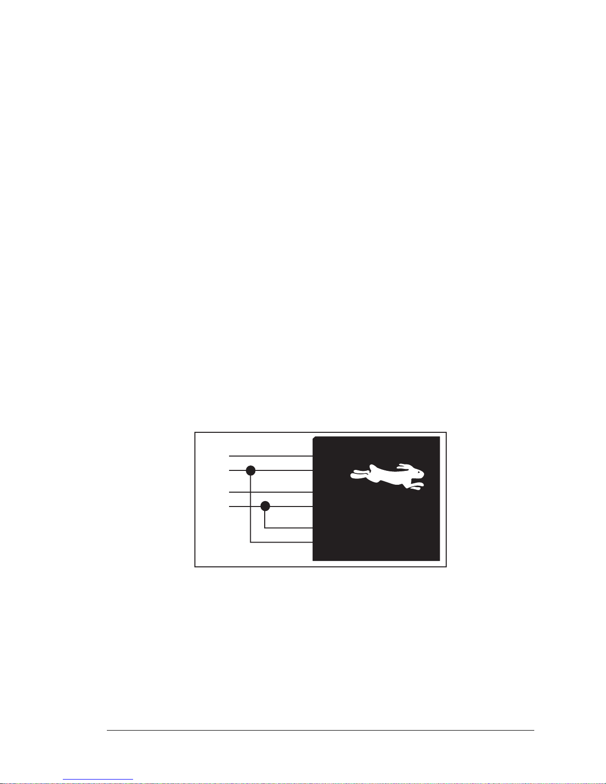
• FLOWCONTROL.C—This program demonstrates hardware flow control by configuring
Serial Port C for CTS/RTS with serial data coming from Serial Port D. The serial data
received are displayed in the STDIO window.
To set up the Prototyping Board, you will need to tie TxC and RxC
together on the RS-232 header at J2, and you will also tie TxD and
RxD together using the jumpers supplied in the Development Kit as
shown in the diagram.
A repeating triangular pattern should print out in the
STDIO window.
The program will periodically switch flow control on or off to demonstrate the effect of
no flow control.
Refer to the function description for
serDflowcontrolOn() in the Dynamic C
Function Reference Manual for a general description on how to set up flow-control
lines.
RabbitCore RCM3700 User’s Manual 19
Page 22

• PARITY.C—This program demonstrates the use of parity modes by
J2
RXC TXC RXE
GND
TXD
RXD
TXE
GND
J2
RXC TXC RXE
GND
TXD
RXD
TXE
GND
J2
RXC TXC RXE
GND
TXD
RXD
TXE
GND
J2
RXC TXC RXE
GND
TXD
RXD
TXE
GND
JP2
repeatedly sending byte values 0–127 from Serial Port D to Serial Port
C. The program will switch between generating parity or not on Serial
Port D. Serial Port C will always be checking parity, so parity errors
should occur during every other sequence.
To set up the Prototyping Board, you will need to tie TxD and RxC together on the
RS-232 header at J2 using the 0.1" jumpers supplied in the Development Kit as shown
in the diagram.
The Dynamic C STDIO window will display the error sequence.
• SIMPLE3WIRE.C—This program demonstrates basic RS-232 serial
communication. Lower case characters are sent by TxC, and are
received by RxD. The characters are converted to upper case and are
sent out by TxD, are received by RxC, and are displayed in the
Dynamic C STDIO window.
To set up the Prototyping Board, you will need to tie TxD and RxC together on the
RS-232 header at J2, and you will also tie RxD and TxC together using the 0.1" jumpers supplied in the Development Kit as shown in the diagram.
• SIMPLE5WIRE.C—This program demonstrates 5-wire RS-232 serial communication
with flow control on Serial Port C and data flow on Serial Port D.
To set up the Prototyping Board, you will need to tie TxD and RxD
together on the RS-232 header at J2, and you will also tie TxC and
RxC together using the 0.1" jumpers supplied in the Development Kit
as shown in the diagram.
Once you have compiled and run this program, you can test flow control by disconnecting TxC from RxC while the program is running. Characters will no
longer appear in the STDIO window, and will display again once TxC is connected
back to RxC.
SWITCHCHAR.C—This program transmits and then receives an ASCII string on Serial
•
Ports C and E. It also displays the serial data received from both ports in the
STDIO
window.
Before running this sample program, check to make sure that Serial
Port E is set up as an RS-232 serial port—pins 1–3 and pins 2–4 on
header JP2 on the Prototyping Board must be jumpered together using
the 2 mm jumpers supplied in the Development Kit. Then connect TxC
to RxE and connect RxC to TxE on the RS-232 header at J2 using the
0.1" jumpers supplied in the Development Kit as shown in the diagram.
RabbitCore RCM3700 User’s Manual 20
Page 23

NOTE: The following two sample programs illustrating RS-485 serial communication
JP2
will only work with the RCM3700 Prototyping Board.
• SIMPLE485MASTER.C—This program demonstrates a simple RS-485 transmission of
lower case letters to a slave RCM3700. The slave will send back converted upper case
letters back to the master RCM3700 and display them in the STDIO window. Use
SIMPLE485SLAVE.C to program the slave RCM3700, and check to make sure that
Serial Port E is set up as an RS-485 serial port—pins 3–5 and pins 4–6 on header JP2
must be jumpered together using the 2 mm jumpers supplied in the Development Kit.
• SIMPLE485SLAVE.C—This program demonstrates a simple RS-485
transmission of lower case letters to a master RCM3700. The slave
will send back converted upper case letters back to the master
RCM3700 and display them in the STDIO window. Use
SIMPLE485MASTER.C to program the master RCM3700, and check to make sure that
Serial Port E is set up as an RS-485 serial port—pins 3–5 and pins 4–6 on header JP2
must be jumpered together using the 2 mm jumpers supplied in the Development Kit.
RabbitCore RCM3700 User’s Manual 21
Page 24

3.2.3 A/D Converter Inputs
The following sample programs are found in the SAMPLES\RCM3700\ADC folder.
• AD_CALDIFF_CH.C—Demonstrates how to recalibrate one differential analog input
channel using two known voltages to generate the ca li br at io n constants for that channel.
Constants will be rewritten into user block data area.
Before running this program, make sure that pins 1–3 are connected on headers JP5,
JP6, and JP7 on the Prototyping Board. No pins are connected on header JP8.
• AD_CALMA_CH.C—Demonstrates how to recalibrate an A/D input channel being used to
convert analog current measurements to generate the calibration constants for that channel.
Before running this program, make sure that pins 3–5 are connected on headers JP5,
JP6, and JP7 on the Prototyping Board. Connect pins 1–2, 3–4, 5–6, 7–8 on header JP8.
• AD_CALSE_ALL.C—Demonstrates how to recalibrate all single-ended analog input
channels for one gain, using two known voltages to generate the calibration constants
for each channel. Constants will be rewritten into the user block data area.
Before running this program, make sure that pins 3–5 are connected on headers JP5,
JP6, and JP7 on the Prototyping Board. No pins are connected on header JP8.
• AD_CALSE_CHAN.C—Demonstrates how to recalibrate one single-ended analog input
channel with one gain using two known voltages to generate the calibration constants
for that channel. Constants will be rewritten into user block data area.
Before running this program, make sure that pins 3–5 are connected on headers JP5,
JP6, and JP7 on the Prototyping Board. No pins are connected on header JP8.
NOTE: The above sample programs will overwrite any existing calibration constants.
• AD_RDDIFF_CH.C—Demonstrates how to read an A/D input channel being used for a
differential input using previously defined calibration constants.
Before running this program, make sure that pins 1–3 are connected on headers JP5,
JP6, and JP7 on the Prototyping Board. No pins are connected on header JP8.
• AD_RDMA_CH.C—Demonstrates how to read an A/D input channel being used to convert analog current measurements using previously defined calibration constants for
that channel.
Before running this program, make sure that pins 3–5 are connected on headers JP5,
JP6, and JP7 on the Prototyping Board. Connect pins 1–2, 3–4, 5–6, 7–8 on header JP8.
• AD_RDSE_ALL.C—Demonstrates how to read all single-ended A/D input channels
using previously defined calibration constants.
Before running this program, make sure that pins 3–5 are connected on headers JP5,
JP6, and JP7 on the Prototyping Board. No pins are connected on header JP8.
RabbitCore RCM3700 User’s Manual 22
Page 25

• AD_SAMPLE.C—Demonstrates how to use a low-level driver on single-ended inputs.
The program will continuously display the voltage (average of 10 samples) that is present on the A/D channels.
Before running this program, make sure that pins 3–5 are connected on headers JP5,
JP6, and JP7 on the Prototyping Board. No pins are connected on header JP8.
• ANAINCONFIG.C—Demonstrates how to use the Register Mode method to read singleended analog input values for display as voltages. The sample program uses the function call anaInConfig() and the ADS7870 CONVERT line to accomplish this task.
Before running this program, make sure that pins 3–5 are connected on headers JP5, JP6,
and JP7 on the Prototyping Board. No pins are connected on header JP8. Also connect
PE4 on header J3 on the Prototyping Board to the CNVRT terminal on header J8.
If you use this sample program as a template for your own program, be aware that PE4
is also used for the IrDA FIR_SEL on the Prototyping Board. You will need to use
another parallel port line for the analog input if you are also using the IrDA transceiver.
• THERMISTOR.C—Demonstrates how to use analog input THERM_IN7 to calculate
temperature for display to the STDIO window. This sample program assumes that the
thermistor is the one included in the Development Kit whose values for beta, series
resistance, and resistance at standard temperature are given in the part specification.
Before running this program, install the thermistor into the AIN7 and AGND holes at
location J7 on the Prototyping Board.
Before running the next two sample programs, DNLOADCALIB.C or UPLOADCALIB.C,
connect your PC serial COM port to header J2 on the Prototyping Board as follows.
• Tx to RxE
• Rx to TxE
• GND to GND
Then connect pins 1–3 and 2–4 on header JP2 on the Prototyping Board.
You will need to run a serial utility such as Tera Term on your PC. You may download
Tera Term from hp.vector.co.jp/authors/VA002416/teraterm.html. Once Tera Term is run-
ning, configure the serial parameters as follows.
• Baud rate 19200, 8 bits, no parity, and 1 stop bit.
• Enable the "Local Echo" option.
• Set the line feed options to Receive = CR and Transmit = CR + LF.
Now press F9 to compile and run this program. Verify that the message "Waiting,
Please Send Data file" is being display in Tera Term display window before proceeding.
From within Tera Term, select File > Send File > Path and filename, then select the
OPEN option within the dialog box. Once the data file has been downloaded, it will indicate whether the calibration data were written successfully.
RabbitCore RCM3700 User’s Manual 23
Page 26

• DNLOADCALIB.C—Demonstrates how to retrieve analog calibration data to rewrite it
back to simulated EEPROM in flash with using a serial utility such as Tera Term.
• UPLOADCALIB.C—Demonstrates how to read calibrations constants from the user
block in flash memory and then transmitting the file using a serial port and a PC serial
utility such as Tera Term. Use DNLOADCALIB.C to download the calibration constants
created by this program.
RabbitCore RCM3700 User’s Manual 24
Page 27

4. HARDWARE REFERENCE
SRAM
11 MHz
osc
32 kHz
osc
RabbitCore Module
Customer-supplied
external 3 V battery
CMOS-level signals
RS-232, RS-485, IrDA
serial communication
drivers on motherboard
Customer-specific
applications
Battery-Backup
Circuit
Level
converter
Ethernet
Program
Flash
Serial
Flash
RABBIT
®
3000
Chapter 4 describes the hardware components and principal hardware
subsystems of the RCM3700. Appendix A, “RCM3700 Specifications,” provides complete physical and electrical specifications.
Figure 4 shows the Rabbit-based subsystems designed into the RCM3700.
RabbitCore RCM3700 User’s Manual 25
Figure 4. RCM3700 Subsystems
Page 28

4.1 RCM3700 Digital Inputs and Outputs
Note:
These pinouts are as seen on
the Bottom Side of the module.
PA6
PA4
PA2
PA0
PF0
PB2
PB4
PB7
PF5
PF7
PC1/PG2
PC3/PG3
PE5
PE1
PG7
/IOWR
PD4
/RES
GND
GND
PA7
PA5
PA3
PA1
PF1
PB0
PB3
PB5
PF4
PF6
PC0
PC2
PE7
PE4
PE0
PG6
/IORD
PD5
VBAT
+5 V
J1
Figure 5 shows the RCM3700 pinouts for header J1.
Header J1 is a standard 2 x 20 IDC header with a nominal 0.1" pitch.
RabbitCore RCM3700 User’s Manual 26
Figure 5. RCM3700 Pinouts
Page 29

Figure 6 shows the use of the Rabbit 3000 microprocessor ports in the RCM3700 modules.
Port A
Port B
Port D
(+Ethernet Port)
Port E
PA0PA7
PB0, PB7,
PB2PB5
PE0PE1,
PE4PE5,
PE7
PD4PD5
/RES,
/IOWR
Watchdog
11 Timers
Clock Doubler
Slave Port
Real-Time Clock
RAM
Backup Battery
Support
Flash
Port C
(Serial Ports C & D)
Programming
Port
(Serial Port A)
Ethernet
Port
4 Ethernet signals
PC6, STATUS
PB1, PC7, /RESET,
SMODE0, SMODE1
PC0, PC2
PC1, PC3
Port G
(Serial Ports E & F)
Port F
PF4PF7
Misc. I/O
/RES
/IORD
PG2PG3
PG6PG7
RABBIT
®
3000
Figure 6. Use of Rabbit 3000 Ports
The ports on the Rabbit 3000 microprocessor used in the RCM3700 are configurable, and
so the factory defaults can be reconfigured. Table 2 lists the Rabbit 3000 factory defaults
and the alternate configurations.
RabbitCore RCM3700 User’s Manual 27
Page 30

Table 2. RCM3700 Pinout Configurations
Pin Pin Name Default Use Alternate Use Notes
External data bus
1–8 PA[7:0] Parall el I/O
(ID0–ID7)
Slave port data bus
(SD0–SD7)
External Data Bus
9 PF1 Input/Output
10 PF0 Input/Output
11 PB0 Input/Output CLKB
12 PB2 Input/Output
13 PB3 Input/Output
14 PB4 Input/Output
15 PB5 Input/Output
16 PB7 Input/Output
Header J1
17 PF4 Input/Output
QD1A
CLKC
QD1B
CLKD
IA0
/SWR
IA1
/SRD
IA2
SA0
IA3
SA1
IA5
/SLAVEATTN
AQD1B
PWM0
External Address 0
Slave port write
External Address 1
Slave port read
External Address 2
Slave Port Address 0
External Address 3
Slave Port Address 1
External Address 5
Slave Port Attention
18 PF5 Input/Output
19 PF6 Input/Output
20 PF7 Input/Output
AQD1A
PWM1
AQD2B
PWM2
AQD2A
PWM3
21 PC0 Output TXD Serial Port D
22 PC1/PG2 Input/Output RXD/TXF
Serial Port D
Serial Port F
23 PC2 Output TXC Serial Port C
24 PC3/PG3 Input/Output RXC/RXF
25 PE7 Input/Output
RabbitCore RCM3700 User’s Manual 28
I7
/SCS
Serial Port C
Serial Port F
I/O Strobe 7
Slave Port Chip Select
Page 31

Table 2. RCM3700 Pinout Configurations (continued)
Pin Pin Name Default Use Alternate Use Notes
26 PE5 Input/Output
27 PE4 Input/Output
28 PE1 Input/Output
29 PE0 Input/Output
I5
INT1B
I4
INT0B
I1
INT1A
I0
INT0A
I/O Strobe 5
Interrupt 1B
I/O Strobe 4
Interrupt 0B
I/O Strobe 1
Interrupt 1A
I/O Strobe 0
Interrupt 0A
30 PG7 Input/Output RXE
Serial Port E
31 PG6 Input/Output TXE
32 /IOWR Output External write strobe
Header J1
33 /IORD Output External read strobe
34 PD4 Input/Output ATXB
Alternate Serial Port B
35 PD5 Input/Output ARXB
36 /RES Reset output Reset input
Reset output from Reset
Generator
37 VBAT
38 GND
39 +5 V
40 GND
RabbitCore RCM3700 User’s Manual 29
Page 32

4.1.1 Memory I/O Interface
The Rabbit 3000 address lines (A0–A18) and all the data lines (D0–D7) are routed internally to the onboard flash memory and SRAM chips. I/0 write (/IOWR) and I/0 read
(/IORD) are available for interfacing to external devices.
Parallel Port A can also be used as an external I/O data bus to isolate external I/O from the
main data bus. Parallel Port B pins PB2–PB5 and PB7 can also be used as an external
address bus.
When using the external I/O bus for either Ethernet or the LCD/keypad module on the
Prototyping Board, or for any other reason, you must add the following line at the beginning of your program.
#define PORTA_AUX_IO // required to enable external I/O bus
4.1.2 Other Inputs and Outputs
/RES is an output from the reset circuitry that can be used to reset other peripheral devices.
This pin can also be used to reset the microprocessor.
RabbitCore RCM3700 User’s Manual 30
Page 33
4.2 Serial Communication
TXC
RXC
RXD
TXD
TXF
RXF
PC2
PC3
PC0
PC1
PG2
PG3
J1: 23
J1: 24
J1: 21
J1: 22
The RCM3700 board does not have any serial transceivers directly on the board. However, a serial interface may be incorporated on the board the RCM3700 is mounted on. For
example, the Prototyping Board has RS-232, RS-485 and IrDA transceiver chips.
4.2.1 Serial Ports
There are five serial ports designated as Serial Ports A, C, D, E, and F. All five serial ports
can operate in an asynchronous mode up to the baud rate of the system clock divided by 8.
An asynchronous port can handle 7 or 8 data bits. A 9th bit address scheme, where an
additional bit is sent to mark the first byte of a message, is also supported.
Serial Port A is normally used as a programming port, but may be used either as an asynchronous or as a clocked serial port once application development has been completed and
the RCM3700 is operating in the Run Mode.
Serial Ports C and D can also be operated in the clocked serial mode. In this mode, a clock
line synchronously clocks the data in or out. Either of the two communicating devices can
supply the clock.
Serial Ports E and F can also be configured as HDLC serial ports. The IrDA protocol is
also supported in SDLC format by these two ports.
Serial Port F shares its pins with Serial Ports C and D on header J1, as shown in Figure 7.
The selection of port(s) depends on your need for two clocked serial ports (Serial Ports C
and D) vs. a second HDLC serial port (Serial Port F).
Figure 7. RCM3700 Serial Ports C, D, and F
The serial ports used are selected with the serXOpen function call, where X is the serial
port (C, D, or F). Remember that RxC and RxD on Serial Ports C and D cannot be used if
Serial Port F is being used
RabbitCore RCM3700 User’s Manual 31
Page 34
4.2.2 Ethernet Port
ETHERNET
RJ-45 Plug
1. E_Tx+
2. E_Tx
3. E_Rx+
6. E_Rx
1
8
RJ-45 Jack
Figure 8 shows the pinout for the RJ-45 Ethernet port (J3). Note that some Ethernet connectors are numbered in reverse to the order used here.
Figure 8. RJ-45 Ethernet Port Pinout
Two LEDs are placed next to the RJ-45 Ethernet jack, one to indicate an Ethernet link
(LINK) and one to indicate Ethernet activity (ACT).
The RJ-45 connector is shielded to minimize EMI effects to/from the Ethernet signals.
RabbitCore RCM3700 User’s Manual 32
Page 35

4.2.3 Serial Programming Port
The RCM3700 programming port is accessed through header J2 or over an Ethernet connection via the RabbitLink EG2110. The programming port uses the Rabbit 3000’s Serial
Port A for communication. Dynamic C uses the programming port to download and debug
programs.
The programming port is also used for the following operations.
• Cold-boot the Rabbit 3000 on the RCM3700 after a reset.
• Remotely download and debug a program over an Ethernet connection using the
RabbitLink EG2110.
• Fast copy designated portions of flash memory from one Rabbit-based board (the
master) to another (the slave) using the Rabbit Cloning Board.
In addition to Serial Port A, the Rabbit 3000 startup-mode (SMODE0, SMODE1), status,
and reset pins are available on the programming port.
The two startup mode pins determine what happens after a reset—the Rabbit 3000 is
either cold-booted or the program begins executing at address 0x0000.
The status pin is used by Dynamic C to determine whether a Rabbit microprocessor is
present. The status output has three different programmable functions:
1. It can be driven low on the first op code fetch cycle.
2. It can be driven low during an interrupt acknowledge cycle.
3. It can also serve as a general-purpose CMOS output.
The /RESET_IN pin is an external input that is used to reset the Rabbit 3000 and the
RCM3700 onboard peripheral circuits. The serial programming port can be used to force a
hard reset on the RCM3700 by asserting the /RESET_IN signal.
Alternate Uses of the Programming Port
All three clocked Serial Port A signals are available as
• a synchronous serial port
• an asynchronous serial port, with the clock line usable as a general CMOS input
The programming port may also be used as a serial port once the application is running.
The SMODE pins may then be used as inputs and the status pin may be used as an output.
Refer to the Rabbit 3000 Microprocessor User’s Manual for more information.
RabbitCore RCM3700 User’s Manual 33
Page 36
4.3 Serial Programming Cable
+V
/RESET
LDE0
LED2
LED4
LED6
GND
+BKLT
/CS
LED1
LED3
LED5
GND
GND
A2
A1
D1D3D5
D7
GND
A3A1D0D2D4D6GND
+BKLT
/CS
LED1
LED3
LED5
GND
GND
A2
A0
D1D3D5
D7
L2
C1
C2
IR1
R1
R2
R3
R4
Rx
Tx
R5
R6
C3
R9
R7
R8
JP1
J1
+485
GND
485
JP2
R12
R11
U3
C4
C7
C8
C10
R13
C11
U4
C5
C6
C9
J2
GND
/IORD
PB5
PB3
PA0
PA6
PB0
/RES
+5V
PF4
PF6
PC1/PG2
PC0_TXD
PE5
PE1
PG7_RXE
PD4
VBAT
PA4 PA2
/IOWR
PE7
PB4
PB2
PA1
PA3
PA5
PA7
PB7
PF0
PF1
PF5
PF7
PE4
PE0
PD5
PG6
TXE
PC2
TXC
PC3/
PG3
GND
RXC TXC RXE
GND
NC
U1
C12
C13
C15
C14
L1
C17
U2
C18
U6
R14
D1
C19
D2
J4
DCIN
+3.3V
GND
+5V
+5V
GND
+3.3V
LCD1JB
LCD1JC
LCD1JA
U5
C16
R15
BT1
GND
TXD
RXD
TXE
GND
TCM_SMT_SOCKET
+5V
VBAT
PD5
/IORD
PG6_TXE
PE0
PE4
PE7
PC2_TXC
PC0_TXD
PF6
PF4
PB5
PB3
PB0
PF1
PA1
PA3
PA5
PA7
J5
GND
R16
GND
/RES
PD4
/IOWR
PE1
PE5
PC3/PG3
PF7
PF5
PB7
PB4
PB2
PF0
PA0
PA2
PA4
PA6
PG7
RXE
PC1/
PG2
C22
C26
R21
R18
C20
R19
C21
R20
R22
JP4
1
2
RP1
CX1 CX2
CX3
CX4
CX5
CX6
CX7
CX8
CX9
CX10CX11
UX2
UX1
U8
R23
C24 C25
C23
U7
C27
R25
R24
C28
R26
R27
R28
R29
JP8
R30 R31 R32
R33
R34
R35
R36
C35
R43
C29
J7
THERMISTOR
R37
J8
VREF
AGND
R44
THERM_IN
AIN
06050403020100
AIN
AGND
R38
C30
C31
C32
C33
C34
R39 R40
R41 R42
R48
DS1
DS2
R45
R49
R46
DS3
R47
S3
S2S1
CONVERT
JP5
JP6
JP7
NC
NCNCNC
NC
NC
+V
/RSTET
LED0
LED2
LED4
LED6
GNDA3A1D0D2D4D6
RCM36/37XX SERIES
PROTOTYPING BOARD
RESET
RESET
R24
R2
C18
C34
RP1
RP2
R18
R36
C35
C19
C26
C27
C28
R15
R16
C36
C39
R13
U1
C25
JP1
C7
JP3
J2
C33
C32
C30
C31
C15
C17
C20
C38
C41
U4
R6
R11
C37
R4 R5
U5
C29
JP2
Y1
C40
C10
Q1
R7
C49
L2
L1
C14
C12
C22
U8
C23
Y3
C57
R31
C58
R29
DS2
R32
R30
DS1
J3
R34
C16
R28
T1
C24
C21
D1
U6
C53
R26
U3
R33
C8
U11
L4
L3
C54 C55
L6
R27
Colored
edge
To
PC COM port
Blue
shrink wrap
PROG
DIAG
Programming
Cable
PROG
J2
RESET RCM3700 when changing mode:
Press RESET button (if using Prototyping Board),
OR
Cycle power off/on
after removing or attaching programming cable.
The programming cable is used to connect the programming port of the RCM3700 to a PC
serial COM port. The programming cable converts the RS-232 voltage levels used by the
PC serial port to the CMOS voltage levels used by the Rabbit 3000.
When the
PROG connector on the programming cable is connected to the RCM3700 pro-
gramming port, programs can be downloaded and debugged over the serial interface.
The DIAG connector of the programming cable may be used on header J2 of the RCM3700
with the RCM3700 operating in the Run Mode. This allows the programming port to be
used as a regular serial port.
4.3.1 Changing Between Program Mode and Run Mode
The RCM3700 is automatically in Program Mode when the PROG connector on the programming cable is attached, and is automatically in Run Mode when no programming
cable is attached. When the Rabbit 3000 is reset, the operating mode is determined by the
state of the SMODE pins. When the programming cable’s PROG connector is attached,
the SMODE pins are pulled high, placing the Rabbit 3000 in the Program Mode. When the
programming cable’s PROG connector is not attached, the SMODE pins are pulled low,
causing the Rabbit 3000 to operate in the Run Mode.
RabbitCore RCM3700 User’s Manual 34
Figure 9. Switching Between Program Mode and Run Mode
Page 37

A program “runs” in either mode, but can only be downloaded and debugged when the
RCM3700 is in the Program Mode.
Refer to the Rabbit 3000 Microprocessor User’s Manual for more information on the programming port and the programming cable.
4.3.2 Standalone Operation of the RCM3700
The RCM3700 must be programmed via the RCM3700 Prototyping Board or via a similar
arrangement on a customer-supplied board. Once the RCM3700 has been programmed
successfully, remove the programming cable from the programming connector and reset
the RCM3700. The RCM3700 may be reset by cycling the power off/on or by pressing the
RESET button on the Prototyping Board. The RCM3700 module may now be removed
from the Prototyping Board for end-use installation.
CAUTION: Power to the Prototyping Board or other boards should be disconnected
when removing or installing your RCM3700 module to protect against inadvertent
shorts across the pins or damage to the RCM3700 if the pins are not plugged in correctly. Do not reapply power until you have verified that the RCM3700 module is
plugged in correctly.
RabbitCore RCM3700 User’s Manual 35
Page 38

4.4 Other Hardware
4.4.1 Clock Doubler
The RCM3700 takes advantage of the Rabbit 3000 microprocessor’s internal clock doubler .
A built-in clock doubler allows half-frequency crystals to be used to reduce radiated emissions. The 22.1 MHz frequency specified for the RCM3700 is generated using a 11.06 MHz
resonator.
The clock doubler may be disabled if 22.1 MHz clock speeds are not required. This will
reduce power consumption and further reduce radiated emissions. Disable the clock
doubler by adding a simple configuration macro as shown below.
1. Select the “Defines” tab from the Dynamic C Options > Project Options menu.
2. Add the line CLOCK_DOUBLED=0 to always disable the clock doubler.
The clock doubler is enabled by default, and usually no entry is needed. If you need to
specify that the clock doubler is always enabled, add the line CLOCK_DOUBLED=1 to
always enable the clock doubler.
3. Click OK to save the macro. The clock doubler will now remain off whenever you are
in the project file where you defined the macro.
4.4.2 Spectrum Spreader
The Rabbit 3000 features a spectrum spreader, which helps to mitigate EMI problems. By
default, the spectrum spreader is on automatically, but it may also be turned off or set to a
stronger setting. The spectrum spreader settings may be changed through a simple configuration macro as shown below.
1. Select the “Defines” tab from the Dynamic C Options > Project Options menu.
2. Normal spreading is the default, and usually no entry is needed. If you need to specify
normal spreading, add the line
ENABLE_SPREADER=1
For strong spreading, add the line
ENABLE_SPREADER=2
To disable the spectrum spreader, add the line
ENABLE_SPREADER=0
NOTE: The strong spectrum-spreading setting is not recommended since it may limit
the maximum clock speed or the maximum baud rate. It is unlikely that the strong
setting will be needed in a real application.
3. Click OK to save the macro. The spectrum spreader will now be set to the state specified
by the macro value whenever you are in the project file where you defined the macro.
NOTE: Refer to the Rabbit 3000 Microprocessor User’s Manual for more information
on the spectrum-spreading setting and the maximum clock speed.
RabbitCore RCM3700 User’s Manual 36
Page 39

4.5 Memory
4.5.1 SRAM
RCM3700 series boards have 256K–512K of SRAM.
4.5.2 Flash EPROM
RCM3700 series boards also have 256K–512K of flash EPROM.
NOTE: Rabbit recommends that any customer applications should not be constrained by
the sector size of the flash EPROM since it may be necessary to change the sector size
in the future.
Writing to arbitrary flash memory addresses at run time is al so discouraged. Instead, use a
portion of the “user block” area to store persistent data. The functions writeUser-
Block and readUserBlock are provided for this. Refer to the Rabbit 3000 Micropro-
cessor Designer’s Handbook
A Flash Memory Bank Select jumper configuration option based on 0 surface-mounted
resistors exists at header JP1 on the RCM3700 modules. This option, used in conjunction
with some configuration macros, allows Dynamic C to compile two different co-resident
programs for the upper and lower halves of the 512K flash in such a way that both programs start at logical address 0000. This is useful for applications that require a resident
download manager and a separate downloaded program. See T echnical Note TN218 in the
online documentation, Implementing a Serial Download Manager for a 256K Flash, for
details.
for additional information.
4.5.3 Serial Flash
A 1Mbyte serial flash is available to store data and Web pages. Sample programs in the
SAMPLES\RCM3700 folder illustrate the use of the serial flash.
4.5.4 Dynamic C BIOS Source Files
The Dynamic C BIOS source files handle different standard RAM and flash EPROM sizes
automatically.
RabbitCore RCM3700 User’s Manual 37
Page 40

5. SOFTWARE REFERENCE
Dynamic C is an integrated development system for writing
embedded software. It runs on an IBM-compatible PC and is
designed for use with Rabbit single-board computers and other
single-board computers based on the Rabbit microprocessor.
Chapter 5 describes the libraries and function calls related to the
RCM3700.
5.1 More About Dynamic C
Dynamic C has been in use worldwide since 1989. It is specially designed for programming embedded systems, and features quick compile and interactive debugging. A complete reference guide to Dynamic C is contained in the Dynamic C User’s Manual and in
the Dynamic C Function Reference Manual.
You have a choice of doing your software development in the flash memory or in the
SRAM included on the RCM3700. The flash memory and SRAM options are selected
with the Options > Compiler menu.
The advantage of working in RAM is to save wear on the flash memory, which is limited
to about 100,000 write cycles. The disadvantage is that the code and data might not both
fit in RAM.
NOTE: An application can be compiled in RAM, but cannot run standalone from RAM
after the programming cable is disconnected. All standalone applications can only run
from flash memory.
NOTE: Do not depend on the flash memory sector size or type in your program logic.
The RCM3700 and Dynamic C were designed to accommodate flash devices with
various sector sizes in response to the volatility of the flash-memory market.
Developing software with Dynamic C is simple. Users can write, compile, and test C and
assembly code without leaving the Dynamic C development environment. Debugging
occurs while the application runs on the target. Alternatively, users can compile a program
to an image file for later loading. Dynamic C runs on PCs under Windows 2000/NT and
later—see Rabbit’s Technical Note TN257, Running Dynamic C® With Windows Vista®,
for additional information if you are using a Dynamic C release prior to v. 9.60 under
Windows Vista. Programs can be downloaded at baud rates of up to 460,800 bps after the
program compiles.
RabbitCore RCM3700 User’s Manual 38
Page 41

Dynamic C has a number of standard features. Some of these standard features are listed
below.
• Full-feature source and assembly-level debugger, no in-circuit emulator required.
• Royalty-free TCP/IP stack with source code and most common protocols.
• Hundreds of functions in source-code libraries and sample programs:
exceptionally fast support for floating-point arithmetic and transcendental functions.
RS-232 and RS-485 serial communication.
analog and digital I/O drivers.
2
I
C, SPI, GPS, file system.
LCD display and keypad drivers.
• Powerful language extensions for cooperative or preemptive multitasking
• Loader utility program (Rabbit Field Utility) to load binary images to Rabbit-based tar-
gets without the presence of Dynamic C.
• Provision for customers to create their own source code libraries and augment on-line
help by creating “function description” block comments using a special format for
library functions.
• Standard debugging features:
Breakpoints—Set breakpoints that can disable interrupts.
Single-stepping—Step into or over functions at a source or machine code level, µC/OS-II aware.
Code disassembly—The disassembly window displays addresses, opcodes, mnemonics, and
machine cycle times. Switch between debugging at machine-code level and source-code level by
simply opening or closing the disassembly window.
Watch expressions—Watch expressions are compiled when defined, so complex expressions
including function calls may be placed into watch expressions. Watch expressions can be updated
with or without stopping program execution.
Register window—All processor registers and flags are displayed. The contents of general registers
may be modified in the window by the user.
Stack window—shows the contents of the top of the stack.
Hex memory dump—displays the contents of memo ry at any add ress.
STDIO window—
detected for debugging purposes.
printf outputs to this window and keyboard input on the host PC can be
printf output may also be sent to a serial port or file.
RabbitCore RCM3700 User’s Manual 39
Page 42

5.2 Dynamic C Functions
The functions described in this section are for use with the Prototyping Board features.
The source code is in the
the SAMPLES\RCM3720 folder , depending on which Prototyping Board you will be using,
if you need to modify it for your own board design.
Other generic functions applicable to all devices based on Rabbit microprocessors are
described in the Dynamic C Function Reference Manual.
RCM37xx.LIB
library in the Dynamic C SAMPLES\RCM3700 or
RabbitCore RCM3700 User’s Manual 40
Page 43

5.2.1 Board Initialization
void brdInit (void);
Call this function at the beginning of your program. This function initializes Parallel Ports A through G
for use with the RCM3700 Prototyping Board or the RCM3720 Prototyping Board.
The
brdInit
at compile time:
• Any RCM3700 RabbitCore module (except the RCM3720) will have its I/O ports configured for an
RCM3700 Prototyping Board.
• An RCM3720 RabbitCore module will have its I/O ports configured for an RCM3720 Prototyping
Board.
You may override these default settings to run an RCM3720 RabbitCore module on the RCM3700 Prototyping Board or to run another RCM3700 RabbitCore module on the RCM3720 Prototyping Board by
adding the following macro to the program you will be running.
• To run an RCM3720 RabbitCore module on an RCM3700 Prototyping Board, add the following
macro at the top of the program you will be running.
#define RCM3700_PROTOBOARD
Sample programs that are specifically designed for the RCM3700 Prototyping Board already ha ve
this macro included. When you run a sample program designed for the RCM3700 Prototyping
Board on an RCM3720, a warning message will be displayed to inform you of that. You can disable
the warning by commenting out the line indicated by the compiler.
• To run an RCM3700 RabbitCore module (other than the RCM3720) on an RCM3720 Prototyping
Board, add the following macro at the top of the program you will be running.
#define RCM3720_PROTOBOARD
Summary of Initialization
1. I/O port pins are configured for Prototyping Board operation.
2. Unused configurable I/O are set as tied inputs or outputs.
3. The LCD/keypad module is disabled.
4. RS-485 is not enabled.
5. RS-232 is not enabled.
6. The IrDA transceiver is disabled.
7. LEDs are off.
8. The A/D converter is reset and SCLKB is to 57,600 bps (RCM3700 Prototyping Board only).
9. The A/D converter calibration constants are read (this function cannot run in RAM) (RCM3700
Prototyping Board only).
10. Ethernet select is disabled.
11. Serial flash select is disabled.
function is set up to a default I/O configuration based on the RabbitCore module detected
CAUTION: Pin PB7 is connected as both switch S2 and as an external I/O bus on the RCM3700
Prototyping Board. Do not use S2 when the LCD/keypad module is installed.
CAUTION: Pins PC1 and PG2 are tied together, and pins PC3 and PG3 are tied together on the
RCM3700 RabbitCore module. Both pairs of pins are connected to the IrDA transceiver and to
the RS-232 transceiver via serial ports on the RCM3700 Prototyping Board. Do not enable both
transceivers on the RCM3700 Prototyping Board at the same time.
RETURN VALUE
None.
RabbitCore RCM3700 User’s Manual 41
Page 44

5.2.2 Analog Inputs
NOTE: The function calls for the A/D converter in this section will work only with the
RCM3700 Prototyping Board.
unsigned int anaInConfig(unsigned int
instructionbyte, unsigned int cmd, long baud);
Use this function to configure the ADS7870 A/D converter. This function will address the ADS7870 in
Register Mode only, and will return error if you try the Direct Mode. Section B.1.5 provides additional
addressing and command information for the ADS7870 A/D converter.
ADS7870 Signal ADS7870 State RCM3700 Function/State
LN0 Input AIN0
LN1 Input AIN1
LN2 Input AIN2
LN3 Input AIN3
LN4 Input AIN4
LN5 Input AIN5
LN6 Input AIN6
LN7 Input AIN7
/RESET Input Board reset device
RISE/FALL Input Pulled up for SCLK active on rising edge
PIO0 Input Pulled down
PIO1 Input Pulled down
PIO2 Input Pulled down
PIO3 Input Pulled down
CONVERT Input Pulled down
BUSY Output PD1 pulled down; logic high state converter is busy
CCLKCNTRL Input Pulled down; 0 state sets CCLK as input
CCLK Input Pulled down; external conversion clock
SCLK Input PB0; serial data transfer clock
SDI Input PD4; 3-wire mode for serial data input
SDO Output PD5; serial data output /CS driven
/CS Input PD2 pulled up; active-low enables serial interface
BUFIN Input Driven by VREF; reference buffer amplifier
VREF Output Connected to BUFIN
BUFOUT Output VREF output
RabbitCore RCM3700 User’s Manual 42
Page 45

PARAMETERS
instructionbyte
is the instruction byte that will initiate a read or write operation at 8 or 16 bits on
the designated register address. For example,
checkid = anaInConfig(0x5F, 0, 9600); // read ID and set baud rate
cmd
refers to the command data that configure the registers addressed by the instruction byte. Enter 0 if
you are performing a read operation. For example,
i = anaInConfig(0x07, 0x3b, 0); // write ref/osc reg and enable
baud
is the serial clock transfer rate of 9600 to 57,600 bps.
baud
must be set the first time this functi on
is called. Enter 0 for this parameter thereafter, for example,
anaInConfig(0x00, 0x00, 9600); // resets device and sets baud
RETURN VALUE
0 on write operations,
data value on read operations
SEE ALSO
anaInDriver, anaIn, brdInit
RabbitCore RCM3700 User’s Manual 43
Page 46

unsigned int anaInDriver(unsigned int cmd,
unsigned int len);
Reads the voltage of an analog input channel by serial-clocking an 8-bit command to the ADS7870 A/D
converter by the Direct Mode method. This function assumes that Mode1 (most significant byte first) and
the A/D converter oscillator have been enabled. See
The conversion begins immediately after the last data bit has been transferred. An exception error will
occur if Direct Mode bit D7 is not set.
PARAMETERS
cmd contains a gain code and a channel code as follows.
D7—1; D6–D4—Gain Code; D3–D0—Channel Code
Use the following calculation and the tables below to determine cmd:
cmd = 0x80 | (gain_code*16) + channel_code
Gain Code Multiplier
0x1
1x2
2x4
3x5
anaInConfig()
for the setup.
4x8
5x10
6x16
7x20
Channel Code
Differential Input
Lines
Channel Code
Single-Ended
Input Lines
0 +AIN0 -AIN1 8 AIN0 AIN0*
1 +AIN2 -AIN3 9 AIN1 AIN1*
2 +AIN4 -AIN5 10 AIN2 AI N2*
†
3
+AIN6 -AIN7 11 AIN3 AIN3
4 -AIN0 +AIN1 12 AIN4 A IN4
5 -AIN2 +AIN3 13 AIN5 A IN5
6 -AIN4 +AIN5 14 AIN6 A IN6
7* -AIN6 +AIN7 15 AIN7 AIN7*
* Negative input is ground.
† Not accessible on RCM3700 Prototyping Board
*
4–20 mA
Lines
len, the output bit length, is always 12 for 11-bit conversions
RETURN VALUE
RabbitCore RCM3700 User’s Manual 44
Page 47

A value corresponding to the voltage on the analog input channel:
0–2047 for 11-bit conversions (bit 12 for sign)
-1 overflow or out of range
-2 conversion incomplete, busy bit timeout
SEE ALSO
anaInConfig, anaIn, brdInit
RabbitCore RCM3700 User’s Manual 45
Page 48
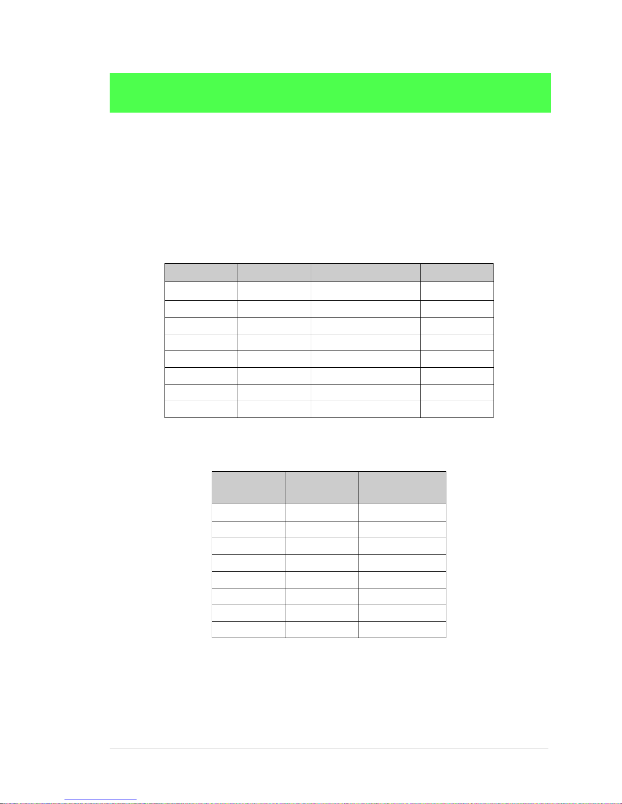
unsigned int anaIn(unsigned int channel,
int opmode, int gaincode);
Reads the value of an analog input channel using the direct method of addressing the ADS7870 A/D
converter. The A/D converter is enabled the first time this function is called—this will take approximately 1 second to ensure that the A/D converter capacitor is fully charged.
PARAMETERS
channel
opmode
is the channel number (0 to 7) corresponding to ADC_IN0 to ADC_IN7
is the mode of operation:
SINGLE
DIFF
mAMP
—single-ended input
—differential input
—4–20 mA input
channel SINGLE DIFF mAMP
0 +AIN0 +AIN0 -AIN1
1 +AIN1 +AIN1 -AIN0* +AIN1*
2 +AIN2 +AIN2 -AIN3 +AIN2*
3 +AIN3 +AIN3 -AIN2* +AIN3
4 +AIN4 +AIN4 -AIN5 +AIN4
5 +AIN5 +AIN5 -AIN4* +AIN5
6 +AIN6 +AIN6 -AIN7* +AIN6
7 +AIN7 +AIN7 -AIN6* +AIN7*
+AIN0
*
* Not accessible on RCM3700 Prototyping Board.
gaincode is the gain code of 0 to 7
Gain Code Multiplier
0 x1 0–20
1 x2 0–10
2x4 0–5
3x5 0–4
4 x8 0–2.5
5 x10 0–2
6 x16 0–1.25
7 x20 0–1
* Applies to RCM3700 Prototy ping Board.
Voltage Range
(V)
*
RabbitCore RCM3700 User’s Manual 46
Page 49

RETURN VALUE
A value corresponding to the voltage on the analog input channel:
0–2047 for 11-bit A/D conversions (signed 12th bit)
ADOVERFLOW
(defined macro = -4096) if overflow or out of range
-4095 if conversion is incomplete or busy-bit timeout
SEE ALSO
anaIn, anaInConfig, anaInDriver
RabbitCore RCM3700 User’s Manual 47
Page 50
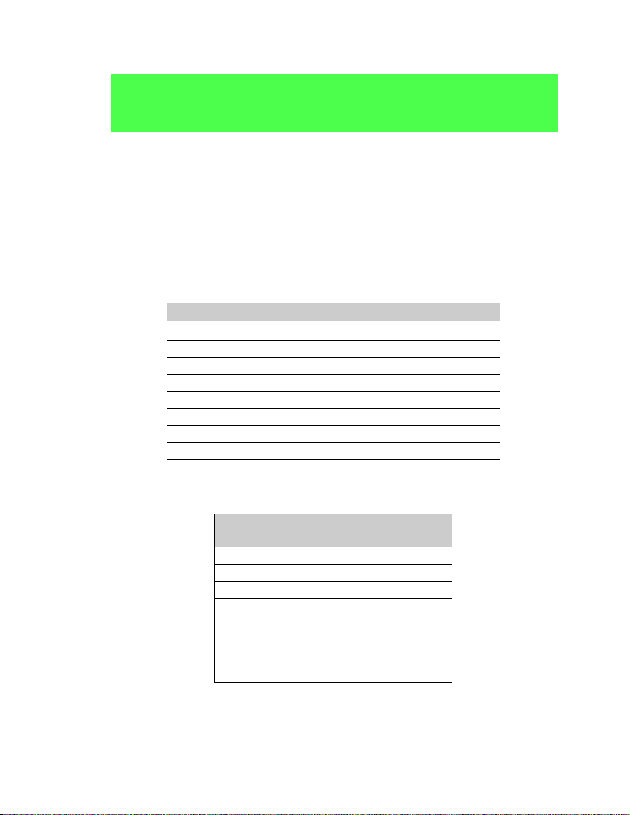
int anaInCalib(int channel, int opmode,
int gaincode, int value1, float volts1,
int value2, float volts2);
Calibrates the response of the desired A/D converter channel as a linear function using the two conversion points provided. Four values are calculated and placed into global tables to be later stored into simulated EEPROM using the function
voltage offset.
PARAMETERS
channel is the analog input channel number (0 to 7) corresponding to ADC_IN0 to ADC_IN7
opmode is the mode of operation:
SINGLE—single-ended input
DIFF—differential input
mAMP—milliamp input
channel SINGLE DIFF mAMP
0 +AIN0 +AIN0 -AIN1
1 +AIN1 +AIN1 -AIN0* +AIN1*
2 +AIN2 +AIN2 -AIN3 +AIN2*
3 +AIN3 +AIN3 -AIN2* +AIN3
4 +AIN4 +AIN4 -AIN5 +AIN4
5 +AIN5 +AIN5 -AIN4* +AIN5
6 +AIN6 +AIN6 -AIN7* +AIN6
7 +AIN7 +AIN7 -AIN6* +AIN7*
anaInEEWr()
. Each channel will have a linear constant and a
*
+AIN0
* Not accessible on RCM3700 Prototyping Board.
gaincode is the gain code of 0 to 7
Gain Code Multiplier
0 x1 0–20
1 x2 0–10
2x4 0–5
3x5 0–4
4 x8 0–2.5
5 x10 0–2
6 x16 0–1.25
7 x20 0–1
* Applies to RCM3700 Prototy ping Board.
Voltage Range
(V)
*
RabbitCore RCM3700 User’s Manual 48
Page 51

value1 is the first A/D converter channel value (0–2047)
volts1 is the voltage or current corresponding to the first A/D converter channel value (0 to +20 V or
4 to 20 mA)
value2 is the second A/D converter channel value (0–2047)
volts2 is the voltage or current corresponding to the first A/D converter channel value (0 to +20 V or
4 to 20 mA)
RETURN VALUE
0 if successful.
-1 if not able to make calibration constants.
SEE ALSO
anaIn, anaInVolts, anaInmAmps, anaInDiff, anaInCalib, brdInit
RabbitCore RCM3700 User’s Manual 49
Page 52
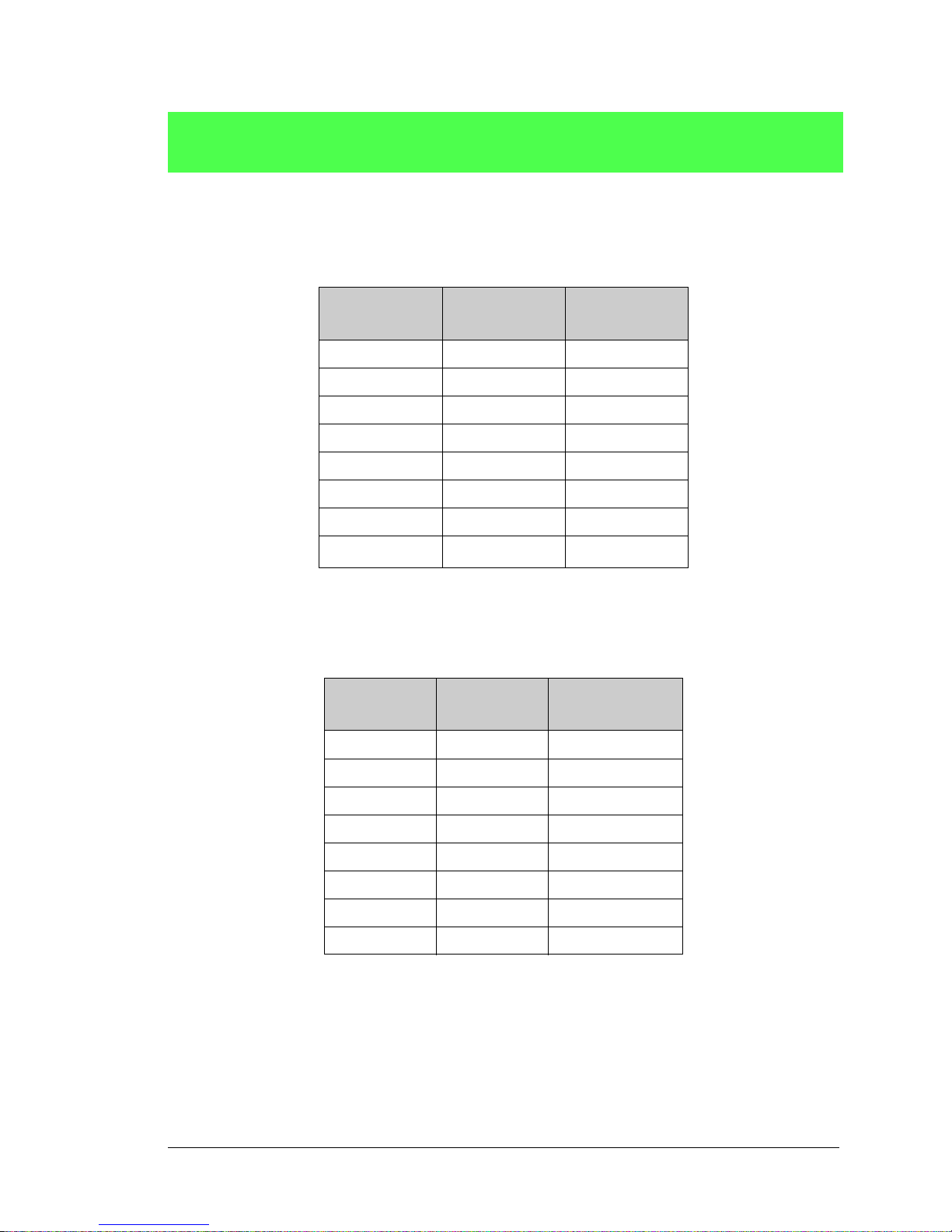
float anaInVolts(unsigned int channel,
unsigned int gaincode);
Reads the state of a single-ended analog input channel and uses the calibration constants previously set
using
anaInCalib
PARAMETERS
channel is the channel number (0–7)
to convert it to volts.
Channel Code
0 +AIN0 0–20
1 +AIN1 0–20
2 +AIN2 0–20
3 +AIN3 0–20
4 +AIN4 0–20
5 +AIN5 0–20
6 +AIN6 0–20
7+AIN7
* Negative input is ground.
† Applies to RCM3700 Prototy ping Board.
‡ Used for thermistor in sample program.
gaincode is the gain code of 0 to 7
Gain Code Multiplier
0 x1 0–20
Single-Ended
Input Lines
*
Voltage Range
(V)
‡
0–2
Voltage Range
(V)
†
*
RETURN VALUE
A voltage value corresponding to the voltage on the analog input channel.
ADOVERFLOW (defined macro = -4096) if overflow or out of range.
SEE ALSO
anaInCalib, anaIn, anaInmAmps, brdInit
RabbitCore RCM3700 User’s Manual 50
1 x2 0–10
2x4 0–5
3x5 0–4
4 x8 0–2.5
5 x10 0–2
6 x16 0–1.25
7 x20 0–1
* Applies to RCM3700 Prototy ping Board.
Page 53

float anaInDiff(unsigned int channel,
unsigned int gaincode);
Reads the state of differential analog input channels and uses the calibration constants previously set
using
anaInCalib
PARAMETERS
channel is the analog input channel number (0 to 7) corresponding to ADC_IN0 to ADC_IN7
to convert it to volts.
channel DIFF
0 +AIN0 -A IN1
1 +AIN1 -A IN0 —
2 +AIN2 -A IN3 -20 to +20*
3 +AIN3 -A IN2 —
4 +AIN4 -A IN5 -20 to +20*
5 +AIN5 -A IN4 —
6 +AIN6 -A IN7 —
7 +AIN7 -A IN6 —
* Applies to RCM3700 Prototy ping Board.
gaincode is the gain code of 0 to 7
Gain Code Multiplier
0 x1 0–20
1 x2 0–10
2x4 0–5
Voltage Range
(V)
-20 to +20
Voltage Range
(V)
*
*
RETURN VALUE
A voltage value corresponding to the voltage on the analog input channel.
ADOVERFLOW (defined macro = -4096) if overflow or out of range.
SEE ALSO
anaInCalib, anaIn, anaInmAmps, brdInit
RabbitCore RCM3700 User’s Manual 51
3x5 0–4
4 x8 0–2.5
5 x10 0–2
6 x16 0–1.25
7 x20 0–1
* Applies to RCM3700 Prototy ping Board.
Page 54
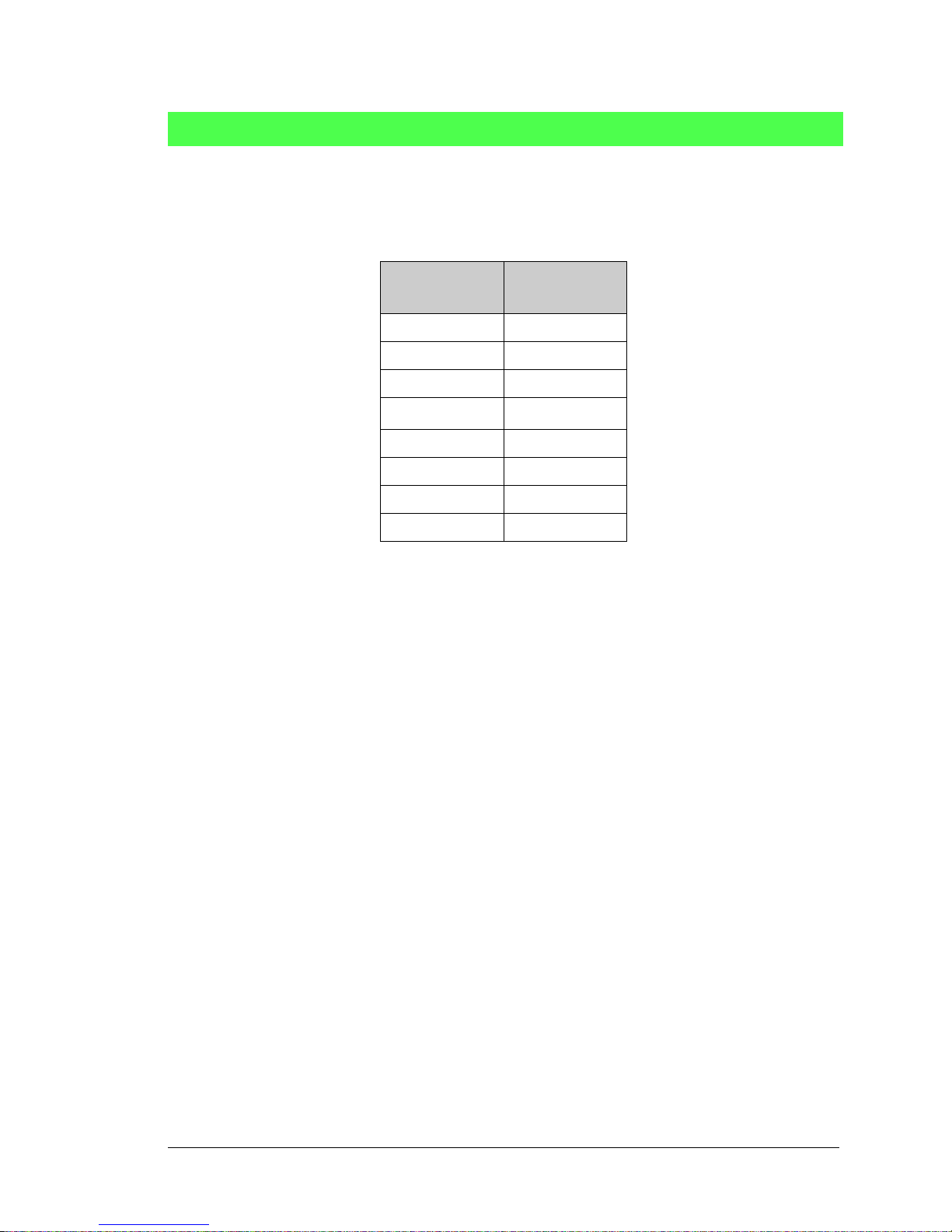
float anaInmAmps(unsigned int channel);
Reads the state of an analog input channel and uses the calibration constants previously set using
anaInCalib
PARAMETERS
channel is the channel number (0–7)
to convert it to current.
Channel Code
4–20 mA
Input Lines
*
0+AIN0
1+AIN1
2+AIN2
3
+AIN3
†
4+AIN4*
5+AIN5*
6+AIN6*
7+AIN7
* Negative input is ground.
† Applies to RCM3700 Prototyp-
ing Board.
RETURN VALUE
A current value between 4.00 and 20.00 mA corresponding to the current on the analog input channel.
ADOVERFLOW (defined macro = -4096) if overflow or out of range.
SEE ALSO
anaInCalib, anaIn, anaInVolts
RabbitCore RCM3700 User’s Manual 52
Page 55

root int anaInEERd(unsigned int channel,
unsigned int opmode, unsigned int gaincode);
Reads the calibration constants, gain, and offset for an input based on their designated position in the
simulated EEPROM area of the flash memory, and places them into global tables for analog inputs. The
constants are stored in the top 2K of the reserved user block memory area 0x1C00–0x1FFF. Depending
on the flash size, the following macros can be used to identify the starting address for these locations.
ADC_CALIB_ADDRS, address start of single-ended analog input channels
ADC_CALIB_ADDRD, address start of differential analog input channels
ADC_CALIB_ADDRM, address start of milliamp analog input channels
NOTE: This function cannot be run in RAM.
PARAMETER
channel is the analog input channel number (0 to 7) corresponding to ADC_IN0 to ADC_IN7
opmode is the mode of operation:
SINGLE—single-ended input line
DIFF—differential input line
mAMP—milliamp input line
channel SINGLE DIFF mAMP
0 +AIN0 +AIN0 -AIN1
1 +AIN1 +AIN1 -AIN0* +AIN1*
2 +AIN2 +AIN2 -AIN3 +AIN2*
3 +AIN3 +AIN3 -AIN2* +AIN3
4 +AIN4 +AIN4 -AIN5 +AIN4
5 +AIN5 +AIN5 -AIN4* +AIN5
6 +AIN6 +AIN6 -AIN7* +AIN6
7 +AIN7 +AIN7 -AIN6* +AIN7*
+AIN0
*
ALLCHAN read all channels for selected opmode
* Not accessible on RCM3700 Prototyping Board.
RabbitCore RCM3700 User’s Manual 53
Page 56

gaincode is the gain code of 0 to 7. The gaincode parameter is ignored when channel is ALLCHAN.
RETURN VALUE
0 if successful.
-1 if address is invalid or out of range.
-2 if there is no valid ID block.
SEE ALSO
anaInEEWr, anaInCalib
Gain Code
Voltage Range
(V)
*
0 0–20
1 0–10
20–5
30–4
4 0–2.5
50–2
6 0–1.25
70–1
* Applies to RCM3700 Prototyping
Board.
RabbitCore RCM3700 User’s Manual 54
Page 57

int anaInEEWr(unsigned int channel, int opmode
unsigned int gaincode);
Writes the calibration constants, gain, and offset for an input based from global tables to designated positions in the simulated EEPROM area of the flash memory. The constants are stored in the top 2K of the
reserved user block memory area 0x1C00–0x1FFF. Depending on the flash size, the following macros
can be used to identify the starting address for these locations.
ADC_CALIB_ADDRS, address start of single-ended analog input channels
ADC_CALIB_ADDRD, address start of differential analog input channels
ADC_CALIB_ADDRM, address start of milliamp analog input channels
NOTE: This function cannot be run in RAM.
PARAMETER
channel is the analog input channel number (0 to 7) corresponding to ADC_IN0–ADC_IN7
opmode is the mode of operation:
SINGLE—single-ended input line
DIFF—differential input line
mAMP—milliamp input line
channel SINGLE DIFF mAMP
0 +AIN0 +AIN0 -AIN1
+AIN0
*
1 +AIN1 +AIN1 -AIN0* +AIN1*
2 +AIN2 +AIN2 -AIN3 +AIN2*
3 +AIN3 +AIN3 -AIN2* +AIN3
4 +AIN4 +AIN4 -AIN5 +AIN4
5 +AIN5 +AIN5 -AIN4* +AIN5
6 +AIN6 +AIN6 -AIN7* +AIN6
7 +AIN7 +AIN7 -AIN6* +AIN7*
ALLCHAN read all channels for selected opmode
* Not accessible on RCM3700 Prototyping Board.
RabbitCore RCM3700 User’s Manual 55
Page 58

gaincode is the gain code of 0 to 7. The gaincode parameter is ignored when channel is ALLCHAN.
Gain Code
* Applies to RCM3700 Prototyping
Board.
RETURN VALUE
0 if successful
-1 if address is invalid or out of range.
-2 if there is no valid ID block.
-3 if there is an error writing to flash memory.
SEE ALSO
anaInEEWr, anaInCalib
Voltage Range
*
(V)
0 0–20
1 0–10
20–5
30–4
4 0–2.5
50–2
60–1.25
70–1
void digConfig(char statemask);
Configures channels PIO0 to PIO3 on the A/D converter to allow them to be used as digital I/O via
header JP4 on the RCM3700 Prototyping Board.
Remember to execute the brdInit function before calling this function to prevent a runtime error.
PARAMETER
statemask is a bitwise mask representing JP4 channels 1 to 4. Use logic 0 for inputs and logic 1 for
outputs in these bit positions:
bits 7–5—0
bit 4—JP4:4
bit 3—JP4:3
bit 2—JP4:2
bit 1—JP4:1
bit 0—0
RETURN VALUE
None.
SEE ALSO
digOut, digIn
RabbitCore RCM3700 User’s Manual 56
Page 59

void digOut(int channel, int state);
Writes a state to a digital output channel on header JP4 of the RCM3700 Prototyping Board. The PIO0 to
PIO3 channels on the A/D converter chip are accessed via header JP4 on the RCM3700 Prototyping
Board.
A runtime error will occur if the brdInit function was not executed before calling this function or if
the channel is out of range.
PARAMETERS
channel is channel 1 to 4 for JP4:1 to JP4:4
state is a logic state of 0 or 1
RETURN VALUE
None.
SEE ALSO
brdInit, digIn
int digIn(int channel);
Reads the state of a digital input channel on header JP4 of the RCM3700 Prototyping Board. The PIO0 to
PIO3 channels on the A/D converter chip are accessed via header JP4 on the RCM3700 Prototyping
Board.
A runtime error will occur if the brdInit function was not executed before calling this function or if
the channel is out of range.
PARAMETERS
channel is channel 1 to 4 for JP4:1 to JP4:4
state is a logic state of 0 or 1
RETURN VALUE
The logic state of the input (0 or 1).
SEE ALSO
brdInit, digOut
RabbitCore RCM3700 User’s Manual 57
Page 60

5.2.3 Digital I/O
The RCM3700 was designed to interface with other systems, and so there are no drivers
written specifically for the I/O. The general Dynamic C read and write functions allow
you to customize the parallel I/O to meet your specific needs. For example, use
WrPortI(PEDDR, &PEDDRShadow, 0x00);
to set all the Port E bits as inputs, or use
WrPortI(PEDDR, &PEDDRShadow, 0xFF);
to set all the Port E bits as outputs.
When using the external I/O bus on the Rabbit 3000 chip, add the line
#define PORTA_AUX_IO // required to enable external I/O bus
to the beginning of any programs using the external I/O bus.
The sample programs in the Dynamic C
folders provide further examples.
SAMPLES/RCM3700
and the
SAMPLES/RCM3720
RabbitCore RCM3700 User’s Manual 58
Page 61

5.2.4 Serial Communication Drivers
Library files included with Dynamic C provide a full range of serial communications support. The
PACKET.LIB
RS232.LIB
library provides a set of circular-buffer-based serial functions. The
library provides packet-based serial functions where packets can be delimited
by the 9th bit, by transmission gaps, or with user-defined special characters. Both libraries
provide blocking functions, which do not return until they are finished transmitting or
receiving, and nonblocking functions, which must be called repeatedly until they are finished, allowing other functions to be performed between calls. For more information, see
the Dynamic C Function Reference Manual and Technical Note TN213, Rabbit Serial
Port Software.
5.2.5 Serial Flash
The serial flash drivers are located in the
LIB\SerialFlash
folder. Complete informa-
tion on these function calls is provided in the Dynamic C Function Reference Manual.
5.2.6 TCP/IP Drivers
The TCP/IP drivers are located in the
LIB\TCPIP
folder. Complete information on these
libraries and the TCP/IP functions is provided in the Dynamic C TCP/IP User’s Manual.
RabbitCore RCM3700 User’s Manual 59
Page 62

5.3 Upgrading Dynamic C
Dynamic C patches that focus on bug fixes are available from time to time. Check the Web
site www.rabbit.com/support/ for the latest patches, workarounds, and bug fixes.
The default installation of a patch or bug fix is to install the file in a directory (folder) different from that of the original Dynamic C installation. Rabbit recommends using a different directory so that you can verify the operation of the patch without overwriting the
existing Dynamic C installation. If you have made any changes to the BIOS or to libraries,
or if you have programs in the old directory (folder), make these same changes to the
BIOS or libraries in the new directory containing the patch. Do not simply copy over an
entire file since you may overwrite a bug fix; of course, you may copy over any programs
you have written.
5.3.1 Extras
Dynamic C installations are designed for use with the board they are included with, and
are included at no charge as part of our low-cost kits.
Starting with Dynamic C version 9.60, Dynamic C includes the popular µC/OS-II realtime operating system, point-to-point protocol (PPP), F AT file system, RabbitWeb, and
other select libraries. Rabbit also offers for purchase the Rabbit Embedded Security Pack
featuring the Secure Sockets Layer (SSL) and a specific Advanced Encryption Standard
(AES) library.
In addition to the Web-based technical support included at no extra charge, a one-year
telephone-based technical support subscription is also available for purchase.
V isit our Web site at www.rabbit.com for further information and complete documentation.
5.3.1.1 Featured Application Ki t
The Secure Embedded Web Application Kit includes three Dynamic C modules that are
bundled together facilitates the rapid development of secure Web browser interfaces for
embedded system control.
• Dynamic C FAT file system module.
• Dynamic C RabbitWeb module.
• Dynamic C Secure Sockets Layer (SSL) module.
Appendix E provides additional information about the Secure Embedded W eb Application
Kit.
RabbitCore RCM3700 User’s Manual 60
Page 63

6. USING THE TCP/IP FEATURES
6.1 TCP/IP Connections
Programming and development can be done with the RCM3700 modules without connecting the Ethernet port to a network. However, if you will be running the sample programs
that use the Ethernet capability or will be doing Ethernet-enabled development, you
should connect the RCM3700 module’s Ethernet port at this time.
Before proceeding you will need to have the following items.
• If you don’t have Ethernet access, you will need at least a 10Base-T Ethernet card
(available from your favorite computer supplier) installed in a PC.
• Two RJ-45 straight through Ethernet cables and a hub, or an RJ-45 crossover Ethernet
cable.
The Ethernet cables and a 10Base-T Ethernet hub are available from Rabbit in a TCP/IP
tool kit. More information is available at www.rabbit.com.
1. Connect the AC adapter and the programming cable as shown in Chapter 2, “Getting
Started.”
2. Ethernet Connections
There are four options for connecting the RCM3700 module to a network for development and runtime purposes. The first two options permit total freedom of action in
selecting network addresses and use of the “network,” as no action can interfere with
other users. We recommend one of these options for initial development.
No LAN — The simplest alternative for desktop development. Connect the RCM3700
•
module’s Ethernet port directly to the PC’s network interface card using an RJ-45
crossover cable. A crossover cable is a special cable that flips some connections
between the two connectors and permits direct connection of two client systems. A
standard RJ-45 network cable will not work for this purpose.
•
Micro-LAN — Another simple alternative for desktop development. Use a small
Ethernet 10Base-T hub and connect both the PC’s network interface card and the
RCM3700 module’s Ethernet port to it using standard network cables.
RabbitCore RCM3700 User’s Manual 61
Page 64

The following options require more care in address selection and testing actions, as
conflicts with other users, servers and systems can occur:
• LAN — Connect the RCM3700 module’s Ethernet port to an existing LAN, preferably
one to which the development PC is already connected. You will need to obtain IP
addressing information from your network administrator.
• WAN — The RCM3700 is capable of direct connection to the Internet and other W i de
Area Networks, but exceptional care should be used with IP address settings and all
network-related programming and development. We recommend that development and
debugging be done on a local network before connecting a RabbitCore system to the
Internet.
TIP: Checking and debugging the initial setup on a micro-LAN is recommended before
connecting the system to a LAN or WAN.
The PC running Dynamic C does not need to be the PC with the Ethernet card.
3. Apply Power
Plug in the AC adapter. The RCM3700 module and Prototypi ng Board are now ready to
be used.
RabbitCore RCM3700 User’s Manual 62
Page 65

6.2 TCP/IP Primer on IP Addresses
Obtaining IP addresses to interact over an existing, operating, network can involve a number of complications, and must usually be done with cooperation from your ISP and/or
network systems administrator. For this reason, it is suggested that the user begin instead
by using a direct connection between a PC and the RCM3700 using an Ethernet crossover
cable or a simple arrangement with a hub. (A crossover cable should not be confused with
regular straight through cables.)
In order to set up this direct connection, you will have to use a PC without networking, or
disconnect a PC from the corporate network, or install a second Ethernet adapter and set
up a separate private network attached to the second Ethernet adapter . Disconnecting your
PC from the corporate network may be easy or nearly impossible, depending on how it is
set up. If your PC boots from the network or is dependent on the network for some or all
of its disks, then it probably should not be disconnected. If a second Ethernet adapter is
used, be aware that Windows TCP/IP will send messages to one adapter or the other,
depending on the IP address and the binding order in Microsoft products. Thus you should
have different ranges of IP addresses on your private network from those used on the corporate network. If both networks service the same IP address, then Windows may send a
packet intended for your private network to the corporate network. A similar situation will
take place if you use a dial-up line to send a packet to the Internet. Windows may try to
send it via the local Ethernet network if it is also valid for that network.
The following IP addresses are set aside for local networks and are not allowed on the
Internet: 10.0.0.0 to 10.255.255.255, 172.16.0.0 to 172.31.255.255, and 192.168.0.0 to
192.168.255.255.
The RCM3700 uses a 10/100-compatible Ethernet connection with a 10Base-T interface,
which is the most common scheme. The RJ-45 connectors are similar to U.S. style telephone connectors, except they are larger and have 8 contacts.
An alternative to the direct connection using a crossover cable is a direct connection using
a hub. The hub relays packets received on any port to all of the ports on the hub. Hubs are
low in cost and are readily available. The RCM3700 uses 10 Mbps Ethernet, so the hub or
Ethernet adapter must be either a 10 Mbps unit or a 10/100 unit that adapts to 10 Mbps.
In a corporate setting where the Internet is brought in via a high-speed line, there are typically machines between the outside Internet and the internal network. These machines
include a combination of proxy servers and firewalls that filter and multiplex Internet traffic. In the configuration below , the RCM3700 could be given a fixed address so any of the
computers on the local network would be able to contact it. It may be possible to configure
the firewall or proxy server to allow hosts on the Internet to directly contact the controller ,
but it would probably be easier to place the controller directly on the external network outside of the firewall. This avoids some configuration complications by sacrificing some
security.
RabbitCore RCM3700 User’s Manual 63
Page 66
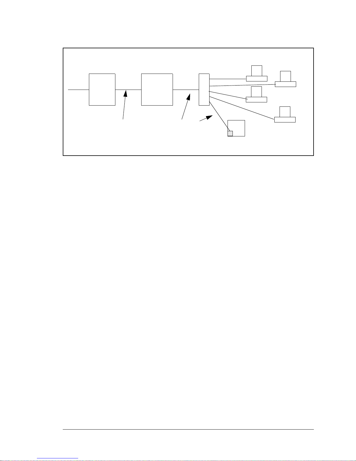
If your system administrator can give you an Ethernet cable along with its IP address, the
Hub(s)
Firewall
Proxy
Server
T1 in
Adapter
Ethernet
Ethernet
Network
RCM3700
System
Typical Corporate Network
netmask and the gateway address, then you may be able to run the sample programs without having to setup a direct connection between your computer and the RCM3700. You
will also need the IP address of the nameserver, the name or IP address of your mail
server, and your domain name for some of the sample programs.
RabbitCore RCM3700 User’s Manual 64
Page 67

6.2.1 IP Addresses Explained
IP (Internet Protocol) addresses are expressed as 4 decimal numbers separated by periods,
for example:
216.103.126.155
10.1.1.6
Each decimal number must be between 0 and 255. The total IP address is a 32-bit number
consisting of the 4 bytes expressed as shown above. A local network uses a group of adja-
cent IP addresses. There are always 2N IP addresses in a local network. The netmask (also
called subnet mask) determines how many IP addresses belong to the local network. The
netmask is also a 32-bit address expressed in the same form as the IP address. An example
netmask is:
255.255.255.0
This netmask has 8 zero bits in the least significant portion, and this means that 28
addresses are a part of the local network. Applied to the IP address above
(216.103.126.155), this netmask would indicate that the following IP addresses belong to
the local network:
216.103.126.0
216.103.126.1
216.103.126.2
etc.
216.103.126.254
216.103.126.255
The lowest and highest address are reserved for special purposes. The lowest address
(216.102.126.0) is used to identify the local network. The highest address
(216.102.126.255) is used as a broadcast address. Usually one other address is used for the
address of the gateway out of the network. This leaves 256 - 3 = 253 available IP
addresses for the example given.
RabbitCore RCM3700 User’s Manual 65
Page 68

6.2.2 How IP Addresses are Used
The actual hardware connection via an Ethernet uses Ethernet adapter addresses (also
called MAC addresses). These are 48-bit addresses and are unique for every Ethernet
adapter manufactured. In order to send a packet to another computer, given the IP address
of the other computer, it is first determined if the packet needs to be sent directly to the
other computer or to the gateway. In either case, there is an Ethernet address on the local
network to which the packet must be sent. A table is maintained to allow the protocol
driver to determine the MAC address corresponding to a particular IP address. If the table
is empty, the MAC address is determined by sending an Ethernet broadcast packet to all
devices on the local network asking the device with the desired IP address to answer with
its MAC address. In this way, the table entry can be filled in. If no device answers, then
the device is nonexistent or inoperative, and the packet cannot be sent.
Some IP address ranges are reserved for use on internal networks, and can be allocated
freely as long as no two internal hosts have the same IP address. These internal IP
addresses are not routed to the Internet, and any internal hosts using one of these reserved
IP addresses cannot communicate on the external Internet without being connected to a
host that has a valid Internet IP address. The host would either translate the data, or it
would act as a proxy.
Each RCM3700 RabbitCore module has its own unique MAC address, which consists of
the prefix 0090C2 followed by a code that is unique to each RCM3700 module. For example, a MAC address might be 0090C2C002C0.
TIP: You can always obtain the MAC address on your board by running the sample pro-
gram DISPLAY_MAC.C from the SAMPLES\TCPIP folder.
RabbitCore RCM3700 User’s Manual 66
Page 69

6.2.3 Dynamically Assigned Internet Addresses
In many instances, devices on a network do not have fixed IP addresses. This is the case
when, for example, you are assigned an IP address dynamically by your dial-up Internet
service provider (ISP) or when you have a device that provides your IP addresses using
the Dynamic Host Configuration Protocol (DHCP). The RCM3700 modules can use such
IP addresses to send and receive packets on the Internet, but you must take into account
that this IP address may only be valid for the duration of the call or for a period of time,
and could be a private IP address that is not directly accessible to others on the Internet.
These addresses can be used to perform some Internet tasks such as sending e-mail or
browsing the Web, but it is more difficult to participate in conversations that originate
elsewhere on the Internet. If you want to find out this dynamically assigned IP address,
under Windows 98 you can run the winipcfg program while you are connected and look
at the interface used to connect to the Internet.
Many networks use IP addresses that are assigned using DHCP. When your computer
comes up, and periodically after that, it requests its networking information from a DHCP
server. The DHCP server may try to give you the same address each time, but a fixed IP
address is usually not guaranteed.
If you are not concerned about accessing the RCM3700 from the Internet, you can place
the RCM3700 on the internal network using an IP address assigned either statically or
through DHCP.
RabbitCore RCM3700 User’s Manual 67
Page 70

6.3 Placing Your Device on the Network
In many corporate settings, users are isolated from the Internet by a firewall and/or a
proxy server. These devices attempt to secure the company from unauthorized network
traffic, and usually work by disallowing traffic that did not originate from inside the network. If you want users on the Internet to communicate with your RCM3700, you have
several options. You can either place the RCM3700 directly on the Internet with a real
Internet address or place it behind the firewall. If you place the RCM3700 behind the firewall, you need to configure the firewall to translate and forward packets from the Internet
to the RCM3700.
RabbitCore RCM3700 User’s Manual 68
Page 71
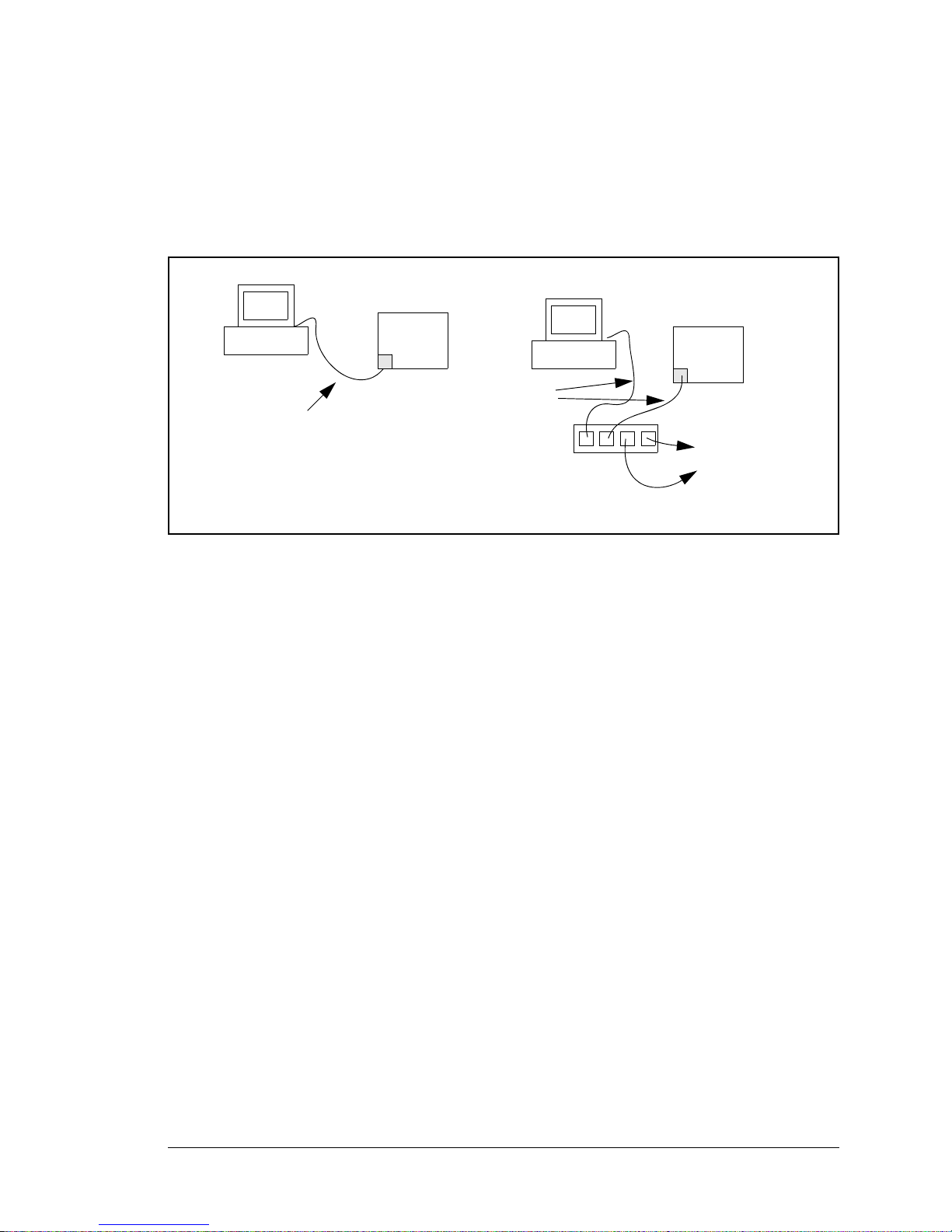
6.4 Running TCP/IP Sample Programs
RCM3700
User’s PC
Ethernet
crossover
cable
Direct Connection
(network of 2 computers)
RCM3700
Hub
Ethernet
cables
To additional
network
elements
Direct Connection Using a Hub
System
System
We have provided a number of sample programs demonstrating various uses of TCP/IP for
networking embedded systems. These programs require you to connect your PC and the
RCM3700 board together on the same network. This network can be a local private network (preferred for initial experimentation and debugging), or a connection via the Internet.
RabbitCore RCM3700 User’s Manual 69
Page 72

6.4.1 How to Set IP Addresses in the Sample Programs
With the introduction of Dynamic C 7.30 we have taken steps to make it easier to run
many of our sample programs. You will see a TCPCONFIG macro. This macro tells
Dynamic C to select your configuration from a list of default configurations. You will
have three choices when you encounter a sample program with the TCPCONFIG macro.
1. You can replace the TCPCONFIG macro with individual MY_IP_ADDRESS, MY_NET-
MASK
, MY_GATEWAY, and MY_NAMESERVER macros in each program.
2. You can leave TCPCONFIG at the usual default of 1, which will set the IP configurations
to 10.10.6.100, the netmask to 255.255.255.0, and the nameserver and gateway
to 10.10.6.1. If you would like to change the default values, for example, to us e an IP
address of 10.1.1.2 for the RCM3700 board, and 10.1.1.1 for your PC, you can edit
the values in the section that directly follows the “General Configuration” comment in
the TCP_CONFIG.LIB library. You will find this library in the LIB\TCPIP directory.
3. You can create a CUSTOM_CONFIG.LIB library and use a TCPCONFIG value greater
than 100. Instructions for doing this are at the beginning of the TCP_CONFIG.LIB
library in the LIB\TCPIP directory.
There are some other “standard” configurations for TCPCONFIG that let you select different features such as DHCP. Their values are documented at the top of the TCP_CON-
FIG.LIB
library in the LIB\TCPIP directory. More information is available in the
Dynamic C TCP/IP User’s Manual.
RabbitCore RCM3700 User’s Manual 70
Page 73
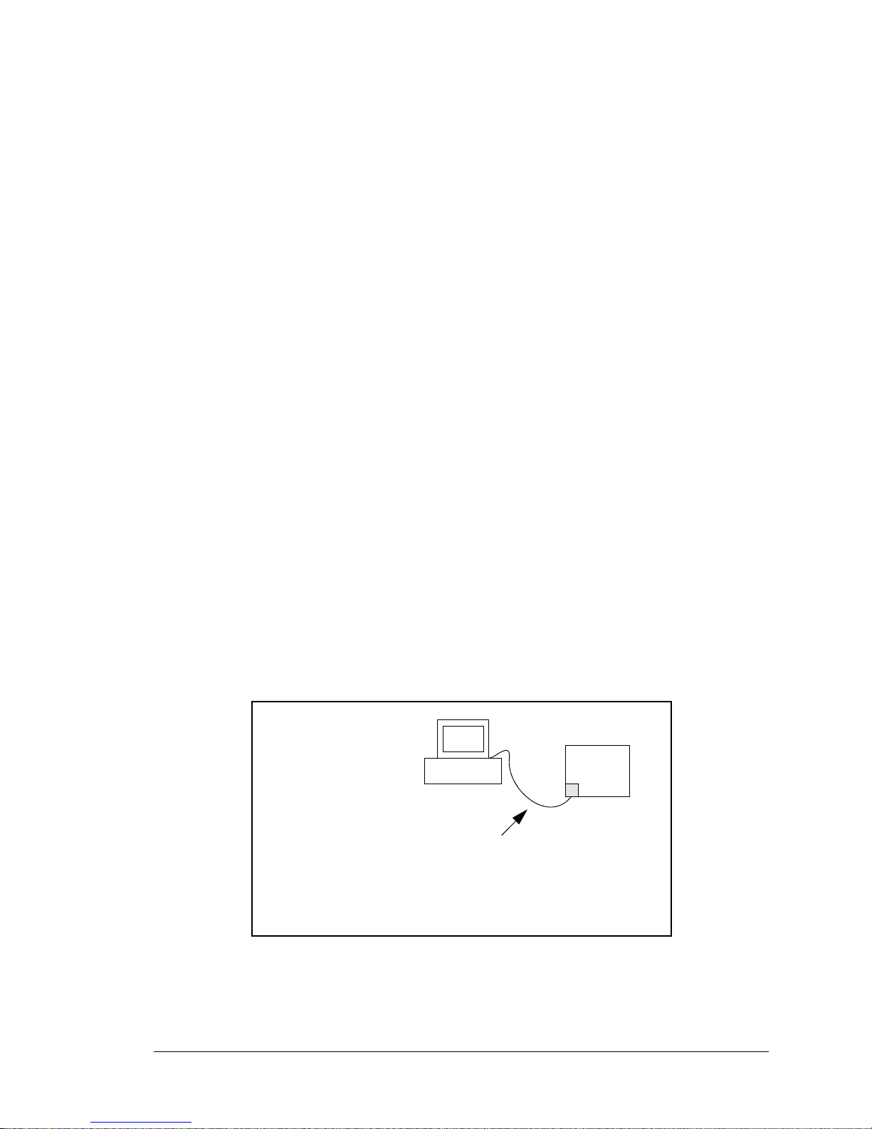
6.4.2 How to Set Up your Computer for Direct Connect
RCM3700
User’s PC
Ethernet
crossover
cable
IP 10.10.6.101
Netmask
255.255.255.0
Direct Connection PC to RCM3700 Board
System
Follow these instructions to set up your PC or notebook. Check with your administrator if
you are unable to change the settings as described here since you may need administrator
privileges. The instructions are specifically for Windows 2000, but the interface is similar
for other versions of Windows.
TIP: If you are using a PC that is already on a network, you will disconnect the PC from
that network to run these sample programs. Write down the existing settings before
changing them to facilitate restoring them when you are finished with the sample programs and reconnect your PC to the network.
1. Go to the control panel (Start > Settings > Control Panel), and then double-click the
Network icon.
2. Select the network interface card used for the Ethernet interface you intend to use (e.g.,
TCP/IP Xircom Credit Card Network Adapter) and click on the “Properties” button.
Depending on which version of Windows your PC is running, you may have to select
the “Local Area Connection” first, and then click on the “Properties” button to bring up
the Ethernet interface dialog. Then “Configure” your interface card for a “10Base-T
Half-Duplex” or an “Auto-Negotiation” connection on the “Advanced” tab.
NOTE: Your network interface card will likely have a different name.
3. Now select the IP Address tab, and check Specify an IP Address, or select TCP /IP and
click on “Properties” to assign an IP address to your computer (this will disable “obtain
an IP address automatically”):
IP Address : 10.10.6.101
Netmask : 255.255.255.0
Default gateway : 10.10.6.1
4. Click <OK> or <Close> to exit the various dialog boxes.
RabbitCore RCM3700 User’s Manual 71
Page 74

6.5 Run the PINGME.C Sample Program
Connect the crossover cable from your computer’s Ethernet port to the RCM3700 board’s
RJ-45 Ethernet connector. Open this sample program from the SAMPLES\TCPIP\ICMP
folder, compile the program, and start it running under Dynamic C. When the program
starts running, the green LINK light on the RCM3700 module should be on to indicate an
Ethernet connection is made. (Note: If the LNK light does not light, you may not be using
a crossover cable, or if you are using a hub perhaps the power is off on the hub.)
The next step is to ping the board from your PC. This can be done by bringing up the MSDOS window and running the pingme program:
ping 10.10.6.100
or by Start > R u n
and typing the entry
ping 10.10.6.100
Notice that the yellow ACT light flashes on the RCM3700 module while the ping is taking
place, and indicates the transfer of data. The ping routine will ping the board four times
and write a summary message on the screen describing the operation.
6.6 Running Additional Sample Programs With Direct Connect
The sample programs discussed here are in the Dynamic C SAMPLES\RCM3700\TCPIP\
and the SAMPLES\RCM3720\TCPIP\ folders.
The program BROWSELED.C demonstrates how to make the RCM3700 board be a Web
server. Two “LEDs” are created on the Web page, along with two buttons to toggle them.
Users can change the status of the lights from the Web browser. The LEDs on the Prototyping Board match the ones on the Web page. As long as you have not modified the
TCPCONFIG 1 macro in the sample program, enter the following server address in your
Web browser to bring up the Web page served by the sample program.
http://10.10.6.100.
Otherwise use the TCP/IP settings you entered in the TCP_CONFIG.LIB library.
The optional LCD/keypad module (see Appendix C) must be plugged in to the RCM3700
Prototyping Board when using this sample program. The sample program
MBOXDEMO.C
implements a W eb server that allows e-mail messages to be entered and then shown on the
LCD/keypad module. The keypad allows the user to scroll within messages, flip to other
e-mails, mark messages as read, and delete e-mails. When a new e-mail arrives, an LED
(on the Prototyping Board and LCD/keypad module) turns on, then turns back off once the
message has been marked as read. A log of all e-mail actions is kept, and can be displayed
in the Web browser. All current e-mails can also be read with the Web browser.
The sample program
flash LEDs DS1 and DS2 on the Prototyping Board when a ping is sent and received.
RabbitCore RCM3700 User’s Manual 72
PINGLED.C demonstrates ICMP by pinging a remote host. It will
Page 75

The sample program SMTP.C allows you to send an e-mail when a switch on the Prototyping Board is pressed. Follow the instructions included with the sample program. LED DS1
on the Prototyping Board will light up when sending e-mail. Note that pin PB7 is connected to both switch S2 and to the external I/O bus on the Prototyping Board, and so
switch S2 should not be used with Ethernet operations.
6.6.1 RabbitWeb Sample Programs
You will need to have the Dynamic C RabbitWeb module installed before you run the
sample programs described in this section. The sample programs can be found in the SAM-
PLES\RCM3700\TCPIP\RABBITWEB
folder.
• BLINKLEDS.C—This program demonstrates a basic example to change the rate at
which the DS1 and DS2 LEDs on the RCM3700 Prototyping Board or the RCM3720
Prototyping Board blink.
• DOORMONITOR.C—The optional LCD/keypad module (see Appendix C) must be plugged
in to the RCM3700 Prototyping Board when using this sample program. This program
demonstrates adding and monitoring passwords entered via the LCD/keypad module.
• HANGMAN_GAME.C—This sample program based on the children's hangman word
guessing game demonstrates some RabbitWeb capabilities using the RCM3720 Prototyping Board.
• LEDS_CHECKBOX.C—This sample program provides a bare-bones sample of using
some RabbitWeb features to control digital I/O using the RCM3720 Prototyping Board.
• SPRINKLER.C—This program demonstrates how to schedule times for the digital out-
puts in a 24-hour period using the RCM3700 Prototyping Board or the RCM3720
Prototyping Board.
• TEMPERATURE.C—This program demonstrates the use of a thermistor with the
RCM3700 Prototyping Board to measure temperature, and it also demonstrates some
simple
#web variable registration along with the authentication features. An e-mail
message will be sent if the current temperature exceeds the minimum or maximum limits set by the user.
Before running this sample program, you will have to install the thermistor included in
the RCM3700 Development Kit at location J7 on the RCM3700 Prototyping Board,
which is connected to analog input THERM_IN7.
RabbitCore RCM3700 User’s Manual 73
Page 76

6.6.2 Secure Sockets Layer (SSL) Sample Programs
You will need to have the Dynamic C SSL module installed before you run the sample
programs described in this section. The sample programs can be found in the SAMPLES\
RCM3700\TCPIP\SSL
folder.
Before running these sample programs, you will have to create an SSL certificate. The
SSL walkthrough in the online documentation for the Dynamic C SSL module explains
how to do this.
• SSL_BROWSELED.C—This program demonstrates a basic controller running a Web
page. T wo “LEDs” are created on the Web page, along with two buttons to toggle them.
Users can change the status of the lights from the Web browser. The LEDs on the Prototyping Board match the ones on the Web page. As long as you have not modified the
TCPCONFIG 1 macro in the sample program, enter the following server address in your
Web browser to bring up the Web page served by the sample program.
http://10.10.6.100
Otherwise use the TCP/IP settings you entered in the TCP_CONFIG.LIB library.
• SSL_MBOXDEMO.C—Implements a Web server that allows e-mail messages to be
entered and then shown on the LCD/keypad module. The keypad allows the user to
scroll within messages, flip to other e-mails, mark messages as read, and delete e-mails.
When a new e-mail arrives, an LED (on the Prototyping Board and LCD/keypad
module) turns on, then turns back off once the message has been marked as read. A log
of all e-mail actions is kept, and can be displayed in the Web browser. All current emails can also be read with the Web browser.
6.6.3 Dynamic C FAT File System, RabbitWeb, and SSL Modules
The Dynamic C FAT File System, RabbitWeb, and Secure Sockets Layer (SSL) modules
have been integrated into a sample program for the RCM3700. The sample program
requires that you have installed the Dynamic C FAT File System, RabbitWeb, and SSL
modules. V isit our Web site at www.rabbit.com or contact your Rabbit sales representative
or authorized distributor for further information on these Dynamic C modules.
NOTE: These sample programs will work only on the RCM3700 and the RCM3720, but
not the RCM3710. The RCM3700 RabbitCore modules do not support the download
manager portion of the sample program.
TIP: Before running any of the sample programs described in this section, you should
look at and run sample programs for the TCP/IP
system, RabbitWeb, SSL, the download manager, and HTTP upload to become more
familiar with their operation.
ZSERVER.LIB library, the FAT file
The INTEGRATION.C sample program in the SAMPLES\RCM3700\Module_Integration
and the
SAMPLES\RCM3720\Module_Integration folders demonstrate the use of the
TCP/IP ZSERVER.LIB library and FAT file system functionality with RabbitWeb
dynamic HTML content, all secured using SSL. The sample program also supports
dynamic updates of both the application and its resources using the Rabbit Download
Manager (DLM) and HTTP upload capability, respectively—note that neither of these
currently supports SSL security.
RabbitCore RCM3700 User’s Manual 74
Page 77

Before you run the INTEGRATION.C sample program, you will first need to format and
partition the serial flash. Find the FMT_DEVICE.C sample program in the Dynamic C
SAMPLES\FileSystem folder. Open this sample program with the File > Open menu,
then compile and run it by pressing F9. FMT_DEVICE.C formats the serial flash for use
with the FAT file system. If the serial flash is already formatted, FMT_DEVICE.C gives
you the option of erasing the serial flash and reformatting it with a single large partition.
This erasure does not check for non-FAT partitions and will destroy all existing partitions.
Next, run the INTEGRATION_FAT_SETUP.C sample program in the Dynamic C
SAMPLES\RCM3700\Module_Integration folder . Open this sample program with the
File > Open menu, then compile and run it by pressing F9. INTEGRATION_FAT_
SETUP.C
will copy some files into the FAT file system via #ximport.
The last step to complete before you can run the INTEGRATION.C sample program is to
create an SSL certificate. The SSL walkthrough in the online documentation for the
Dynamic C SSL module explains how to do this.
Now you are ready to run the INTEGRATION.C sample program in the Dynamic C
SAMPLES\RCM3700\Module_Integration folder . Open this sample program with the
File > Open menu, then compile and run it by pressing F9.
NOTE: Since HTTP upload and the Dynamic C SSL module currently do not work
together, compiling the INTEGRATION.C
warning. Ignore the warning because we are not using HTTP upload over SSL. A
macro (HTTP_UPLOAD_SSL_SUPRESS_WARNING) is available to suppress the
warning message.
sample program will generate a serious
Open a Web browser, and browse to the device using the IP address from the TCP_
CONFIG.LIB
library or the URL you assigned to the device. The humidity monitor will
be displayed in your Web browser. This page is accessible via plain HTTP or over SSLsecured HTTPS. Click on the administrator link to bring up the admin page, which is
secured automatically using SSL with a user name and a password. Use
myadmin for user
name and use myadmin for the password.
The admin page demonstrates some RabbitWeb capabilities and provides access to the
HTTP upload page. Click the upload link to bring up the HTTP upload page, which allows
you to choose new files for both the humidity monitor and the admin page. If your browser
prompts you again for your user name and password, they are the same as before.
Note that the upload page is a static page included in the program flash, and can only be
updated by recompiling and downloading the application. This way, the page is protected
so that you cannot accidentally change it, possibly restricting yourself from performing
future updates. If you wish, you may place the upload page into the FAT file system to
allow the upload page to be updated.
To try out the update capability, click the upload link on the admin page and choose a
simple text file to replace monitor.ztm. Open another browser window and load the
main Web page. You will see that your text file has replaced the humidity monitor. To
RabbitCore RCM3700 User’s Manual 75
Page 78

restore the monitor, go back to the other window, click back to go to the upload page
again, and choose HUMIDITY_MONITOR.ZHTML to replace monitor.ztm, and click
Upload.
When you refresh the page in your browser, you will see that the page has been restored.
You have successfully updated and restored your application's files remotely!
When you are finished with the INTEGRATION.C sample program, you need to follow a
special shutdown procedure before powering off to prevent any possible corruption of the
F AT file system. Press and hold switch S1 on the Prototyping Board until LED DS1 blinks
rapidly to indicate that it is now safe to turn the RCM3700 off. This procedure can be
modified by the user to provide other application-specific shutdown tasks.
6.7 Where Do I Go From Here?
NOTE: If you purchased your RCM3700 through a distributor or through a Rabbit partner,
contact the distributor or partner first for technical support.
If there are any problems at this point:
• Use the Dynamic C Help menu to get further assistance with Dynamic C.
• Check the Rabbit Technical Bulletin Board and forums at www.rabbit.com/support/bb/
and at www.rabbit.com/forums/.
• Use the Technical Support e-mail form at www.rabbit.com/support/.
If the sample programs ran fine, you are now ready to go on.
Additional sample programs are described in the Dynamic C TCP/IP User’s Manual.
Please refer to the Dynamic C TCP/IP User’s Manual to develop your own applications.
An Introduction to TCP/IP provides background information on TCP/IP, and is available
on the CD and on our Web site.
RabbitCore RCM3700 User’s Manual 76
Page 79

APPENDIX A. RCM3700 SPECIFICATIONS
Appendix A provides the specifications for the RCM3700, and
describes the conformal coating.
RabbitCore RCM3700 User’s Manual 77
Page 80
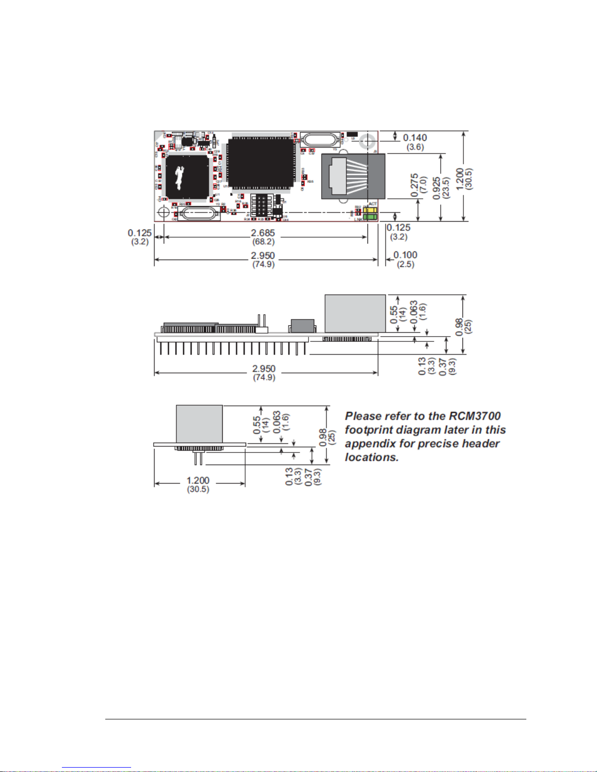
A.1 Electrical and Mechanical Characteristics
Figure A-1 shows the mechanical dimensions for the RCM3700.
NOTE: All measurements are in inches followed by millimeters enclosed in parentheses.
All dimensions have a manufacturing tolerance of ±0.01" (0.2 mm).
The mounting holes shown in Figure A-1 were introduced in 2009. RCM3700 RabbitCore
modules sold before 2009 do not have these mounting holes.
RabbitCore RCM3700 User’s Manual 78
Figure A-1. RCM3700 Dimensions
Page 81
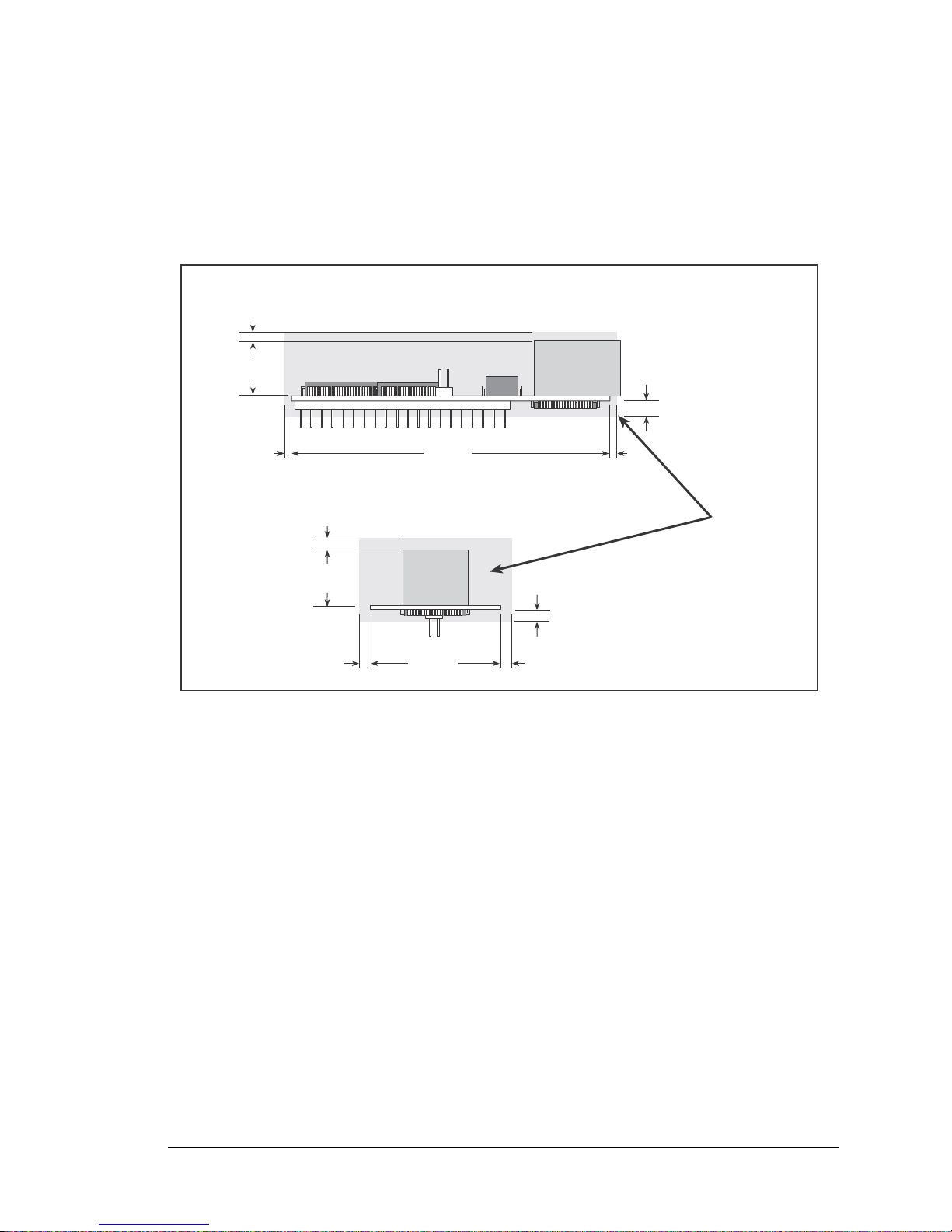
It is recommended that you allow for an “exclusion zone” of 0.04" (1 mm) around the
0.55
(14)
0.55
(14)
Exclusion
Zone
0.04
(1)
0.04
(1)
0.16
(4)
0.16
(4)
0.04
(1)
0.04
(1)
0.04
(1)
0.04
(1)
2.950
(74.9)
1.200
(30.5)
RCM3700 in all directions when the RCM3700 is incorporated into an assembly that
includes other printed circuit boards. An “exclusion zone” of 0.16" (4 mm) is recommended below the RCM3700 when the RCM3700 is plugged into another assembly using
the shortest connectors for header J1. Figure A-2 shows this “exclusion zone.”
RabbitCore RCM3700 User’s Manual 79
Figure A-2. RCM3700 “Exclusion Zone”
Page 82
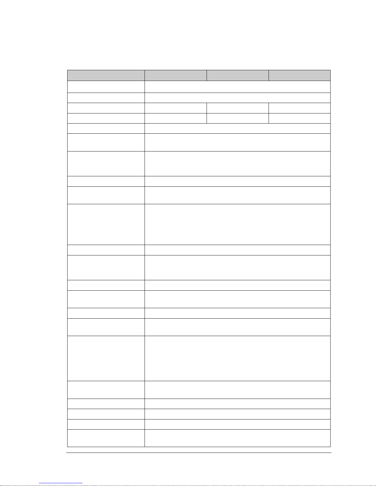
T able A-1 lists the electrical, mechanical, and environmental specifications for the RCM3700.
Table A-1. RabbitCore RCM3700 Specifications
Parameter RCM3700 RCM3710 RCM3720
Microprocessor
Ethernet Port 10/100-compatible with 10Base-T interface, RJ-45, 2 LEDs
Flash Memory 512K 256K 512K
SRAM 512K128K256K
Serial Flash Memory 1Mbyte
Backup Battery
General-Purpose I/O
Additional I/O Reset
External I/O Bus
5 address lines (shared with parallel I/O lines), plus I/O read/write
Four 3.3 V CMOS-compatible ports configurable as:
Low-EMI Rabbit 3000
Connection for user-supplied backup battery
(to support RTC and SRAM)
33 parallel digital I/0 lines:
• 31 configurable I/O
• 2 fixed outputs
Can be configured for 8 data lines and
®
at 22.1 MHz
• 4 asynchronous serial ports (with IrDA) or
Serial Ports
• 3 clocked serial ports (SPI) plus 1 HDLC (with IrDA) or
• 1 clocked serial port (SPI) plus 2 HDLC serial ports (with IrDA)
Serial Rate Maximum asynchronous baud rate = CLK/8
A slave port allows the RCM3700 to be used as an intelligent peripheral
Slave Interface
Real-Time Clock Yes
Timers
Watchdog/Supervisor Yes
Pulse-Width Modulators
Input Capture/
Quadrature Decoder
device slaved to a master processor, which may either be another Rabbit
3000 or any other type of processor
Ten 8-bit timers (6 cascadable, 3 reserved for internal peripherals),
one 10-bit timer with 2 match registers
4 PWM output channels with 10-bit free-running counter
and priority interrupts
2-channel input capture can be used to time input signals from various
port pins
• 1 quadrature decoder unit accepts inputs from external incremental
encoder modules or
• 1 quadrature decoder unit shared with 2 PWM channels
Power
Operating Temperature –40°C to +70°C
Humidity 5% to 95%, noncondensing
Connectors One 2 x 20, 0.1" pitch
Board Size
100 mA @ 22.1 MHz, 5 V; 78 mA @ 11.05 MHz, 5 V
4.75–5.25 V DC
1.20" × 2.95" × 0.98"
(30 mm × 75 mm × 25 mm)
RabbitCore RCM3700 User’s Manual 80
Page 83
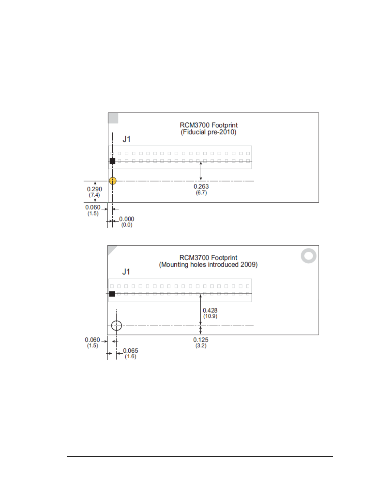
A.1.1 Headers
The RCM3700 uses one header at J1 for physical connection to other boards. J1 is a
2 × 20 SMT header with a 0.1" pin spacing.
Figure A-3 shows the layout of another board for the RCM3700 to be plugged into. These
values are relative to the designated fiducial or mounting hole (reference point).
RabbitCore RCM3700 User’s Manual 81
Figure A-3. User Board Footprint for RCM3700
Page 84
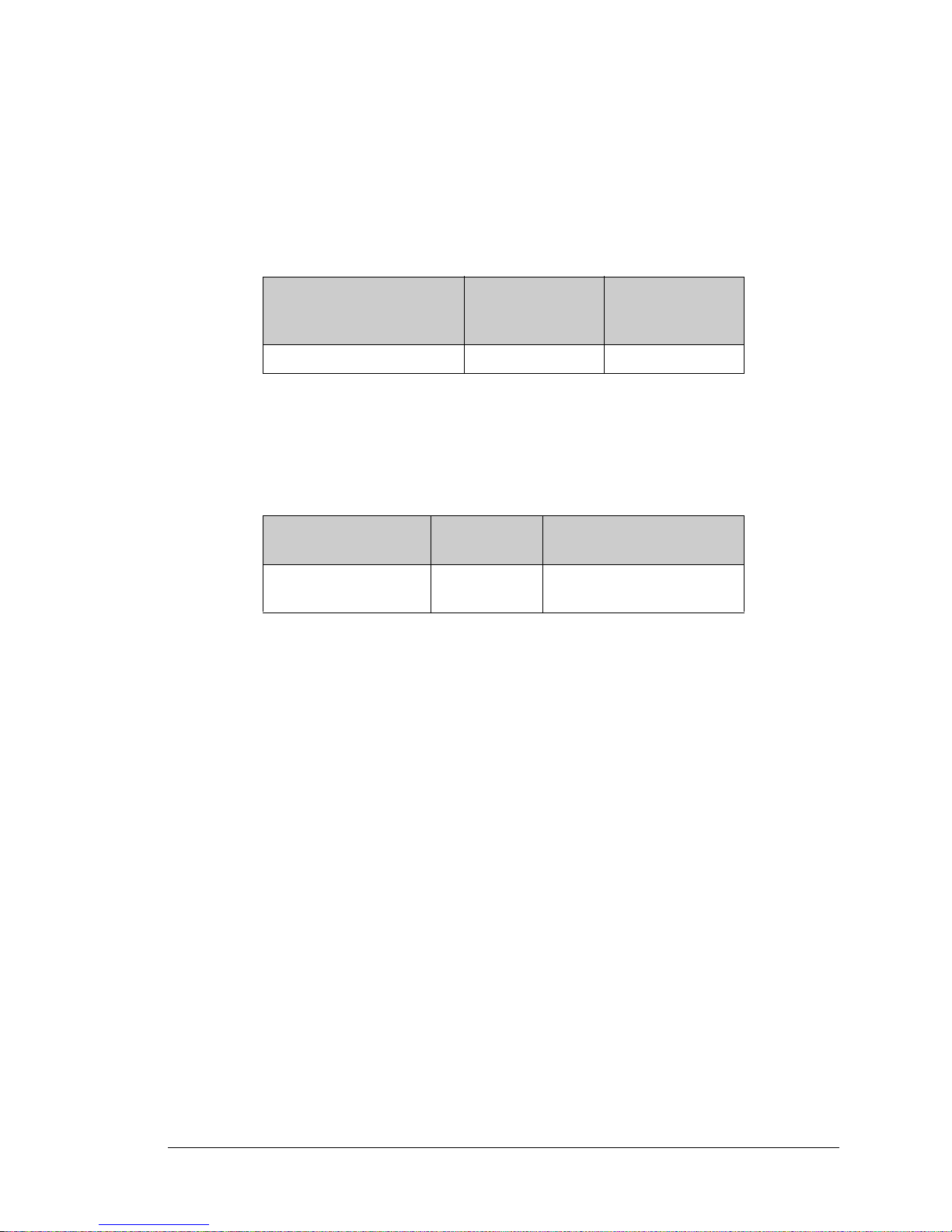
A.2 Bus Loading
You must pay careful attention to bus loading when designing an interface to the
RCM3700. This section provides bus loading information for external devices.
Table A-2 lists the capacitance for the various RCM3700 I/O ports.
Table A-2. Capacitance of Rabbit 3000 I/O Ports
Input
I/O Ports
Parallel Ports A to G 12 14
Capacitance
(pF)
Output
Capacitance
(pF)
Table A-3 lists the external capacitive bus loading for the various RCM3700 output ports.
Be sure to add the loads for the devices you are using in your custom system and verify
that they do not exceed the values in Table A-3.
Table A-3. External Capacitive Bus Loading -40°C to +85°C
Output Port
All I/O lines with clock
doubler enabled
Clock Speed
(MHz)
22.1 100
Maximum External
Capacitive Loading (pF)
RabbitCore RCM3700 User’s Manual 82
Page 85
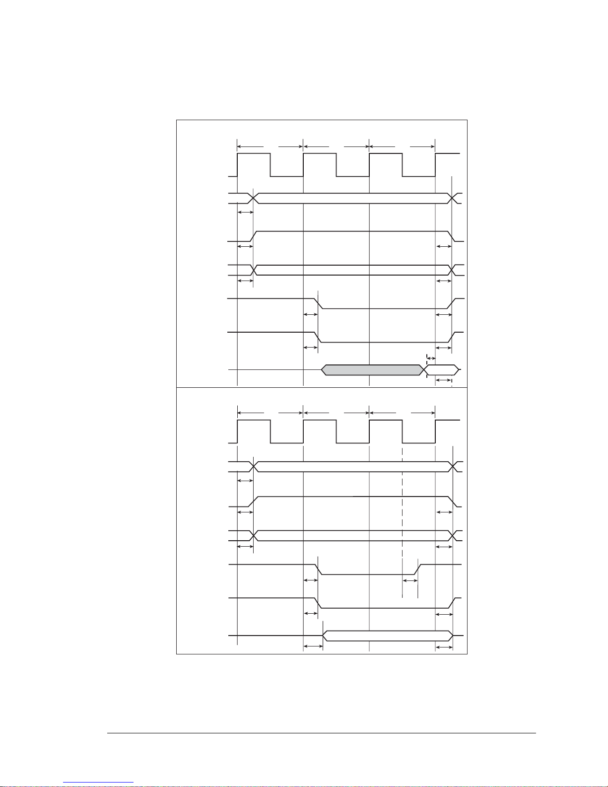
Figure A-4 shows a typical timing diagram for the Rabbit 3000 microprocessor external
T
adr
T
adr
External I/O Read (one programmed wait state)
CLK
A[15:0]
External I/O Write (one programmed wait state)
CLK
A[15:0]
/IORD
valid
T1
Tw
T1
Tw
T2
valid
T2
/BUFEN
/IOCSx
/IOWR
/BUFEN
D[7:0]
valid
T
setup
T
hold
/CSx
/IOCSx
T
CSx
T
IOCSx
T
IORD
T
BUFEN
T
CSx
T
IOCSx
T
IORD
T
BUFEN
valid
D[7:0]
/CSx
T
CSx
T
IOCSx
T
IOWR
T
CSx
T
IOCSx
T
IOWR
T
BUFEN
T
BUFEN
T
DHZV
T
DVHZ
I/O read and write cycles.
RabbitCore RCM3700 User’s Manual 83
NOTE: /IOCSx can be programmed to be active low (default) or active high.
Figure A-4. I/O Read and Write Cycles—No Extra Wait States
Page 86
Table A-4 lists the delays in gross memory access time.
Table A-4. Data and Clock Delays VIN ±10%, Temp, -40°C–+85°C (maximum)
Clock to Address Output Delay
(ns)
VIN
30 pF 60 pF 90 pF
3.3 V 6 8 11 1 3/4.5 4.5/9
Data Setup
Time Delay
(ns)
Spectrum Spreader Delay
(ns)
Normal
no dbl/dbl
Strong
no dbl/dbl
The measurements are taken at the 50% points under the following conditions.
• T = -40°C to 85°C, V = VDD ±10%
• Internal clock to nonloaded CLK pin delay 1 ns @ 85°C/3.0 V
The clock to address output delays are similar, and apply to the following delays.
• T
• T
• T
• T
• T
, the clock to address delay
adr
, the clock to memory chip select delay
CSx
, the clock to I/O chip select delay
IOCSx
, the clock to I/O read strobe delay
IORD
, the clock to I/O write strobe delay
IOWR
• T
BUFEN
The data setup time delays are similar for both T
, the clock to I/O buffer enable delay
setup
and T
hold
.
When the spectrum spreader is enabled with the clock doubler, every other clock cycle is
shortened (sometimes lengthened) by a maximum amount given in the table above. The
shortening takes place by shortening the high part of the clock. If the doubler is not
enabled, then every clock is shortened during the low part of the clock period. The maximum shortening for a pair of clocks combined is shown in the table.
Technical Note TN227, Interfacing External I/O with Rabbit 2000/3000 Designs, contains suggestions for interfacing I/O devices to the Rabbit 3000 microprocessors.
RabbitCore RCM3700 User’s Manual 84
Page 87
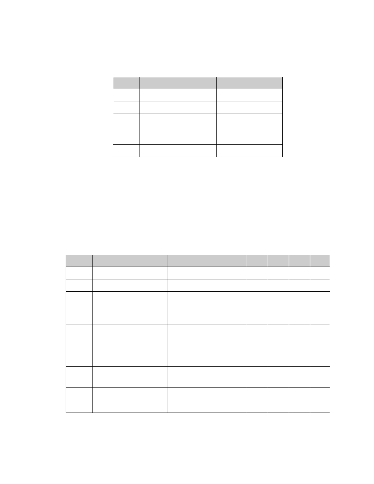
A.3 Rabbit 3000 DC Characteristics
Table A-5. Rabbit 3000 Absolute Maximum Ratings
Symbol Parameter Maximum Rating
T
Operating Temperature -55° to +85°C
A
T
Storage Temperature -65° to +150°C
S
Maximum Input Voltage:
+ 0.5 V
• Oscillator Buffer Input
• 5-V-tolerant I/O
V
Maximum Operating Voltage 3.6 V
DD
V
DD
5.5 V
Stresses beyond those listed in Table A-5 may cause permanent damage. The ratings are
stress ratings only, and functional operation of the Rabbit 3000 chip at these or any other
conditions beyond those indicated in this section is not implied. Exposure to the absolute
maximum rating conditions for extended periods may affect the reliability of the Rabbit
3000 chip.
Table A-6 outlines the DC characteristics for the Rabbit 3000 at 3.3 V over the recommended operating temperature range from TA = –55°C to +85°C, VDD = 3.0 V to 3.6 V.
Table A-6. 3.3 Volt DC Characteristics
Symbol Parameter Test Conditions Min Typ Max Units
V
V
V
V
V
I
I
I
Supply Voltage 3.0 3.3 3.6 V
DD
High-Level Input Voltage 2.0 V
IH
Low-Level Input Voltage 0.8 V
IL
I
High-Level Output Voltage
OH
Low-Level Output Vo ltage
OL
High-Level Input Current
IH
(absolute worst case, all buffers)
Low-Level Input Current
IL
(absolute worst case, all buffers)
High-Impedance State
Output Current
OZ
(absolute worst case, all buffers)
= 6.8 mA,
OH
= VDD (min)
V
DD
I
= 6.8 mA,
OL
= VDD (min)
V
DD
VIN = VDD,
V
= VDD (max)
DD
VIN = VSS,
= VDD (max)
V
DD
VIN = VDD or VSS,
V
= VDD (max), no pull-up
DD
0.7 x
V
DD
-10 µA
-10 10 µA
V
0.4 V
10 µA
RabbitCore RCM3700 User’s Manual 85
Page 88
A.4 I/O Buffer Sourcing and Sinking Limit
Unless otherwise specified, the Rabbit I/O buffers are capable of sourcing and sinking
6.8 mA of current per pin at full AC switching speed. Full AC switching assumes a
22.1 MHz CPU clock and capacitive loading on address and data lines of less than 100 pF
per pin. The absolute maximum operating voltage on all I/O is 5.5 V.
Table A-7 shows the AC and DC output drive limits of the parallel I/O buffers when the
Rabbit 3000 is used in the RCM3700.
Table A-7. I/O Buffer Sourcing and Sinking Capability
Output Drive (Full AC Switching)
Pin Name
All data, address, and I/O
lines with clock doubler
enabled
Sourcing/Sinking
(mA)
Sourcing Sinking
6.8 6.8
Under certain conditions, you can exceed the limits outlined in Table A-7. See the Rabbit
3000 Microprocessor User’s Manual for additional information.
Limits
RabbitCore RCM3700 User’s Manual 86
Page 89
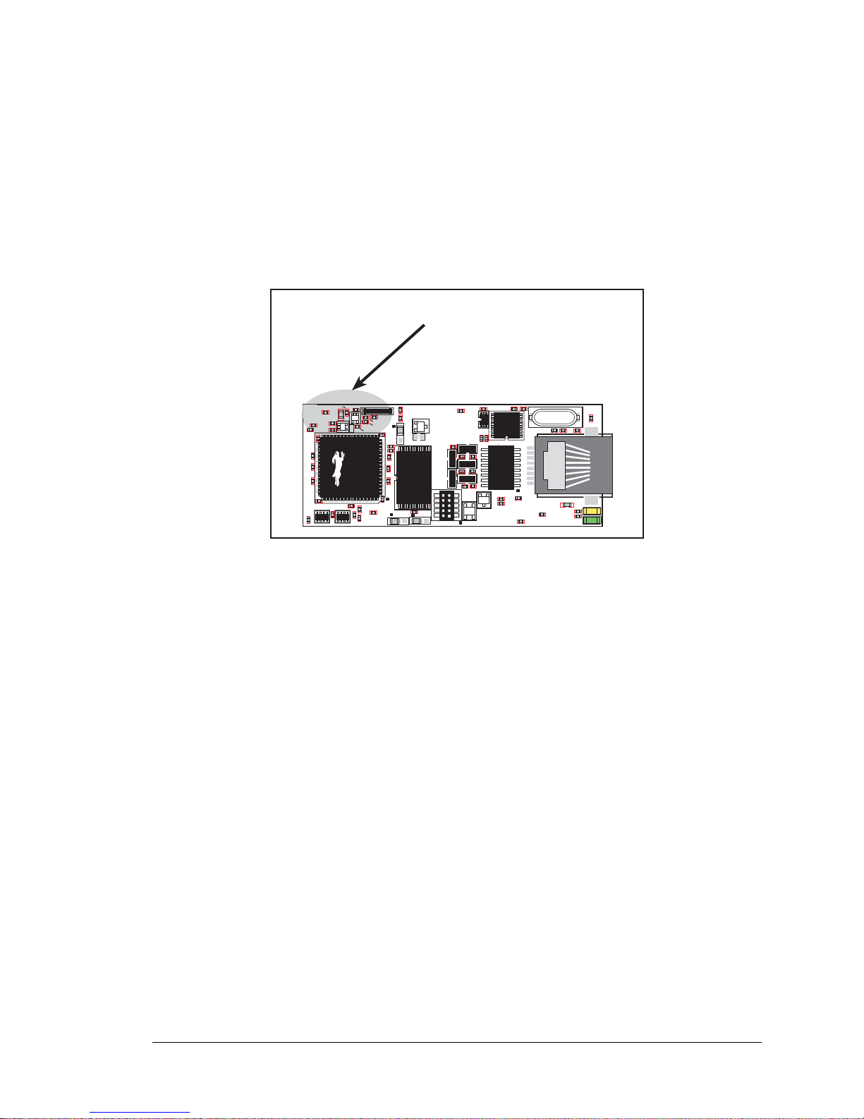
A.5 Conformal Coating
Conformally coated
area
R24
R2
C18
C34
RP1
RP2
R18
R36
C35
C19
C26
C27
C28
R15
R16
C36
C39
R13
U1
C25
JP1
C7
JP3
J2
C33
C32
C30
C31
C15
C17
C20
C38
C41
U4
R6
R11
C37
R4 R5
U5
C29
JP2
Y1
C40
C10
Q1
R7
C49
L2
L1
C14
C12
C22
U8
C23
Y3
C57
R31
C58
R29
DS2
R32
R30
DS1
J3
R34
C16
R28
T1
C24
C21
D1
U6
C53
R26
U3
R33
C8
U11
L4
L3
C54 C55
L6
R27
The areas around the 32 kHz real-time clock crystal oscillator on RCM3700 RabbitCore
modules without mounting holes have had the Dow Corning silicone-based 1-2620 conformal coating applied. The conformally coated area is shown in Figure A-5. The conformal coating protects these high-impedance circuits from the effects of moisture and
contaminants over time. The new design used on RCM3700 RabbitCore modules with
mounting holes do not need a conformal coating.
Figure A-5. RCM3700 Areas Receiving Conformal Coating
Any components in the conformally coated area may be replaced using standard soldering
procedures for surface-mounted components. A new conformal coating should then be
applied to offer continuing protection against the effects of moisture and contaminants.
NOTE: For more information on conformal coatings, refer to Technical Note 303, Con-
formal Coatings.
RabbitCore RCM3700 User’s Manual 87
Page 90

A.6 Jumper Configurations
Figure A-6 shows the header locations used to configure the various RCM3700 options
via jumpers.
Figure A-6. Location of RCM3700 Configurable Positions
RabbitCore RCM3700 User’s Manual 88
Page 91
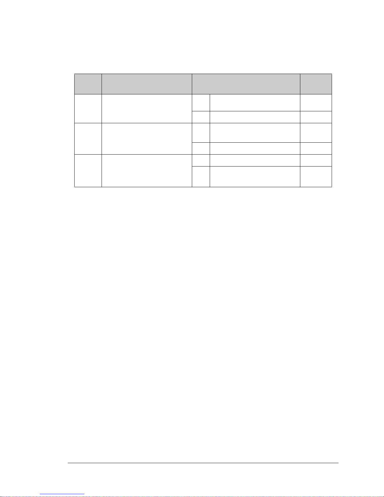
Table A-8 lists the configuration options.
Table A-8. RCM3700 Jumper Configurations
Header Description Pins Connected
1–2 Normal Mode
JP1 Flash Memory Bank Select
2–3 Bank Mode
1–2 128K–256K
JP2 SRAM Size
2–3 512K RCM3700
1–2 256K RCM3710
JP3 Flash Memory Size
2–3 512K
NOTE: The jumper connections are made using 0 surface-mounted resistors.
Factory
Default
×
RCM3710
RCM3720
RCM3700
RCM3720
RabbitCore RCM3700 User’s Manual 89
Page 92

APPENDIX B. PROTOTYPING BOARD
Two different Prototyping Boards are available for the
RCM3700 series of RabbitCore modules. The RCM3700 Prototyping Board has power-supply connections and also provides
some basic I/O peripherals (RS-232, RS-485, A/D converter,
IrDA transceiver, LEDs, and switches), as well as a prototyping
area for more advanced hardware development. The RCM3720
Prototyping Board was designed specifically for the Ethernet
Connection Kit, and only has the power-supply connections,
prototyping area, LEDs, switches, and space for an optional
RS-232 chip to be installed.
Either Prototyping Board may be used with the full line of
RCM3700 RabbitCore modules. Appendix B describes the features and accessories for the two prototyping boards.
RabbitCore RCM3700 User’s Manual 90
Page 93

RCM3700
+V
/RESET
LDE0
LED2
LED4
LED6
GND
+BKLT
/CS
LED1
LED3
LED5
GND
GND
A2
A1
D1D3D5
D7
GND
A3A1D0D2D4D6GND
+BKLT
/CS
LED1
LED3
LED5
GND
GND
A2
A0
D1D3D5
D7
L2
C1
C2
IR1
R1
R2
R3
R4
Rx
Tx
R5
R6
C3
R9
R7
R8
JP1
J1
+485
GND
485
JP2
R12
R11
U3
C4
C7
C8
C10
R13
C11
U4
C5
C6
C9
J2
GND
/IORD
PB5
PB3
PA0
PA6
PB0
/RES
+5V
PF4
PF6
PC1/PG2
PC0_TXD
PE5
PE1
PG7_RXE
PD4
VBAT
PA4 PA2
/IOWR
PE7
PB4
PB2
PA1
PA3
PA5
PA7
PB7
PF0
PF1
PF5
PF7
PE4
PE0
PD5
PG6
TXE
PC2
TXC
PC3/
PG3
GND
RXC TXC RXE
GND
NC
U1
C12
C13
C15
C14
L1
C17
U2
C18
U6
R14
D1
C19
D2
J4
DCIN
+3.3V
GND
+5V
+5V
GND
+3.3V
LCD1JB
LCD1JC
LCD1JA
U5
C16
R15
BT1
GND
TXD
RXD
TXE
GND
TCM_SMT_SOCKET
+5V
VBAT
PD5
/IORD
PG6_TXE
PE0
PE4
PE7
PC2_TXC
PC0_TXD
PF6
PF4
PB5
PB3
PB0
PF1
PA1
PA3
PA5
PA7
J5
GND
R16
GND
/RES
PD4
/IOWR
PE1
PE5
PC3/PG3
PF7
PF5
PB7
PB4
PB2
PF0
PA0
PA2
PA4
PA6
PG7
RXE
PC1/
PG2
C22
C26
R21
R18
C20
R19
C21
R20
R22
JP4
1
2
RP1
CX1 CX2
CX3
CX4
CX5
CX6
CX7
CX8
CX9
CX10CX11
UX2
UX1
U8
R23
C24 C25
C23
U7
C27
R25
R24
C28
R26
R27
R28
R29
JP8
R30 R31 R32
R33
R34
R35
R36
C35
R43
C29
J7
THERMISTOR
R37
J8
VREF
AGND
R44
THERM_IN
AIN
06050403020100
AIN
AGND
R38
C30
C31
C32
C33
C34
R39 R40
R41 R42
R48
DS1
DS2
R45
R49
R46
DS3
R47
S3
S2S1
CONVERT
JP5
JP6
JP7
NC
NCNCNC
NC
NC
+V
/RSTETLED0
LED2
LED4
LED6
GNDA3A1D0D2D4D6
RCM36/37XX SERIES
PROTOTYPING BOARD
RESET
Power
Input
Power
LED
Reset
Switch
User
LEDs
RCM3700 Module
Extension Header
+5 V, 3.3 V, and
GND Buses
RCM3700
Module
Connector
User
Switches
SMT Prototyping
Area
LCD/Keypad
Module
Connections
IRDA
Transceiver
Through-Hole
Prototyping Area
C53
RS-485
RS-232
Header
Analog
Inputs
Analog
Reference
Convert
Ground
Backup
Battery
B.1 RCM3700 Prototyping Board
The RCM3700 Prototyping Board included in the RCM3700 Development Kit makes it
easy to connect an RCM3700 module to a power supply and a PC workstation for development. It also provides some basic I/O peripherals (RS-232, RS-485, A/D converter,
IrDA transceiver, LEDs, and switches), as well as a prototyping area for more advanced
hardware development.
For the most basic level of evaluation and development, the RCM3700 Prototyping Board
can be used without modification.
As you progress to more sophisticated experimentation and hardware development, modifications and additions can be made to the board without modifying or damaging the
RCM3700 module itself.
The RCM3700 Prototyping Board is shown below in Figure B-1, with its main features
identified.
RabbitCore RCM3700 User’s Manual 91
Figure B-1. RCM3700 Prototyping Board
Page 94

B.1.1 Features
• Power Connection—A 3-pin header is provided for connection to the power supply.
Note that the 3-pin header is symmetrical, with both outer pins connected to ground and
the center pin connected to the raw DCIN input. The cable of the AC adapter provided
with the North American version of the Development Kit ends in a plug that connects
to the power-supply header, and can be connected to the 3-pin header in either orientation. A similar header plug leading to bare leads is provided for overseas customers.
Users providing their own power supply should ensure that it delivers 7.5–30 V DC at
500 mA. The voltage regulators will get warm while in use.
• Regulated Power Supply—The raw DC voltage provided at the POWER IN powerinput jack is routed to a 5 V switching voltage regulator, then to a separate 3.3 V linear
regulator. The regulators provide stable power to the RCM3700 module and the Prototyping Board.
• Power LED—The power LED lights whenever power is connected to the Prototyping
Board.
• Reset Switch—A momentary-contact, normally open switch is connected directly to the
RCM3700’s /RESET_IN pin. Pressing the switch forces a hardware reset of the system.
• I/O Switches and LEDs—Two momentary-contact, normally open switches are connected to the PF4 and PB7 pins of the RCM3700 module and may be read as inputs by
sample applications.
RCM3700
Two LEDs are connected to the PF6 and PF7 pins of the RCM3700 module, and may
be driven as output indicators by sample applications.
• Prototyping Area—A generous prototyping area has been provided for the installation
of through-hole components. +3.3 V, +5 V, and Ground buses run at both edges of this
area. Several areas for surface-mount devices are also available. (Note that there are
SMT device pads on both top and bottom of the Prototyping Board.) Each SMT pad is
connected to a hole designed to accept a 30 AWG solid wire or wire-wrap wire.
LCD/Keypad Module—Rabbit’s LCD/keypad module may be plugged in directly to
•
headers LCD1JA, LCD1JB, and LCD1JC. The signals on headers LCD1JB and
LCD1JC will be available only if the LCD/keypad module is plugged in to header
LCD1JA. Appendix C provides complete information for mounting and using the
LCD/keypad module.
• Module Extension Headers—The complete non-analog pin set of the RCM3700
module is duplicated at header J3. Developers can solder wires directly into the appropriate holes, or, for more flexible development, a 2 × 20 header strip with a 0.1" pitch
can be soldered into place. See Figure B-4 for the header pinouts.
•
Analog I/O Shrouded Headers—The complete analog pin set of the RCM3700
Prototyping Board is available on shrouded headers J8 and J9. See Figure B-4 for the
header pinouts.
RabbitCore RCM3700 User’s Manual 92
Page 95

RCM3700
• RS-232—Three 3-wire serial ports or one 5-wire RS-232 serial port and one 3-wire
serial port are available on the Prototyping Board at header J2. A jumper on header JP2
is used to select the drivers for Serial Port E, which can be set either as a 3-wire RS-232
serial port or as an RS-485 serial port. Serial Ports C and D are not available while the
IrDA transceiver is in use.
A 10-pin 0.1-inch spacing header strip is installed at J2 allows you to connect a ribbon
cable that leads to a standard DE-9 serial connector.
• RS-485—One RS-485 serial port is available on the Prototyping Board at shrouded
header J1. A 3-pin shrouded header is installed at J1. A jumper on header JP2 enables
the RS-485 output for Serial Port E.
• IrDA—An infrared transceiver is included on the Prototyping Board, and is capable of
handling link distances up to 1.5 m. The IrDA uses Serial Port F—Serial Ports C and D
are unavailable while Serial Port F is in use.
• Backup Battery—A 2032 lithium-ion battery rated at 3.0 V, 220 mA·h, provides
battery backup for the RCM3700 SRAM and real-time clock.
RabbitCore RCM3700 User’s Manual 93
Page 96
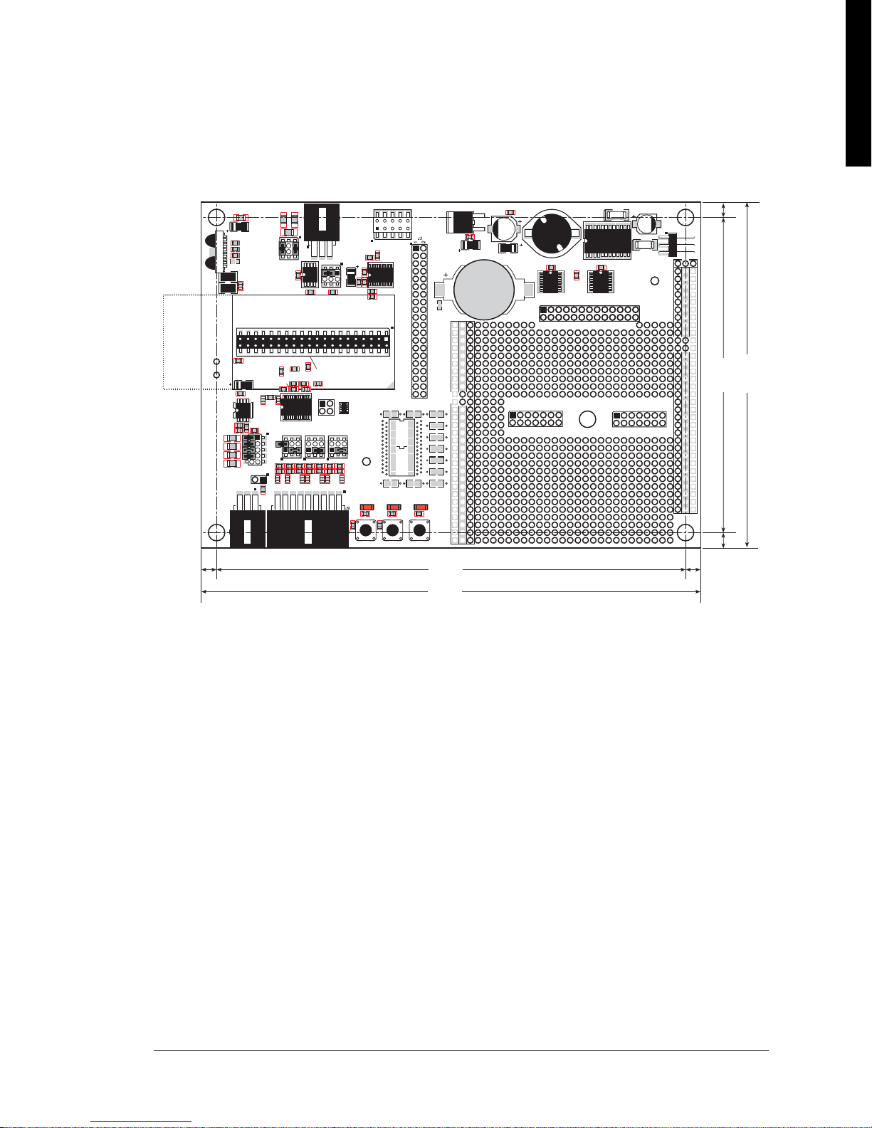
B.1.2 Mechanical Dimensions and Layout
+V
/RESET
LDE0
LED2
LED4
LED6
GND
+BKLT
/CS
LED1
LED3
LED5
GND
GND
A2
A1
D1D3D5
D7
GND
A3A1D0D2D4D6GND
+BKLT
/CS
LED1
LED3
LED5
GND
GND
A2
A0
D1D3D5
D7
L2
C1
C2
IR1
R1
R2
R3
R4
Rx
Tx
R5
R6
C3
R9
R7
R8
JP1
J1
+485
GND
485
JP2
R12
R11
U3
C4
C7
C8
C10
R13
C11
U4
C5
C6
C9
J2
GND
/IORD
PB5
PB3
PA0
PA6
PB0
/RES
+5V
PF4
PF6
PC1/PG2
PC0_TXD
PE5
PE1
PG7_RXE
PD4
VBAT
PA4 PA2
/IOWR
PE7
PB4
PB2
PA1
PA3
PA5
PA7
PB7
PF0
PF1
PF5
PF7
PE4
PE0
PD5
PG6
TXE
PC2
TXC
PC3/
PG3
GND
RXC TXC RXE
GND
NC
U1
C12
C13
C15
C14
L1
C17
U2
C18
U6
R14
D1
C19
D2
J4
DCIN
+3.3V
GND
+5V
+5V
GND
+3.3V
LCD1JB
LCD1JC
LCD1JA
U5
C16
R15
BT1
GND
TXD
RXD
TXE
GND
TCM_SMT_SOCKET
+5V
VBAT
PD5
/IORD
PG6_TXE
PE0
PE4
PE7
PC2_TXC
PC0_TXD
PF6
PF4
PB5
PB3
PB0
PF1
PA1
PA3
PA5
PA7
J5
GND
R16
GND
/RES
PD4
/IOWR
PE1
PE5
PC3/PG3
PF7
PF5
PB7
PB4
PB2
PF0
PA0
PA2
PA4
PA6
PG7
RXE
PC1/
PG2
C22
C26
R21
R18
C20
R19
C21
R20
R22
JP4
1
2
RP1
CX1 CX2
CX3
CX4
CX5
CX6
CX7
CX8
CX9
CX10CX11
UX2
UX1
U8
R23
C24 C25
C23
U7
C27
R25
R24
C28
R26
R27
R28
R29
JP8
R30 R31 R32
R33
R34
R35
R36
C35
R43
C29
J7
THERMISTOR
R37
J8
VREF
AGND
R44
THERM_IN
AIN
06050403020100
AIN
AGND
R38
C30
C31
C32
C33
C34
R39 R40
R41 R42
R48
DS1
DS2
R45
R49
R46
DS3
R47
S3
S2S1
CONVERT
JP5
JP6
JP7
NC
NC
NC
NC
NC
NC
+V
/RSTETLED0
LED2
LED4
LED6
GNDA3A1D0D2D4D6
RCM36/37XX SERIES
PROTOTYPING BOARD
RESET
6.50
(165)
4.50
(114)
6.10
(155)
0.20
(5)
0.20
(5)
4.10
(104)
0.20
(5)
0.20
(5)
Figure B-2 shows the mechanical dimensions and layout for the RCM3700 Prototyping Board.
RCM3700
Figure B-2. RCM3700 Prototyping Board Dimensions
RabbitCore RCM3700 User’s Manual 94
Page 97
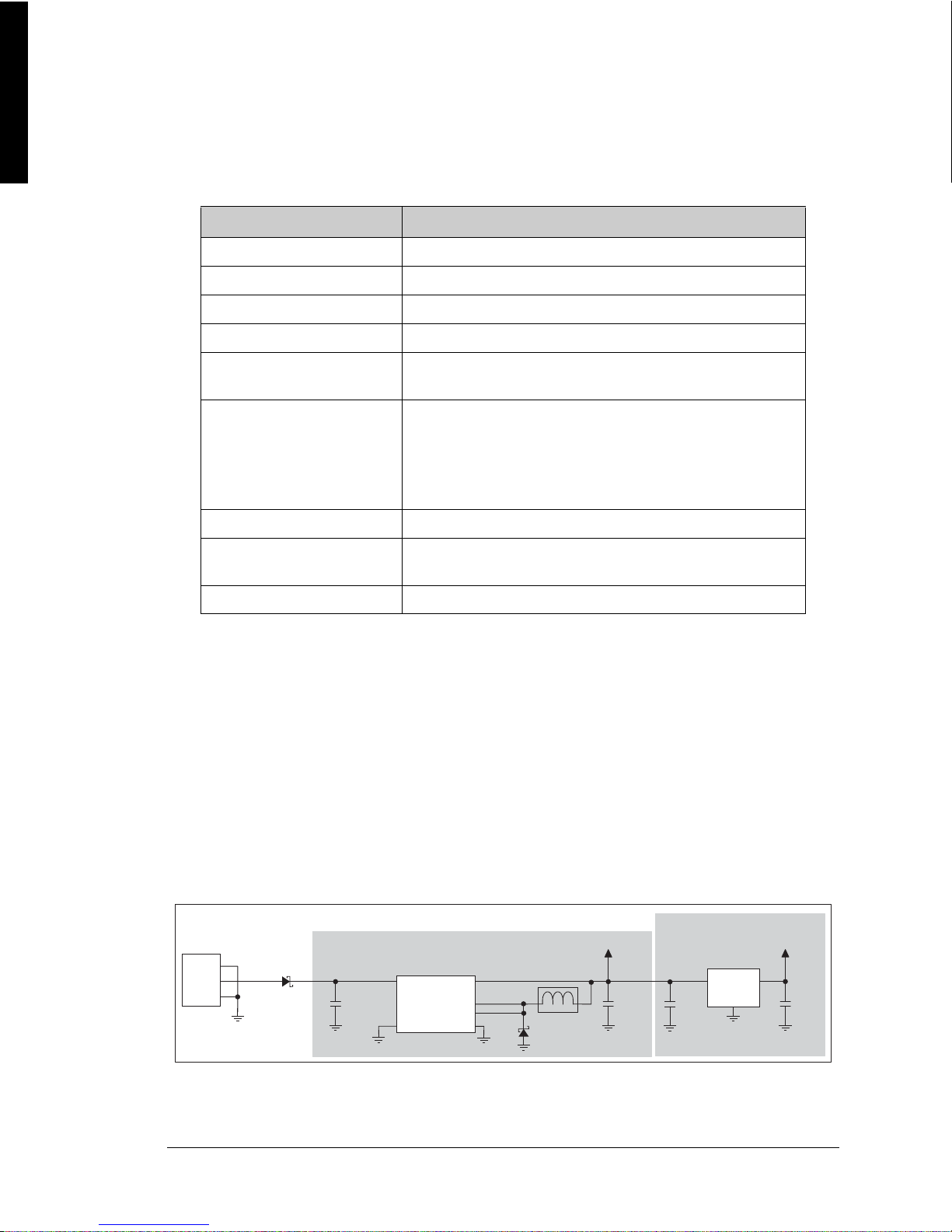
RCM3700
LINEAR POWER
REGULATOR
POWER
IN
J4
10 µF
LM 1117
U1
+3.3 V
3
1
2
1
2
3
1N5819
D2
47 µF
330 µF
+5 V
L1
C19
330 µH
D1
1N5819
SWITCHING POWER REGULATOR
DCIN
U2
LM2575
10 µF
Table B-1 lists the electrical, mechanical, and environmental specifications for the
RCM3700 Prototyping Board.
Table B-1. RCM3700 Prototyping Board Specifications
Parameter Specification
Board Size 4.50" × 6.50" × 0.75" (114 mm × 165 mm × 19 mm)
Operating Temperature –20°C to +60°C
Humidity 5% to 95%, noncondensing
Input Voltage 7.5 V to 30 V DC
Maximum Current Draw
(including user-added circuits)
800 mA max. for +3.3 V supply,
1 A total +3.3 V and +5 V combined
8-channel ADS7870 with programmable gain configurable for
11-bit single-ended, 12-bit differential, and 4–20 mA inputs
A/D Converter
• Input impedance 6–7 M
• A/D conversion time (including 120 µs raw count and
Dynamic C) 180 µs
IrDA Transceiver HSDL-3602, link distances up to 1.5 m
Prototyping Area
2.5" × 3" (64 mm × 76 mm) throughhole, 0.1" spacing,
additional space for SMT components
Standoffs/Spacers 5, accept 4-40 × 1/2 screws
B.1.3 Power Supply
The RCM3700 requires a regulated 4.75 V to 5.25 V DC power source to operate.
Depending on the amount of current required by the application, different regulators can
be used to supply this voltage.
The RCM3700 Prototyping Board has an onboard +5 V switching power regulator from
which a +3.3 V linear regulator draws its supply. Thus both +5 V and +3.3 V are available
on the RCM3700 Prototyping Board.
The RCM3700 Prototyping Board itself is protected against reverse polarity by a Shottky
diode at D2 as shown in Figure B-3.
RabbitCore RCM3700 User’s Manual 95
Figure B-3. RCM3700 Prototyping Board Power Supply
Page 98
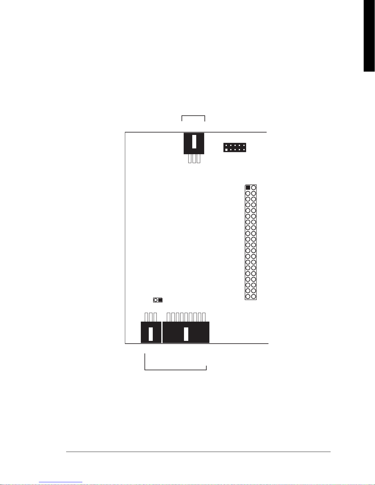
B.1.4 Using the RCM3700 Prototyping Board
J2
GND
TxD
RxD
TxE
GND
GND
RxC
TxC
RxE
J9
J1
J7
GND
/IOWR
PE7
PB4
PB2
PA1
PA3
PA5
PA7
PB7
PF0
PF1
PF5
PF7
PC3/PG3
PC2_TxC
PE4
PE0
PG6_TxE
PD5
GND
/IORD
PB5
PB3
PA0
PA2
PA4
PA6
PB0
/RES
+5 V
PF4
PF6
PC1/PG2
PC0_TxD
PE5
PE1
PG7_RxE
PD4
VBAT
J3
J3
RS-485
GND
RS-485+
RCM3700
Non-Analog
Signals
RS-232
J8
Thermistor
VREF
CONVERT
ANALOG_GND
THERM_IN7
ADC_IN6
ADC_IN5
ADC_IN4
ADC_IN3
ADC_IN2
ADC_IN1
THERM_IN0
ANALOG_GND
Analog
I/O
RS-485
The RCM3700 Prototyping Board is actually both a demonstration board and a prototyping board. As a demonstration board, it can be used to demonstrate the functionality of the
RCM3700
right out of the box without any modifications.
Figure B-4 shows the RCM3700 Prototyping Board pinouts.
RCM3700
Figure B-4. RCM3700 Prototyping Board Pinout
RabbitCore RCM3700 User’s Manual 96
Page 99

RCM3700
The RCM3700 Prototyping Board comes with the basic components necessary to demonstrate the operation of the RCM3700. T wo LEDs (DS1 and DS2) are connected to PF6 and
PF7, and two switches (S1 and S2) are connected to PF4 and PB7 to demonstrate the interface to the Rabbit 3000 microprocessor. Reset switch S3 is the hardware reset for the
RCM3700.
The RCM3700
brought out conveniently to labeled points at header J3 on the
Prototyping Board provides the user with RCM3700 connection points
RCM3700
Prototyping Board.
Although header J3 is unstuffed, a 2 × 20 header is included in the bag of parts. RS-485 signals are available on shrouded header J1, and RS-232 signals (Serial Ports C, D, and E) are
available on header J2. A header strip at J2 allows you to connect a ribbon cable. A shrouded
header connector and wiring harness are included with the
RCM3700
Development Kit parts
to help you ac c es s t he R S- 4 85 signals on shrouded header J1.
There is a 2.5" × 3" through-hole prototyping space available on the RCM3700 Prototyping
Board.
GND traces run along both edges of the
circuits can be prototyped using pointprototyping area, the
face-mount components may be installed.
The holes in the prototyping area are spaced at 0.1" (2.5 mm).
prototyping area
for easy access.
to-point wiring with 20 to 30 AWG wire between the
+3.3 V, +5 V, and GND traces,
and the surrounding area where sur-
Small holes are provided around the surface-
+3.3 V, +5 V, and
Small to medium
mounted components that may be installed around the prototyping area.
B.1.4.1 Adding Other Components
There are two sets of pads for 28-pin devices that can be used for surface-mount prototyping SOIC devices. (Although the adjacent sets of pads could accommodate up to a 56-pin
device, they do not allow for the overlap between two 28-pin devices.) There are also pads
that can be used for SMT resistors and capacitors in an 0805 SMT package. Each component has every one of its pin pads connected to a hole in which a 30 AWG wire can be soldered (standard wire-wrap wire can be soldered in for point-to-point wiring on the
RCM3700 Prototyping Board). Because the traces are very thin, carefully determine
which set of holes is connected to which surface-mount pad.
RabbitCore RCM3700 User’s Manual 97
Page 100
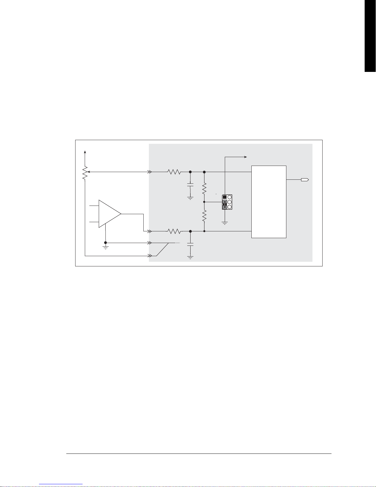
B.1.5 Analog Features
178 kW
ADC_IN0
AGND
+ V
ADC_IN1
VREF
178 kW
1 nF
20 kW
ADC
20 kW
1 nF
User Circuits
JP7
The RCM3700 Prototyping Board has an onboard ADS7870 A/D converter to demonstrate the interface capabilities of the Rabbit 3000. The A/D converter multiplexes converted signals from eight single-ended or three differential inputs to alternate Serial Port B
on the Rabbit 3000 (Parallel Port pins PD4 and PD5).
B.1.5.1 A/D Converter Inputs
Figure B-5 shows a pair of A/D converter input circuits. The resistors form an approximately 10:1 attenuator, and the capacitor filters noise pulses from the A/D converter input.
RCM3700
Figure B-5. A/D Converter Inputs
The A/D converter chip can make either single-ended or differential measurements
depending on the value of the
opmode parameter in the software function call. Adjacent
A/D converter inputs can be paired to make differential measurements. The default setup
on the Prototyping Board is to measure only positive voltages for the ranges listed in
Table B-2.
RabbitCore RCM3700 User’s Manual 98
 Loading...