

Page 1
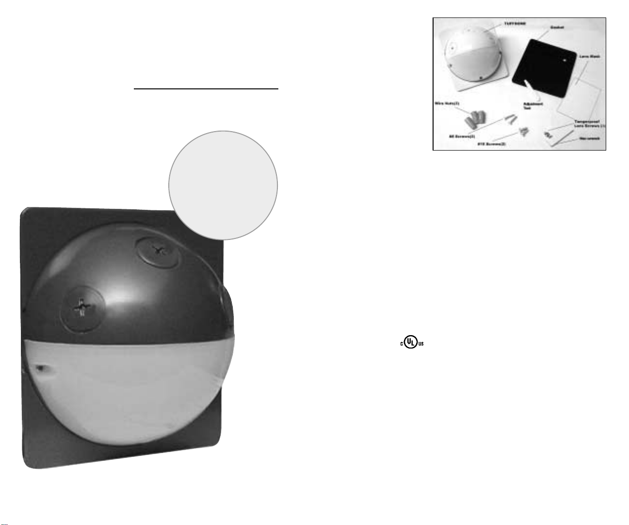
Tuf f Dome
Vandal Resistant
Outdoor Motion Sensor
Installation Manual
Contents
Specifications
It’s easy
to add
vandal resistant
motion detection
to outdoor
lights!
RAB
Switching Capacity:
Relay On/Off Model:
500 watts Incandescent when used
remotely, 250 watts when floodlights
are mounted to it.
250 watts Fluorescent @ 120 volts
Hi/Lo Model:
Runs at 20% lamp wattage from
dusk to dawn. Brightens to full
wattage upon sensor detection.
180 watts Incandescent maximum.
Voltage:
120 Volts AC
Power Consumption:
One watt
UL Listing:
Raintight Photoelectric
Switch. Suitable for wet locations.
Time Adjustment:
5 seconds to 15 minutes
Quick Test Time:
5 second test time for fast installation.
Works day or night.
Detection Zone:
Full180º by 30’
“No Hands” Auto Testing:
Auto mode starts after 3 minutes of
testing. No adjustment needed.
Built for Severe Conditions:
Double weatherproofing for long life.
Photoelectric Control:
Deactivates lights during daylight.
Fully adjustable for 24 hour
operation or custom applications.
Vandal Resistant Lens:
Hard lens resists casual vandalism.
Case Construction:
Precision molded Lexan®
Color Matched Lens:
Dark lens with black units.
White lens with white units.
Surge Protection:
Withstands up to 3000 volts
Manual Override:
Double flip wall switch logic prevents
activation by short power outages.
Resets to auto at dawn. No extra
wiring needed.
LED Detection Indicator:
Glows red day and night for
“on-guard” deterrence.
RF Immunity:
Circuits fully shielded for maximum
radio frequency immunity.
2
Page 2
Why RAB Sensors are Best for You
Cautions
Assembly and Wiring
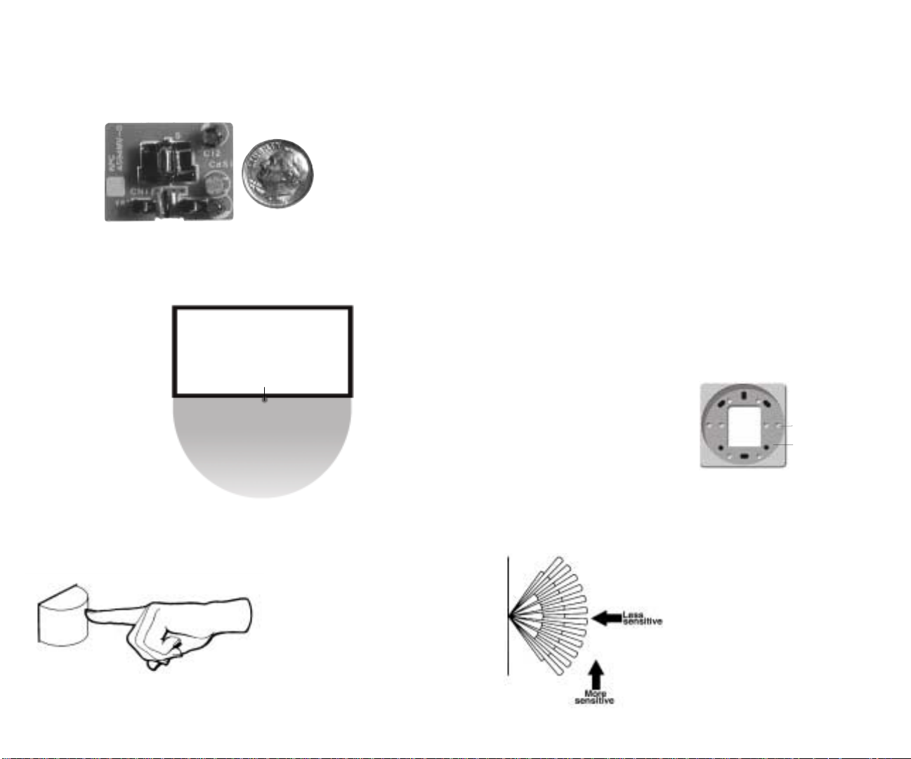
Smaller is better! Tuff Dome uses state-of-the-art surface mount
technology (SMT), just like cellular phones and beepers.SMT gives you
more reliability, greater RF immunity, and a compact sensor that can fit
neatly where others cannot.
Wider is better! The wide 180º view detects movement along the
entire side of a building with only one compact sensor.It will detect
people as they exit or enter. It takes several conventional sensors to
get the same coverage.
Sensor
180º
Molded is better! No leaky gaskets or bug hotels with Tuff Dome.
The hard lens is molded as part of the case. It’s vandalproof, rainproof,
bugproof and absolutely sealed.
• All wiring MUST comply with local
electrical codes and should be
installed by a qualified electrician.
• Read entire Installation Manual
before proceeding.
TURN OFF POWER BY REMOVING
POWER FUSE OR TURNING
OFF CIRCUIT BREAKER
BEFORE INSTALLATION.
• Total lighting load must not exceed:
Relay On/Off Model: 5 amps,
500 watts incandescent quartz
when sensor is used remotely
(250 watts when floodlights are
mounted to sensor) or 250 watt
fluorescent at 120 volts.To switch
more wattage, an electrician can
install an additional relay.
Hi/Lo Model: 180 watts quartz
and incandescent only.
• Line Carrier Remote Control
Systems such as X-10, Leviton or
Radio Shack are incompatible with
sensors and cause false activations.
• Do not install on circuits feeding
motor loads such as kitchen appliances, HVAC equipment, washer/
dryer or garage door openers.
• Sensor functions best when
movement is across its detection
pattern, not towards the sensor.
TURN OFF POWER BY REMOVING
POWER FUSE OR TURNING OFF
CIRCUIT BREAKER BEFORE
INSTALLATION.
1.Tuff Dome sensors should be wall
mounted.
2. Remove plastic lens cover and Tuff
Dome sensor assembly to separate
sensor assembly from mounting plate.
3.Tuff Dome can be mounted to 4”
round outlet boxes, octagon, single rectangular or Gem boxes.
4. Place the rectangular gasket supplied between the Tuff Dome mounting
plate and the chosen outlet box.
5. Put mounting plate on chosen
outlet box and match up holes.Tap
out knockouts if necessary.
Mounting plate
knockouts
(not drilled)
Indentation
for seating
Tuff Dome
6. If using floodlights, screw the
threaded arm(s) of each floodlight into
the die cast housing of the Tuff Dome.
Leave the locknuts and arm screws
loose until ready to aim. Always mount
the sensor below lights.Note:Floodlights
must not exceed a total of 240 watts.
7. Bring power leads, sensor leads
and floodlight leads into outlet box.
8. Make sure outlet box is properly
grounded.
9. Strip 1/2” of insulation from all leads.
Connect as shown in wiring diagram.
3
• Mount 6’-10’ high for optimum
range and direction.
4
Page 3
Vandalproof Installation
Wiring Diagrams
10.Twist on wire nuts, secure with
electrical tape.
11. Put round gasket between sensor
assembly and mounting plate.Use
keyhole slots to secure sensor assembly
to mounting plate.Use silicone sealant
around all openings if necessary.
12. Aim sensor.Perform Walk Test, see
section, “Aiming and Walk Testing”
on page 9.
13. Put lens cover back on Tuff Dome
using (3) screws.
14.Turn on power.
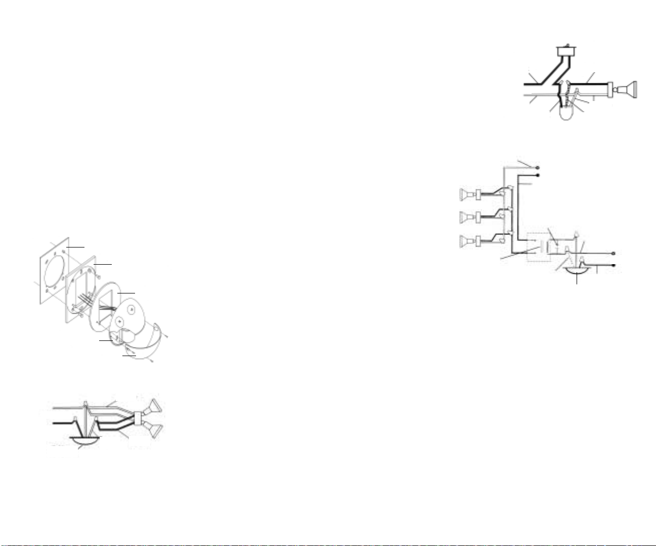
Tuff Dome Assembly
Gasket
Mounting Plate
Gasket
Sensor assembly
Lens cover
Basic Wiring Diagram
White
Power In
Black
Tuff Dome
Red
Screws:
Tuff Dome sensors are shipped with
stainless steel screws holding the
plastic lens on the front of the sensor.
If desired, you may install vandalproof
screws and tighten with Hex wrench
(screws and wrench supplied).
Plugs:
Tough Dome has three 1/2” plugs in
the die cast housing of the sensor.A
unique feature of these plugs is that
you may insure a vandalproof case
by removing the plugs, turning them
around, and re-installing the plugs from
the back of the Tuff Dome sensor (if you
are not using the holes for
lighting fixtures).
The reversed plugs do not have
screwdriver slots which reduce the
chance of tampering.
To override
sensor with a
manual switch
To switch more than rated load
(Relay model only)
Hi/Lo sensors can not accept an
auxiliary relay to increase their
switching capacity.
Relay rated to
handle load
required
Multiple Sensors:
Power Quality:
Black
Power In
White
White
Black
Black
.1µF
400V DC
Capacitor
White
Power In
Black
White
Red
Red
White
Power In
Black
Tuff Dome
Wiring more than one sensor
together is recommended only for
the experienced installer because
it becomes difficult to trobleshoot.
Single sensors that control their
own lights pinpoint movement
more accurately and operate
better.
Sensors should not be installed on
a circuit that also feeds motor
loads such as HVAC equipment,
kitchen appliances, or garage door
openers. If voltage varies significantly from 120 volts, sensors
may malfunction.
5
6
Page 4
How Does RAB’s Tuff Dome Work?
Picking A Location
The Tuff Dome infrared sensor
“sees” small temperature changes
caused by the motion of people or
cars within its Detection Zone and
turns on lights automatically.It welcomes visitors and may deter intruders.
How long do the lights stay on?
Lights remain on as long as there is
movement within the Detection Zone.
In Hi/Lo Model, lights revert to dim.
Once the zone is vacated, lights can
be adjusted to remain on approximately 5 seconds up to 15 minutes.
The Hi/Lo Model will keep lights on at
20% wattage from dusk until dawn
and then brightens to full wattage
when movement is detected.
Will the sensor detect animals?
Tuff Dome may detect large animals.
Having animals trigger the sensor
can give property a “lived-in”look.
You can limit animal detection by
placing opaque weatherproof tape
on the lower part of the lens or using
the bottom mask on the Lens Mask
Kit provided.
What does Manual Override do?
Keep lights on by flipping the wall
switch two times within 5 seconds.
Sensor resets to auto mode at
dawn. No extra wiring needed.
How are the Time Sensitivity and
Photocell adjusted?
• Time Control:
Sets the time that
lights will remain on after the Detection
Zone is vacated from approximately
5 seconds to 15 minutes.Use the
adjustment tool provided to turn
clockwise to increase the time.
• Factory Setting:5-8 minutes.
• Photocell Control:
For night only
operation, use the tool provided or a
small screwdriver to turn the Photocell
Control all the way counter-clockwise
(to the moon symbol).For operation in
low level lights, turn the knob all the
way clockwise (to the sun symbol).
Adjust counter-clockwise to have the
sensor come on later at dusk,
clockwise to have it come on earlier.
Hi/Lo Model:Turning photocell
control will show when the sensor
“thinks” the current ambient light
level = night, because the lights will
turn on low at 20% wattage.
Factory setting:Night Only
• Sensitivity:
Increases or decreases
the responsiveness and range of the
sensor.
Control Panel:
Turn controls gently.Do not force
past stops.
Sensitivity
Time Control
Location Considerations:
• Choose a location from which the
sensor can “see”all the paths of
movement that will be illuminated by
its lights.
•Tuff Dome is for wall mounting only.
• Sensor functions best when the
direction of expected movement
is across its detection pattern, not
towards the sensor.
• Locate 6-10’high on wall for
optimum range and detection.Lower
mounting height will reduce range.
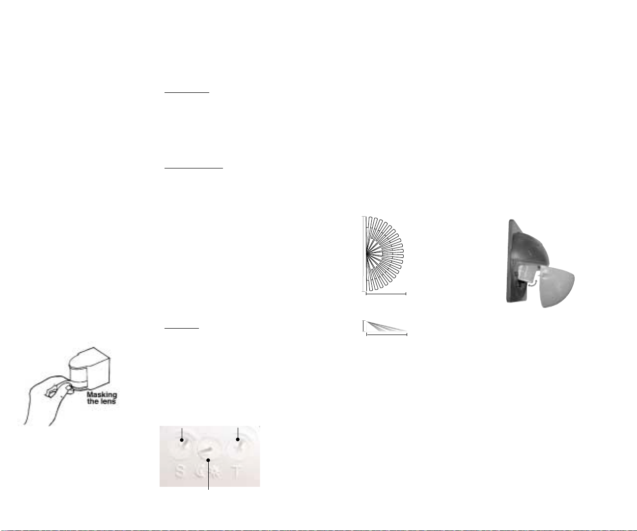
60’
Top View 30’
8’
Side View 30’
Double Look Down Lens
Detection Pattern
• The sensor has a “Double Look
Down” Lens with one “Look Out”
zone and two “Look Down”zones,
for excellent detection both at long
and close range.
• Detection extends out a maximum
of 30 feet and is 180º wide.
• To reduce the Detection Pattern
length, aim the sensor down.
• To Adjust Aiming:
1. Remove lens cover
2.Tilt sensor to desired angle
3. Re-install cover
• To reduce Detection Pattern width,
mask the sides of the lens with the
Lens Mask Kit provided or opaque
weatherproof tape.
• If sensor is mounted by a
doorway at the top of stairs, be
aware that the elevated mounting
height may extend the sensors
range.
• As distance from the sensor
increases, it will take more movement to be detected.For instance,
at 10 feet, a half step will be
enough, while at 30 feet, several
steps will be necessary.
Photocell
7
8
Page 5
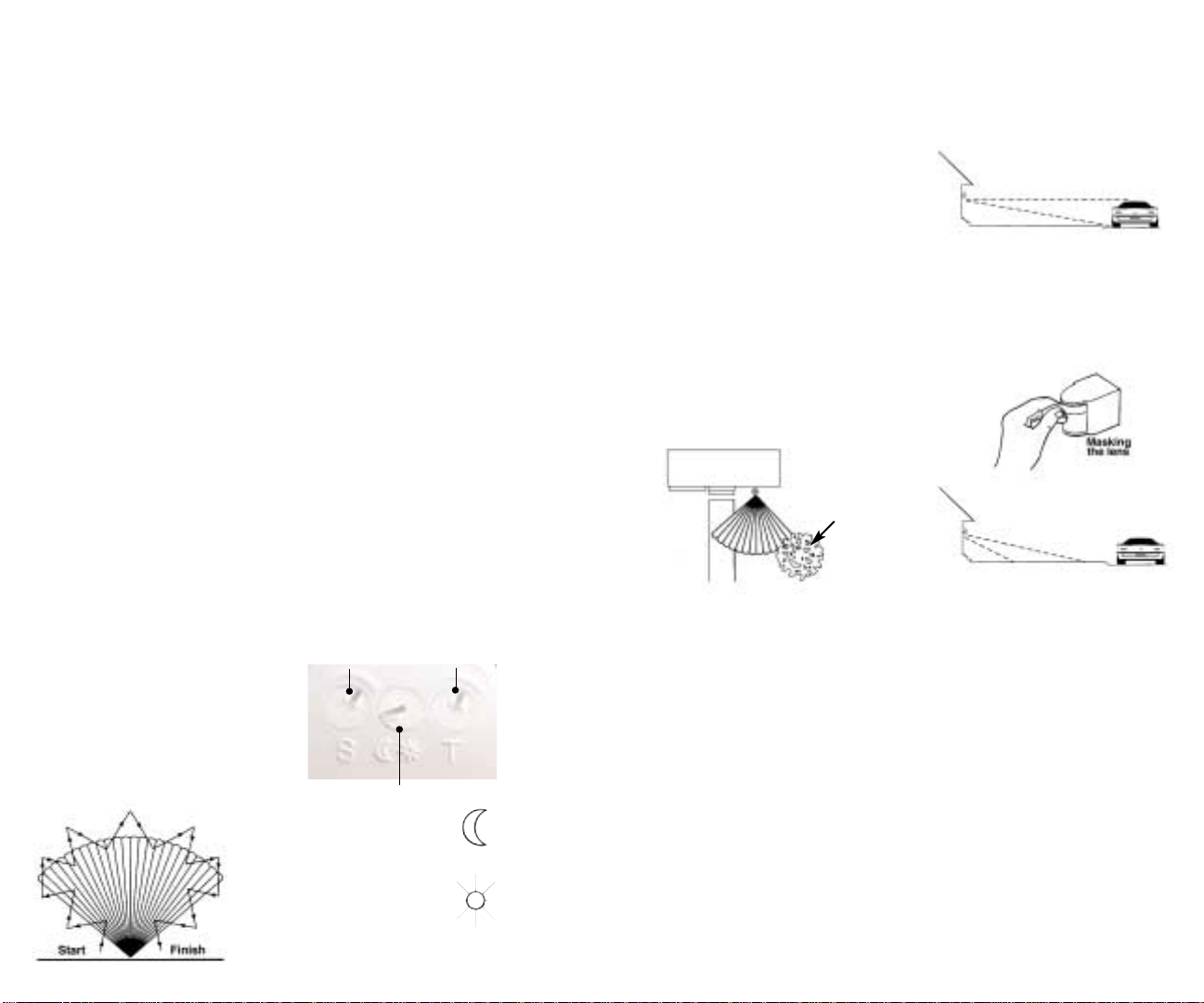
Aiming and Walk Testing
Test Period:
The sensor has a 3 minute Test
Period which allows it to be aimed
and walk tested day or night.
• For the first 30 seconds, the lights
will be turned on. During this time,
test that all fixtures and lamps
function properly.
• For the next 3 minutes, the sensor
will keep lights on for 5 seconds
each time it detects movement in its
Detection Zone.The sensor will
change to Automatic Mode after the
3 minute Test Period.
• If another 3 minute Test Period is
desired, turn the power off for at
least 10 seconds and back on again.
Walk Test:
The purpose of the Walk Test is to
check and adjust the coverage
pattern.
1. Aim the sensor approximately to
cover the area you desire.See aiming instructions on Pg. 8.
2. Start outside the Detection Zone
and walk across the zone until the
lights go on. As distance from the
sensor increases, it will take more
movement to be detected.For
instance, at 10 feet, a half step will
be enough. while at 30 feet, several
steps will be necessary.
3.To shorten the range, use the lens
masks provided or tilt the sensor
down to reduce coverage.
3. Repeat steps #2 and #3 until you
are satisfied with the range.
4.The Time Control is factory set
between 5-8 minutes.This period
starts after the movement in the
Detection Zone ceases.If less time
is desired, turn the time control
counterclockwise.For more time,
turn the control clockwise.
5.The sensor is factory set for night
only operation.To obtain operation
24 hours per day, turn the Photocell
Control full clockwise to the sun
symbol. Intermediate settings will
allow the sensor to operate earlier or
later at dusk.
6.Your sensor is ready for operation.
See the Technical Tips pages if
additional help is needed.
Control Panel:
Turn controls gently using the adjustment tool provided.Do not force past
stops.
Sensitivity
Time Control
Photocell
Turn to
moon symbol
for night only
Turn to
sun symbol
for 24 hour
operation
(lights turn on
night and day)
9
Technical Tips:
Lights Do Not Tur n Off
1. Make sure sensor is not aimed at
something that would move or
change temperature such as waving
branches, water, air conditioners,
windows or heating vents - even on
neighboring property.You can test for
infrared sources in the area by placing
a box or bag over the sensor. Put
sensor into Test Mode. After the initial
30 seconds of the lights being on,
lights should stay off.Wave your hand
inside the bag in front of sensor.
Lights should go on and then time
out. If sensor operates properly when
covered, check items 2-6.
Problem: Sensor is triggered by
unwanted movement or heat source.
Branches
blowing
may
activate
sensor
Solution:Tilt sensor (Pg.8) or mask
lens in the direction of the source.
Move sensor or source.
2.Make sure sensor is mounted firmly
and does not move even slightly
when touched. If it moves, tighten all
screws.
3. Make sure that Tuff Dome is not
mounted on an unstable object such
as a tree or a pole that will move in
the wind.
4.Was sensor wired hot? If so,
circuitry may have been damaged.
5. Make sure sensor is not aimed
within 30 feet of a road.
Problem:Passing cars activ ate sensor.
Solution: A 20’safety zone between
the sensor and road is recommended
to avoid activation from passing cars .
You may tilt sensor down (Pg. 8) or
mask top of sensor lens to reduce
range.
6. Make sure heat from lights is not
triggering sensor.Make sure the
sensor is below and as far as possible
away from lights.
7. Hi/Lo Models only:
Remember
that the lights will stay on in low
mode at 20% wattage from dusk to
dawn.This is normal operation.If the
Photocell Control is turned to the
sun symbol, the lights will stay on in
low mode in low level light and night.
If you desire low mode from dusk
until dawn only, turn the Photocell
Control fully counter clockwise to the
moon symbol.
Tips 1-6 above apply only if the
lights are staying on in high full
wattage mode.
10
Page 6
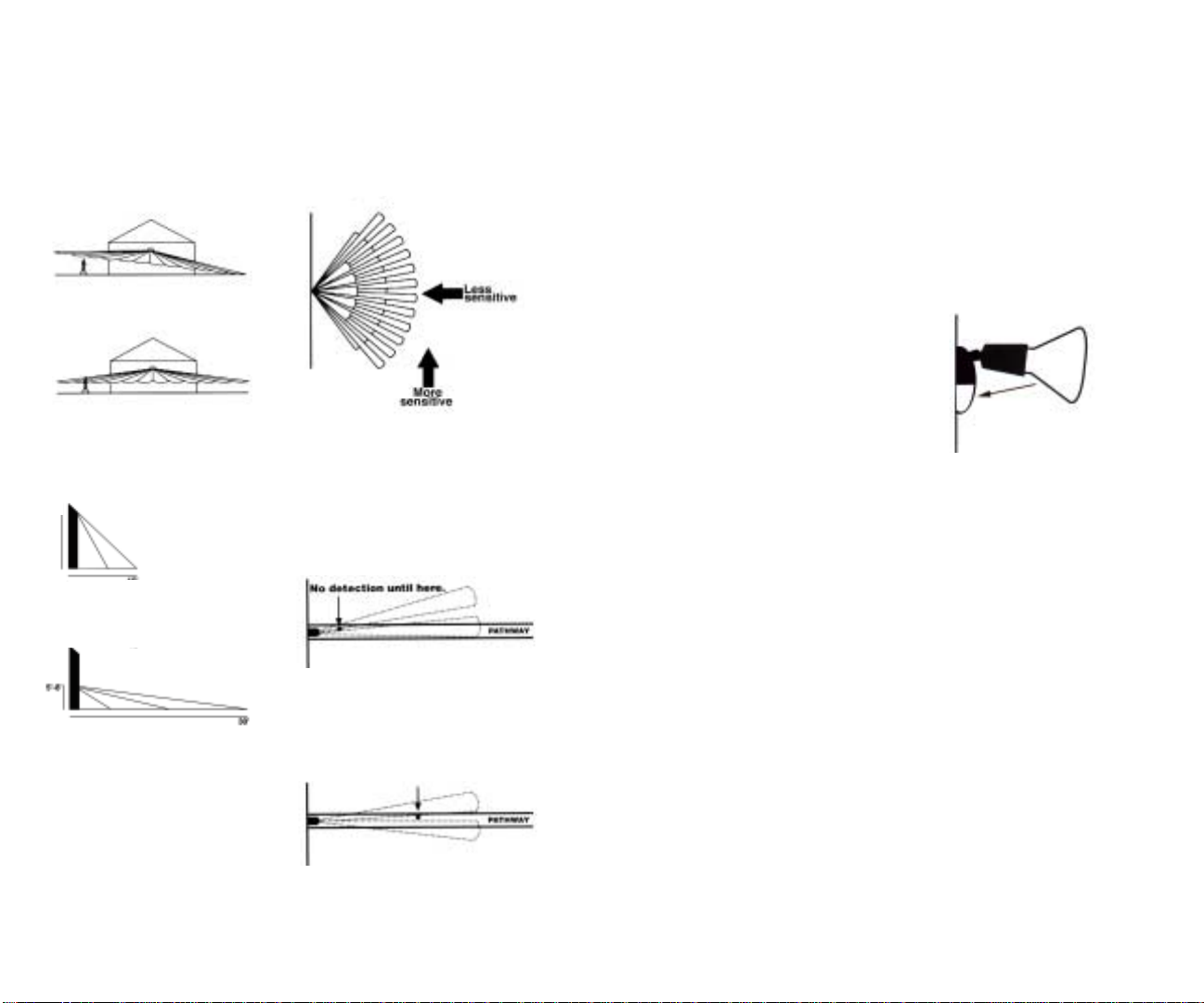
Technical Tips:
Range appears limited
Technical Tips:
Lights Do Not Tur n On
Lights Tur n Off
Too Quickly
1. Check that the sensor is level from
side to side and pointed at the area
you desire.If unit is tilted, part of the
Detection Zone may be high in the
air over peoples heads.
Solution: Position sensor exactly
level from side to side.
2. Check that the sensor is not
mounted too high. If mounted above
20 feet, much of the usable range
will be lost.
20’
20’
Solution: Mounting at 5’to 8’allows
maximum range.
4. Check that movement is not directly towards sensor.Sensor will see
movement across its pattern more
quickly. To fix, move the sensor.
5. Check that movement far away
and directly towards sensor is not
entirely within one Detection Pattern
finger.
Problem:Sensor will not detect until
movement crosses from one finger
into a second finger.
Solution:“Micro Adjust”sensor by
opening lens cover and tilting sensor
1/16”.This small adjustment may
move the zones to allow earlier
detection.
1. Check that lamps and fixtures
work. Compare wiring to the Wiring
Diagram in this manual.Check that
the power is on.
2. If installing during daylight, remember that the sensor will provide a 3
minute Test Period after power is
turned on. After 3 minutes, the sensor
will switch to Automatic Mode and will
not work during daylight if the
Photocell Control is turned to or near
the night only position (fully counter
clockwise to the moon symbol).
If you require another 3 minute Test
Period, turn the power off for at least
10 seconds and back on again.
If you require the sensor to operate
both in low level light and at night,
turn the Photocell Control knob fully
clockwise to the sun symbol.
3. Check that lights from other
sources, such as adjacent porch
lights, garden lights, streetlights or
lights from inside the house are not in
the sensor’s view. See #1 under
“Lights T urn Off T oo Quickly”.
4.Was sensor wired hot? If so,
circuitry may have been damaged.
5. If sensor is painted, make sure
there is no paint on the lens.
1. Check if sensor is being “tricked”
by reflected light.If lights shine or
reflect into the photocell, (located
behind the lens), the unit will go on
briefly and turn off thinking it is
daytime.
Problems:
Lights reflect into photocell or
lights shine directly into photocell.
Solution: Adjust Photocell Control
slightly clockwise, toward the sun
symbol.This allows the sensor to
function in brighter ambient light
conditions. Alternatively, move the
lights to avoid reflection.
2. Check if “R” lamps, “A” lamps or
self-ballasted PL lamps are being
used in a non-enclosed lampholder
that can be “seen”by the sensor. If
so, switch to reflector PAR floodlight
lamps or Quartz floods so the sensor is not affected by stray light. If
using PAR floodlights, consider using
lower wattage, energy saving lamps.
Self ballasted compact fluorescent
lamps may cause the sensor to
cycle on and off.
11
12
Page 7
Technical Tips:
Lights Tur n On and Off Incorrectly
Technical Tips:
Lights Tur n On For Unknown Reasons
1. Make sure the sensor is installed
on its own dedicated circuit free of
motor loads such as HVAC
equipment, kitchen appliances or
garage door openers.
2. It is not recommended to wire
sensors in parallel.More than one
sensor wired together makes them
difficult to troubleshoot.Disconnect
multiple sensors and test separately.
3. Keep all people completely out of
the detection pattern to make sure
the sensor is not detecting them.
4. Make sure sensor is located
below and as far as possible from
its lights.Heat from the lights may
trigger the sensor.
Solution: Make sure lights are
mounted above, not below, sensor.
5. Make sure lights are not visible
from or reflecting back into sensor.
Check for white or reflective surfaces
close to the sensor.
6. Heavy rain, snow or high winds
may activate the sensor occassionally.
Solution: Reduce sensitivity control
settings, mount in a more protected
area and/or mask the lens if this is a
constant problem.
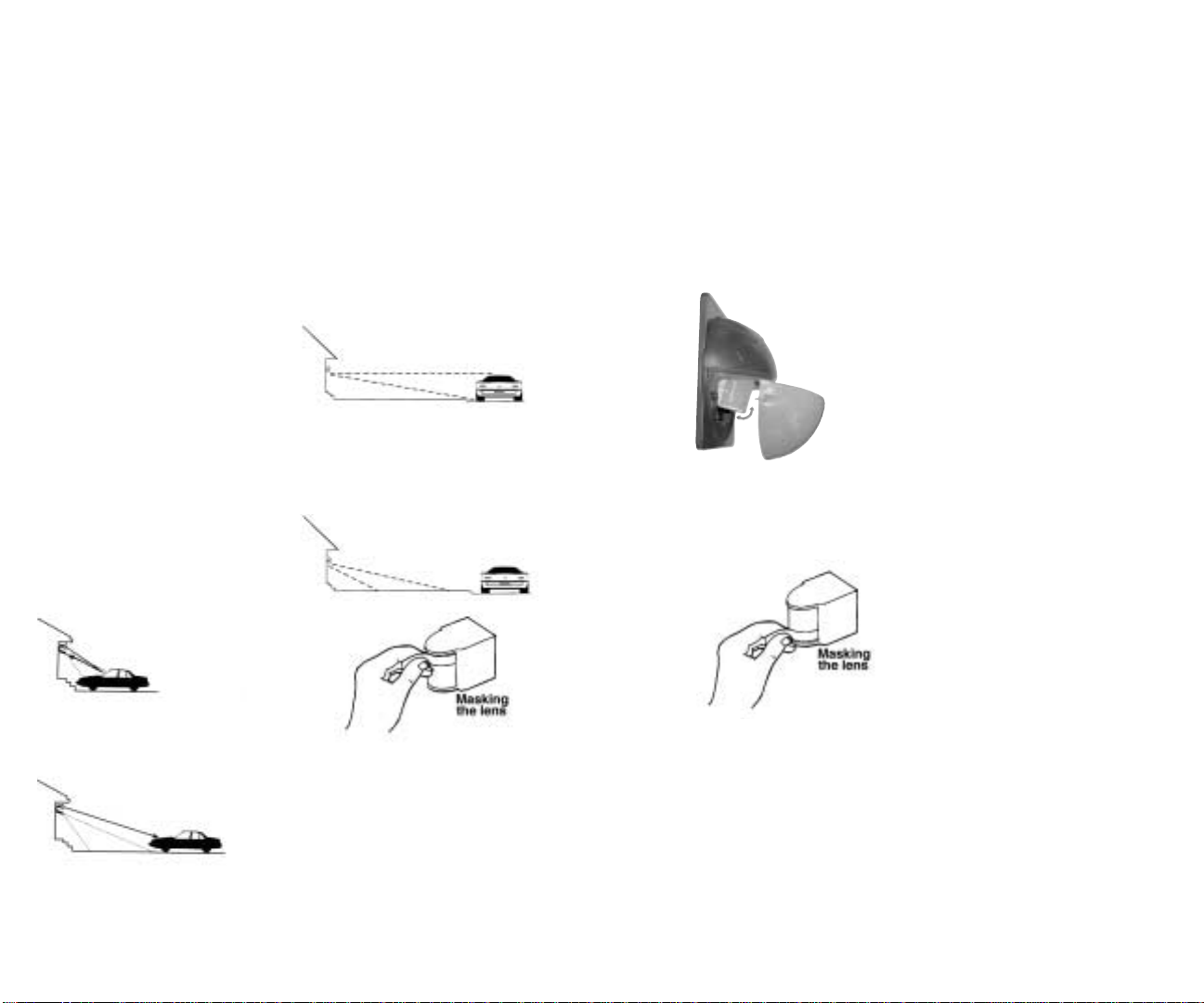
7. Make sure sensor is not aimed
within 30’of a road or sidewalk.
Passing cars will activate sensor.
Solution: Remove Tuff Dome lens to
expose sensor, tilt down (see pg. 8)
or mask the top of the sensor lens to
reduce Detection Pattern Length.
1. Lights may turn on occassionally
during rain, snow and windstorms
because the sensor is detecting
changes in temperature.If this is a
constant problem, mount the sensor
in a more protected area.
2.Tilt the sensor lower - it may be
seeing distant objects moving.
Remove 2 screws
and lens to
access sensor.
3.You may not be aware that animals
have triggered sensor.Check sensor
aiming to reduce nuisance triggering
or mask the lower part of the lens
with opaque weatherproof tape.
Solution: Aim lights away from
sensor and reflective objects or
mask the lens in the direction of
the light or reflection.
8. Self ballasted PL lamps may
cause cycling (on-off).
9. Check solutions 1,2,3,5 & 6 under
“Lights Do Not Turn Off” (Page 10).
13
4.The sensor may turn on
occassionally during voltage surges.
5. A possible source of “mysterious”
sensor activations are strong local
radio signals.Check for nearby CB,
Ham, VHF radio transmitters or
Cellular telephones.The sensor may
be activated, but will not be permanently impaired by these signals.
5. Check other solutions mentioned
on pages 12 &13.
14
Page 8

Limited Warranty
Toll Free
Technical Assistance
Your Tuff Dome will be promptly
replaced or repaired, at our option, if
it proves to be defective in workmanship or materials within 5 years of
purchase.
For repair or replacement, please call
the Tech Help Line at 888 RAB-1000
for instructions.
If the sensor is out of warranty or
damage is unrelated to its original
manufacture, return your unit freight
prepaid to the address below.Please
include a description of the problem
and a check for $20.00 (made out to
RAB Electric). We will repair or
replace your unit promptly.
Under no circumstances shall RAB
Electric be liable for any incidental or
consequential damages arising out
of or in connection with the use or
performance of this product or other
indirect damages with respect to loss
of property or revenue or cost of
installation, removal or re-installation.
This warranty gives you specific legal
rights and you may also have other
rights which vary from state to state.
Tuff Dome is designed to detect
people or cars in the detection area.
It should not be construed as a theft
or crime prevention device. RAB
does not accept responsibility for any
damages resulting from intrusion or
other crimes.
If you need technical assistance,
please do the following:
1.Re-read the T echnical Tips sections
of this manual.
2.Call the Tech Help Line
at 888 RAB-1000, 8AM to 4PM
Eastern Time M-F and we will be glad
to help you.Before y ou call, please
have the follo wing information handy:
a) Catalog number of your unit;
b) Wattage , types and locations of
lights connected to the sensor;
c) The electrical circuit on which the
sensor is installed.What else does it
feed? How is the sensor power
switched?
d) Serial Number (4 digits) on the
back of the sensor.
e) This installation Manual
Note: RAB Electric cannot give
electrical wiring instructions by
phone. Please consult a qualified
electrician.
15
RAB ELECTRIC MANUFACTURING, INC.
170 Ludlow Aven ue , Northvale, NJ 07647 USA
Over 25 warehouses nationwide.
Tech Help Line Fax Back Website e-mail
888 RAB-1000 888 RAB-1236 www.rabweb.com [email protected]
©RAB Electric, 9/01
 Loading...