

—
R9 Technology
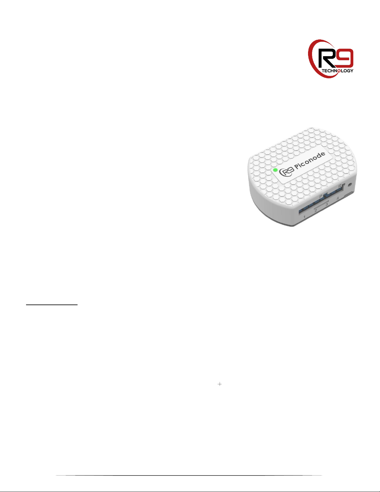
SN400 Sensor Node
Installation Guide
This instruction sheet provides information
regarding indoor installation of R9
Technology’s SN400 Sensor Node.
Required Items:
Items included in the SN400 Smart Sensor Node kit:
• Qty 01, SN400 Sensor Node
• Qty 01 to 04, 6’ Temperature probes
Additional items needed but not included in the kit:
• Qty 02, AAA alkaline batteries
Additional items required depending on the mounting option selected for each node.
• Qty 01, Phillips sheet metal screws M4-0.7 X 10mm and Philips head screwdriver
• Option- Velcro/double sided tape kit (replacement for sheet metal screw or magnetic sensor node attachment)
• Foil or clear tape
• Tie wrap mounting base in desired color (for cable routing and probe mount)
• Mild cleaning agent or rubbing alcohol
• Clean rag or towel
1
Mounting Location Considerations:
1. Preferred mounting location shall be adhered directly to the
equipment to be monitored at the highest available location. It is
common for equipment to be periodically moved for cleaning so
minimize cable routing between multiple equipment pieces. Ideally
the nodes antenna will extend beyond the top of the unit being
monitored.
2. The SN400 node must be installed in a secure location and as high
as possible for best reception.
3. The SN400 node must be located within 5 feet of the final
temperature sensor location. If this is not possible longer
temperature sensors can be procured.
4. Select a location that is not susceptible to drastic temperature
changes. An indoor, controlled temperature environment is
preferred. The standard SN400 enclosure is not rated for outdoor
use. Ensure the unit is not exposed to extreme heat or cold so
that the enclosure will not be damaged by external factors (for
example, heat from ovens, cooling racks, exhaust).
5. To ensure the best signal reception select an installation location
that is free of obstacles that reflect and absorb radio frequency
signals (RF), as well as interference that may distort signals.
Avoid installation near or in the path of strong RF fields. (i.e.,
computers, microwaves, wireless phones, etc.) and on or near
metal objects, air conditioners and heater ducts since they may
cause interference and reduce the node’s sensitivity.
6. Avoid installing a SN400 in below ground areas such as a
basement as the range of the unit is reduced when installed below
ground level. However, if it is absolutely necessary place the node
as high as possible. If required an antenna extender can be
procured from R9 Technology to increase signal reception.
7. Install the node in an “out of the way” location that does not affect
8. Install the node in a location that is free from dripping water, heavy
.
the daily lives and working conditions of the employees. Ensure
each temperature sensor connected to the node will not be
affected by routine maintenance or cleaning of the equipment. (for
example, freezers being moved for cleaning). Locate the node in
a place that allows easy access for servicing and changing
batteries.
dew and humidity. Also take precautions to prevent water from
flowing into the node along the cables.
2

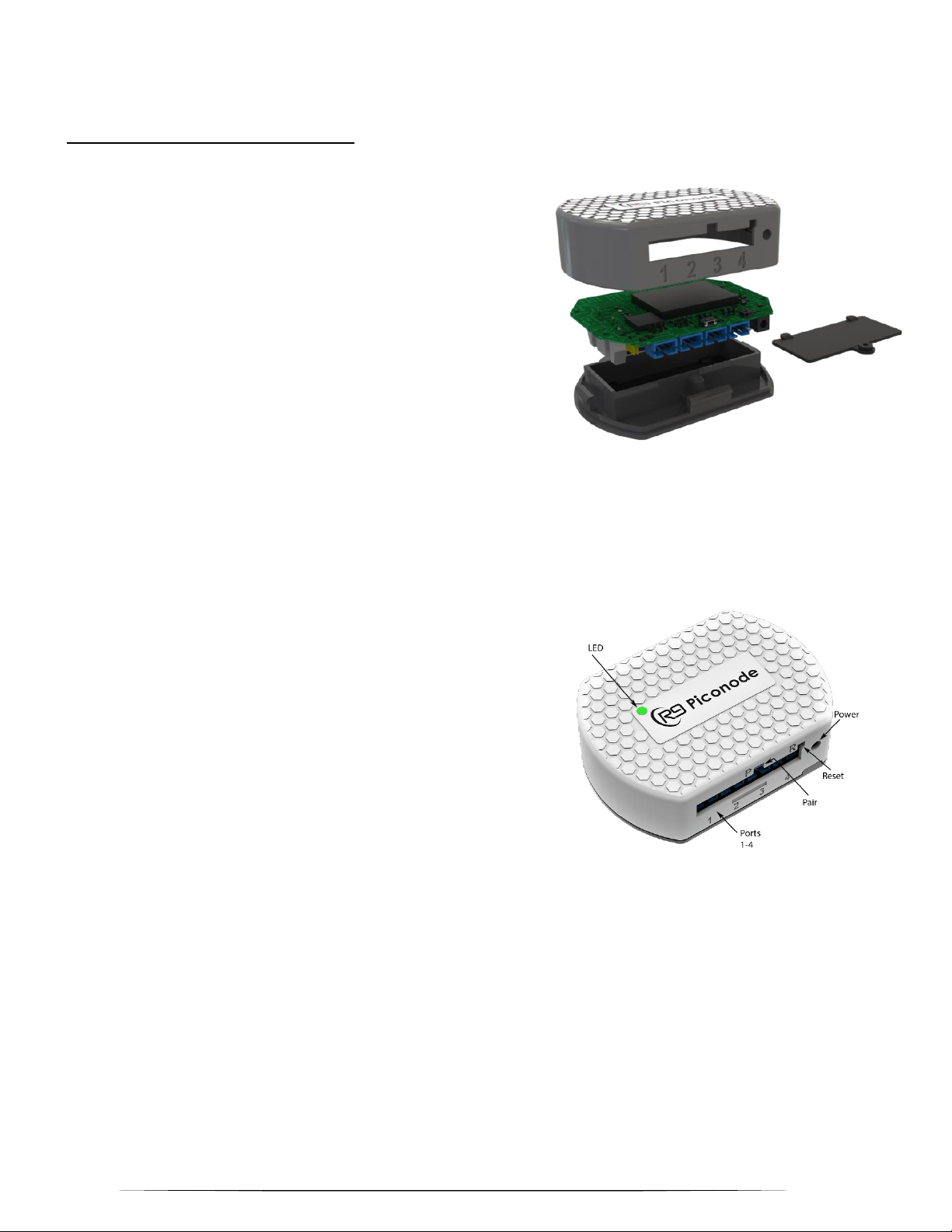
Installation Instructions:
Once an indoor mounting location has been identified follow the installation steps listed below (note that the standard SN400 enclosure is for
indoor use only, an optional outdoor enclosure can be obtained).
Step 1
Remove the battery compartment lid located on the rear of the SN400 and install 2 AAA batteries in the correct orientation (marked on
battery holder) and replace lid. Refer to Figure 1.
Figure 1
Step 2
Use rubbing alcohol or other mild cleaning agent to remove debris and oils from any mounting surface where adhesive tape
will be adhered. Rubbing alcohol can also easily remove frost from internal freezer surfaces.
Step 3
Mount the SN400 in desired location (refer to Figure 3). There are three primary methods for mounting. Ensure mounting
flange is pointing upward.
• The SN400 enclosure has integrated magnets for mounting to ferrous metal surfaces. The magnets are located at
the lower edge of the SN400 which makes it possible to elevate the SN400 antenna above the metal surface into
free space (if required for better RF reception).
• Or, a single sheet metal screw can be attached through the SN400 mounting flange (top of SN400 enclosure).
3

• Or, use Velcro/double sided tape to secure the SN400 to smooth, clean surfaces.
Figure 3
Step 4
Identify the specific location(s) for the temperature probes based on the areas to be monitored. Ensure the length of the
probe wire is sufficient to terminate to the SN400. When mounting to a metal surface (freezer) do not allow metal probe
housing to contact the metal freezer surface. Use a tape adhered tie wrap mounting base as shown in figure 4. These
mounting bases can also be used for routing wires.
4

Step 5
Use alcohol or other mild cleaning agent to remove debris, oils and frost (inside freezer) from the mounting surface.
Step 6
Place the temperature sensor(s) in the location(s) and adhere in place using foil/clear tape and/or tie wrap mounting bases to ensure a neat
and clean install. Refer to Figure 5
Figure 4
Figure 5
Step 7
Route the temperature probe cable out of the unit being monitored and secure in place. If exiting equipment
(refrigerator/freezer) which contains an insulation gasket, route the cable between the door and gasket. Ensure the cable
position is such that the flat cable surface is parallel to the gasket so to minimize gasket deformation. Close the door and use
the foil/clear tape to adhere the cable in place. Do not place tape or other materials in contact with the insulation gasket.
Step 8
Plug the connector end of the temperature sensor into Port 1 of the SN400 or the next available port. Ensure SN400 port
population is sequential starting from port 1 and incrementing up to port 4.
5

Step 9
Complete remaining temperature probe and cable installations. Ensure a neat and clean install.
Step 10
Installation is now complete. Verify sensor is recognized via the customer dashboard.
Step 11
From the customer dashboard verify the temperature changes values by applying a heating and cooling source to the temperature probe.
FCC Statement
Compliance Statement (Part 15.19)
This device complies with Part 15 of the FCC Rules. Operation is subject to the following two conditions:
1. This device may not cause harmful interference, and
2. This device must accept any interference received, including interference that may cause undesired operation.
Warning (Part 15.21)
Changes or modifications not expressly approved by the party responsible for compliance could void the user’s authority to operate the
equipment.
FCC Interference Statement (Part 15.105 (b))
NOTE:
This equipment has been tested and found to comply with the limits for a Class B digital device, pursuant to part 15 of the FCC Rules. These
limits are designed to provide reasonable protection against harmful interference in a residential installation. This equipment generates, uses
and can radiate radio frequency energy and, if not installed and used in accordance with the instructions, may cause harmful interference to
radio communications. However, there is no guarantee that interference will not occur in a particular installation. If this equipment does
cause harmful interference to radio or television reception, which can be determined by turning the equipment off and on, the user is
encouraged to try to correct the interference by one or more of the following measures:
—Reorient or relocate the receiving antenna.
—Increase the separation between the equipment and receiver.
—Connect the equipment into an outlet on a circuit different
from that to which the receiver is connected.
—Consult the dealer or an experienced radio/TV technician for help.
FCC Radiation Exposure Statement:
This equipment complies with the FCC radiation exposure limits set forth for an uncontrolled environment. This equipment should be
installed and operated with a minimum distance of 20cm between the radiator and all persons. This transmitter must not be co-located or
operating in conjunction with any other antenna or transmitter.
—
For questions and support, please contact
R9 Technology
17217 Waterview Parkway Suite 1.202Y
Dallas, TX, 75252, USA
Product information
www.r9tech.com
Support e-mail address
request@r9tech.com
6
 Loading...