

Page 1

RS-232
-
RS-485
INTERFACE CONVERTER
IC-485S
&
IC-485SI
User’s Manual
@Copyright 1994 ATEN@ International CO., LTD.
Manual part NO.PAPE-0075-200
Printed in Taiwan
06/94
Page 2

PACKAGE CHECKLIST
When you purchase this product, it should contain the
following elements:
l
IC-485S
l Power Adapter
l IC-485S
or IC-485SI Converter
&
IC-485SI User’s Manual x 1
(DC9V, 200mA)
x 1
x 1
Attention: To prevent electric shock caused by
lightening, you must provide a ground
path by connecting a wire from the
Grounding Tab to the earth ground
(for IC-485SI
only).
Page 3
FUNCTION OVERVIEW
IC-485S/IC-485SI
TABLE OF CONTENTS
1 FUNCTION OVERVIEW
l-l Introduction
l-2 Specifications.
2 INSTALLATION
2-
1 Installation Procedure.
.......................
.....................
....................
2-2 Switch Function Description
3 OPERATION
.......................
3-l Point-to-Paint/4-Wire Full Duplex
3-2 Point-to-Paint/2-Wire Half Duplex
3-3 Multidrop/4-Wire Full Duplex.
3-4 Multidrop/2-Wire Half Duplex
3-5
Simplex/Transmit,
3-6 Monitoring
4 OTHERS
4-
1 Terminal Block Definition.
4-2 Self Test
(for IC-485s only)
..........................
.........................
APPENDIX A
Trouble Shooting
RS-232
DCE/DTE
.....................
Description
Preventing Radio & TV Interference.
.............
...............
..........
Receive Only.
..........
..........
.....
.....
.......
.......
.....
......
.....
9
10
11
12
13
14
14
15
16
17
18
1 FUNCTION OVERVIEW
l-l INTRODUCTION
1
1
2
3
3
4
6
8
The IC-485S and IC-485SI are a series of a
rectional interface converters for RS-232 and
bi-di-
RS-
485. The IC-485SI has built-in isolators for high
voltage
(2OOOV)
ic-485s & IC-485SI,
protection. With the IC-485 series,
it provides Point-to-Point,
Multidrop and Simplex operations. The IC-485s
provides an extra Monitoring function.
The IC-485 can be powered from the following two
ways:
1)
a DC
9V, 2OOmA
power adapter
2) the pin #9 of the RS-232 connecter
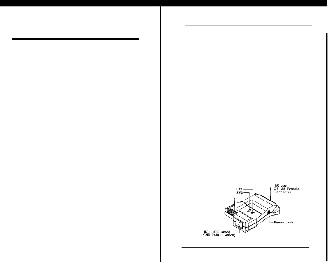
Two slide switches are used to configure its op-
eration mode, contention control, and assignment of
the RS-232. Following figure is the IC-485’s exter-
nal view.
DB-85 Female
Terminal Block
RJ-ll(ICG485S)
GND TAB(G485SI)
Figure l-l External View
User’s Manual
1
Page 4
IC-485S/IC-485SI
FUNCTION OVERVIEW
INSTALLATION
2 INSTALLATION
IC-485S/IC-485SI
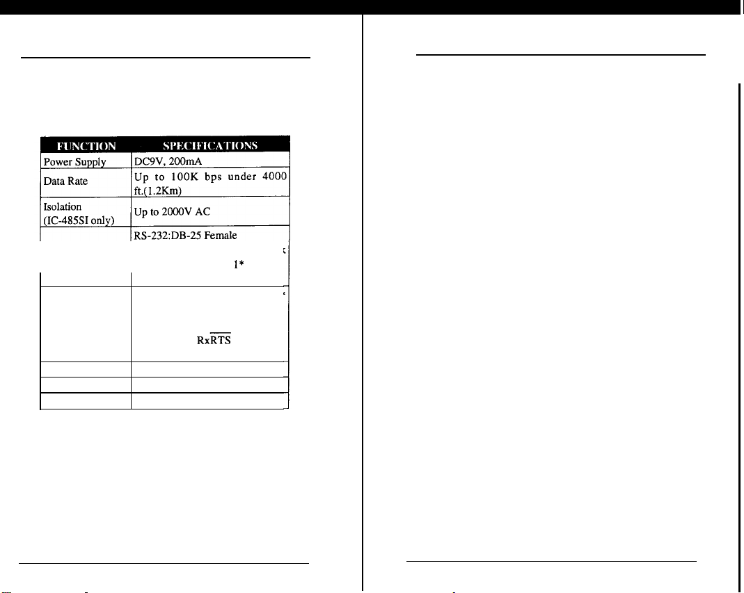
1-2 SPECIFICATIONS
Connector
Function Switch
Enclosure
Weight
Dimensions
RS-485/422:
SWl:DCE,DTE,
SW2:TxON. RxON
SW2:TxRTS,
SW2:TxRTS. RxON
Plastic
60 gm
54x74.5x18.5mm
A 4 terminal block
and RJ-1 l* or
TAB**
selection
RXXrt
Figure l-2 IC-485 Specifications Table
&
* RJ-11 Connector
Monitor mode for
IC-485S only.
* * Grounding TAB for IC-485SI only.
GND
MONITOR*
2-1 INSTALLATION PROCEDURE
Before installing the IC-485 you will need a
wire cable. This cable must go from your location to
the place you want to connect to.
Installation Procedure:
1
Before installing the IC-485 to the PC, decide
one of the 6 possible configurations suitable
for your application. Please check Chapter 3
OPERATION for correct slide switch settings
and phone wires connection, then connect
IC-
485 to the PC.
For IC-485SI: Connect a wire from the
Grounding Tab to the earth
ground.
2.
Turn on PCs.
3.
Insert the adapter’s plug into the POWER
JACK in the right side.
4.
Plug the power adapter into an AC outlet. The
unit is now ready for operation.
4-
2
User’s Manual
User’s Manual
3
Page 5

IC-485S/IC-485SI
INSTALLATION
INSTALLATION
IC-485S/IC-485SI
2-2 SWITCH FUNCTION DESCRIPTION
Refer to the location of the SW1 and SW2, please see
Figure
1-
1.
IC-485S:
IC-485SI:
SW 1: Device Mode Selection
Position 1: DCE means the IC-485 is set at DCE
mode and it must be connected to a DTE
device.
Position 2: DTE means the IC-485 is set at DTE
mode and it must be connected to a DCE
device.
Position 3: Monitor means the IC-485S is set at
monitor mode and it is used to monitor
the RS-485 line signals (for
IC-485S
only).
SW2: Transmitting and Receiving mode selection
Position 1:
(TxON, RxON)
means the IC-485 is
always in transmitting mode and in receiving mode.(using in Point-to-Point
mode)
Position 2:
(TxRTS, RxRTS)
means the K-485 is in
transmitting mode while RTS signal is at
high level and it is in receiving mode
while RTS signal is at low level.(using
in Multidrop mode)
Position 3:
(TxRTS, RxON)
means the IC-485 is
always in receiving mode and it is in
transmitting mode only while RTS signal is at high level.(using in Multidrop
mode to monitor the RS-485 line signals)
Note:
DTE means Data Terminal Equipment.
DCE means Data Communication
Equipment.
More detailed information, please refer
to the Appendix.
-____
4
User’s Manual
User’s Manual
5
Page 6

IC-485S/IC-485SI
OPERATION
OPERATION
IC-485S/IC-485SI
3 OPERATION
The IC-485S & IC-485SI supports 4 kinds of
functions in 6 kinds of configurations. They are
1. Point-to-Point
Point-to-Point configuration means two devices
which locate at two different places can be linked
together to communicate through a couple of IC-485
devices.
3-
1
1.1 Point-to-Paint/4-Wire Full Duplex( Fig.
)
1.2 Point-to-Pointi2-Wire Half Duplex( Fig. 3-2
2. Multidrop
Multidrop configuration means that more than
two devices can be linked all together to communicate one another through many IC-485 devices. In
this configuration, one of the IC-485 devices will be
connected to a master device and the rest of IC-485
devices will be connected to many other slaver de-
vices.
2.1
Multidrop/4-Wire
Full Duplex( Fig. 3-3
)
Simplex configuration means that more than two
devices can be linked all together to communicate
IC-485
through many
devices. Its configuration is
like the Multidrop’s, but the master device can talk
and the
only
4. Monitor
Monitor
can
be
slaver devices can listen only.
Mode(
Fig. 3-6
)
(for IC-485S only)
configuration means a IC-485s device
wir ed to
the lines of RS-485 or RS-422 devices
to monitor the line signals. In this configuration the
IC-485S
R’ :
will change the function of T+ and T- to
:cncl P‘
r espectively
)
Before operating,
lation
according
user must complete the instal-
to the procedure mentioned in
Sec-
tion 2- 1
Once
the installation
should operate as the
had been done, the device
setting function.
2.2 Multidrop/2-Wire Half Duplex( Fig. 3-4
3. Simplex/Transmit, Receive
6
Only(
User’s Manual
)
Fig. 3-5 )
Page 7

IC-485S/IC-485SI
OPERATION
OPERATION
IC-485S/IC-485SI
3-1 POINT-TO-POINT/~-WIRE FULL DU-
PLEX A
r/
I
T+I
I
B
IR+
Configuration:
A1
DCWJITE ) TxON,RxON
B 1
DCE/DTE ) TxON,RxON
3-
Figure
1 POINT-TO-POINT/4-WIRE FULL
DUPLEX
In above Figure if the PC 1 is a
DTE
device, then
the Device A should set the SW1 to DCE. If the PC1
is a DCE device, then the Device A should set the
DTE.
SW1 to
The switch setting method for the
Device B is identical to Device A’s.
3-2 POINT-TO-POINT/2-WIRE HALF DU-
/
Configuration:
Figure 3-2 POINT-TO-POINT/2-WIRE H-
ALF DUPLEX
Note: All the SW1 setting in this Chapter are follow-
ing the setting rule indicated in this Section.
8
User’s Manual
User’s Manual
9
Page 8

IC-485S/IC-485SI
OPERATION
---.-
__
OPERATION
IC-485S/IC-485SI
3-3 MULTIDROP/4-WIRE
PC1 =>
COM1/
COM2
FULL DUPLEX
Bl
=>PC2
COM1/
COM2
=>PC3
COM1/
COM2
=>PC4
COM1/
COM2
Configuration:
Bn
DCE/DTE ] TxRTS, RxON
Note: Bn means any one of the B 1, B2, B3 and SO
on.
MULTIDROP/2-WIRE
3-4
PC1
COM1/
COM2
A
HALF DUPLEX
B1
R+
R-
Ii-485
b2
-I
=>PC2
COM1/
COM2
Configuration:
B
TxRTS,
RX
Note: Bn means any one of the B 1, B2, B3 and so on.
Figure 3-3
10
MULTIDROP/4-WIRE
FULL
User’s
DUPLEX
Figure 3-4 MULTIDROP/2-WIRE HALF
PLEX
Manual User’s Manual
DU-
11
Page 9

IC-485S/IC-485SI
OPERATION
OPERATION
IC-485S/IC-485SI
3-5 SIMPLEX/ TRANSMIT, RECEIVE ONLY
B1
PC1
COM1/
COM2
=>
=>PC2
COM1/
COM2
=>PC3
COM1/
COM2
=>PC4
COM1/
COM2
Configuration:
1
DCE/DTE 1TxON, RxON
A
1
Bn
DCE/DTE
)
TxON, RxON
Note: Bn means any one of the B 1, B2, B3 and so on.
Figure 3-5
SIMPLEX/TRANSMIT, REC-EIVE
ONLY
3-6 MONITORING
Device 1
RS-422lRS-405
--l
(for IC-485S
=>PC
R+
IC-48%
only)
Device 2
COMl/
COM2
Note: R+ and R- signals are converted and linked to
the RS-232 port, DB-25 pm 3. R’ + and R’
-
(T+ and T-) signals are converted and linked
to the RS-232 port, DB-25 pm 2.
Configuration:
1
MONI 1 TxRTS,
A
RxON
Note: The RTS must be at the low level in monitoring
mode.
Figure 3-6 MONITORING
12
User’s Manual
User’s Manual
13
Page 10

IC-485S/IC-485SI
OTHERS
OTHERS
IC-485S/IC-485SI
4 OTHERS
4-1 TERMINAL BLOCK DEFINITION
The four screw terminal block has different defi-
nition in different operation modes.
In the
DCE/DTE
#2(-V) are configured to transmit data, the transmitter; the terminals #3(-V) and
to receive data, the receiver.
In the MONITOR mode
#l
terminals
and #2 are respectively the positive and
negative of receiver
the positive and negative of receiver
Figure 4-l Terminal Block
mode, the terminal #l (+V) and
#4(+V)
are configured
(for
IC-485S only), the
#I;
the terminal #3 and
##4
are
#2.
4-2 SELF TEST
To test the internal circuit of the interface converter, connect a dumb terminal to the unit and process as follows:
1. Set SW1 to DCE (if the dumb terminal is a
DTE
configuration).
2. Set SW2 to
3. Connect one wire from
and connect another wire from TX-(#2) to
TxON, RxON.
Tx+(#l)
to
Rx+(#4),
Rx-
(#3X
4. Set the terminal to full duplex and enter data,
then the data should be displayed on the screen.
5. If this occurs the internal circuit is opera-
tional.
14
User’s Manual
User’s Manual
15
Page 11

APPENDIX A
TROUBLE SHOOTING
RS-232 DCE/DTE DESCRIPTION
atthe DC
transmission
Power Adapter is available.
.
Check that the IC-485
plugged securely in PC.
.
Check that the 4-wire cable
is connected properly
If failure of printing is still exists upon aforesaid
solutions, please contact your dealer for help.
9V
Device’s Connector Pin # Cables
IC-485
is
at
Note: The DTE mode device must be connectedto
a DCE mode device because the polarity
of the
communication signals are different. The
shadow area is a connection example for a
DTE device to a DCE device.
16
User’s Manual
User’s Manual
17
Page 12

3. Move the computer away from the receiver.
PREVENTING RADIO & TV INTERFERENCE
Warning this equipment generates, uses and radiates radio frequency energy and if not installed and
used in accordance with the instruction manual may
cause interference to radio and television reception.
It has been tested and found to comply with the limits
for a Class A computing device in accordance with
the specifications in Subpart J of Part 15 of FCC
Rules, which are designed to provide reasonable
protection against such interference when operated in
a commerical environment. Operation of this equipment in a residential area is likely to cause interference, in which case the user at his own expense will
be required to take whatever measures may be required to correct the interference.
If this equipment does cause interference to radio
or television reception, which can be determined by
turning the equipment off and on, the user is encouraged to try to correct the interference by one or more
of the following measures:
1. Reorient the receiving antenna.
4. Plug the computer into a different outlet so that
computer and receiver and on different branch
circuits.
5. Ensure that the mounting screws, attachment
connector screws and ground wires are tightly
secured.
6. Ensure that good quality, shielded and
grounded cables are used for data communications.
If necessary, the user should consult the dealer or
an experienced radio/television technician for addi-
tional suggestions.
2. Relocate the computer with respect to the receiver.
18
User’s Manual
User’s Manual
19
 Loading...