

Page 1

REVERSIBLE
l-IN-4-OUT
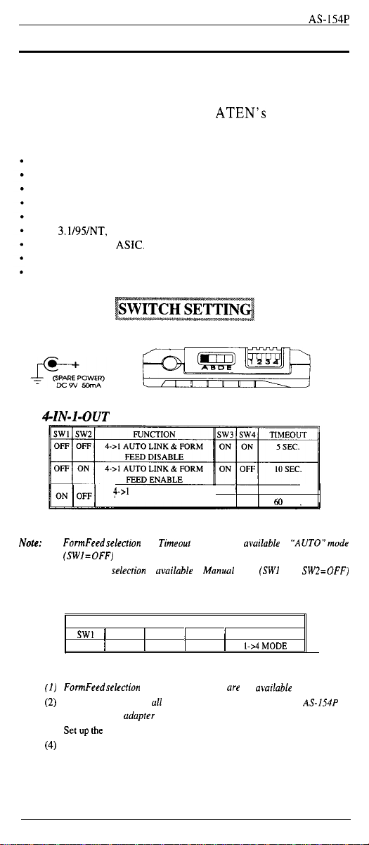
4-IN-l-OUT
PARALLEL
AUTO SWITCH
AS-154P
User’s Manual
Packing Checklist
l Reversible Auto Switch,
l User’s Manual,
l 3.5” Floppy xl
wm-m@,“hv-
0
Copyright 1997
Manual Part No
All brand names and trademarks we the
AS-154P
ATENO
Printed in Taiwan
AS-154P
mm-”
International Co., Ltd
PAPE-- 1042.600
02/97
regIstered
property of
their
Xl
Xl
respective owners
Page 2
Introduction
AS154P
Introduction
AS-154P reversible auto switch allows either 4-IN-l-OUT
or l-IN-4-OUT configuration. It helps to solve the problem
between multiple users and multiple peripherals with the
minimum cost. This unit has
technology which is both reliable and power free.
FEATURES:
Reversible.
Non-Powered.
Compact size.
Transparent to user.
Easy to install.
Win
3.1/95/NT,
Built-in powerful
FCC class B certificated.
Unique broadcast mode supported.
For
4-IN-I-OUT
DOS Resident software include.
ASK.
Mode
ATEN’s latest ASIC
MANUALMODE
4->I
ON1 25
OFF1OFF160SEC.
SEC.
OFF
1
Table A DIP switch
No&:
FormFeedselection
(I)
(SWI=OFF)
(2)
Slide switch selecrion is
only.
only
and
uvuilable
Timeout
selection
in Manucrl mode (SW1 =ON,
are
available
in
For I-IN-4-OUT Mode
DIP SWITCH FUNCTION TABLE
1
SW1
1
ON
1
SW3
SW2
1
ON
X
Table B DIP switch
Note:
FormFeedselection
(I)
(2) To function properly, ull printers must be powered on or AS-154P be
powered by on udopter
(3)
Set up the
(4)
AS/2
WARE can
file for detail.
and Timeout selection
slide switch before AS-154P
be
found on the
-
1 -
1
1
X
are
powering on
floppy disk, check
FUNCTION
I-AMODE
not
uvuilable
(from cold-reset).
1
SW4
1
“AUTO”mode
SW2=OFF)
in 1 -to-4 mode
READ.ME
Page 3

Installation
Installation
l Select desired operation by DIP switch and slide switch.
l Turn off all PCs and printer.
l To connect PCs to AS-
(For 4-To-l
154P
use DB-25 male-to-male
Mode)
AS-154P
cables.
l To connect AS-154P to printer, use 25pin-to-36-pin
male-to-male cable.
l Turn on all PCs and printer and AS-154P is ready.
*
Scanning LED indicating AS-154P is in Auto Link
mode.
*
Non-scanning LED indicating
AS154P
is in
Manual mode or prints data in Auto mode.
Fig. A
4-IN-
1 -OUT configuration
-2-
Page 4

Installation
Installation (For l-To-4 Mode)
1
AS-154P
Select desired operation by DIP switch
(SWl,
SW2 is
on) and slide switch.
Turn off all printers and PC.
To connect PC to AS-154P use DB-25 male-to-male
cable.
To connect AS-154P to printers, use 25pin-to-36-pin
male-to-male cables.
Turn on all printers and PC, and AS-154P is ready.
(1 TO
Fig.
B I-IN-4-OUT
configuration
- 3 -
Page 5

Specifications
Specifications
AS-154P
Potrrblc storage
Video
spbtter scncs
CPU
stitch &Ties
Pnnter
network
Conntt?r &a
Switch buffer
Auto
swtch series
*“yu’~~~~~~~~_.~%,,,‘,,
~
+%Tmlc@
m&m
series
The mwt
easilywy
II0 LPT poft
is occupied.
Include; fur
models.
The simplest
mfimte
numbers of VGA
Include
: 1 to
I t” 5 for MAC
Enabk one set
control multiple
fnclude : 1 m 2f4f6 mod&
sene~ Enable
senesA vanauon ot
48116 Rack mount IU or 2U
multiple uses to shale
Centronics
Include
can be
The abiltty
to
pnntel. which cut\
Include 2/4/X to I. 4 to
IM. 2M
Let
you
share your peripherals
Include:
2/d/R CO
pw~Ilel a
Bi-tonics
parallel port
SOWS.
It is
compatible
enhanced
features such as bi-directional communication higher data
throughput and printer control.
Reversible function help to
and multiple
. ,, ..^,
>w
Jnm~ty~
to
cxprtnd your
2.5”,
3.f” we Hard Dtsk and
solution for image duphcatmn.
16 Rack mount IU model. 1 to
of
coosole,
a keyboard. a monitor and a mouse,
CPUS.
for PC AT and
(parallel) & RS-232
mtermlxed I” a
converter onc~ype
the
bavc
Auto
delay
II?
byte\ ,<,I
your needed.
---
Ii2
bi-tronics
send. 4 to 1
has become a
with
periphcnds
at minimum
.,,,
PC system via
momton dqlay
user\
models.
multiple printen
network
of
signal
Swtch. I”
the mean
and wait tune.
parallel
models. bufter cad
may have tile
for
MAC
standanf
Cenmmics pwatlel,
solve
the problem between
cost.
for
5
114”
cascade
the same
2/4/X
desktop models.
PSI.?
system and f to
at the same
(serial)
models and they
to another.
tm,e.
tran.cfer,
models
in
the fP LaserJet
yet
~~--
par;aNol pott and
size CD-ROM
abdny
allows
mmpe
tune
sends
data to
has
256K.
reversible.
protides
multtple wx,
to
IV
-4.
Page 6

PREVENTING RADIO & TV INTERFERENCE
WARNING!!! This equipment has been tested and found to
comply with limits for a Class
Part 15 of the FCC Rules. These limits are designed to
provide reasonable protection against harmful interference
in a residential installation.This equipment generates, uses
and can radiate radio frequency energy and, if not installed
and used in accordance with the instructions, may cause
harmful interference to radio communications. However,
there is no guarantee that interference will not occur in a
particular installation.
interference to radio or television reception, which can be
determined by turning the
encouraged to try to correct the interference by one or more
of the following measures:
_
Reoriented or relocated the receiving antenna.
_
Increase the separation between the equipment and
receiver.
-
Connect the equipment into an outlet on a circuit different
from that to which the receiver is connected.
-
Consult the dealer or an experienced
for help.
If this equipment does cause harmful
6 digital device, pursuant to
equioment off and on, the user is
radio/r\/
technician
LIMITED WARRANTY
IN NO EVENT SHALL THE DIRECT VENDOR’S LIABILITY
EXCEED THE PRICE PAID FOR THE PRODUCT FROM
DIRECT, INDIRECT, SPECIAL, INCIDENTAL, OR
CONSEQUENTIAL DAMAGES RESULTING FROM THE
USE OF THE PRODUCT,
DOCUMENTATION.
The direct vendor makes no warranty or representation
expressed, implied, or statutory with respect to the contents
or use of this documentation, and specially disclaims its
quality, performance, merchantability, or fitness for any
particular purpose.
The direct vendor also reserves the right to revise or update
device or documentation without obligation to notify any
individual or entity of such revisions, or update.
inquires please contact your direct vendor.
DISK,
OR ITS
For further
- 5 -
 Loading...