


A quick
user guide
for your
LX Apollo
DVR

The LX Apollo series of DVR’s is designed specially for the security and
surveillance eld and is an outstanding digital surveillance product.
It has an embedded LINUX operating system which is very stable. It introduces,
as standard, the H.264mp video compression format and the G.711A audio
compression format, which insures a high quality image and low error coding
ratio. Strong network services greatly enhance the network data transmission
capacity and remote control capabilities.
Part 1: Basic Operations
1 Basic Installation
1.1 Hard Disk Installation
Before using your DVR for the rst time, please ensure a hard drive is installed.
The number of hard drives (HDD) your DVR can have installed is shown below.
No of HDD Model
1 LXZEUSL 4-8-16ch, LXZEUSHD 16ch
2 LXZEUSHD 4 Ch, LXAPOHDRT 8-16ch, LXAPOPROLITE
8-16ch, LXAPO32 32Ch
8 LXAPOPRODC 8-16ch
Note: All DVR’s can run and monitor normally without a hard disk, but they
can’t record and playback.
1.2 Mouse Connection
The DVR’s have 2 USB sockets either 1 in the back and 1 in the front panel,
or 2 in the back panel. The 2 USB sockets can be used for the mouse, a ash
stick, a 3G & WIFI module, a movable HDD or a USB DVR-RW.
2 Turning the system on
Plug in the power supply and turn on the power supply switch. If the power
supply indicator light shines then that indicates the video recorder is also on.
When the startup is complete you will hear a beep, and the default setting
screen which is a multiple-window output mode will show.
Note: If you restart the power after an abnormal power turn off, the DVR will
automatically recover to the position it was in before the power went off.

3 Turning the system off
There are two methods to turn off the DVR which are the soft switch off and the hard
switch off. Entering [Main menu] and choosing [Logout] in the [turn off the system]
option is called the soft switch off. Pressing the power supply switch is called the
hard switch off.
Note: All information must be saved before replacing the battery otherwise the
information will be lost.
4 Login
When the DVR boots up, the user must login. There are two user settings
which are “Admin”, and “Guest”, they have no passwords but can have one set.
“Admin” is the super user preview, “Guest” is the common user preview.
Password protection: If the password is continuously entered incorrectly three
times, an alarm will start. If the password is continuously wrong ve times, the
account will be locked. (By rebooting or after half an hour, the account will be
unlocked automatically).
Picture 1 Login
For your system security, please modify your password after rst login.
5 Preview
Login normally and choose the multi-menu preview status.
The system date, time and channel name are shown in each viewing window.
The surveillance video and the alarm status are shown in each window.
1 Recording status 3 Video loss
2 Motion detect 4 Camera lock
Table 1, Preview icon

6 Recording Cong
To set the recording parameters in the surveillance channel. You can enter [Main
Menu]> [Record]> [Record Cong] to set this. The system’s default is set to
24 hours continuous recording.
Note: There must be at least one read-write hard disk if the DVR is to record
normally. (Refer to chapter 4.5.1 HARD DISK Management).
Picture 2, Record Cong
(Channel) Choose the corresponding channel number to set the channel. Choose
the “all” option to set all the channels.
(Redundancy) Choose the recording le and backup in two hard disks. One is
a read-write disk, the other is a redundant disk.
(Length) Set the time length of each video le. 60 minutes is the default length.
(Prerecord) Record 1-30 seconds before the action. (le length is decided by
the code stream)
(Record Mode) Set the video state: schedule, manual or stop.
Schedule: Record according to the set video type (Regular, Detection or
Alarm) and the time section.
Manual: Click the “all” button and make the corresponding channel
recording no matter what state it is in.
Stop: Click the “stop” button and the channel will stop recording no matter
what state it is in.
(Period) Set the time you want to record, the recording will start and nish at
the times set.
(Recording Type) Set the recording type: Regular, Detection or Alarm.
Regular: Will record to the time set in the period section. The video file type is “R”.
Detect: Triggered on the “motion detection”, “camera mask” or “video
loss” signal. When one of the above alarms is set as the recording trigger,
the “detection recording” state is on. The video le type is “M”.
Alarm: Trigger the external alarm signal in the set time section. When
above alarm is set as opening recording, the “detection recording” state is
on. The video le type is “A”.

7.Snapshot Storage. (partial devices supported)
To setup snapshot parameters for different channels. The rst time it’s set the
default is for 24 hours continuous snapshots, please go to Main Menu->Record>Snapshot Storage to set the appropriate settings.
Note: If normal snapshot storage, please setup Snap at MainMenu->Advanced-
>HDD Manage->Snapshot (please refer to chapter 4.5.1 HDD Manage)
Picture 3, Snapshot Storage
8 Video Playback
There are two methods for you to play the video les on the hard disk.
1. In the desktop shortcut menu.
2. Main Menu>Record>Playback.
Note: The hard disk that saves these video les must be set as a read-write or
read-only state. (Refer to 4.5.1 HARD DISK management)
Picture 4, Video Playback
1. File option 2. File information 3. File searching
4. File Backup 5. Operation hint 6. Playback control
1
2
34
5
6
(File option) Choose the le to playback/backup.
(File information) Start time, end time and size.
Note: The storage space must be large enough before the le backup.
(File searching) Search the le according to the various parameters.
(File Backup) Backup les from HDD
(Operation hint) Display the function of the cursor place.
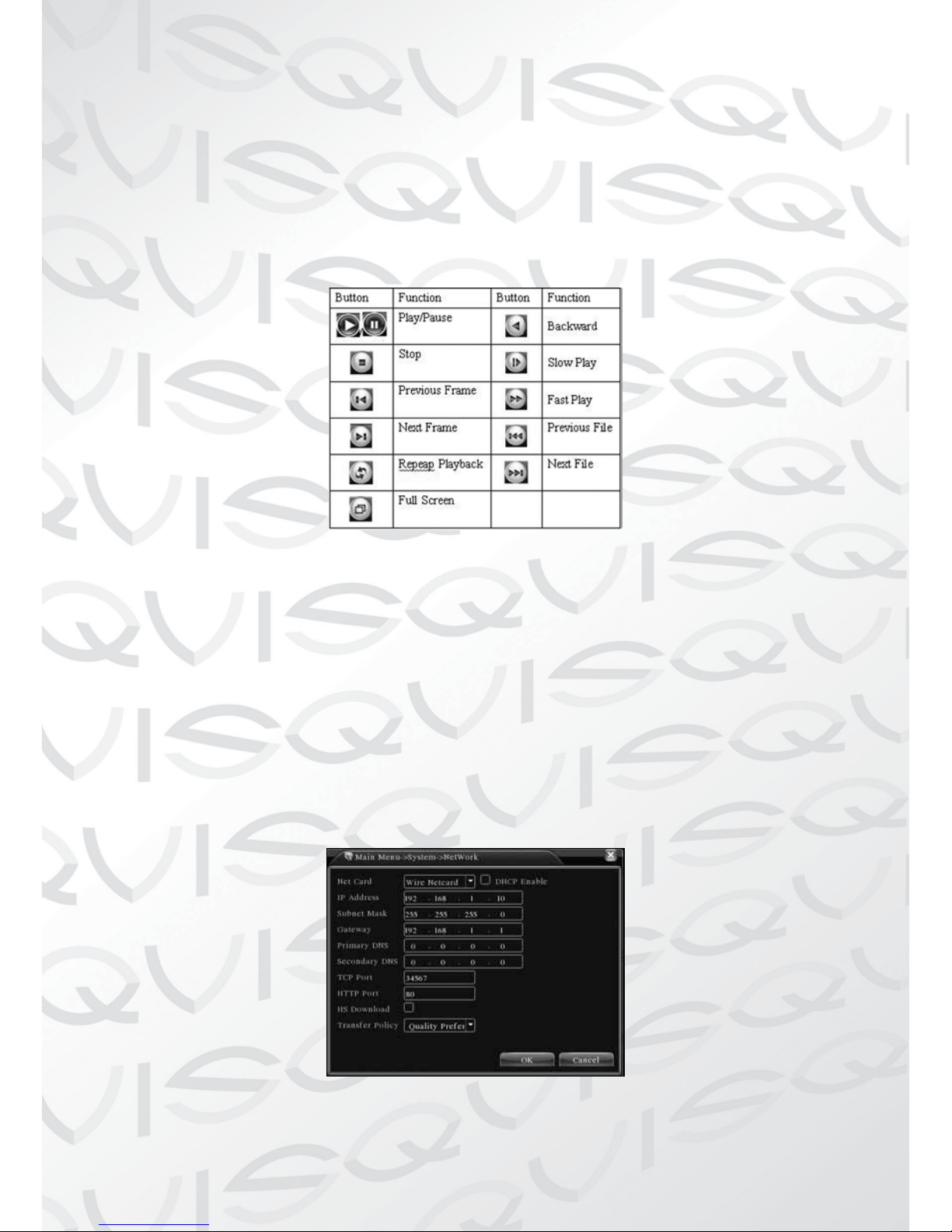
(Playback control) Refer to the following sheet for more information.
Table 2, Playback control key
Note: Frame by frame playback is only performed in the “pause” playback state.
Special functions:
Accurate playback: Input time (h/m/s) in the time column and then click
playback.
Local zoom: When the system is in single-window full-screen playback mode,
you can drag your mouse in the screen to select a section and then left click
mouse to activate the local zoom. You can right click mouse to exit.
9 Network Setup
Picture 5, Network Setup

Network setup through Main Menu>System>Network
(IP address) Set the IP address. Default: 192.168.1.10.
(Subnet Mask) Set the subnet mask code. Default: 255.255.255.0.
(Gateway) Set the default gateway. Default: 192.168.1.1.
Enter the equipment’s IP address and the router in the same network segment.
For example, if the router IP address is 192.168.1.1, and the subnet mask is
255.255.255.0. According to the default setup, generally the default gateway
is the router IP address, so if you enter the IP address 192.168.1.10 in the IE
browser to achieve visiting LAN equipment such as operating image surveillance
in the public network remote access equipment for monitoring.
Detail setup refers to “Network setup reference”.
10 Alarm Setup
Picture 6, Motion Detection
Motion detection setup. Set the DVR equipment to making it alarm, linked
recording and make the PTZ turn to a preset position where there is a moving
object in a designated areas during Monday to Friday.
Step 1. Choose (Main Menu) > (Alarm) > (Motion Detection), then enter the
setup interface;
Step 2. Choose one channel and adjust the sensitivity level, then set the time
period of the alarm surveillance. Set the monitor area (click the “set” button,
choose the areas you want, and the “default” means choose all areas, then right
click to choose “up window”.
Step 3. When in the alarm state, the DVR can show linked measures. Alarm
output, recording, tour, PTZ activation, snapshot, show message, sending email
and buzzer.
Step 4. Set the other channels alarm parameters following steps 2 and 3.
Note: video block, video loss and alarm input’s setup method are similar with
motion detection.

11 PTZ Control
Easy set up to do PTZ operations.
Step 1. Set the basic parameters such as channel and protocol. (Main Menu)
>(System) >(PTZ Cong)
Step 2. At this state of the menu preview, enter the PTZ operation menu.
Step 3. “right click” the mouse, and choose the “PTZ control” to set the PTZ
general operations. The other method is “right click” the mouse and choose
“High Speed PTZ”. Click the left button and move it to control the PTZ direction
of travel. Use the mouse wheel to zoom in/out with the controlled camera.

Part 2: Remote Control
1 Network Connection
Before web operations, you need to connect the equipment to the internet.
Step 1. Connect the equipment with the internet correctly.
Step 2. Setup the LAN as in Part 9, Network Setup in the rst part of the
reference manuals.
Step 3. When the Lan is connected, it needs to set up port mapping for public
network access.
Step 4. DDNS Application. You can apply for the DDNS at http://www.3322.
org/ or http://www.oray.com/
Step 5. DDNS Setup. Make sure to ll the right info in the Main Menu>System->NetService->DDNS
Note: The device must be in the same network as the PC, if it fails to connect,
please check the device IP is working.
2. Remote Monitoring
After connecting to the network, there are two methods that can be used for
remote monitoring: they are client software and common browser.
Client software (CMS) is professional software used in multi-equipment
monitoring, which is safe, convenient and stable. It is the best choice and we
advise customers to use it. The browser comes with systems such as IE browser.
2.1 Client software
CMS software is used in a computer, and manipulates several DVR’s at the
same time.
Step 1. Please download the CMS software from our website at
http://qvissecurity.com/support/downloads.aspx
The CMS software will be found in the lower left corner of the page under the
heading LX DVR Series --- Remote viewing software
Step 2. After installing this software on your local PC, then open the operation
system as in picture 6, enter the add device interface through (System)
>(Device Manager) >(Add area/device), and enter the DVR information which
is needed following the prompts, in that way, you can manipulate any specied
equipment. The method is the same with web manipulation.
Step 3. You can add several DVR’s by repeating this operation.

Picture 7, CMS Interface
3. Basic Web Operation
Picture 8, WEB operation interface
Web operations in picture 8, web operations interface.
1) Screen Split
Choose image preview mode;
2) Playback
Enter playback mode, which supports multi-channel playing back simultaneously.
3) Log
Display log information,
4) Local Cong
Alarm and System setting
5) Channel operation
Open the videos. Left click and choose a window in the left, and choose the
corresponding channel in the right, then double click the video. Open the second
channel’s video, choose the left window, then select the corresponding channel
in the right, after then, double click the video.

Opening other channels is the same way. If you have chosen the window of
opened video, then open other channels in the right, the system will close all
the channels and open new channel. Customers can adjust image mode upon
opened video channels.
Close the channel. Rightclick mouse at the channels which are needed to close.
Or choose to close all the windows to close opened video channels.
Part 3: Special Functions
This series allows a more personalized design and visualization operation press
key, local enlargement in any areas of the preview interface, timing start up and
shut down, FTP upload, 3G&WIFI and so on. Now let’s introduce Encode, Multi
channels playback and mobile monitor setup.
1 Coding Cong
DVR achieves the functions such as high quality playback and remote monitoring
by coding parameter cong.
Picture 9 Encode setup
1.1 Encode setup for every channel
Note: Only part of DVR mode supports resolution switch.
Step 1. Local operation through (Main Menu) > (System) > (Encode) (remote
setup click right mouse and choose “cong” in (System) > (Encode) .
Step 2. Choose channel 1, set the resolution as D1 (25fps, 1536Kb/s)
Step 3. Choose channel 2, set the resolution as CIF (25fps, 512Kb/s). Click
right mouse or choose “Advanced” then click “Copy” button.
Step 4. Choose channel 3, click the right button or choose the local “Advanced”,
then choose “Stick”. Channel 4’s operation is the same with channel 3.
Step 5. Click “save”, then exit.
Note: standard parameter between resolution and Kb/s.
Resolution Kb/S
D1 512 - 2560 kbps
HD1 384 - 2048 kbps
CIF 64 - 1024 kbps
QCIF 64 - 12 kbps
1.2 Extra Stream Setup
Extra stream is used for remote client monitor and mobile monitor area.
Step 1. Enable extra stream
Step 2. Set frame rate and bit rates,operation way is the same as main stream.
2 Multi-channel Playback Simultaneously
These DVR’s introduce the latest combination of coding techniques to allow
videos to play on all channels simultaneously.
The 4 channel DVR can support 4 channels of playback simultaneously, the
8 channel DVR can support 8 channels of playback simultaneously, channel
numbers can be freely chosen.
Picture 10, Video Playback
Step 1. Set every channel’s encode parameter by (Main Menu) >(Record)
>(Encode) .
Step 2. Enter video playback interface, click Search button.
Step 3. Choose File Type and All and time period, then click OK in Search Con-
dition interface.
Step 4. Choose the record le, then click Play or double click the le to playback
in playback interface.

3 Multi-channel Real-time Monitor remotely
Introducing extra-stream techniques to achieve multi-channel remote monitoring simultaneously in the condition of narrow band (poor network speed)
Picture 11, CMS Interface
Step 1. Enable extra streams(MainMenu->System->Encode)
Step 2. Open CMS, and then login.
Step 3. After add devices, right-click a device name to select “Connect all video
(Main stream)”
4 Mobile Monitoring
See our website for the latest on mobile phone and tablet support.
5 Flexible File Storage and Backup
This DVR introduces several unique storage and backup techniques to achieve
multiple storage and backup modes.
Real-time storage
Redundant storage. DVR introduces RAID 1 storage technique to achieve two
hard disks simultaneously storing and mutual backup.
USB HDD and movable hard disks. The DVR introduces the storage technique,
supporting video les which are written in real-time to the storage devices.
DVD-RW. The DVR introduces the newest real-time storage technique, supporting video les which are burnt in real-time to a DVR.
Real-time remote storage. The DVR supports video les storing in real-time to
a computer devices (Disk C/D/E/F) at a remote client.

File download
Using a USB disk and a movable hard disk download to local device the DVR
supports the chosen les are backed up at high-speed to these storage devices.
DVD-RW. The DVR supports the chosen video le are burnt and stored as a CD.
Network high-speed download. DVR supports high-speed down loading of the
chosen le to a remote client.
Appendix 1. Remote controller operation
Serial
number
Name Function
1 Multi-channels button Multi-channels preview
2 Number button Password input/number input/ channel
switch
3 Esc Back to up window

Serial
number
Name Function
4 Direction button Direction and OK button
5 Playback operate Playback Basic operation
6 Record control Enter into record menu
7 Remote controller Input the number of DVR to control it
8 FN Assistant function
Appendix 2.Mouse operation
Operation Function
Double left click Double click one item in the le list to playback the
video
Double click the playback video to zoom in or out the
screen
Double click the channel to make it full screen display
in preview
double click again to resume the multi-channel display
Left click Choose according option in the menu
Right click Pop desktop shortcut menu in preview state
Current shortcut menu in the menu
Wheel button Add or subtract number value in the number setting
Switch the items in the combo box
Page up or down in the list
Move mouse Choose the widget or move the item in the widget
Drag mouse Set the motion detect area
Set the cover area
Please note:- This is a general user guide which covers all of our DVRs mentioned
on page 2. Each DVR has a more extensive user guide specic to that model and
can be down loaded from our website (www.qvissecurity.com).
The manual downloaded from our website will be the latest manual available for
that DVR and as such if there is a conict between this manual and the on-line
manual then the on-line manual will take preference.
 Loading...