


HDCVI-MB1
HDCVI-EYE1
1 Megapixel HDCVI Bullet & Dome Cameras
User’s Manual
V1.0 06 / 2014

i

ii
Welcome
Thank you for purchasing either the HDCVI Bullet or Eyeball Dome
cameras.
This user’s manual is designed to be a reference tool for the installation and
operation of your camera setup.
Here you can find information about the corresponding HDCVI camera’s
features and functions, as well as a detailed installation method.
Before installation and ope ration please read the following sa f e guar ds
and warnings carefully!

iii
Important Safeguards and Warnings
1.Electrical safety
All installation and operation here should conform to your local e lectr ical safety codes.
The power supply shall co nform to the requirement in the SELV (Safety Extra Low Voltage) and
must make sure that the limited power source is rated 12V DC or 24V A C.
Please note: Do not connect two power supplying sources to the devi ce at t he same t i m e; it
may result in device damage!
We assume no liability or respon si bility for all the fires or electrical shock caused by improper
handling or installation.
We are not liable for any problems caused by unauthorized modificat ion or attempted repair.
2.Transportation Security
Please ensure that the product does not endure heavy stresses, violent vibration or contact with
water during transportati on, storage and installation.
Please use the original packing material (or the material of the s ame quality) if you need to return it
to vendor.
3.Installation
Do not apply power to the product before completing installation.
Do not put object(s) on the product .
Please install a proper power cut -off device during the installation connection.
4.Qualified engineers needed
All the examination and repair w ork should be done by the qualified s er vice engineers. We are not
liable for any problems caused by unauthorised modificatio ns or at t empted repair.
5. Environment
This product should be installed in a c ool, dry place away from direct sunlight, inflammable,
explosive substances and etc.
Please keep it away from environments that cont ain electromagnetic rad iati on or objects that
produce it.
Please keep sound ventilat ion around the device at all times.
Do not allow the water and other liquid to penetrate into the device if casing has bee n
compromised. This series product com pl ies with the IP66 standard specified in the Degrees of
Protection Provided by Enclosure.
Ensure lightning surge prot ec t ion is in p lace to make sure you fully protect camera circuitry from
electrical overload.

iv
Please make sure the CCD (CMOS) component is away from the radiation of the laser beam
device. Otherwise it may result i n CCD (CMOS) optical component damage.
It is recommended that the grounding studs of the product should be grounded, so to further
enhance the reliability of the camera.
6. Daily Maintenance
Please shut down the device and then unplug the power cable before you begin any maintenance
work.
Do not touch the CCD (CMOS) optic component. Please use an air jet to clean the dust off the lens
surface. You can use the dry cloth with some alcohol or mild detergent to clear if necessary.
When the camera is not in use please put the dustproof cap to protect the CCD (CMOS)
component.
Do not use volatile solvent such as the benzene, paint thinner or detergent with the ability to
abrade surfaces. It may result in lens damage or adversely affect t he device’s performance.
7. Accessories
Always use all the accessories recommended by manufacturer.
Before installation, please open the package and check that all the components are included. Contact
your local retailer/vendor ASAP if something is missing.

v
Table of Contents
1 General Introduction..........................................................................................................1
1.1 Overview...................................................................................................................1
1.2 Features..........................................................................................................1
1.3 Functions ........................................................................................................1
1.4 Specifications..................................................................................................2
2 Framework and Dimensions...................................................................................4
2.1 HDCVI-MB1 ....................................................................................................3
2.2 HDCVI-EYE1………........................................................................................5
3 Installation ...................... ..... ..... ................................................................... ............6
3.1 HDCVI-MB1.....................................................................................................6
3.2 HDCVI-EYE1……............................................................................................7

© Copyright Qvis ®. All documentation rights reserved.
1
1 General Introduction
1.1 Overview
Our megapixel HD camera con forms to the HDCVI standard. It support s high speed transfer of video
signals over long distance transmissions without an y delay. It can be controlled by a DVR that also
conforms to the HDCVI standard.
One of the other main features t his camera includes is the IR night vision, which aids in video surveilla nce
when the camera is functioning within a low illumination environment. The LED IRs highlight ob ject s of
interest within the camera ’s field of view and is then able to filter out any visual interference so that you can
easily view footage upon a monitor . I t suppor t s r eal-time monitor and listeni ng at the same time via the
inbuilt microphone. If you w ant to communicate with a person(s) i n view of the camera it also supports dualway bidirectional talk.
The built-in protection enc losure and waterproof design con forms to the IP 66 level. It has the sound
waterproof function suitable for use in the outdoor environments.
1.2 Features
• High-performance CMOS image sensor, which produces megapixel quality definition.
• HD video, coaxial cable to trans m it t he control signal.
• Supports 75-3 coaxial cable t r ansmission without any loss. Transmission distance is over 500m.
• High speed, long distance r eal-t ime transmission.
• Supports ICR switch to allow for surveillance in both the daytime and at night.
• Supports auto exposure, aut o w hit e balance, auto electronic shutt er and aut o gain function.
• Supports DC12V power supply.
• IP66 compliance.
• Supports intelligent IR function.
1.3 Functions
HDCVI Specification
HDCVI (High Definition Composite Video Interface) is an over-coaxial-cable HD video tr ansmission
standard. The technology r ender s two HD video formats by progres siv ely scanning the signal.
ICR
The IR cut removal feature filters the IR light in the daytime and then auto switches to the gener al filter at
night. This function allows t he c amera to output balanced and clear video.
Smart IR technology
The sensor controls the IR light and can switch it on/off via hardwar e and software working in combination,
which can automatically provide IR light compensation according to the environment i llu m ination conditions.

© Copyright Qvis ®. All documentation rights reserved.
2
Auto gain function
This outputs the standard video signa l under different illumination environ men t s. The amplifier can
automatically adjust within a wide range. The system can enhance the camera sensitivity in low illu m ination
and enhance the video signal output to produce clear and high definition video.
Auto white balance
This function allows the cam era to automatically adjust t he color temperature of the video fo ot age if the
camera is either in an indoor and outdoor environment, just like our human eyes does.
Auto exposure
System can automatically set the shutter speed and iris value according to the snapshot video expo s ur e
conditions.
Auto electronic shutter
The system can automatic ally adjust the electronic shutter w hen t he environment’s light changes.

© Copyright Qvis ®. All documentation rights reserved.
3
1.4 Specifications
1.4.1 Performance
Please refer to the following she et for network camera performance specification:
Parameter
HDCVI-MB1
HDCVI-EYE1
Video Processor
1/2.9" 1.0 Mega Pixels CMOS
Video Format
PAL/NTSC
Effective Pixel
1280 (H) x 720 (W)
Min Illumination
0.01Lux @ (F1.2,AGC ON), 0Lux with IR
Electronic Shutter
PAL:1/50s~1/100,000s NTSC:1/60s~1/100,000s
Video Standard
HDCVI compliant
Video Frame Rate
PAL:1280×720@25 fps NTSC:1280×720@30 fps
Lens Port
M12
Lens Type
2.8/3.6/6/8mm optional
Day/Night Switch
ICR mechanic auto switch
Sync Mode
INT
Video Output
1-channel HDCVI high definition video output
White Balance
Auto
Gain Control
Auto
BLC
Auto
IR Light Control Plan
Advanced non-photosensor control plan
Transmission Distance
Over 500m via 75-3 coaxial cable.
Smart IR
Supported
Max IR Distance
20m
Protection Level
IP66
N/A
Working Temperature /
Humidity
-30 ~+60
℃℃
. Humidity is less than 95%(no condensation)
Power
DC 12V±10%
Power Consumption
3.5W MAX
(Input: 12V 0.29A)
2.5W MAX
(Input: 12V 0.21A)
Dimensions (mm)
φ65.0×154.7
φ113.6×85.4
Weight
380g
200g
Installation Mode
Wall Mount
Wall mount /in-ceiling mount

© Copyright Qvis ®. All documentation rights reserved.
4
2 Framework & Dimensions
2.1 HDCVI-MB1
Please refer to the following figures for dimension information. The unit is mm. See Figure 2-1 and Figure
2-2.
Figure 2-1
Figure 2-2
Please refer to the following sheet for detailed information.
SN
Name
Function
1
Double-circle glasses
Protective lens, sensitive optical part. Do not touch.
2
Lens
This is to allow the optical light from the environment into the
camera.
3
IR Lights
These are to send out the IR compensation light to enhance
the night vision.
4
Device body
This is the main supporting part of the camera. It includes
sunshield cap, front cap, rear part, bracket, etc.
5
Power input port
Connect to the DC 12V power supply.
6
Video output port
• BNC port: This is to output the HDCVI v i deo signal.
• You can connect to the devices such as the DVR or the
NVS conforming to the HDCVI specifications.
© Copyright Qvis ®. All documentation rights reserved.
5
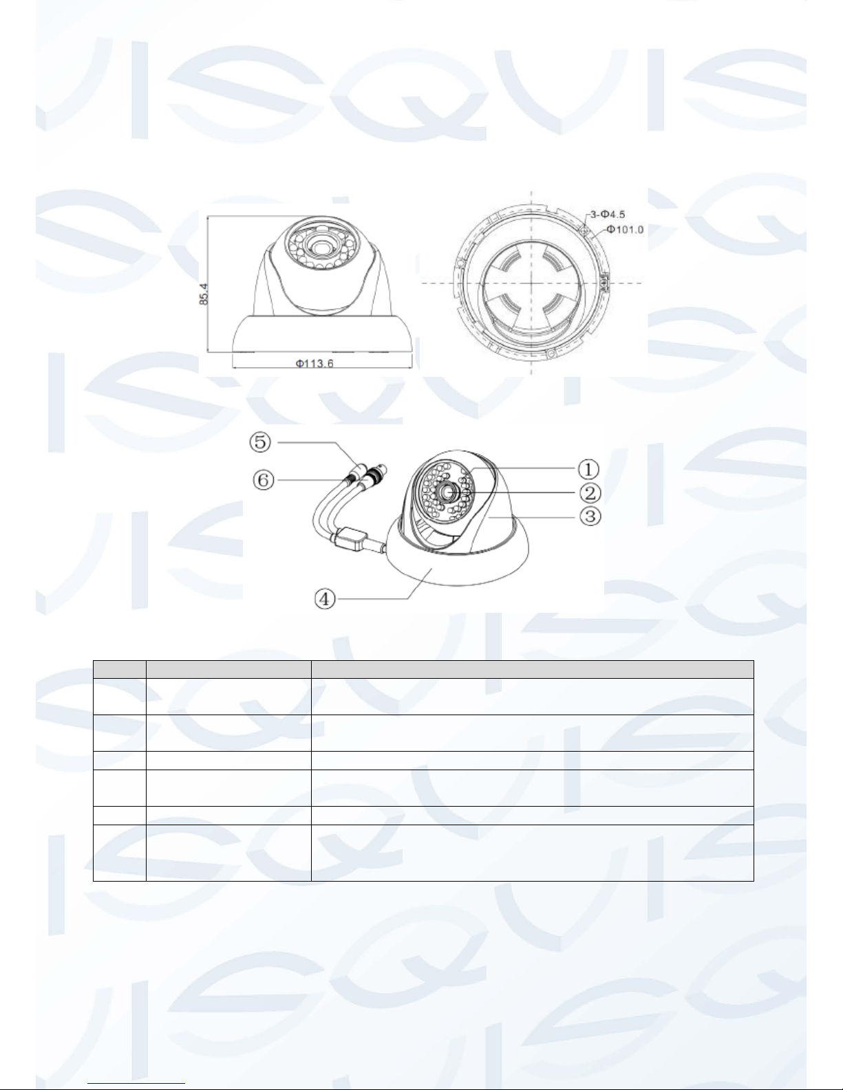
2.2 HDCVI-EYE1
Please refer to the following figure for dimension information. The unit is mm. See Figure 2-3
and Figure 2-4.
Figure 2-3
Figure 2-4
SN
Name
Function
1
IR Lights
These are to send out the IR compensation light to enhance
the night vision.
2
Lens
This is to allow the optical light from the environment into the
camera.
3
Device body
This is the main supporting part of the camera.
4
Camera Dome
decoration ring
Allows installer to fix camera to surface.
5
Power input port
Connect to the DC 12V power supply.
6
Video output port
• BNC port: This is to output the HDCVI video signal.
• You can connect to the devices such as the DVR or the
NVS conforming to the HDCVI specifications.

© Copyright Qvis ®. All documentation rights reserved.
6
3 Installation
Important:
Please make sure the inst al l at i on surface can support a minimum of 3X weight of the camera and
the bracket.
3.1 HDCVI-MB1 (Bullet Camera)
Step 1:
Drill three holes into t he in s t allation surface (wall or the ceiling). I nser t t hr ee expansion bolts into the three
holes and then lock firmly. See Figur e 3-1.
Figure 3-1
SN
Item Name
1
Installation Surface
2
Bracket
3
Screws
4
Cameras
Step 2:
First prepare the cable accor ding to the cable requirements. Li ne up t he three screw holes at the bottom of
the bracket with the three installation holes in the wall or the ceilin g, and then insert three screws into the
three holes on the chassis of the br acket and fix them firmly. Now secur e t he bracket onto the installation
surface of the wall or the ceilin g.
Step 3:
Adjust the camera to point in t he direction of the desired monitor ar ea via the three directions indicat ed i n
Figure 3-2 after you fixed the camera into place.

© Copyright Qvis ®. All documentation rights reserved.
7
Figure 3-2
Step 4:
Connect the device’s video output port to the DVR device. Then connect the power cable to the device.
Now you have completed the device installation and cable conn ect ion. You can use the terminal enc oding
device to monitor the video footage produced by t he cam er a.
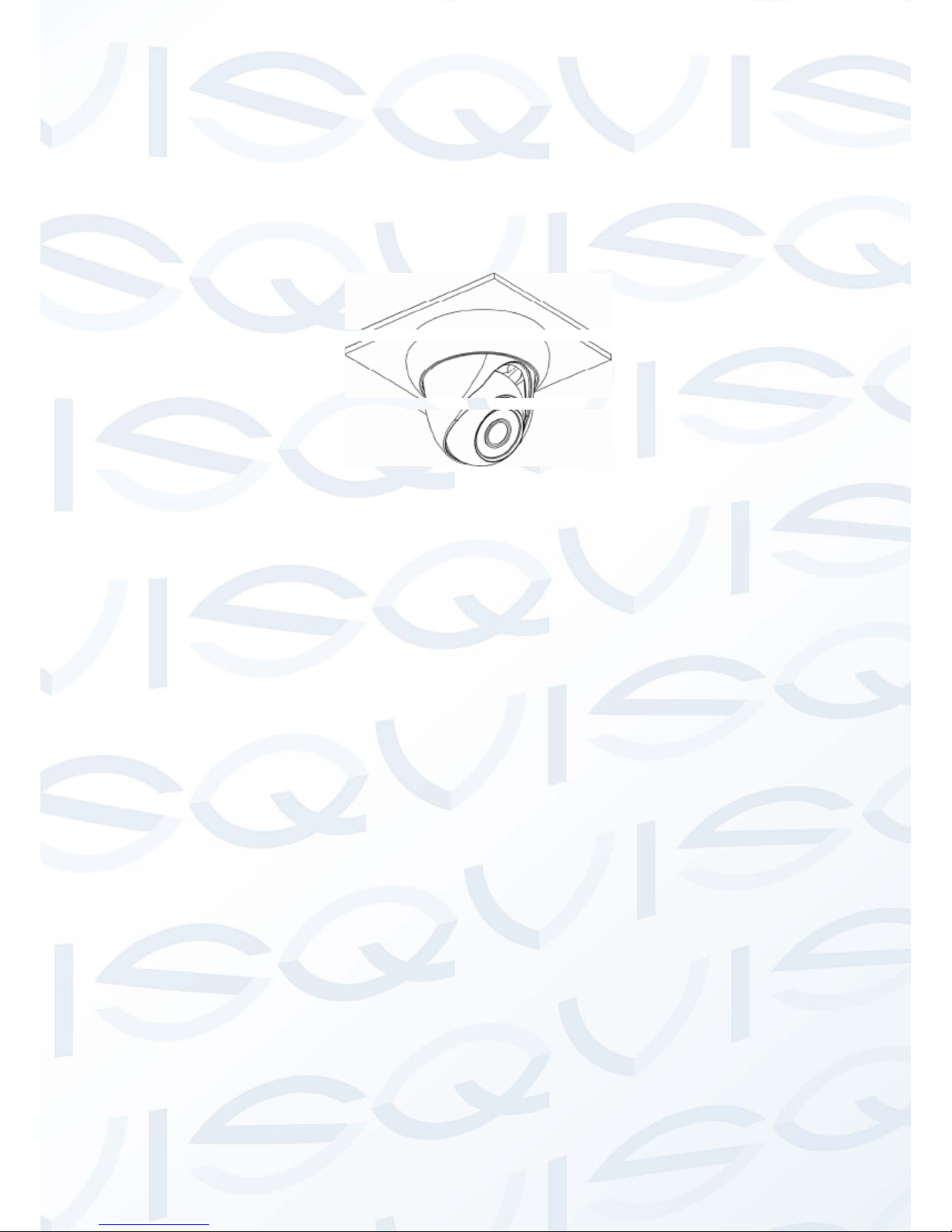
3.2 HDCVI-EYE1 (Mini Dome Camera)
The dome camera is suited to a ceil ing location installation. But it can also be installed onto a wall or other
flat surfaces if required.
Step1
Please take the installation position map in the accessories bag, and then paste it on the ceiling or the wall
according to your monitoring area r equirements. Draw and then drill three holes into the installation surface
and then insert three expansio n bolts into the holes. Secure these three bolts firmly.
Step 2
Turn the decoration ring count er clockwise to remove it. Please dr il l a “ cable exit hole” in the surface
according to the installatio n position map, if you want to draw out the cable from the top of the installation
surface. You need to draw out the cable from the cable channel s ide port on the pedestal if you want to
lead it away from the camera. Adj us t t he device’s installation pedestal to the proper position and th en draw
the cable through the cable exit. Line up the three screw holes in the device pedestal to the three plastic
expansion bolt holes in the insta ll at ion position. Put the three self-tap ping screws in the three plastic
expansion bolts firmly. No w t he dom e c amera is secure in the installat ion s ur f ace. See Figure 3-3
.

© Copyright Qvis ®. All documentation rights reserved.
8
Figure 3.3
Step 3
Adjust the lens to get the clearest monitor video quality. See Fig ur e 3-4. Use a crosshead screwdriver to
loosen the screw and the turn the camera body to the proper position ma nually. Fix the screw again.
Important:
Do not remove the screw. Only loosen it a little. Please secure after y ou com pl et ed t he setup.
Figure 3-4
© Copyright Qvis ®. All documentation rights reserved.
9
Step 4
Line up the bulge of the decoration r ing to the nick found on the camer a body and install along the tilt
installation. Push and then turn decoration ring clockwise. Th e installation is complete after you secure the
decoration ring. You need to use the proper tool to open up the side port for the U-cable channel from the
decoration ring if you want t o dr aw out the cable from the side port of the cable channel when you are
installing the device cable. Then you can draw out the cable from th e cable channel of the pedestal. Finally
you can install the decoration ri ng t o complete the installation. See Fig ur e 3-5.
Figure 3-5

© Copyright Qvis ®. All documentation rights reserved.
10
For more information about our other Analogue Cameras and other
available HDCVI equipment, DVRs, NVRs & accessories, please visit
our website:
www.adata.co.uk
Alternatively scan this QR code with your smart phone to be directed
instantly to our website:
 Loading...