

Page 1

Q V i d i u m® T E C H N O LOGIES, INC.
QVidium QVARQ A140 Rx Proxy
Model #QVAM140-ARQ
For Amino 140 IPTV SetTop Box
User’s Manual v.2
December 8, 2013
Rx Proxy Software Version 10
2011-2013 QVidium® Technologies, Inc.
12989 Chaparral Ridge Road, San Diego, CA 92130
Phone 858.792.6407 • Fax 858.792.9131
Page 2

User’s Manual v.2 QVidium® QVARQ A140
Table of Contents
1 Network Configuration ......................................................................................... 3
2 Receive Proxy
2.1 Receive Proxy Overview
2.2 Receive Proxy Network Configuration
2.3 ARQ Packet Transport & Error Correction
2.4 Server Mode
3 Troubleshooting
3.1 Troubleshooting – Common Problems
4 Appendices
4.1 Appendix A: Receive Proxy Configuration Parameters
........................................................................................................ 5
................................................................................ 5
.......................................................... 5
................................................... 7
................................................................................................... 10
.................................................................................................. 11
....................................................... 11
........................................................................................................... 12
........................... 12
2 of 13 - Copyright 2011 QVidium® Technologies, Inc.
Page 3
User’s Manual v.2 QVidium® QVARQ A140
1 Network Configuration
The Amino A140 SetTop Box is, by default, preconfigured to obtain its IP address through DHCP.
The following instructions will help you determine its IP address and allow you to set a static IP
address.
1. Download and install QVidium’s CodecManager Application in a Windows PC
a. Go to http://www.qvidium.com, click on Support
b. Scroll towards bottom. Click on “QVidiumCodecManager-7.msi”
(http://www.qvidium.com/downloads/files/QVidiumCodecManager-7.msi)
2. Connect break-out cable or HDMI cable to connect A140 to a video monitor. (HDMI is
recommended, but you can connect to component or composite outputs as well.)
3. Connect the PC and the A140 via Ethernet cables to two ports on the same Ethernet
switch. (Do not use cross-over cables.)
4. Connect A140 power adapter to A140 and plug into an AC power source
5. Wait for QVidium splash screen to briefly appear on monitor.
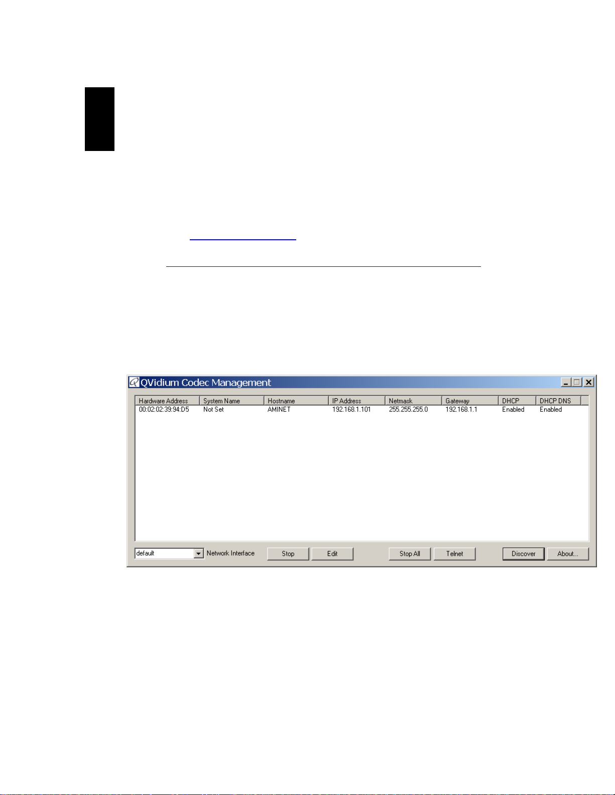
6. Start Codec Manager.
a. You should see something like the following:
b. If you do not see an entry for AMINET then you may need to set a different
“Network Interface (low left corner pull-down menu)” and click Discover.
7. You should see the IP address as part of the entry for the Amino A140 (AMINET).
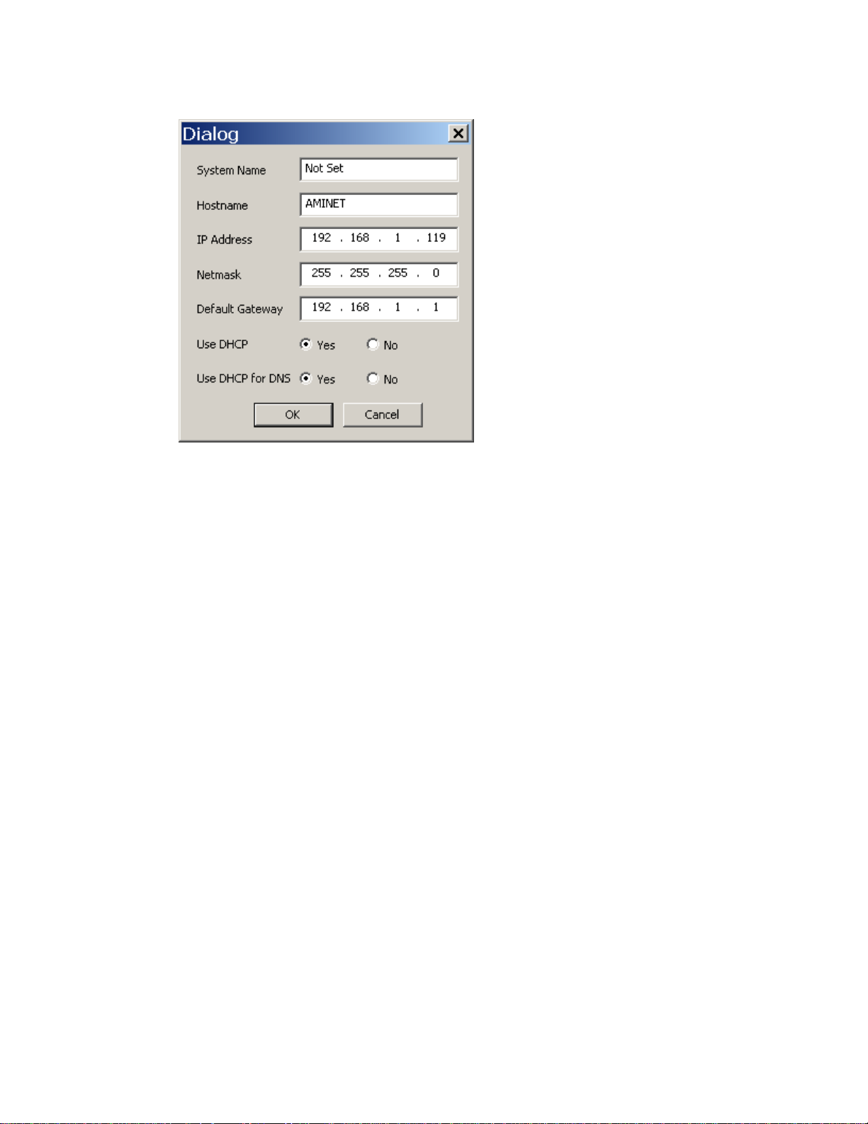
8. To change the IP address to a static IP address, click Edit. Fill in the desired settings and
click OK. To set a static IP address, you need to set “Use DHCP” to No. If this is on a
local area network (LAN), then you can leave the Default Gateway blank.
9. After clicking on OK, the A140 should automatically reboot for the new settings to take
effect.
3 of 13 - Copyright 2011 QVidium® Technologies, Inc.
Page 4
User’s Manual v.2 QVidium® QVARQ A140
4 of 13 - Copyright 2011 QVidium® Technologies, Inc.
Page 5

User’s Manual v.2 QVidium® QVARQ A140
2
2.1 Receive Proxy Overview
QVidium has created a special version of its patented QVARQ RX Proxy Error Correction software
for the Amino A140 Set-Top Box video decoder, and has added this QVARQ receiver proxy
software, along with a web interface, to the Amino A140 that we sell as Model #QVAM140-ARQ.
This ARQ receive proxy software, when started, runs alongside the default Amino software to
intercept an incoming ARQ packet stream, process the error correction to restore lost packets,
correct the incoming stream timing, restore the correct packet ordering, and then forward the
corrected video data stream to the internal Amino decoder for outputting to your monitor.
The Proxy menu controls the configuration and operation of this QVARQ RX Proxy software. This
section explains how to use the Web pages to configure the receive proxy parameters through three
profile web pages: Network Configuration, ARQ Configuration, and Server Configuration, as
described below and shown in Figures 3 through 6.
2.2 Receive Proxy Network Configuration
Figure 3 shows the Receive Proxy network configuration page. To configure the IP network
parameters, within the Network Parameters section of the proxy profile, set the UDP port and ARQ
port for the incoming stream. The proxy receives the video and audio IP streams as RTP/UDP IP
packets. The RTP header adds a timestamp and packet sequence number before inserting the
MPEG-2 transport stream packets into the RTP/UDP/IP packet payload.
The network interface to the receive proxy includes QVidium’s patented synchronized network jitter
buffering mechanism to help remove the effects of variable network delays. In the receive proxy
network interface. You may specify a delay for this jitter buffer in milliseconds. When processing
and ARQ packet stream, the receive proxy software inserts a jitter buffer that holds the specified
number of milliseconds of packets to give the decoder ample time to account for random delays,
and to allow the decoder to correct packet ordering. The receive proxy uses RTP sequence
numbers of incoming packets to insert incoming packets into their proper place in the de-jitter
buffer before releasing those packets into the receive proxy. The jitter buffer also uses the RTP
timestamp to synchronize the receive proxy’s network clock with the video source to adjust the
jitter buffer hold time.
In Auto ARQ Mode (selected by default on the ARQ configuration tab), the value you set for the
Jitter Buffer becomes a minimum value, since the receiver proxy software will ping the sender to
automatically determine the network jitter and over-ride the jitter buffer setting to a larger value if
necessary.
The following procedure will help you configure the network portion of the receive proxy:
1. Enter http://IPAddress where IPAddress is the IP address of the Amino 140 SetTop
Receive Proxy
Box
2. Click on “Profile” under the “Proxy” item from the menu on the left. The “Proxy
Profile” interface should display in the main area to the right of the menu system, as shown
in Figure 3. NOTE: You can only configure a RX Proxy module that has been registered
with a valid license. If uncertain about the license state, please click on “Register”. To
obtain a license key that you have purchased, please e-mail QVidium at info@qvidium.com
with the 32-digit license code. Without this code we cannot issue you a license key.
5 of 13 - Copyright 2011 QVidium® Technologies, Inc.
Page 6

User’s Manual v.2 QVidium® QVARQ A140
3. On the Proxy/Profile Network configuration page, enter the source UDP Port to match the
UDP port of the incoming IP media stream. The Jitter field is defaulted to 50 ms and can be
let at this setting..
4. Enter the Source ARQ port to match the UDP port set on the transmitting side (QVidium
Encoder or TX Proxy Server) for the ARQ packets of the incoming IP media stream. If
connecting to a TX Proxy Server or if the encoder is sending to multiple destinations, then you
will need to use a different UDP port number for the ARQ stream from the incoming UDP
media stream.
Figure 3: Rx Proxy Network Configuration.
6 of 13 - Copyright 2011 QVidium® Technologies, Inc.
Page 7

User’s Manual v.2 QVidium® QVARQ A140
2.3 ARQ Packet Transport & Error Correction
The QVidium QVARQ Rx Proxy features some of the most powerful and advanced error correction
capabilities found in any video over IP product. The QVidium QVARQ Rx Proxy implements
QVidium’s patented ARQ error correction and clock synchronization (US Patents #7,551,647 and
#7,522,528) for the more robust video transmission with the lowest delay. QVidium’s ARQ
(Automatic Retransmission Request) is a dynamically adjusting feedback error correction
mechanism designed specifically to enable the highest quality video transport over wireless
networks and the Internet. ARQ senses packet loss at the receiver and requests replacement
packets from the server. ARQ can provide nearly flawless reproduction of a video stream even
through extremely lossy or congested networks.
In contrast with FEC, QVidium’s ARQ is a feedback mechanism that detects packet loss at the
receiver and requests the retransmission of only those lost packets from a video source. A userconfigurable buffer at the receiver (decoder) delays the video stream just long enough to allow the
system to replace any missing packets and re-insert them in their proper order without disturbing
play out of the video stream. Because ARQ senses actual packet loss, rather than attempt to
predict packet loss, it can precisely and completely restore all lost packets without disturbing timing
of the video play out. In contrast to FEC, ARQ can successfully recover lost packets regardless of
the magnitude or pattern of the packet losses, provided that the network connection has enough
capacity to send both the original video stream and the replacement packets.
ARQ shares similarities with robust packet transport protocols, such as TCP/IP in that both use
feedback to create robust network packet transport. However TCP/IP uses a sliding window that
limits the number of packets that a source can have in transit and requires a positive
acknowledgement for each window of packets. This limits TCP’s throughput, especially over links
with long latencies. Furthermore, under heavy loss conditions, TCP/IP scales back the data
transmission rates and provides no concise deadlines or constraints on packet delivery times. For
real-time video, this limits the usefulness of TCP/IP and makes it unacceptable for live, low-latency
video transport.
In contrast with TCP/IP, QVidium designed its patented ARQ error correction specifically for live,
interactive, real-time video and audio signals to automatically recover nearly all lost packets with
minimal latency and over nearly any link loss conditions. It adds a small configurable amount of
delay to the network transport in exchange for significantly improving the robustness and reliability
of video transport.
This section explains how to configure the video transport capabilities of the QVidium QVARQ Rx
Proxy and how to enable ARQ error correction.
2.3.1
Automatic Retransmission Request (ARQ) tries to recover any packets lost during transport to the
decoder by adding a small amount of delay at the decoder during which time the decoder would
have time to detect and request any missing packets. The size of this delay should also include
adequate time for the missing packet to be received and inserted into the play out queue so that
the video stream can continue to flow smoothly and unimpeded to the MPEG decoder.
To enable ARQ, you must first select ARQ transport from the Profile dialog. ARQ transport
must also be enabled at this receive proxy. With ARQ selected and the encoder started, the
encoder will begin to save outgoing packets for later retransmission, when necessary. You must
also be certain to configure any firewalls to allow the ARQ retransmission request packets through.
The default port for these upstream ARQ request packets is UDP port 7020, although you can
ARQ Operation
7 of 13 - Copyright 2011 QVidium® Technologies, Inc.
Page 8

User’s Manual v.2 QVidium® QVARQ A140
configure this to any other valid, non-conflicting UDP port. However, if you choose to change the
ARQ request port, you must make certain the settings at the encoder and decoder match.
At the receive proxy, the ARQ error correction mechanism first buffers incoming packets in a
synchronized network de-jitter buffer that maintains a constant, configurable delay for incoming
packets. The de-jitter buffer processes RTP sequence numbers and reorders packets as
necessary to restore proper packet sequence and to buffer against erratic network delays. Its goal
is to output a smooth, consistent flow of packets with increasing sequence numbers. This output
feeds the ARQ error correction mechanism.
The ARQ unit at the receive proxy watches for gaps in RTP sequence number from the de-jitter
buffer output, and immediately sends out retransmission requests when necessary. Incoming
retransmitted ARQ packets bypass the de-jitter queue and find their correct place in the ARQ
buffer, so that by the time packet are output by the ARQ buffer, the ARQ error correction
mechanism should no longer contain any missing packets.
When the encoder and decoder are both started, the receive proxy automatically measures the
round-trip delay and packet jitter to the encoder and automatically configures ARQ for optimal
operation according to a few basic user-specified parameters, as described in Section
Note: For ARQ error correction to be enabled, you must select ARQ transport at both the encoder
or video source and this receiver proxy. The encoder/video source must be configured to allow
upstream ARQ request packets to the source. If you set the ARQ port equal to the UDP port, then
for most firewalls QVidium’s ARQ will automatically configure the firewall to allow in the upstream
ARQ requests.
8 of 13 - Copyright 2011 QVidium® Technologies, Inc.
Page 9

User’s Manual v.2 QVidium® QVARQ A140
Figure 4: Rx Proxy ARQ Error Correction Configuration.
2.3.2
The configuration page for ARQ is shown above in Figure 4. To enable ARQ, you must first select
ARQ transport from the Profile dialog. Also, ARQ transport must be enabled at the encoder.
With ARQ selected and the decoder started, the decoder will watch for gaps in the RTP sequence
numbers from the output of the jitter buffer. When it detects missing packets, it sends
retransmission requests to the encoder so that the encoder can quickly resend any missing
packets. Incoming retransmitted ARQ packets bypass the network de-jitter queue and find their
correct place in the ARQ buffer, so that by the time packet are output by the ARQ buffer, the output
of the ARQ buffer should no longer contain any missing packets.
The ARQ has five parameters that can be configured in manual mode: Target Latency, Burst
Drop, Robust Mode, Number Retries, and Round Trip Time. In automatic mode, the
system automatically measures and calculates the Round Trip Time and Number Retries. In
most cases automatic mode using the default parameters should be adequate.
Of the required parameters, the first parameter, Target Latency, specifies the total delay, in
milliseconds, allotted for the request, retransmission, and recovery process. The ARQ mechanism
will attempt as many retries as possible within this target latency time. Thus, larger target latency
times increase the delay before video is output, but allows for more chances of requesting and
recovering any missing packets.
A Burst Drop delay can also be specified to delay any retransmission requests for a time equal
to the maximum expected packet loss time, such as from dynamic router changes of other sources
of burst loss.
A Robust Mode can also be selected. When selected (checked), a minimum of two tries will be
attempted for recovering any missing packets. When not selected (unchecked), ARQ will always
try at least once to recover any missing packets.
To help with firewall configuration and to handle potential port conflicts, the user can change the
default port that ARQ uses to send upstream retransmission requests, ARQ Port. However, you
must make certain that the same ARQ port number is set in both the encoder as in the decoder.
Although the automatic measurement of the round-trip time uses multiple measurements to take
into account random network delays, for some networks you might wish to specify a larger roundtrip value, or to specify a larger number of retries in case the upstream link loses some of the
retransmission request messages. In automatic robust-mode of ARQ operation, the system
automatically measures the round-trip time and divides that number into your specified Target
Latency to determine the number of retries to use. However in Manual Mode, you can force ARQ
to always use a specified number or retransmission requests.
NOTE: Remember to click Save after changing any parameters, or your changes will be lost. You
also have to click Start for any changes to take effect.
ARQ Error Correction Configuration
9 of 13 - Copyright 2011 QVidium® Technologies, Inc.
Page 10

User’s Manual v.2 QVidium® QVARQ A140
2.4 Server Mode
In addition to passively listening for a stream that you would push from a media source, you can
also set the receiver proxy to be in Server Mode where it pulls a stream from a QVidium encoder
or even another QVidium TX Proxy Server. In Server mode, when you start the receive proxy it
remotely start a QVidium encoder and initiates a video stream. To put a QVAVC encoder in server
mode, simply leave the Destination IP Address blank and Start the encoder. This will cause the
encoder to listen for a start packet from the receive proxy.
To have the receive proxy initiate a stream in Server mode, go to the Server tab and configure the
following parameters, as shown in Figure 5, below.
1. Click ‘Yes’ under “User Server” so that Server mode will be enabled when you next start the
proxy receiver.
2. Enter the IP address or hostname of the media source you want to pull the stream from.
3. Set the Echo Port to match the echo port on the media source. Normally the echo port has a
default value of 7. You should keep this value at the default of 7 unless you have reason to
change it and you have also changed the corresponding entry on the video source.
4. Click Start on the receive server to restart it in Server mode.
Figure 5: Rx Proxy Server Mode Configuration.
10 of 13 - Copyright 2011 QVidium® Technologies, Inc.
Page 11

User’s Manual v.2 QVidium® QVARQ A140
3
3.1 Troubleshooting – Common Problems
No response from web browser or cannot ping system
Troubleshooting
1. Make certain that device is powered on and connected to your network.
2. Check that green LAN light in front is lit and link light at RJ-45 port is on.
3. Make certain that device is on the same subnet as the computer you plan to connect to.
(Either use a cross-over Ethernet cable to connect directly to the computer or connect
through the same switch as your computer.)
11 of 13 - Copyright 2011 QVidium® Technologies, Inc.
Page 12

User’s Manual v.2 QVidium® QVARQ A140
4
4.1 Appendix A: Receive Proxy Configuration Parameters
Appendices
This section explains the parameters related to the setup and operation of the receive
proxy, the error correction algorithms, and network transport configuration.
Network Parameters
The fields below relate to Ethernet/IP video transport settings.
IP Transport: This selects the type of video IP packet decapsulation and error correction
expected by the codec in receiving a Video/IP stream.
ARQ uses QVidium’s patented error correction mechanism for lost packet
recovery. ARQ encapsulates the video stream as a standard MPEG-2 Transport
Stream as the payload of UDP packets with an RTP packet header as per
RFC2733. It relies upon an upstream channel on UDP port 7020.
RTP disables all error correction mechanisms, but still allows measuring packet
loss.
UDP Port: This specifies which UDP port number (P), base 10, to listen on for the
Video/IP stream.
Jitter: Packets in incoming IP packet streams may lose their ordering or suffer variable
delays during transport through an IP network. The proxy receiver buffers all incoming
video/IP packets in a buffer and reorders RTP encapsulated packets by RTP sequence
number. This parameter specifies the size of this incoming packet buffer in milliseconds of
delay. Specify 0 here to disable this additional buffering when latency needs to be
minimize.
ARQ Parameters
The parameters below ONLY pertain to QVidium ARQ error correction. They will be
ignored unless ARQ is selected for IP Transport.
Target Latency: QVidium’s ARQ error correction operates through the addition of a
small additional buffering delay to provide enough time to request and receive
replacement for each lost packet. Target Latency gives the ARQ mechanism a target value
for determining the necessary ARQ delay. The ARQ divides the Target Latency, specified
in milliseconds, by the round-trip time to the video encoding source to determine the
number of request attempts. Unless Robust Mode is enabled, it sets a minimum ARQ
latency of one round-trip time. A larger Target Latency allows the system to increase the
number or repeat requests.
12 of 13 - Copyright 2011 QVidium® Technologies, Inc.
Page 13

User’s Manual v.2 QVidium® QVARQ A140
Max Burst Drop: Burst packet losses are common occurrences in many IP networks and
the Internet. IP networks may dynamically change paths in response to load balancing,
link failure avoidance, and for other reasons. During a re-route, a sequence of queued
packets on a discontinued path may be dropped. A burst of packets may be dropped when
higher priority packets stall a lower priority buffer. ARQ will notice a burst packet loss
when the first packet after the loss arrives at the codec. Setting the Max Burst Drop Delay
(in milliseconds) will delay the ARQ repeat request by this amount to handle packet burst
losses.
Robust Mode: Normally, the ARQ will only require that a minimum of one repeat request
is sent to the video encoding source device, regardless of the Target Latency. However,
enabling Robust Mode will increase the minimum number of repeat requests to a minimum
of two retries.
ARQ Port: By default, ARQ normally sends upstream retransmission request packets on
UDP port 7020. You can change this ARQ Port setting to any valid and non-conflicting
UDP port. However, you must make certain that you specify the same port number at both
the encoder and the decoder. To help bypass firewall blocking, we suggest that you reset
this to be the same port as the media UDP port, usually 10000.
Server Parameters
The parameters below ONLY pertain to the operation with a QVidium Tx Proxy Server.
Leave this disabled when not connecting to a QoS Proxy Server.
This feature allows the decoder to initiate and receive a unicast stream from a QoS Proxy
Server. You must provide the IP address and control port for the QoS Proxy Server. The
decoder then sends a control packet upstream to the server when you start the decoder.
Use Server: Select No to disable this feature. Select Yes to enable operation with a QoS
Proxy Server.
IP Address or Hostname: Enter the IP address of the QoS Proxy Server to which the
decoder will send a start-stream message.
Echo Port: Normally, this should be left to the default UDP port 7. This port number must
match the value at the QoS Proxy Server. In addition, you may need to configure a firewall
at the server to allow ingress for packets on this port.
13 of 13 - Copyright 2011 QVidium® Technologies, Inc.
 Loading...