


Copyright
Trademarks
Copyright 2005-2006 QuVIS, Inc. All rights reserved. Printed in the United States of America.
This document may not be copied in whole or in part, or otherwise reproduced except as
specifically permitted under U.S. copyright law, without the prior written consent of QuVIS, Inc.,
2921 SW Wanamaker Drive, Suite 107, Topeka, Kansas 66614.
QuVIS, QUVIS, “Q-design logo”, QuBit, QuBit EL, QuBit ST, QuBit DS, QuVIS Acuity, QuVIS
Encore, QuVIS Ovation, QuVIS Cinema Player, QuClips, the “QuClips” logo, QuRemote and
QuApps are either registered trademarks or trademarks of QuVIS, Inc. in the United States and/or
other countries. QuVIS, Inc. products are covered by U.S. and foreign patents issued: 6,289,132;
6,298,160; 6,532,308; 6,580,833; 6,636,643; 6,718,065; 2,296,060; 6,823,129; 6,928,191;
6,900,821; 749635; 736962; 0 993 649; 502342; and other patents pending.
QuVIS, Inc.’s trademarks may be used only with prior permission from QuVIS, Inc. Fair use of
QuVIS, Inc.’s trademarks in the advertising and promotion of QuVIS, Inc.’s products requires
proper acknowledgement.
Other trademarks mentioned in this document are either registered trademarks or trademarks of
the manufacturers or vendors of the associated products.
Additional information regarding QuVIS Inc. trademarks and other proprietary rights may be
obtained by contacting QuVIS, Inc.
QuVIS, Inc.
2921 SW Wanamaker Drive
Suite 107
Topeka, Kansas 66614-5324
USA
785-272-3656
Disclaimer
U.S. Government
Restricted Rights
Legend
Revision Status
Product options and specifications are subject to change without notice. The information in this
manual is provided for informational use only, is subject to change without notice, and should not
be construed as a commitment by QuVIS, Inc. QuVIS Inc. assumes no responsibility or liability for
any errors or inaccuracies that may appear in this publication.
Those parts of this documentation that describe optional software or hardware features are
normally notated as an optional component. The lack of the optional label does not mean any
commitment from the point of QuVIS, Inc.
The Materials and documentation are provided with “RESTRICTED RIGHTS”. Use, duplication, or
disclosure by the Government is subject to restrictions as set forth in FAR 52.227-14 and DFAR
252.227-7013 et seq. or its successor. Use of the Materials by the Government constitutes
acknowledgement of QuVIS, Inc. proprietary rights in them.
Version Revision Date Description
1.0.3 December 2005 General updates applied (QSR 3.0.45)
1.0.1 September 2005 General updates applied
1.0.0 April 2005 Initial release of QuVIS Encore User Manual (QSR
3.0.38)
QuVIS Encore Page 1 QSR Version 3.1

QuVIS, Inc.
LIMITED HARDWARE WARRANTY
QuVIS, Inc., warrants to the original owner that the product delivered in this package will be free from defects in material and workmanship
as follows:
Labor: For a period of one (1) year from the date of purchase, QuVIS, Inc. will repair this product if determined by QuVIS, Inc. to be
defective. After the warranty period, the Purchaser must pay all labor charges.
Parts: For a period of one (1) year from the date of purchase, QuVIS, Inc. will, at no charge, supply new or rebuilt replacements for parts
determined by QuVIS, Inc. to be defective. After the warranty period, the Purchaser must pay all parts charges.
Software: For a period of ninety (90) days from the date of purchase, QuVIS, Inc. will correct or replace software, included with the Product,
whose performance, as determined by QuVIS, Inc., significantly deviates from the specifications contained in the Product Manual. After the
warranty period, the Purchaser must pay for all software revisions, updates, and support charges.
This warranty does not cover the product if it is damaged in the process of being installed or if it is modified in any way by the Purchaser.
The Above Warranty Is In Lieu Of Any Other Warranty, Whether Express, Implied Or Statutory. QuVIS, Inc. DISCLAIMS Any Warranty Of
Merchantability, Fitness For A Particular Purpose Or Any IMPLIED Warranty Arising Out Of Any Proposal, Specification Or Sample. QuVIS,
Inc. Makes No Warranty With Regard To Any Software Provided With This Product Unless As Specifically Set Forth In Any License
Agreement Accompanying Such Software.
This warranty does not cover replacement of products damaged by abuse, accident, misuse, neglect, alteration, repair, disaster, improper
installation or improper testing. If the product is found to be otherwise defective, QuVIS, Inc., at its option, will replace or repair the product at
no charge except as set forth below, provided that you deliver the product along with a return material authorization (RMA) number (see
below) either to the company from whom you purchased it or to QuVIS, Inc.
This warranty gives you specific legal rights and you may have other rights, which vary from state to state. All parts or components
contained in this product are covered by QuVIS, Inc.’s limited warranty for this product; and the product may contain fully tested, recycled
parts, warranted as if new. For warranty information call QuVIS, Inc. Customer Support at 785-272-3656 or 800-554-8116.
Returning a Defective Product
Before returning any product, contact the QuVIS, Inc. Customer Support Group. Refer to the Customer Support numbers listed on the last
page of the manual. If the Customer Support Group verifies that the product is defective, they will inform you of the required process for
returning the defective product.
QuVIS, Inc. is not obligated to provide the Purchaser with a substitute unit during the warranty period or at any time.
The Purchaser must assume the risk of damage or loss in transit if shipping the Product. The Purchaser must use the original container (or a
similar package affording an equal degree of protection) and pay the shipping charge. QuVIS, Inc. may replace or repair the product with
either a new or reconditioned product, and the returned product becomes QuVIS, Inc.’s property.
QuVIS, Inc. warrants the repaired or replaced product to be free from defects in material and workmanship for a period of the greater of: (i)
ninety (90) days from the return shipping date; or (ii) the period of time remaining on the original one (1) year warranty.
Limitation of Liability and Remedies
QuVIS, Inc. Shall Have No Liability For Any Indirect Or Speculative Damages (Including, Without Limiting The Foregoing, Consequential,
Incidental And Special Damages) Arising From The Use Of Or Inability To Use This Product, Whether Arising Out Of Contract, Negligence,
Tort, Or Under Any Warranty, Irrespective Of Whether QuVIS, Inc. Has Advance Notice Of The Possibility Of Any Such Damages, Including,
But Not Limited To Loss Of Use, Business Interruptions, And Loss Of Profits. Notwithstanding The Foregoing, QuVIS’s Total Liability For All
Claims Under This Agreement Shall Not Exceed The Price Paid For The Product. These Limitations On Potential Liabilities Were An
Essential Element In Setting The Product Price. QuVIS, Inc. Neither Assumes Nor Authorizes Anyone To Assume For It Any Other
Liabilities.
Some states do not allow the exclusion or limitation of incidental or consequential damages, so the above limitations or exclusions may not
apply to you.
QuVIS Encore Page 2 QSR Version 3.1

TABLE OF CONTENTS
Finding Information .............................................................................................................................................. 7
About this Manual ............................................................................................................................................ 7
How this Manual is Organized ......................................................................................................................... 7
Getting More Information ................................................................................................................................. 8
Printed Manuals ............................................................................................................................................... 8
QuVIS Inc. Web site......................................................................................................................................... 8
QuVIS Product Support ....................................................................................................................................... 9
Web Technical Support.................................................................................................................................... 9
Phone Support ................................................................................................................................................. 9
Authorized Support Representative ................................................................................................................. 9
Safety Information.............................................................................................................................................. 10
Safety Precautions ......................................................................................................................................... 10
Injury Precautions .......................................................................................................................................... 10
Product Damage Precautions............................................................................................................................ 11
Service Safety Information................................................................................................................................. 11
Recommended Equipment Location ................................................................................................................. 12
Physical Location ........................................................................................................................................... 12
Certification and Compliances........................................................................................................................... 13
FCC Emission Control Information ................................................................................................................ 13
FCC Emission Limits...................................................................................................................................... 13
CHAPTER 1 - PRODUCT INSTALLATION .......................................................................................................... 14
Making Connections for Basic Operation .......................................................................................................... 15
Serial Digital Video Input/Output Connections............................................................................................... 15
Analog Video Input/Output Connections........................................................................................................ 15
Reference Video Connections ....................................................................................................................... 17
Audio Input/Output Connections .................................................................................................................... 18
Powering ON and OFF ...................................................................................................................................... 19
Turn ON Power .............................................................................................................................................. 19
Turn OFF Power (shutdown/restart) .............................................................................................................. 19
Configuring for Basic PLAY Operation .............................................................................................................. 21
Select Video Output Settings ......................................................................................................................... 21
Select Analog Video Output Settings............................................................................................................. 22
Select Audio Output Settings ......................................................................................................................... 23
Select Timecode Output Settings .................................................................................................................. 24
Configuring for Basic RECORD Operation........................................................................................................ 25
Select Video Input Settings............................................................................................................................ 25
Select Media Settings ....................................................................................................................................26
Select Audio Input Settings............................................................................................................................ 26
Select Advanced Input Settings ..................................................................................................................... 27
Verifying Basic Operations ................................................................................................................................28
Setting Up the Ethernet Network ....................................................................................................................... 29
Configure the QuVIS Encore Network Settings ............................................................................................. 30
Connecting the Ethernet Cable...................................................................................................................... 32
Verify the Ethernet Connection ...................................................................................................................... 33
Connecting Serial RS-422 ................................................................................................................................. 34
CHAPTER 2 - QUICK START PROCEDURES .................................................................................................... 35
Load Custom Settings from a Config File.......................................................................................................... 36
Play a Clip from the Front Panel........................................................................................................................ 37
Record a Clip from the GUI (Local record) ........................................................................................................ 39
Create a Simple Script....................................................................................................................................... 41
Basic File Management ..................................................................................................................................... 43
Create a New Directory.................................................................................................................................. 43
QuVIS Encore Page 3 QSR Version 3.1

Rename a File................................................................................................................................................ 44
Delete a File ................................................................................................................................................... 45
Copy a File (Local) ......................................................................................................................................... 45
CHAPTER 3 - PRODUCT DESCRIPTION ........................................................................................................... 47
Product Overview .............................................................................................................................................. 48
Storage .............................................................................................................................................................. 49
Volume Sizes ................................................................................................................................................. 49
Internal Media Bay Storage ........................................................................................................................... 50
Peripheral Bay Storage.................................................................................................................................. 51
Archiving Data................................................................................................................................................ 51
QuVIS Media Files............................................................................................................................................. 52
Clip Form........................................................................................................................................................ 53
Virtual Tapes .................................................................................................................................................. 53
QScript Files................................................................................................................................................... 54
System Security Features.................................................................................................................................. 55
Security Levels............................................................................................................................................... 55
Account Management .................................................................................................................................... 56
Factors that Affect Picture Quality When Recording ......................................................................................... 57
External Factors ............................................................................................................................................. 57
Internal Factors .............................................................................................................................................. 57
Factors that Affect Picture Quality During Playback.......................................................................................... 58
QuVIS Encore Output Settings ...................................................................................................................... 58
Factors External to QuVIS Encore................................................................................................................. 59
Control Panel Overview..................................................................................................................................... 60
Status LED’s .................................................................................................................................................. 60
Menu Display ................................................................................................................................................. 61
Navigation and Selection Buttons .................................................................................................................. 61
Jog/Shuttle Wheel .......................................................................................................................................... 63
Soft Buttons.................................................................................................................................................... 63
Introduction to the Graphical User Interface (GUI)............................................................................................ 64
Overview ........................................................................................................................................................ 64
Menu Navigation ............................................................................................................................................ 65
Dashboard...................................................................................................................................................... 66
Menu Page Controls ...................................................................................................................................... 69
CHAPTER 4 - FRONT PANEL GUI INTERFACE................................................................................................. 74
PLAY menu group ............................................................................................................................................. 75
PLAY – Control menu page (clip playback) ................................................................................................... 76
PLAY – Control menu page (script playback)................................................................................................ 79
PLAY – Browser menu page.......................................................................................................................... 81
PLAY – Show Builder menu page.................................................................................................................. 84
PLAY – Advanced menu page....................................................................................................................... 88
How Triggered Playback Works..................................................................................................................... 89
RECORD menu group ....................................................................................................................................... 90
RECORD – Input menu page ........................................................................................................................ 91
RECORD – Media menu page....................................................................................................................... 92
RECORD – Audio menu page ....................................................................................................................... 93
RECORD – Advanced menu page ................................................................................................................ 94
RECORD – Control menu page..................................................................................................................... 95
EDIT menu group .............................................................................................................................................. 97
EDIT – VTP Dest menu page ........................................................................................................................ 98
EDIT – VTP Settings menu page................................................................................................................... 99
EDIT menu group Soft button assignments................................................................................................. 100
Create a Virtual Tape ................................................................................................................................... 101
OUTPUT menu group...................................................................................................................................... 102
OUTPUT – Video menu page ...................................................................................................................... 103
OUTPUT – Analog menu page .................................................................................................................... 104
QuVIS Encore Page 4 QSR Version 3.1

OUTPUT – Audio menu page ...................................................................................................................... 105
OUTPUT – Timecode menu page ............................................................................................................... 108
REMOTE menu group ..................................................................................................................................... 109
REMOTE – Control menu page ................................................................................................................... 110
REMOTE – Setup menu page ..................................................................................................................... 111
SETUP menu group......................................................................................................................................... 112
SETUP – Config menu page........................................................................................................................ 113
SETUP – Network menu page..................................................................................................................... 114
SETUP – Serial menu page......................................................................................................................... 115
SETUP – Display menu page ...................................................................................................................... 116
SETUP – Information menu page ................................................................................................................ 117
SETUP – GPI In menu page........................................................................................................................ 118
SETUP – GPI Out menu page ..................................................................................................................... 119
CHAPTER 5 - MODIFYING CONFIGURATION ................................................................................................. 120
Configuring QuVIS Encore Overview .............................................................................................................. 121
Set the Default Startup Config File .................................................................................................................. 121
Save Current Settings to a Config File ............................................................................................................ 122
Load Custom Settings from a Config File........................................................................................................ 122
Restore Factory Settings ................................................................................................................................. 123
CHAPTER 6 - REMOTE CONTROL AND VIRTUAL TAPE OPERATIONS....................................................... 124
About Remote Control Protocol Support ......................................................................................................... 125
Supported QuVIS Media Types ................................................................................................................... 125
Configuring Remote Control ............................................................................................................................ 126
Sony and Odetics protocol (RS-422) ........................................................................................................... 126
LDV8000 Protocol (RS232 B) ...................................................................................................................... 127
Starting Remote Control for Playback Operations .......................................................................................... 128
Activate Remote Control .............................................................................................................................. 128
Loading Media Assets for Remote Control .................................................................................................. 128
Remote Control Status .................................................................................................................................... 129
Starting Remote Control for Record Operations ............................................................................................. 130
Activate Remote Control .............................................................................................................................. 130
Perform Remote Direct-to-Disk Record (Crash Record) Operations........................................................... 131
Virtual Tape Overview ..................................................................................................................................... 132
Creation of a Virtual Tape (VTP).................................................................................................................. 132
Edit a Virtual Tape........................................................................................................................................ 132
Contents of a Virtual Tape ...........................................................................................................................133
Virtual Tape Properties ................................................................................................................................ 134
Create a Virtual Tape....................................................................................................................................... 135
Edit a Virtual Tape ........................................................................................................................................... 137
Insert Edit into a Virtual Tape from the GUI..................................................................................................... 138
Merge Virtual Tapes (QShell) .......................................................................................................................... 139
Merge Virtual Tapes..................................................................................................................................... 139
Virtual Tapes – Sync’ing Audio and Video (QShell) ........................................................................................ 140
Adjust Audio Timing (Single VTP)................................................................................................................ 140
Adjust Audio Timing (Multiple VTPs) ........................................................................................................... 140
Graphical VTPMerge Examples ...................................................................................................................... 141
CHAPTER 7 – COMMAND LINE OPERATIONS ............................................................................................... 142
QShell Overview .............................................................................................................................................. 143
Command History ........................................................................................................................................143
Command Types.......................................................................................................................................... 143
QShell via Serial Connection........................................................................................................................... 144
QShell via Telnet Connection (Advanced)....................................................................................................... 145
QShell Basics .................................................................................................................................................. 146
QShell Advanced Operations .......................................................................................................................... 146
CHAPTER 8 - INSTALLING SYSTEM SOFTWARE .......................................................................................... 147
QuVIS Soft Release (QSR) Overview ............................................................................................................. 148
QuVIS Encore Page 5 QSR Version 3.1

QuVIS Soft Release (QSR) Overview ............................................................................................................. 148
Installing New System Software ...................................................................................................................... 149
Troubleshooting ........................................................................................................................................... 149
Restoring a Previous Software Release.......................................................................................................... 149
QuVIS Encore Page 6 QSR Version 3.1

Finding Information
About this Manual
This user manual describes the QuVIS Encore and provides instructions for installing and operating the
product.
How this Manual is Organized
This manual is organized around the tasks required to install, configure, and operate the QuVIS Encore.
The following describes the chapters in this manual:
Chapter 1, Product Installation– Describes how to make rear panel connections and configure the
QuVIS Encore for basic playback operations.
Chapter 2, Quick Start Procedures – Use these procedures to learn the basics of the QuVIS Encore
user interface to accomplish key tasks – playing and creating play sequences using the Show Builder.
Chapter 3, Product Description – Provides the functional description and an overview of the QuVIS
Encore user interface.
Chapter 4, Front Panel GUI Interface – Describes the front panel menu system in detail.
Chapter 5, Modifying Configuration – Describes the use of configuration files.
Chapter 6, Remote Control and Virtual Tape Operations– Describes the process of placing the QuVIS
Encore under remote control and Virtual Tape editing operations.
Chapter 7, Command Line Operations – Provides a basic introduction to command line operations using
the QShell interface.
Chapter 8, Installing System Software – Describes the process of installing a new system software
release.
QuVIS Encore Page 7 QSR Version 3.1

Getting More Information
In addition to the printed manual, product information is also available on the QuVIS web site -
http://www.quvis.com.
Printed Manuals
All printed materials are available in the Adobe Acrobat file format (pdf) on the QuVIS Companion CD.
QuVIS Inc. Web site
The current user manuals and product documentation are available to download on the QuVIS Web site
– http://www.quvis.com.
QuVIS Encore Page 8 QSR Version 3.1

QuVIS Product Support
Technical assistance is available by email, the World Wide Web (Internet), or by phone or fax.
Web Technical Support
To access additional product information on the Internet; visit the product support Web page on the
QuVIS Web site.
World Wide Web: http://www.quvis.com
Technical Support Email Address: support@quvis.com
Phone Support
Telephone support is available 24 hours a day, 7 days a week. Support technicians are available during
normal business hours (Monday – Friday, 9am – 5pm CST). After hours phone support is available for
warranty and QuCare customers. For all others additional charges may apply.
United States (785) 272-3656
Authorized Support Representative
Local product support services may be available through an authorized QuVIS Distributor. To locate a
local QuVIS distributor, visit the product support web page on the QuVIS Web site.
QuVIS Encore Page 9 QSR Version 3.1

Safety Information
Safety Precautions
To avoid injury and prevent damage to this product, review all of the safety information before using this
product. Retain all safety information and operating instructions for future reference.
This unit has been engineered and manufactured to assure your personal safety. Improper use can
result in potential electrical shock or fire hazard. In order not to defeat the safeguards incorporated into
this product, observe the following basic rules for its installation, use and service.
Injury Precautions
WARNING!
To prevent fire or shock hazard, do not expose this product to rain or moisture.
CAUTION:
To reduce the risk of electrical shock, do not remove cover. Refer servicing to qualified service
personnel.
Use Proper Power Cord
To avoid fire hazard, use only the power cord specified for this product.
Ground the Product
This recorder is equipped with a 3-blade grounding-type plug to satisfy FCC rules. If you are unable to
insert the plug into the outlet contact your electrician to install a proper receptacle. Do not defeat the
safety purpose of the grounded plug.
Cleaning the Product
Unplug this product from the power source before cleaning. Do not use liquid cleaners or aerosol
cleaners. Use a damp cloth for cleaning.
Do Not Operate in Wet/Damp Conditions
Do not use this product near water or in wet or damp conditions. Do not use immediately after moving
from a low temperature to a high temperature as this causes condensation that may result in fire,
electrical shock, or other safety hazards.
Do Not Operate Without Covers and Modules
To avoid electrical shock or fire hazard, do not operate this product with covers or modules removed.
QuVIS Encore Page 10 QSR Version 3.1

Product Damage Precautions
CAUTION:
To avoid product damage, replace battery only with the same or equivalent type recommended by the
manufacturer. Dispose of used batteries according to manufacturer’s instructions.
Power Source
To prevent electrical shock or fire hazard, this product should be operated only with the type of power
source indicated on the label.
Power supply cords should be routed so that they are not likely to be walked on or pinched by items
placed upon or against them.
To avoid electrical shock or fire hazard do not overload wall outlets, extension cords, or convenience
receptacles on other equipment.
Proper Ventilation
Slots and openings in the product chassis are provided for ventilation. These ensure reliable operation
of the product and prevent it from overheating. Do not block or cover these openings.
Use Electrical Surge Protection
To avoid product damage caused by electrical power surges, plug this product into an appropriately
rated surge protection device.
Avoid Sources of Heat
This product should be placed more than one (1) foot away from heat sources such as radiators, heat
registers, stoves, and other products (including amplifiers) that produce heat.
Connecting to Other Equipment
To avoid electric shock, this product should be turned off when making connections between this
product and other equipment.
Service Safety Information
WARNING!
To avoid personal injury, do not attempt to service this product yourself. The service instructions in this
document are intended for properly trained service personnel only. Refer all service to qualified
personnel.
CAUTION:
To avoid electrical shock, avoid exposed connections and disconnect the main power by removing the
power cord before removing protective panels or product components.
Request Product Servicing
Unplug this product from the power outlet and refer service to qualified personnel under the following
conditions:
A) When the power supply cord or plug is damaged.
B) If liquid has been spilled, or objects have fallen on the product.
C) If the product has been exposed to water or wet conditions.
D) If the product does not operate normally by following the operating instructions. Adjust only those
controls that are covered in the User Manual.
QuVIS Encore Page 11 QSR Version 3.1

E) If the product has been dropped or damaged in any way.
F) When the product exhibits a distinct change in performance – this indicates a need of service.
Recommended Equipment Location
Physical Location
This product should be mounted upright on a desk, table or in an equipment rack using the optional rack
mount kit.
• When locating this product on a desk or table, do not place it on either of its sides, or upside down.
Ensure that they table or desk is capable of supporting the weight of this unit (50lbs) plus the weight of
any additional equipment that is located with it. The shipping case of this unit is not designed to support
any external loads; do not place any equipment on top of this product.
• When mounting this product in a rack, be sure that the rack and corresponding support components are
capable of supporting the weight of this unit (50lbs) plus any additional equipment that is placed in or on
the rack. Placement of this unit in a rack should be such that the rack’s mechanical operation (loading
and unloading) does not cause the rack or this product to fall. Use only those rack mount components
approved for use with this product by QuVIS, Inc.
Ambient Temperature and Airflow
The manufacturer’s rated operating ambient temperature range for this product, assuming unimpeded
airflow of four to eight meters/sec provided by the internal cooling fans, is 15° C to 45°C.
Failure to provide for adequate airflow into and out of this product, or operating this product outside the
recommended ambient temperature range, will cause a degradation of performance.
AC Power
Proper operation of this product requires that its AC power source is capable of supplying the AC input
requirements of this product. AC input requirements are listed on a label on the back of the unit next to
the power entry receptacle. Failure to ensure an uninterrupted source of AC power with the necessary
capacity may cause a degradation of performance.
Shielded Cables
Proper operation of this product requires properly shielded cables for fully compliant operation. The use
of unshielded cabling is not recommended.
QuVIS Encore Page 12 QSR Version 3.1

Certification and Compliances
FCC Emission Control Information
This equipment has been tested and found to comply with the limits for a Class A digital device, pursuant to Part
15 of the FCC Rules. These limits are designed to provide reasonable protection against harmful interference
when the equipment is operated in a commercial environment. This equipment generates, uses, and can radiate
radio frequency energy and, if not installed and used in accordance with the instruction manual, may cause
harmful interference to radio communications. Operation of this equipment in a residential area is likely to cause
harmful interference in which case the user will be required to correct the interference at his own expense.
Changes or modifications not approved by QuVIS, Inc. can affect emission compliance and could void the user’s
authority to operate this equipment.
FCC Emission Limits
This device complies with Part 15 of the FCC rules. Operation is subject the following two conditions: (1) This
device may not cause harmful interference, and (2) this device must accept any interference received, including
interference that may cause undesirable operation.
QuVIS Encore Page 13 QSR Version 3.1

CHAPTER 1 - PRODUCT INSTALLATION
Procedures in this chapter include:
• Making Connections for Basic Operation
• Powering ON and OFF
• Configuring for Basic PLAY Operation
• Configuring for Basic RECORD Operation
• Verifying Basic Operations
• Setting Up the Ethernet Network
• Connecting Serial RS-422
IMPORTANT!
Unless you have installed a QuVIS Encore before, please take the time to read through each step
thoroughly before actually connecting this product. This can help avoid errors or oversights that will
prevent proper setup and operation.
Double Check the Packing List
Please take a moment to confirm that you have received all of the items listed on the packing list that
accompanied the delivered unit. If any item is missing or damaged, contact QuVIS before proceeding.
QuVIS Encore Page 14 QSR Version 3.1

Making Connections for Basic Operation
Follow the diagrams provided to setup connections for playing under local control. Other sections are
provided to describe additional connection types such as networking and remote control setup.
Connection diagrams in this section include:
• Serial Digital Video Input/Output Connections
• Analog Video Input/Output Connections
• Reference Video Connections
• Audio Input/Output Connections
Serial Digital Video Input/Output Connections
The QuVIS Encore Serial Digital Interface (SDI) connectors support both High Definition (HD-SDI) as
well as Standard Definition (SD-SDI) video on the same connection, although only one video standard
may be used at any one time.
For serial digital input (record and QSDTI) operations, use the BNC connector labeled IN. For serial
digital output QSDTI output operations use the BNC connector labeled OUT. For serial digital video
output operations (play) use either connector below the SDI OUT label.
Serial Digital (SDI) 4:2:2 Input video connections
Connect your serial digital video cable to the BNC connector labeled “A” in the SDI IN connector group.
Connect SDI input cable here
Serial Digital (SDI) 4:2:2 Output video connections
Connect your serial digital video output cable to either BNC connector in the SDI OUT connector group.
Connect SDI output cable here
Analog Video Input/Output Connections
Analog Component video (input and output) is an option that may be added to the base configuration of
the QuVIS Encore. Some analog video display applications require that sync signals be output on
separate outputs (H & V). Please review your display requirements to ensure you have the appropriate
analog component output cables (3-wire or 5-wire).
QuVIS Encore Page 15 QSR Version 3.1

Note: The QuVIS Encore’s Analog Component video module does not support dual-link (SMPTE 372) or Digital
Cinema 2K (2048x1080) video modes.
3-Wire Analog Component Input (Sync on green) connections
For standard 3-wire analog component input applications, make cable connections as follows:
Connect Green/Y
channel cable here.
Connect Blue/Pb
channel cable here.
Connect Red/Pr
3-Wire Analog Component output (Sync on green) connections
For standard 3-wire analog component output applications, make cable connections as follows:
Connect Green/Y
channel cable here.
Connect Blue/Pb channel cable
Connect Red/Pr channel cable here.
5-Wire Analog Component Input (separate sync) connections
For standard 5-wire analog component input (record) applications, make input Sync cable connections
as follows:
Connect Blue/Pb
channel cable here.
Connect Red/Pr
channel cable here.
Connect Horizontal
input sync cable here.
Connect Green/Y
channel cable here.
Connect Vertical
input sync cable
here.
QuVIS Encore Page 16 QSR Version 3.1

5-Wire Analog Component output (separate sync) connections
For standard 5-wire analog component output applications, make cable connections as follows:
Connect Green/Y
channel cable here.
Connect Blue/Pb channel cable
Reference Video Connections
The optional Analog Component video module also provides connections for Analog reference video
inputs (Genlock) for those applications that require video timing to be locked to a common (house) video
signal. Standard definition video applications (NTSC and PAL) normally use an analog Black Burst (BB)
signal for reference. HD video applications typically use analog Tri-level signal (sync on green) for video
timing reference.
HD – Connect to
tri-level analog
reference signal
here.
Connect Red/Pr channel
cable here.
Connect Vertical
sync cable here.
Connect Horizontal sync
cable here.
SD - Connect to Black
Burst (Analog
Composite) reference
signal here.
To loop or pass the
Black Burst (Analog
Composite) reference
signal connect loop
cable here.
QuVIS Encore Page 17 QSR Version 3.1

Audio Input/Output Connections
The QuVIS Encore audio support includes two analog audio channels or up to twelve channels of
AES/EBU digital audio. Both analog and digital audio channels are Digital audio channels one through
eight (1-8) are grouped together and channels nine through twelve (9-12) are grouped on the second
digital audio connector.
The digital audio breakout cables provide a separate XLR connector for each input and output pair of
digital audio.
Connect D-sub 25-pin
digital audio breakout
cable here for
channels 1-8.
Connect analog audio
cables here.
Connect digital
audio breakout
cable here for
channels 9-12.
QuVIS Encore Page 18 QSR Version 3.1

Powering ON and OFF
The following section describes the procedure for power on, restart and shutdown.
Turn ON Power
To turn on the QuVIS Encore, locate the front panel power button and press.
The power button is located under the front control panel near the bottom left of the machine.
Turn OFF Power (shutdown/restart)
Software shutdown
Use the following procedure to shutdown (power off) the QuVIS Encore from the front panel menu
system:
1. Navigate to the SETUP – Information menu page.
2. Select the Shutdown menu choice and press the SELECT button.
3. A dialog window will be displayed to confirm your request to power down the QuVIS Encore.
Press the YES button to continue.
Manual shutdown
To power off the QuVIS Encore manually, press and hold the power button (located underneath the
front panel) for 4 seconds.
QuVIS Encore Page 19 QSR Version 3.1

WARNING! Do not attempt to power off the QuVIS Encore manually while the system is actively
performing an operation. To avoid the risk of electrical shock do not attempt to remove the power cord
while the unit is powered on.
Manual restart
To restart (power reset) the QuVIS Encore manually, press and hold the first, second and fourth Soft
buttons for 3 seconds.
QuVIS Encore Page 20 QSR Version 3.1

Configuring for Basic PLAY Operation
There are many aspects of the factory setup that may not apply to your installation or display
application. Therefore, you will want to “walk-through” the main menu screens not only to setup The
QuVIS Encore for your application but also to familiarize yourself with its broad feature set.
Use the following procedures to configure the QuVIS Encore for basic playback operations under local
front panel control.
For complete configuration procedures refer to Chapter 4 - Front Panel GUI Interface
Chapter 5 - Modifying Configuration.
Configuration tasks:
• Select Video Output Settings
• Select Analog Video Output Settings
• Select Audio Output Settings
• Select Timecode Output Settings
Select Video Output Settings
and
1. Press the MENU button to activate the menu list.
2. Select Output – Video and press the SELECT button.
3. Make the appropriate configuration changes on the Output – Video menu page.
a. Set the Play Style (local control method) used for playback.
Play Selected Item
Play Jog/Shuttle
available only from the paused playback state.
– Plays the selected item(s) one time through.
– Plays the selected item with shuttle control engaged. Frame jog is
QuVIS Encore Page 21 QSR Version 3.1

Play Loop/Repeat
Load Remote Control – Place the selected media file under remote serial control.
– Play the selected item in a continuous loop.
b. Set the Genlock source (video reference) for the QuVIS Encore.
Note: If the optional Analog Component video option is not installed, only Internal Genlock reference
will be available.
c. If required, set the Genlock Phase.
Note: This control is used to phase-in, or delay, the analog genlock signal to compensate for signal
variations. This control should only be modified by a qualified video engineer. If the optional Analog
Component video option is not installed, this control will not be accessible.
d. Set the output Bit Depth.
Note: This control is used to match the output signal to the recording device that may only be
calibrated to accept a specific signal level. For most display applications this control will not need to
be modified.
e. Select output Dither if required.
Note: Dither adds a degree of digital-noise, or grain, to the playback. With some display devices the
effect yields a more pleasing playback image. In most cases, dither should not be used when the
video output is being displayed on a professional grade monitor or projection system. Dither is also
not recommended when dubbing content to recording device (the added noise can make for a poorer
signal). This control affects all outputs.
f. If you wish the display to hold on the last frame of video when playback is stopped, set
Frame Hold to ON.
Select Analog Video Output Settings
Analog component video output (ACO) is an option to the base configuration of the QuVIS Encore. It is
possible that not all QuVIS Encores will be configured with this option. For those units configured
without an ACO, the options on this menu page will not be available.
1. Navigate to the Output – Analog menu page.
2. Set Analog Colorspace to match the requirements of the display device.
The QuVIS Encore can output analog video signals in either RGB (HV) or YUV colorspace, giving
you great flexibility playing to CRT monitors, LCD monitor, plasma displays and projectors.
QuVIS Encore Page 22 QSR Version 3.1

Note: This setting immediately affects the video output. If the setting is modified during live playback, the
analog colorspace will immediately change to the new selection without needing to restart playback.
3. Set Analog Sync to match the requirements of the display device.
Display devices may need a specific form of sync signal to show image properly. The type of sync
signal required is dependent upon the specific display device being used.
Select Audio Output Settings
1. To use the front panel headphone jack or the Analog audio channels (1 and 2) to monitor any of the
digital audio channels, use the LEFT or RIGHT Channel Mix controls to route the digital audio
channel to the appropriate analog channel.
2. Set Master Frame Delay.
This control is used to compensate for timing errors between video and audio normally caused by
external equipment that uses frame buffers while routing or converting video or audio.
3. Set Master Volume.
This control is used to set the volume level for all audio channels.
4. Set Headphone Volume.
Use this control to set the volume level for the headphone jack beneath the front panel bezel.
QuVIS Encore Page 23 QSR Version 3.1

Select Timecode Output Settings
Ensuring proper timecode output settings may be important for those display applications that depend
upon video output timecode to trigger external events.
1. Navigate to the Output – Timecode menu page.
2. To specify the type of output timecode, set LTC Out.
3. For advanced applications involving Metadata readers use the Metadata Out control to specify
what data is transmitted over the Metadata portion of the video signal.
Note: Metadata is only output over HD-SDI. If the QuVIS Encore is only configured with Analog Component
Output (ACO) then this setting will not route metadata over the Analog output signal.
QuVIS Encore Page 24 QSR Version 3.1

Configuring for Basic RECORD Operation
There are many aspects of the factory setup that may not apply to your installation or application.
Therefore, you will want to “walk-through” the main menu screens not only to setup the QuVIS Encore
for your application but also to familiarize yourself with its broad feature set.
Use the following procedures to configure the QuVIS Encore for basic record operations under local
control.
For complete configuration procedures refer to Chapter 4 - Front Panel GUI Interface
Modifying Configuration.
Configuration tasks:
• Select Video Input Settings
• Select Media Settings
• Select Audio Input Settings
• Select Advanced Input Settings
Select Video Input Settings
and Chapter 5 -
1. Navigate to the RECORD - Input menu page.
2. Make the appropriate configuration changes on this menu page.
a. Select the image format file that matches the material you wish to record (a format file
defines the height, width and frame rate of a recorded signal).
b. Select the appropriate Input source according to the input format.
Serial Digital Input (SDI)
Definition serial digital input signal.
Analog – This option is used to record an Analog Component Video signal (YUV/YPrPb).
The Analog Component hardware option must be installed before this input type may be
selected.
– This option is used to record either a Standard Definition or High
c. Select the Timecode Source.
d. Select the Destination (volume and directory) where recorded assets will be stored.
QuVIS Encore Page 25 QSR Version 3.1

Select Media Settings
1. Navigate to the RECORD - Media menu page.
2. Make the appropriate configuration changes on this menu page.
a. Set the Image Quality (SNR) setting for recorded material. The typical setting used in a
production environment ranges from 51 – 63dB. The higher the number the higher the
quality and larger the data set.
b. The QuVIS Media Format is a compatibility switch that identifies QuVIS generational file
format standards. The newest generation of QuVIS video servers (QuVIS Acuity, QuVIS
Encore, QuVIS Ovation and QuVIS Cinema Player) can only record and playback QMF2
(or newer) content. The QMF2 file format is backward compatible with the QuBit ST, QuBit
EL and QuBit DS.
For additional information, see the QuVIS Media Format (QMF)
c. Set the Maximum Data Rate (MDR) setting. MDR is used to set the upper data rate limit
when recording. For additional information, see the Maximum Data Rate (MDR) section in
Chapter 3.
Note: Additional consideration must be given to the number of drives that make up the destination
volume. A single-drive volume will not support data rates that exceed 30MB/sec.
Select Audio Input Settings
in Chapter 3.
1. Navigate to the RECORD – Audio menu page.
2. Make the appropriate configuration changes on this menu page.
a. Audio form may only be used when the Clip form is set to “expanded”. This control is used
to define the way each channel of audio is stored, typically only done in an editing
environment. Choices include:
Audio Cluster (grouped channels)
channels.
QuVIS Encore Page 26 QSR Version 3.1
– A single file is used to store all selected audio

Audio Tracks (discrete channels)
audio.
– A separate file is used to store each selected channel of
b. Select the Resolution of the recorded audio signal. Choices include 16, 20 and 24 bit.
c. Select the sampling Frequency of the recorded audio signal. Choices include 44.1 kHz or
48 kHz.
d. Use the Digital audio inputs and Analog audio inputs to specify which audio channels
should be recorded and whether channels 1 and 2 should be analog or digital.
If channels 1 and 2 are selected to be analog channels, the Level control (on the RECORD
– Advanced menu page) is used to set the level of attenuation for the analog channels.
Select Advanced Input Settings
1. Navigate to the RECORD – Advanced menu page.
2. This menu page provides advanced control over record input settings.
a. The Include metadata control is used to instruct the system to record data stored in the
vertical interval of the incoming serial digital stream as metadata. This includes Film
Ancillary Data and IRIG timecode.
b. Drop Frame Mode allows you to select the default timecode type that is built-in to the
selected image format or override it with a custom setting.
c. Noise coring is an advanced setting that is used to reduce low amplitude, high frequency
signals. Dither, film grain and other sources of electronic video “noise” are examples of
what can be reduced using this setting.
d. The Level control is used to set the level of attenuation for the analog audio channels.
QuVIS Encore Page 27 QSR Version 3.1

Verifying Basic Operations
Play a short clip to confirm that your connections and system setup are correct.
Refer to Chapter 2 - Quick Start Procedures
for play and record procedures.
QuVIS Encore Page 28 QSR Version 3.1

Setting Up the Ethernet Network
The factory assigned network settings for the QuVIS Encore may differ from your network-addressing
scheme. Before you connect the QuVIS Encore to your network, you will need to power it on and adjust
the network address settings.
This procedure guides you to relevant network settings, but does not instruct you on the specific
settings required for your network. It is assumed that you understand Ethernet networks in general and
your particular network needs and that you can apply that understanding to make the required settings.
If you need help with these procedures, contact your network administrator.
Once the networks settings have been made and the appropriate connections made and verified, you
can perform the following tasks:
• Remote system management or control using Telnet or QuVIS API calls.
• General networking tasks such as data file sharing using an FTP client.
• CGI-based clip creation/extraction (QuApps)
• Media file sharing between QuVIS video servers or networked computers.
Procedure Summary:
Configure the QuVIS Encore Network Settings •
• Connecting the Ethernet Cable
Verify the Ethernet Connection
•
QuVIS Encore Page 29 QSR Version 3.1

Configure the QuVIS Encore Network Settings
Network settings may be assigned using the front panel interface display. You will likely find it easier to
configure your network settings using a PS2 keyboard that may be attached to the front panel. You will
need to restart the system once the network settings have been assigned.
Network TCP/IP address settings may be manually assigned using the front panel GUI. Alternately, the
QuVIS Encore can use the DHCP (Dynamic Host Configuration Protocol) network service to receive its
IP addressing information (IP address, subnet mask, default gateway) from a network server. The
QuVIS Encore is assigned an unused IP address from a pool of TCP/IP address maintained by the
DHCP server.
DHCP provides safe, reliable, and simple TCP/IP network configuration, prevents address conflicts, and
helps conserve the use of IP addresses on the network. If the QuVIS server is connected to a foreign
network running DHCP, an IP address may be automatically assigned by the network without having to
request an IP address from a company’s IT department.
You will need to restart the system once the network settings have been assigned in order for the new
settings to take affect.
Modifying Network Settings
TIP: Network settings are saved in non-volatile memory. In order to activate changes to network
settings, the QuVIS Encore must be restarted. Each time a network setting is changed, a prompt is
displayed asking if you would like to restart the unit now to activate the changes. If you need to
change multiple settings, do not choose to restart the unit until after the last setting is changed.
1. Power on the QuVIS Encore.
2. Navigate to the SETUP - Network menu page.
3. To manually assign the IP Address, press the SELECT button to activate the input window.
Note: You will likely find it easier to configure the network settings using a PS2 keyboard that may be attached
to the front panel even while the system is turned on.
QuVIS Encore Page 30 QSR Version 3.1

4. To change the Subnet Mask, navigate to that menu item and press the SELECT button to activate
the input window.
5. To change the Default Gateway setting, navigate to that menu item and press the SELECT button
to activate the input window.
6. Restart the system to activate the network changes.
QuVIS Encore Page 31 QSR Version 3.1

Connecting the Ethernet Cable
The QuVIS Encore has a built-in 1000BaseT (Gigabit) Ethernet card that is used to connect to a
standard Ethernet network. The network adapter auto-senses the connection speed and is fully
compatible with both 10, 100 and 1000BaseT networks. The QuVIS Encore uses the standard RJ-45
Ethernet connector that accepts either CAT 5 or 6 twisted pair Ethernet cables.
The network cable port is located on the back of the unit on the bottom board module.
Connecting the QuVIS Encore to a network hub or switch
Use a standard straight Ethernet cable to connect the system to a hub or central switch.
Attach RJ-45 Ethernet cable here.
Connecting the QuVIS Encore directly to a computer
To bypass the need for a network hub or switch, a network crossover cable may be used to connect a
computer (or other network device) directly to the QuVIS Encore.
QuVIS Encore Page 32 QSR Version 3.1

Note: A standard straight network cable will not operate as a crossover cable and will prevent the system from
establishing communication with the connected computer. While some network adapters and switches are capable
of “auto-sensing” the type of cable being used, the QuVIS Encore does not auto-sense and requires the appropriate
cable to be used depending upon the connection.
Verify the Ethernet Connection
When the QuVIS Encore is properly connected to the network, the “green” indicator on the systems
network port will light up to indicate a proper connection. The “yellow” activity lamp will also periodically
illuminate if other devices are currently on the network.
Verify the Ethernet connection and presence on your network by either “pinging” the QuVIS Encore’s IP
address or opening a client connection using a Telnet or FTP client. If the system responds to the “ping”
request or you are able to successfully establish a Telnet or FTP connection, the QuVIS Encore and the
network are functioning properly.
TIP: If you are unable to successfully communicate with the QuVIS Encore, please check to verify
that the network settings are appropriately assigned. Communication problems will occur if two or
more devices on the network as assigned the same IP address. If the Encore’s network setting are
correct, and problems still exist, check the cabling as well as the network settings of the computer
trying to establish the connection. If problems still exist contact your network administrator or QuVIS
Customer Support for assistance.
QuVIS Encore Page 33 QSR Version 3.1

Connecting Serial RS-422
The QuVIS Encore may be controlled using remote control devices and applications software that uses
the industry standard RS-422 serial protocol. To control the system remotely using the RS-422 protocol,
a RS422 cable (male) must be connected to the QuVIS Encore and the controlling device. Connect the
RS-422 cable as required, and then refer to Remote Control Operations
remote control.
Attach RS-422 serial
cable here.
to configure the system for
QuVIS Encore Page 34 QSR Version 3.1

CHAPTER 2 - QUICK START PROCEDURES
Procedures in this chapter include:
Load Custom Settings from a Config File
•
• Play a Clip from the Front Panel
Record a Clip from the GUI (Local record)
•
Create a Simple Script
•
Basic File Management
•
QuVIS Encore Page 35 QSR Version 3.1

Load Custom Settings from a Config File
Use the following procedure to load custom settings stored in a previously saved configuration file. All
settings will be applied immediately. To ensure all settings are properly set, the QuVIS Encore should
not be actively playing content while a config file is being loaded. For more information on configuration
files and their usage, see Chapter 5 - Modifying Configuration
1. Navigate to the SETUP – Config menu page and select the Load config file option.
.
2. Press the SELECT button to activate the file selection window. The file browser path will
automatically load the appropriate directory (/user/cfg) where all config files are stored.
3. Press the SELECT button to highlight the config file to be loaded. If you make a mistake, simply
navigate to another file and press the SELECT button.
4. Press the soft button labeled Load to load the settings from the selected config file. The settings
contained in the selected config file will now be applied.
QuVIS Encore Page 36 QSR Version 3.1

Play a Clip from the Front Panel
The procedure for playing a clip remotely using the remote “desktop” software, QuDAC, is the same as
playing a clip or media file from the panel of the QuVIS Encore.
1. Navigate to the PLAY – Browser menu page.
2. Navigate to the file directory that contains the clip you wish to play.
Note: Directory navigation on the QuVIS Encore is similar to navigating directories on a computer. To open a
directory, place the “selection box” on the directory you wish to open and press the SELECT button.
3. Select the clip(s) you wish play by placing the “selection box” on the desired clip or media file and
press the SELECT button.
Note: Multi-file playback is only supported when using the “Play Selected Item” playstyle (Output – Video menu
page). If you select multiple files when using the “Play Shuttle” or “Load Remote Control” playstyle, only the last
file selected will be available for playback.
TIP: If you wish to change the playstyle without navigating to the Output – Video menu page, press
and hold for 3 seconds the center button (below the play icon) to activate a dialog window to change
the setting.
4. To play the selected clip or media file, press the center button, just below the play icon ( ). This
will cause the display to automatically switch to the PLAY – Control menu page in order to provide
simple transport control and display playback status information.
QuVIS Encore Page 37 QSR Version 3.1

Note: The QuVIS Encore will automatically switch to the appropriate output video format (if needed) before
playback will begin.
QuVIS Encore Page 38 QSR Version 3.1

Record a Clip from the GUI (Local record)
To record a clip from the GUI, the QuVIS Encore must first be configured to match the format settings of
the source material (including video, audio and timecode). Before you begin make sure that the video,
audio and LTC timecode (if required) input connections to the QuVIS Encore are properly connected to
the content source.
1. Navigate to the RECORD – Input menu page.
2. Review the current record settings to ensure that the system is properly configured to accept the
video and audio format of the source material. You may need to modify the following settings found
on the specified menu pages:
a.
Image Format (RECORD – Input)
b.
Input Source (RECORD – Input)
c.
Digital Audio Inputs (RECORD – Audio)
d.
Analog Audio Inputs (RECORD – Audio)
e.
Resolution (RECORD – Audio)
f.
Frequency (RECORD – Audio)
3. Review the additional system systems to ensure that the Encore is properly configured to record
content with the correct parameters for this specific project. Settings that should be review are as
follows:
a. Destination (RECORD – Input)
b. Timecode (RECORD – Input)
c.
Image Quality (RECORD – Media)
d. QuVIS Media Format (RECORD – Media)
Maximum Data Rate (RECORD – Media)
e.
f.
Clip Form (RECORD – Media)
TIP: If you have already saved a config files that contains the settings for your project, you can
load the required record settings in a single step. See Load Custom Settings from a Config File
for additional details.
4. If the system has not been placed in [RECORD] mode (indicated in the dashboard), press the
button labeled
• SETUP on the RECORD – Control menu page.
QuVIS Encore Page 39 QSR Version 3.1

5. To begin recording, press the RECORD button to begin recording.
6. To stop recording, press the STOP button.
7. Once recording has stopped you may chose to review (play) the clip, rename it, delete the clip or
accept (Keep) the recording.
QuVIS Encore Page 40 QSR Version 3.1

Create a Simple Script
Multiple clips of the same format and media format may be arranged into a playable list or script. The
Show Builder menu page provides a simple utility for creating or editing an event sequence (script) from
the front panel of the QuVIS Encore. A script is a defined sequence of events (QScript commands) that
instruct the system to play various segments of media content without visual or audible interruption as if
they were one seamless production.
Script files may be played from the front panel by selecting the file from the PLAY – Browser menu
page and pressing the PLAY button.
1. Navigate to the PLAY – Show Builder menu page.
2. To create a NEW script, press the FILE button, select New, and press the SELECT button.
3. Enter the name of the new script file. Press OK to accept the filename.
4. To add a simple play event to the script, press the soft EVENT button and select the Insert Below
(or above if the event list is empty) menu option. This will place the new event on the first line of a
blank script.
QuVIS Encore Page 41 QSR Version 3.1

a. Before the event is populated on the line indicated, the event must first be defined. In this
example we will select a PLAY event.
b. Once the event type has been selected (above screenshot), in this case a PLAY event, the
source media file (clip) must be selected using the file browser window prompt.
TIP: Multiple play events may be added by using the multi-select functionality of the browser
popup window. A separate play event will be added for each media file or clip selected within the
same directory.
5. Repeat Step 2 as needed to add events to the script file.
6. To save changes to the script, press the FILE button and select the SAVE option.
TIP: To indicate the file has not been saved, an asterisk (*) is displayed at the end of the filename
in the title bar.
QuVIS Encore Page 42 QSR Version 3.1

Basic File Management
Basic file operations may be performed directly from the front panel of the QuVIS Encore. This includes
the ability to make directories as well as copy, rename and delete files. This section will cover the basic
local operations.
The PLAY – Browser menu page provides the ability to conduct file management operations.
File Management Tasks:
• Create a New Directory
• Rename a File
• Delete a File
• Copy a File (Local)
Create a New Directory
1.
Navigate to the PLAY – Browser menu page. Using the file browser, navigate to the volume and/or
directory path where you wish to create a new directory. The current path in the example below is
“Volume:clips/”. The new directory will be created in this path as a subdirectory to “clips” on the
“Volume:” volume.
2. Press the File button to activate the list of file operations.
3. To create a new directory, select the Mkdir operation choice from the popup window and press the
SELECT button.
4. Enter the name of the new directory. When you are finished naming the new directory, press the
Okay button to complete the operation.
QuVIS Encore Page 43 QSR Version 3.1

5. To complete the operation, press the Okay button. If you wish to cancel the operation you may
either press the CANCEL button (to the right of the display) or the soft Cancel button below the
display.
Rename a File
1.
Select the file or directory you wish to rename using the SELECT button. If you wish to rename a
directory, the CTRL selection style (ALT 2 soft button view) must be selected before you press the
SELECT button.
2. To rename the selected file or directory, press the File button and select the Rename menu choice.
3. Make changes to the filename and press the Okay button to complete the rename operation.
TIP: The controls for renaming the file (or directory) are located on the popup window. To remove
characters (starting from the end of the file) in the filename place the selection box on the BACK
option and press the SELECT button (each press will backspace over one character). The give
the file a new name, use the CLEAR option to remove the entire filename.
4. Press the Okay button to complete the rename operation.
QuVIS Encore Page 44 QSR Version 3.1

Delete a File
1.
Select the file or directory you wish to delete using the SELECT button. If you wish to delete a
directory, the CTRL selection style (ALT 2 soft button view) must be selected before you press the
SELECT button.
Note: A directory must be empty of all files and subdirectories before it can be deleted.
2. To delete the selected file or directory, press the File button and select the Delete menu choice.
3. Press the Okay button to confirm that you wish to delete the selected file or directory.
TIP: Multiple files may be deleted in a single operation. In order to select multiple files the CTRL
or SHIFT button on the ALT2 view.
Copy a File (Local)
1.
Select the file(s) you wish to copy using the SELECT button.
TIP: Multiple files may be copied in a single operation. In order to select multiple files the
CTRL or SHIFT button on the ALT2 view.
QuVIS Encore Page 45 QSR Version 3.1
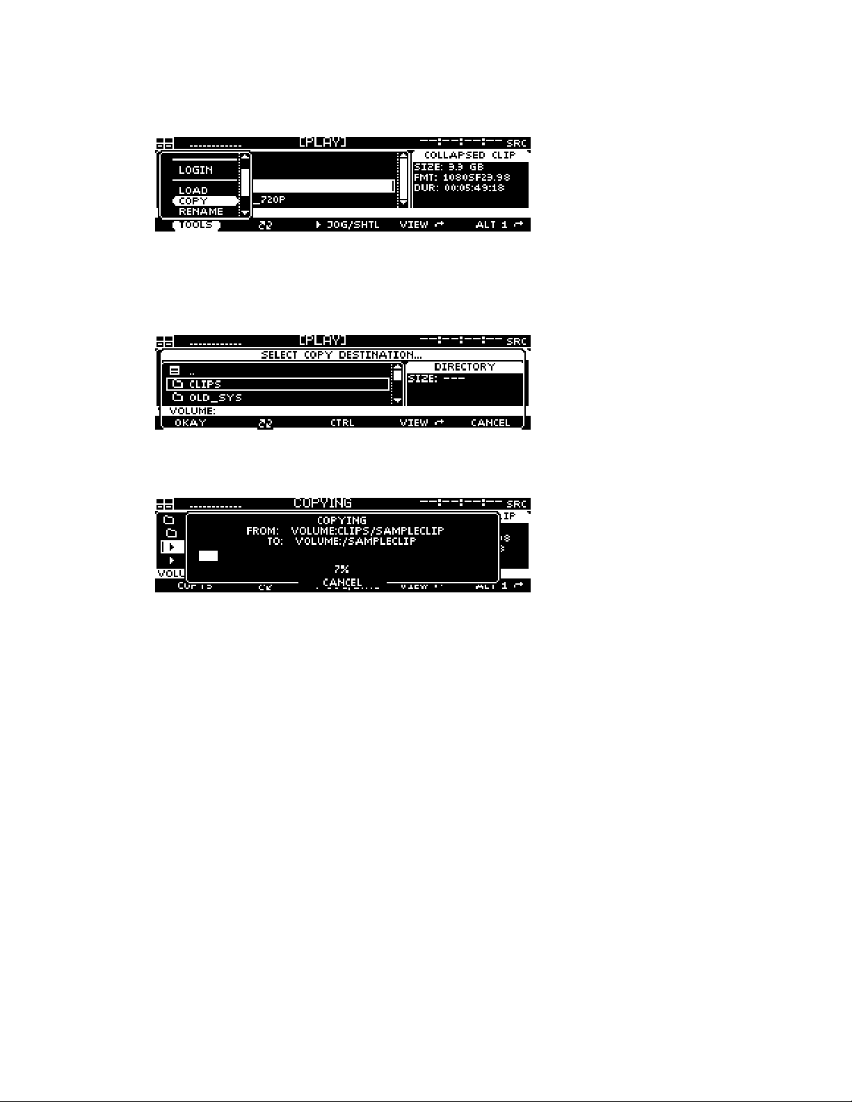
2. To copy the selected file(s), press the File button and select the Copy menu choice.
3. Select the destination by navigating to the new directory location using the file browser popup
window. The destination directory may be a directory on any of the locally mounted storage
volumes.
4. Press the Okay button to start the copy process.
Note: To cancel the operation, press the soft button labeled CANCEL (bottom center). If multiple files have
been selected to copy, canceling the current operation will stop all subsequent copy operations.
QuVIS Encore Page 46 QSR Version 3.1

CHAPTER 3 - PRODUCT DESCRIPTION
Information in this chapter includes:
Product Overview
•
Storage
•
QuVIS Media Files
•
User Security Features
•
Factors that Affect Picture Quality When Recording
•
Factors that Affect Picture Quality During Playback
•
Control Panel Overview
•
Introduction to the Graphical User Interface (GUI)
•
QuVIS Encore Page 47 QSR Version 3.1

Product Overview
The QuVIS Encore is multi-format single channel digital video recorder. The QuVIS Encore is uniquely
flexible as it capable of mastering and playing a wide variety of standard 4:2:2 video formats including
720p, 1080i, 1080sf, 1080p, NTSC and PAL at 24, 25, 30, 50 and 60 f/Fps.
Playable media is stored on hard drives, either internal or externally. As the QuVIS Encore does not
record, the content must be loaded onto the system via removable drive or network copy operation. The
QuVIS Encore can accept internal media drives from another system or from a QuVIS Acuity, QuVIS
Encore or QuVIS Encore. The QuVIS Encore can be used to assemble Computer Graphic Images, or
CGI frames, into a playable QuVIS media file using the QuClips image encoding application.
The QuVIS Encore connects to far more types of equipment than most video players, including a wide
variety of profession video equipment, computer systems and control mechanisms. With support for up
to 12 channels of digital audio and both analog and serial digital input and output options, the QuVIS
Encore is truly a multifunctional mastering and playback server.
The QuVIS Encore is controllable using standard serial remote control protocols including RS-232, RS422, Odetics and LDV8000. Editing with QuVIS Virtual Tapes (VTP) enables the QuVIS Encore to
emulate the editing process native to traditional VTR machines in a production environment. The
Encore may also be controlled over a network using software utilities provided by QuVIS such as QShell
and QuDAC or through a custom application using the robust QuVIS network API.
QuVIS Encore Page 48 QSR Version 3.1

Storage
The QuVIS Encore is configured with two LVD SCSI buses or channels, each capable of supporting up
to 14 devices including: internal SCA media drives, hot-swap removable hard drives and 8mm data tape
drives. Internal media drives are used to play video and audio in real-time. Removable hard drives may
also be used to archive content or to share content between similarly equipped QuVIS video servers.
Tape drives (Sony AIT) may be used to create an off-line archive of content for long-term storage or to
share content between units.
QuVIS internal hard drive media storage is configured to stripe data across multiple hard drives, with
each drive residing on its own SCSI channel, configured as a single storage volume. For storage and
bandwidth flexibility, QuVIS video servers support various drive volume widths. The number of drives in
a storage volume can vary, depending upon determined bandwidth requirements, from one to two
drives in a QuVIS Encore. A single-drive volume can be used to transport and share content between
QuVIS video servers or to play content that is data-rate limited, either by the video format, such as
NTSC or PAL, or by QuVIS data-rate controls. A single-drive volume will support a Maximum Data Rate
(MDR) of 30MB per second or MDR30.
Multi-drive volumes may be used to store and playback high data-rate content such as the 4:2:2 video
format 720p60. Multi-drive volumes may also be used to create very large storage volumes capable of
recording many hours of HD content on a single volume. The maximum data rate multi-drive volumes
can support on a QuVIS Encore is limited to 60MB per second or MDR60.
Drive order within a “non-boot” volume is not important, as volume order is determined during the
formatting process. Once a volume is formatted, the user may remove the volume and place the drives
back into the system or a different one in any order. The system will automatically identify which drive is
the proper logical drive in the stripe sequence. This auto-sequencing feature is very useful when using
hot-swap removable drives allowing the operator to concentrate on the process and not the sequence of
drives that make up a volume.
Placement of a “boot” volume, volume that contains the system operating software, is important. The
boot volume should always be placed in the bottom two positions of the Internal Media Bays. Removing
the boot volume from the system will render the unit inoperable from a video playback standpoint. If a
valid boot volume is not detected the unit will still power on but the operating system will have limited
functionality and playback will be disabled.
To ensure that drive failure does not interrupt a mission critical workflow the QuVIS Encore can be
attached to a highly reliable redundant external storage array, called a RAID array. RAID storage, or
Redundant Array of Inexpensive Disks, can be configured such that a single drive failure will not impede
the ability to play content. The QuVIS Encore can support multiple Terabytes of external storage by
attaching a RAID array to one or the two available external SCSI.
Volume Sizes
Internally, the size of a storage volume can vary depending upon the size of the drive and the number of
drives in the volume. Externally, a QuVIS Encore can support even larger volume sizes, up to multiple
TeraBytes (TB) of storage, using approved multi-channel drive arrays.
QuVIS Encore Page 49 QSR Version 3.1

Internal Media Bay Storage
The current video server products from QuVIS (QuVIS Cinema Player, QuVIS Ovation, QuVIS Encore
and QuVIS Acuity) offer new internal storage architecture designed to enable front panel access to
internal Media storage. This new architecture allows QuVIS Media storage to be shared between these
products by simply removing a volume from one machine and placing it in the Media bay of another.
The QuVIS Encore has four internal Media storage bays. Each Media bay accepts SCA (Single
Connector Adapter) SCSI hard drives that are mounted on removable drive sleds. Media drives are hotswappable meaning that they may be inserted or removed while the unit is powered on. SCSI device ID
assignment is handled automatically by the system depending upon which media bay slot the drive is
occupying. The following diagram lists the SCSI channel and device ID assigned to each Media bay.
Peripheral Bay
SCSI Channel 0x3
Media Bay 3
SCSI Device ID - 0x22
Media Bay 1
SCSI Device ID - 0x21
Note: The default location for the primary boot volume (volume that hosts the Operating System files) is Media Bay
1 and 2.
Installing/Removing Internal Media Drives
Media Bay 4
SCSI Device ID - 0x32
Media Bay 2
SCSI Device ID - 0x31
The QuVIS Encore internal media drives are mounted on removable drive carriers or drive sleds. Hard
drives mounted in the media bays are “hot-swappable” meaning that they may be inserted or removed
while the unit is powered on.
WARNING! Media drives should not be removed from the system while the machine is powered on.
Removing a drive sled from a media bay
Before you remove a hard drive sled from a media bay, please ensure that the system is not currently
performing a read or write operation (copy, delete, play, tape backup, etc.). Use the following procedure
to remove a media drive.
1. Lift up the front control panel to expose the media bays.
2. To remove the drive sled, place your fingers in the left and right finger holes and pinch the tabs
towards the center of the sled. While the tabs are held towards the center of the sled, firmly pull
the sled toward you in a straight motion.
Inserting a drive sled into a media bay
Use the following procedure to insert a SCA (Single Connector Adapter) hard drive sled into a media
bay.
1. Drive sleds inserted into a QuVIS Encore media bay must be placed in the horizontal position.
Follow the positioning instructions on the drive sled for proper horizontal orientation.
2. Line up alignment tabs on the sides of the drive sled with the alignment channel inside the
media bay. Slide the drive sled into the media bay. A small push with your finger may be
needed to secure the drive sled into position.
QuVIS Encore Page 50 QSR Version 3.1

Peripheral Bay Storage
The QuVIS Encore accepts a single 5 ¼” SCSI device in the optional internal Peripheral Bay. The
Peripheral Bay may be configured with a half-height (5 ¼”) removable drive assembly for transporting
content between QuVIS video servers. Alternately, the Peripheral Bay may be populated with an 8mm
Sony AIT tape drive for transport and archiving applications. The Peripheral Bay takes on the SCSI ID of
the device that is installed in that slot.
Removable hard drive media allows the server to store all supported video formats to the same media
without requiring separate virtual or physical partitions of the drives for different clip/video formats. With
scaleable storage options, several hours of superior quality high definition video can be shared between
servers in just a matter of minutes. With “hot-swap” removable drive support the dismounting and
mounting of removable drive volumes can be done live with the system powered on.
Archiving Data
Using native software tools, data and media files can be archived to or loaded from high-capacity 8mm
tape backup devices such as the Sony AIT-2/3 tape drive. A single AIT-3 tape cartridge can store up to
100GB of data or in QuVIS terms, in excess of 2 hours of HD-1080 playable media. Once data has
been backed up to this archive magnetic tape media, the content can be safely stored for long-term
archiving or immediate off-line retrieval.
QuVIS Encore Page 51 QSR Version 3.1

QuVIS Media Files
Files that contain video and audio data are commonly referred to as clips or media files. There are
several types of media files that can be created and played by QuVIS video servers. Determining the
type of media file to use is very important. Each media file type is constructed differently in order to
efficiently achieve the intended use of the content (video and/or audio).
Aside from the video and audio format of the media file, there are three settings that serve as the
foundation of a media file. These settings are: QuVIS Media Format (QMF), Maximum Data Rate (MDR)
and Clip Form.
QuVIS Media Format (QMF)
The QuVIS Media Format is a compatibility switch that identifies different file format standards used by
QuVIS video servers. There are currently two compatibility modes: QMF1 and QMF2.
– This QMF setting is used to identify collapsed clips (interleaved video and audio) that
QMF1
may be played by the first generation QuVIS video servers, the QuBit, running a QuVIS Soft
Release (QSR) of 1.x.
IMPORTANT! The QuVIS Acuity, QuVIS Encore, QuVIS Ovation, and QuVIS Cinema Player do
support the playback or creation of QMF1 content. QMF1 content may only be played and
NOT
created by previous generation QuVIS products running QSR 1.x or 2.x releases including the
QuBit ST, DS and EL. This legacy clip file format has built-in controls that limit the options
available for MDR, Metadata and Clip Form in order to maintain playback compatibility with
older 1.x QuBits.
QMF1 clip settings
• MDR = Maximum of 30MB/sec
• Metadata = Not supported
• Clip Form = Collapsed only (interleaved video and audio)
QMF2 (default)
created or played on QuVIS video servers running a QSR release of 2.x or greater, including
QSR 3.x. The QuVIS Cinema Player, Ovation, Encore, Acuity and QuBit product line (ST, EL
and DS) natively supports this QMF setting. QMF2 supports features that are tied to specific
levels of hardware (circuit cards) that are not available for 1.x QuBits.
QMF2 clip settings
• MDR = 30 and 60MB/sec supported
• Metadata = supported
• Clip Form = Collapsed and expanded
Maximum Data Rate (MDR)
MDR is used to set the upper data rate limit of a media file to 30 or 60 MB/sec. These limits are set to
correspond to the bandwidth capabilities of the QuVIS video server that is recording the content or
intended to play the content. A 1.x QuBit for instance can only support a maximum date rate of
30MB/sec. Current products running QSR 2.x or greater support a maximum data rate of 60MB/sec.
Aside from the product model and system software version, another important element that determines
the ability to record or play MDR 60 content is the number of drives that make up a QuVIS storage
volume. A single-drive volume can only support a maximum data rate of 30MB/sec. Multi-drive volumes
(2 or more drives) will support MDR 60 and is capable of sustaining data rates of 60MB/sec.
– This default QMF setting is used to identify media files that may only be
QuVIS Encore Page 52 QSR Version 3.1

Clip Form
There are two primary clip form types: collapsed and expanded. The form of the media file dictates how
the video and audio assets of a media file are physically stored on disk. The other important element
that is dictated by clip form is whether or not the media file can be used in an editing environment.
Collapsed
together in a single file. Collapsed media files are typically used to distribute a completed
project as a single playable media object.
Expanded
Expanded media files that belong together share a common base name but have different file
extensions to indicate the stored asset, video (.v) or audio (.a).
Expanded audio assets have additional flexibility that allows QuVIS video servers to store audio
assets as either a collection of all audio channels (cluster) or as individual audio tracks (discrete
channels) stored in separate files. An “audio cluster” is designated with a “.a” file extension.
“Audio tracks”, stored in separate files, are designated by a “.ann” file extension where “nn”
indicates the audio channel number the file was recorded on. For example, the file that contains
audio recorded on channel 1 would have the file extension “.a01”.
Expanded media files are structured to enable real-time editing using a QuVIS Virtual Tape
editing object. Virtual Tapes enable QuVIS video servers to emulate a traditional linear tape
editing process while provide the additional flexibility of a digital workflow.
– Media files that are “collapsed” have both audio and video assets interleaved
– Media files that are “expanded” use separate files to store video and audio assets.
Virtual Tapes
A QuVIS Virtual Tape (or VTP) emulates a traditional pre-striped videotape (a pre-formatted tape
containing video black and timecode) for editing in a post-production environment. Virtual tapes are an
editable media object that may only be created and edited by a QuVIS mastering server (QuVIS Acuity,
QuVIS Encore and QuBit ST). The QuBit DS may only be used to create a new VTP and “crash-record”
into a Virtual Tape. All current QuVIS video servers (QSR 2.3 or greater) can be used to play Virtual
Tapes. Offline clip tools, such as the Modclip command, may be used to create other playable media
files (including collapsed clips) using a VTP file (or timeline file) as the source.
Virtual tapes lets you record and edit content directly on the QuVIS mastering server as though it
contains a fixed-length, striped videotape. Unlike traditional linear tapes, the recorded edits or media
assets of a VTP are stored in their entirety as clip files and the edit points are managed independently in
the VTP container file.
Editing a VTP is a non-destructive process, meaning that when an edit is performed a new asset or clip
is created and does not overwrite existing data. Instead of overwriting any data on the VTP, a new set of
pointers within the VTP container file are created to point to the location of the new content.
A Virtual Tape consists of several elements:
Virtual Tape Media File
properties that defines how the VTP was formatted. These properties include: video format,
tape length, audio properties (bit-depth and resolution), timecode and metadata. Additionally,
this file maintains the list of video and audio edits that have been performed.
Virtual Tape directory
same parent directory, is used to store all of the physical video and audio edits (clips) that have
been recorded. The media file types that make up the individual edits are expanded clips.
– This media file, designated with a “.vtp” file extension, maintains the
– A VTP directory having the same name as the .vtp file, located in the
QuVIS Encore Page 53 QSR Version 3.1

Virtual Tape Timeline
file is a compiled version of the .vtp file that allows the system to edit or play the Virtual Tape in
real-time. The timeline file is automatically generated or updated by the system each time an
edit is performed. This file may not be copied or backed up. If the auto.tl file does not exist, the
system will automatically regenerate this file when the virtual tape is played or edited.
QScript Files
A QScript or script file is a special file that instructs the system how to play various segments of media
files without interruption as if they were one seamless production. Script files are more than just a list of
clips that are to be played in sequence. Widely used as a Digital Cinema playlist, script files are capable
of specifying specific in and outpoints to be played as well as issue system commands to control
external devices such as theater light-management and digital projector settings.
A script file can be played like all other media files from the front panel GUI. Unlike standard media files
(clips and virtual tapes) a script file can be manually edited using a text editor or the Show Builder menu
utility. For more information on creating script files from the GUI, see section PLAY – Show Builder
menu page.
IMPORTANT! Script files may not be placed under remote serial control for editing or playback.
– A special timeline file, auto.tl, is stored in the Virtual Tape directory. This
QuVIS Encore Page 54 QSR Version 3.1

System Security Features
The QuVIS Encore includes system security features that allow the server to be configured with user
accounts and permission levels. Security information is stored in an encrypted format and stored in
manner that prevents tampering and unauthorized access to user account information.
By default, the Encore ships with its security features disabled, which allows the user to customize the
system freely. However, you may wish to enable “user privileges” that are assigned to known operators
(users). These privileges or security levels are used to restrict access to sensitive operations or
commands based upon the users account type.
If security is enabled, the unit will power on without requiring a user login but will only support “User”
level operations. This allows the system to be ready to play content immediately without requiring user
login intervention.
Security Levels
Currently there are three security levels (user, technician, administrator), each allowing the operator a
different degree of operator freedom. Security levels are enforced from all system interfaces (QShell,
Telnet, FTP and GUI).
If system security is not enabled, default access is set to Administrator level permissions.
USER
This is the power-on default and lowest user level. This user level is essentially limited to being able to
only play content. Logging out of another level leaves one in the User level. The system log is viewable
by users in order to be able to report system warnings or errors.
The Play Browser starts in the SCRIPTS directory for User level access.
Supported Operations
Browse and select Show Scripts (playlists) (PLAY – Browser menu page) •
•
Play content, including starting, stopping and pausing play out (PLAY – Control menu page)
•
Issue a predetermined GPI (automation) signal to start, pause, or stop playback.
•
View system log
TECH
This security level is for advanced users who are entrusted with content management functions
including the recording or loading of new content, removing old content and show script (playlist)
management.
Supported Operations
•
All User functions
•
Record content
•
Content Management
•
Playlist (show script) Management
QuVIS Encore Page 55 QSR Version 3.1

ADMIN
This highest level of access or security provides access to all system functions and menus allowing an
Administrator to completely manage all aspects of the systems setup including user security.
Supported Operations
All Technician functions •
• • System setup and configuration management
Security management
Account Management
Account management is currently available via the ACCOUNT QShell (command line) utility. The
ACCOUNT command may be used to LIST users, ADD new accounts, DELETE existing accounts,
ENABLE account, DISABLE account, IMPORT accounts from an existing “users” file, and turn ON|OFF
the security system. For usage details for the Account command, refer to the “QShell Command
Reference Manual”.
QuVIS Encore Page 56 QSR Version 3.1

Factors that Affect Picture Quality When Recording
QuVIS video servers, including the QuVIS Encore, have several settings that affect picture quality in
different ways. These can be categorized into two broad groups: those that affect picture quality
directly (such as the SNR control) and those that limit the picture quality possible (controls related
to data rate management, which may in turn limit picture quality).
Following are the items that affect recorded picture quality.
External Factors
Source Material
Image quality cannot be improved beyond that of the source material. The motion content, clarity and
grain of the source material will have some affect on the data rate of the recorded footage.
Signal Chain
Image processing components (noise/grain reducers, video distribution amplifiers, etc.) in the signal
chain itself can degrade picture quality.
Internal Factors
1.
Image Quality (RECORD – Media menu page)
This control has the greatest direct affect on picture quality.
Note: Using a high SNR with a low MDR can force a situation where the failsafe is turning on too often. It’s
best to match the SNR setting to the source material, or set it only slightly above the SNR of the source
material, to avoid the data rate reaching the MDR setting.
2. Maximum Data Rate (RECORD – Media menu page)
MDR can have a moderate to more extreme effect on picture quality, based on whether it is set
correctly or incorrectly for the source material and SNR. Set correctly, it will monitor and gently
soften image quality only as needed for extreme peaks in the data rate. If set incorrectly this setting
can cause the system to constantly turn on the data rate failsafe which can artificially lower image
quality.
Note: The data rate failsafe mechanism lowers image quality when the data rate exceeds the MDR setting.
Using a high SNR and a low MDR can force a situation where the failsafe is turning on too often. It’s best to
match the SNR setting to the source material, or set it only slightly above the SNR of the source material.
3. QuVIS Media Format (RECORD – Media menu page)
QMF selects between legacy-format clips and new clip formats with data rate cap options: MDR30
and MDR60.
4. Destination volume capacity (RECORD – Input menu page)
The destination volume may contain one or two hard disk drives. A one-disk volume cannot receive
data as fast as a volume with two or more drives. Recording 60p or dual-link HD-SDI content to a
single-drive volume is not recommended as the system may find it necessary to soften the picture
quality if the peak data rate exceeds the performance capabilities of the single hard drive.
QuVIS Encore Page 57 QSR Version 3.1

Factors that Affect Picture Quality During Playback
QuVIS Encore Output Settings
QuVIS video servers, including the QuVIS Encore, have several settings that affect the playback picture
quality in different ways. You will want to know about these to ensure the system is always set up for the
highest quality output. Following are the software-controllable items that affect playback picture quality.
1. Bit Depth Compatibility (OUTPUT – Video menu page)
When playing content from a QuVIS Encore and recording it on another VTR, you may need to use
the Bit Depth setting to match the bit depth of the output signal more closely to that of the capability
of the destination VTR. When output is not rounded down in this manner, the receiving VTR’s
circuitry may be unable to handle the excess data and produce lower-quality recorded images as a
result. Our recommendations for dubbing among common equipment are below.
Format QuVIS Encore Bit Depth
Output
HDCam 8 bit
D-5 9 bit
HDCam SRW 10 bit
10 bit SMPTE
compliant
Uncompressed HD 10-bit
2. Dither (OUTPUT – Video menu page)
When turned ON, Dither inserts electronically-generated noise into the picture. This may be useful
for some displays where it may produce a sharper-looking image. It is not recommended for
production work or output to plasma monitors, projectors or VTR’s (the added noise can be
misinterpreted by their circuitry and cause a degraded image). By default, Dither is turned off.
3. Analog Colorspace (OUTPUT – Analog menu page)
This control adjusts the output colorspace for your display device. If you connected the QuVIS
Encore to a monitor, projector or VTR with a confidence monitor, and the video is excessively green
or magenta-tinted, the wrong colorspace may be being used. Use this control to change the video
output colorspace on the QuVIS Encore.
4. Genlock (OUTPUT – Video menu page)
When the QuVIS Encore plays back content, it can “reference” its video output signal either to a
master timing source or its own internal clock. The internal clock is commonly used in situations
where the QuVIS Encore is simply playing back content for a trade show, digital cinema, or
boardroom presentation, and the display device is the only other equipment connected to the QuVIS
Encore.
10-bit
QuVIS Encore Page 58 QSR Version 3.1

Factors External to QuVIS Encore
1.
Display device signal processing values
Due to differences in digital signal handling, display devices vary in their ability to reproduce a
usable picture. Digital projectors tend to display every flaw in a video signal. The same video signal
that looks wonderful on your office CRT monitor may be terrible on a digital projector. High-end
projectors show the signal with much greater accuracy than most monitors do.
However, even the digital circuitry in a brand name projector is not always above suspicion. The
digital signal path through the projector can degrade the image, and the change in quality may
range from unnoticeable to unusable. This varies not only from one brand to another, but also from
one product line to another in the same brand (sometimes engineering teams work as discrete
entities when designing product).
If you are having unexpected picture quality issues, first verify that you are viewing the material in
the same manner (i.e., on the same make and model) that you previously used. If it is different,
expect some quality differences. After that, the best solution is to check the settings for the display
devices, and check the other inputs to see if a better quality picture can be obtained by running a
signal into it via a different input (i.e., using HD via component RGB rather than SDI).
2. Cable quality and cable length
The quality of your cable makes a big difference. Cables of the same length but from different
manufactures will exhibit different performance characteristics. Where possible, QuVIS
recommends you use Belden 1694A “Brilliance” or equivalent cable for serial digital video
applications.
Remember that even quality cabling is subject to principles of physics (attenuation of the carrier
signal due to distance, connections, and patching equipment). For all cables, long cable runs will
weaken high-frequency signals, and unshielded electrical sources (like power cables placed
alongside video cable) can definitely interfere with the signal.
Video output signals can travel anywhere from 25 feet (7.6m) to 335 feet (102m) depending on the
quality rating of the cable used. If you need a longer run than your cable supports, you will need to
use the proper distribution amplifier to boost/equalize the signal.
3. Ambient light and screen framing
The amount of ambient light in a room has a direct bearing on the depth and clarity of the images
you see. This is the reason movie theatres are nearly black inside. The more you can control the
light levels in the room, the better the image.
In addition, many projection screens are framed with a wide black frame. This enhances the
appearance of brightness and clarity to the eye.
QuVIS Encore Page 59 QSR Version 3.1

Control Panel Overview
The QuVIS Encore Control Panel provides the visual display and physical controls required for local
operation. The Control Panel consists of three (3) main elements:
Status LED’s
•
• Menu Display
• Navigation and Selection Buttons
• Jog/Shuttle Wheel
• Soft Buttons
Raising the Control Panel exposes the peripheral bay (if populated), the internal media bays, the power
button, and auxiliary connections (headphone, RS-232 Port A and PS2 keyboard connector).
Status LED’s
Menu Display Jog/Shuttle Wheel
Status LED’s
General system status information is available from the front panel through the use of Light Emitting
Diodes (LED’s). Each of the four front panel LED’s are assigned to monitor specific system events.
Network – When lit, this LED indicates that a network connection has been opened with the QuVIS
Encore. This includes any of the following network services: Telnet, FTP, HTTP, and the network API.
HDD – This LED is used to show hard drive activity. Both read and write drive operations are indicated
on this LED.
Remote – This LED will illuminate when the system is placed under remote serial control.
Log – This LED will illuminate when new unread system events have been added to the system log.
This indicator has two states or colors to indicate the type of event added to the log.
Yellow – used to indicate that an unread system message or warning is stored in the log.
Warnings do not indicate a problem has occurred but rather that the potential for a problem has
been reported.
Soft Buttons
Navigation and
Selection buttons
QuVIS Encore Page 60 QSR Version 3.1

Red
– used to indicate the occurrence of a critical system message. This type of message
means that a system failure has occurred. If the LED is illuminated red, the system log should
be immediately read to determine if corrective action is needed.
Menu Display
The VFD (Vacuum Fluorescent Display) screen is used to display the Graphical User Interface or GUI
used for local operational control of the QuVIS Encore. The GUI is a collection of menu screen (pages),
status indicators and controls that provide access to the system settings and operational control over all
front panel operations.
Navigation and Selection Buttons
The buttons to the right of the user interface display are fixed function buttons that provide the key
functions needed for menu navigation, list navigation and item selection. The primary function of each
button is labeled to the left of each button.
Navigation and
Selection Buttons
CANCEL (red)
(UP)
(DOWN)
SELECT (green)
MENU (blue)
Description
This button is used to back out of an operation or close a popup window
without applying any changes that have been made but not saved.
This button is used to move the selection focus object up a list of items
and in certain instances change the value of a control in the positive
direction.
To scroll through a list of options or quickly advance a value, press and
hold this button.
This button is used to move the selection focus object down a list of
items and in certain instances change the value a control in the negative
direction.
To scroll through a list of options or quickly advance a value, press and
hold this button.
This button is used to select the item that has current focus such as
selecting a script file in the file browser for playback. In some instances
it is also used as an Enter function, meaning that pressing this button
will cause an action to be performed such as accepting a new value
from a popup window.
This button is used to open the list of available menu pages. This button
works under most circumstances but may not be available under special
conditions such as when a popup window like the file browser is loaded.
To reduce the number of button presses it may take to navigate through
the complete list of menu pages, navigational shortcuts using this menu
button are available. This shortcut method allows you to jump between
menu groups and individual pages very quickly. To activate the shortcut
menu list, press and hold the blue menu button. The “soft” buttons of the
GUI are temporarily reassigned (while the Menu button is held) as menu
QuVIS Encore Page 61 QSR Version 3.1

Navigation and
Selection Buttons
Description
page shortcuts.
The two outer buttons with the arrows next to the button label are used
to jump to the listed menu group. In the example above, if you press the
soft button labeled “<< Setup”, the SETUP menu group would be
displayed.
The two inner buttons (with ∧ and ∨ arrows) are used to navigate
between the menu pages of the current menu group (in this case the
PLAY menu group).
QuVIS Encore Page 62 QSR Version 3.1

Jog/Shuttle Wheel
The Jog/Shuttle wheel is comprised of two separate controls that are controlled independent of each
other. The outer Shuttle ring is used for variable speed playback control. The inner Jog wheel is used
for frame-by-frame playback control. The GUI Dashboard will display the active function as well as the
speed and direction of playback.
The Jog/Shuttle wheel is only active if the active playstyle is “Play Jog/Shuttle”.
The shuttle ring has a visible and physical center position indent or market to identify the pause or zero
speed playback position.
Jogging a clip
To frame advance or JOG through a clip, use your finger to rotate the inner wheel in the desired
direction (left = reverse, right=forward).
Shuttling a clip
To shuttle through a clip turn the outer ring in the desired direction from the center indent or position
marker (left = reverse, right = forward). As the shuttle ring is turned the speed of playback will increase
in the direction indicated. If the shuttle ring is turned back towards the center indent the speed of
playback will decrease.
Soft Buttons
The buttons along the bottom of the display are soft buttons, meaning that their function assignment is
changed in software depending upon the active menu page. The assigned function of each button is
shown directly above each button on the user interface.
QuVIS Encore Page 63 QSR Version 3.1

Introduction to the Graphical User Interface (GUI)
Local control of the QuVIS Encore is performed from the front panel using the Graphical User Interface
or GUI. The GUI menu system is a collection of menu pages that provides a single interface to perform
the basic operations needed to play content, manage files, monitor status and change the configuration
of the unit.
The GUI is automatically started once the unit has completed its power on cycle. Once the GUI is
loaded on the front panel display, all system services are available including local and remote control.
This section provides a description of the GUI menu system.
• Overview
• Menu Navigation
• Dashboard
• Menu Page Controls
Overview
The front panel menu system features fast access to any of its dozen-plus screens or menu pages.
Menu pages are collated into logical groups in order to place pages with similar control in close
proximity of each other.
DASHBOARD
PLAY
PG 1/3
PLAY
PG 2/3
PLAY
PG 3/3
DASHBOARD
OUTPUT
PG 1/5
PLAY
PG 2/5
PLAY
PG 3/5
PLAY
PG 4/5
PLAY
PG 5/5
DASHBOARD
REMOTE
PG 1/2
PLAY
PG 2/2
DASHBOARD
SETUP
SETUP
PG 1/5
SETUP
PG 2/5
SETUP
PG 3/5
SETUP
PG 4/5
PG 5/5
The primary setup and configuration menu pages (Record, Output, Remote and Setup) are labeled
making it easy to quickly identify what menu group and page is currently active. Fast navigation
between menu pages is achieved using the soft buttons (below the display) to advance to the next page
within the group in either direction. Group navigation is achieved using the popup window activated by
pressing the MENU button.
The PLAY group of menu pages is the exception as these are the menu pages that will most often be
accessed and therefore are governed by a different rule set.
IMPORTANT! The exact number of menu groups and pages may change. The example given above is
only an illustration of the menu navigation and layout concept. The actual number of screens will vary.
QuVIS Encore Page 64 QSR Version 3.1

Menu Navigation
The MENU button is provided to enable navigation to any menu page from a single control. Pressing the
MENU button activates a popup window that lists all of the available menu pages. A white triangle to the
left of the menu page name is used to indicate which menu page is currently loaded.
Selecting a new menu page
1. Press the MENU button to activate the list of available menu pages.
2. Use the or buttons to browse the list of available menu pages.
3. Press the SELECT button to load the selected menu page.
Note: There are instances in which pressing the MENU button will not activate the menu list. This behavior
will occur if there is currently a popup window active awaiting feedback from the operator. Please close
any open window before pressing the MENU button.
Menu Navigation Shortcuts
To reduce the number of button presses it may take to navigate through the complete list of
menu pages, navigational shortcuts using this menu button are available. This shortcut method
allows you to jump between menu groups and individual pages very quickly. To activate the
shortcut menu list, press and hold the blue menu button. The “soft” buttons of the GUI are
temporarily reassigned (while the Menu button is held) as menu page shortcuts.
Menu group navigation
The two outer buttons with the arrows next to the button label are used to jump to the listed
menu group. In the example above, if you press the soft button labeled “<< Setup”, the SETUP
menu group would be displayed and the button would be reassigned to indicate the next menu
group available in that direction.
Menu page navigation
The two inner buttons (with
the current menu group (in this case the PLAY menu group).
∧ and ∨ arrows) are used to navigate between the menu pages of
QuVIS Encore Page 65 QSR Version 3.1

Dashboard
The most important element of the front panel GUI is the dashboard, a strip of indicators at the top of
the display that provide instant feedback about the current status of the Encore.
Dashboard Display Views
There are two dashboard views (large and small) that are displayed depending upon what menu page is
currently active. The dashboard areas in both views are protected display areas meaning that any
popup windows or input control will not impede the information being displayed within the dashboard.
Large Dashboard View
The large dashboard view is used on primary menu pages such as the PLAY – Control menu
page. This large view shows all of the components of the dashboard in a large state for easy
readability by the operator.
Small Dashboard View
The small dashboard view used on secondary menu group and pages (all setup menu pages) in
order to provide enough room on the display to allow the operator to make changes to the
configuration of the unit and still monitor the status of the machine.
Dashboard Indicators
From left to right the dashboard indicators are as follows:
1) Internal Hard Drive Indicators
a. Each drive box maps to the drive slot that is found under the front panel
b. Solid Box indicates a mounted drive
c. Dash indicates a drive occupies the slot but is not currently mounted
d. Empty Box indicates that no hard drive is detected in the Internal Drive Slot
2) Audio Meters
3) Transport Status
4) Timecode Indicator
Internal Hard Drive Indicators
The internal drive indicators are used to indicate the presence and mounted status hard drives in
each of the internal media bay slots. Hard drive activity (read/write) is indicated on a LED light
located to the left of the display. Each dashboard drive indicator box is mapped to the appropriate
slot as according to its relative position. The top-left indicator is mapped to the top-left internal drive
slot. The top-right indicator is mapped to the top-right drive slot.
QuVIS Encore Page 66 QSR Version 3.1

Hard Drive Indicator States
There are three states of presence for internal hard drives.
Not Present / Not Detected (Box is empty) – This states indicates that no hard drive has been
detected in that drive slot.
Drive Detected / Drive Not Mounted (White Dash) – This state indicates that a drive is present
in the drive slot but that the drive is not currently mounted. This status indicator is a visual cue to the
operator that the drive may be removed from the system safely.
Drive Detected / Drive Mounted (White Box) – This state indicates that a drive is present in
that drive slot and that the drive is currently part of a mounted volume. This status indicator is a
visual cue to the operator that the drive may NOT safely be removed from the system.
Audio Meters
The dashboard audio meters will only show activity on each of the available channels. All 12
available channels are represented even when there is not activity on that channel.
Transport Status
The center area of the dashboard is used to display current Transport and System status states.
Special “states” or modes will be shown in brackets as described below.
New transport/system states may be added in order to support content loading operations.
[PLAY] Encore is in a “play” state, but not yet playing clips (i.e., vmode p).
[RECORD] Encore is in a “record” ready state, but not yet recording (i.e., vmode r).
[READY] Encore is in neither a “play” nor “record” state (i.e., vmode n).
This may appear when performing diagnostics, for example.
BUSY Encore is busy switching modes, and is not ready for GUI control.
RECEIVING Encore is receiving content from a unit via Ethernet.
RECORDING System is currently recording content.
PLAYING Encore is playing content (at 1X speed).
LOOPING Encore is looping content (at 1X speed).
ARMED-SYS Encore is paused in Play mode awaiting a system time play trigger.
ARMED-TC Encore is paused in Play mode awaiting a time code play trigger.
SENDING Encore is sending content to another unit via Ethernet.
SHTL-PAUSED Encore is paused in Shuttle mode (Play).
SHTL +nX Encore is scanning Fwd (+) at “n” speed (n is a decimal).
SHTL -nX Encore is scanning Rev (-) at “n” speed (n is a decimal).
JOG Encore is Jog mode and virtual J/S wheel is active.
COPYING Encore is currently performing a copy operation.
BACKUP Encore is copying selected files to tape (reading from hard disk drives).
RESTORE Encore is restoring archived files from tape (writing to hard disk drives).
FORMAT Encore is formatting a tape.
QuVIS Encore Page 67 QSR Version 3.1

Timecode Indicator
The timecode indicator displays the appropriate timecode value as content is being played or
controlled. The primary (upper white) timecode indicator will follow Encore timecode controls and
operation.
The primary TC indicator will default to TCV when either a virtual tape or timeline with virtual
timecode is selected for playback.
The primary TC indicator will follow the LTC output (OUTPUT – Timecode menu page) control
setting when in play mode and the Timecode Source control (RECORD – Input menu page) while
recording. If a clip to be played back has source time code AND the LTC out control is set to
“Original Source LTC”, then SRC timecode will be displayed; otherwise ABS timecode will be
displayed.
QuVIS Encore Page 68 QSR Version 3.1

Menu Page Controls
Menu pages generally use the same type of button object to indicate what option or function has current
focus. There are a couple of menu pages (PLAY – Control, PLAY – Browser and PLAY – Show
Builder) that are not laid out in the same manner as the majority menu pages. These menu pages are
considered specialty pages and are governed by their own set of “specialty rules” and may use
selection objects not found on other pages.
Selection Control Types
Button Controls
Button objects are used to visually show the operator what menu page option has “selection focus”. The
button look is used to let the operator know that they must press a button in order to edit the displayed
value or view the information the control contains.
There are two button controls, full width and half width. Buttons are used to activate a popup window to
display information or change the assigned value on an Environment Variable (EV). Half-width buttons
are used to separate two menu options on the same line.
List Navigation Bar Control
The list navigation bar control is used on display objects (file browser, menu selection window and item
lists in popup controls) that present a list of selectable items. The “scroll bar” dynamically changes size
depending upon the number of items in the displayed list. The smaller the scroll bar (between the two
arrows) the longer the list. The scroll bar moves up and down between the two arrows to indicate
relative position within the list.
File Browser Asset Identifiers/Icons
Volumes, directories and file names in the file browser control (including the PLAY – Browser menu
page) are preceded by an icon that visually associates that item with its intended data type and usage.
The icons are shown below in their non-selected and selected (highlighted) states and are sorted into:
drive structure, file identifier, and playable asset groups.
Playable Asset
Timeline file (.tl)
Virtual Tape (.vtp)
Collapsed clip (video and/or 1-12 audio tracks)
Expanded clip, video (only)
Drive
Structure
Directory Executable Expanded clip, collapsed audio (2-12 audio tracks)
Volume File Script files
File
Identifier
Expanded clip, expanded audio (single audio tracks)
QuVIS Encore Page 69 QSR Version 3.1

List Item Navigation and Selection
There are several menu objects that present a list of items or options. With the exception of file browser
controls, all list objects follow the same basic rules for navigation and selection.
1. Selection focus is indicated surrounding the list item with either a white box or button.
a. Buttons are used to indicate that by pressing the SELECT button the action is complete or
the value must be changed. In the below example, if you press the SELECT button the
PLAY – Browser menu page will load.
b. The selection box is used to indicate that the item surrounded by the box may be selected
for a specified operation. In the example below, the selection box is used to indicate
backspace functionality during a rename operation. The selection box may be moved to any
character in order to rename the filename. To perform the function outlined by the selection
box (add character, remove character, etc.) all one needs to do is to press the green
SELECT button.
2. A small right arrow to the left of a list item indicates the currently assigned or active item. Popup
controls that display a list of available operations, such as the FILE menu popup on the PLAY –
Browser menu page, do not use the “assigned value” indicator as the list does not contain a
saved value but rather a list of system operations that may be performed.
Navigate or Scroll a List of Items
The
scroll through a list of items, press and hold the
Item Selection (Button objects)
When button objects are used to show focus within a list of options, pressing the SELECT button will
accept the item and complete the selection operation.
QuVIS Encore Page 70 QSR Version 3.1
and buttons (located to the right of the display) are used to navigate a list of items. To
or button until the desired value is selected.

Selection Box Properties
The visible state of the white selection box changes depending upon state of the file that is currently
showing as being in focus. The file that is currently in focus (surrounded by the white selection box) is
either selected or not selected. The state of the file in focus in important as it changes the appearance
of the “selection box” so the operator is able to easily tell what file or list item has current focus. If a file
has been selected, the area around it and its text are inverted to show selection.
File Selection States
1. Single file in focus but not selected.
2. Single file selected and in focus.
3. Multiple files selected, first file selected in focus.
File Browser Directory Navigation
In order to navigate the directory structure of a storage volume, select the directory you wish to open
and press the SELECT button. To navigate to a parent directory or back up the directory tree (toward
the root directory) select the parent directory icon (
SELECT button.
) listed on top of the file list and press the
If the file browser is at the root or lowest directory position of the current storage volume, the parent
directory icon will change to the volume icon (
QuVIS Encore Page 71 QSR Version 3.1
) to indicate that by volume list can be accessed by

pressing the SELECT while the volume icon is highlighted To navigate to the parent directory, place the
selection box on the parent directory line and press the SELECT button (see picture below).
TIP: List wrap-around is a supported feature in the file browser controls. If you are at the top of
file list and wish to quickly navigate to the end of the list, simply press the
to the end of the list. List wrap works the same in the other direction as well.
Update the File Browser File List
The “refresh” soft button is used to update the listing of files within the file browser window without
having to exit and return to the directory. This is useful is a file has been added by remote means such
as FTP.
Refresh button
Edit Value and Toggle Buttons
and you will wrap
Some menu-page options do not open a separate dialog window or popup but rather allow the value to
changed using the
Range Buttons
Some menu options like “Master Volume” have a large range of values that it may be set to (0 – 100%).
To list all of the possible choices in a Popup list control would be very difficult to manage and impractical
to navigate. For this reason the button control changes states once the SELECT button has been
pressed. This gives focus to the value portion of the menu option enabling the operator to change the
value using the
Stage 1: Menu option has focus but has not been selected to edit.
Stage 2: Menu option has been selected and the value may be changed using the
buttons.
QuVIS Encore Page 72 QSR Version 3.1
, and SELECT buttons.
or buttons.
and

If the menu option contains a large range of possible values, the behavior of the
will change depending upon the how the button is pressed:
1. Pressing and releasing the or button causes the value to increment or decrement by 1.
2. Pressing and holding the or button will continue increment or decrement the value by 1
(increasing in speed) until the button is released.
Toggle Buttons
Some menu options only have 2 choices, such as ON or OFF. In this case the menu button works the
same as the Range Button but only provides two choices. There is one difference however, which is
that the list cycles so that if you press the
Popup Windows and Dialog Boxes
Popup windows and dialog or input boxes are used extensively throughout the GUI.
Popup Windows
These are used to present lists of available values or actions. In most cases, pressing the SELECT
button will close the popup window but may open a dialog box depending upon what action was
selected.
and buttons
or button twice, it cycles back to the starting value.
Dialog Boxes
Dialog boxes are used to prompt the user for additional input, such as specifying the location for copy
operation, or to display information on the screen relevant to the last action initiated. The soft buttons
below the display are used to complete the operation and close the dialog box. In some instances, the
dialog box will close automatically once the selected operation has completed. For example, the dialog
box that displays the progress of a copy operation will automatically close when operation has
completed.
TIP: Pressing the red CANCEL button will close the open dialog box without any action being
taken.
QuVIS Encore Page 73 QSR Version 3.1

CHAPTER 4 - FRONT PANEL GUI INTERFACE
Information in this chapter includes details of the front panel menu system including menu groups, menu
pages and system controls.
PLAY menu group
•
RECORD menu group
•
EDIT menu group
•
OUTPUT menu group
•
REMOTE menu group
•
SETUP menu group
•
QuVIS Encore Page 74 QSR Version 3.1

PLAY menu group
The PLAY menu group is the collection of menu pages that are most commonly used to control
playback operations.
Menu pages covered in this section include:
PLAY – Control menu page (clip playback)
•
•
PLAY – Control menu page (script playback)
•
PLAY – Browser menu page
PLAY – Show Builder menu page
•
PLAY – Advanced menu page
•
QuVIS Encore Page 75 QSR Version 3.1

PLAY – Control menu page (clip playback)
This menu page provides summary information on the media file selected for playback as well as the
general status of the QuVIS Encore during playback. VTR transport of the active media is controlled
from this page using the four soft VTR buttons just below the display.
Media Window
Media Window Description
Media File
Format
SNR
Audio
Remaining Time Code
Indicator
The first line below the dashboard is used to display the filename (including
volume and path) of the media file currently under local playback control.
The QuVIS format name of the media file is identified here.
Displays the signal-to-noise ratio (SNR) value that the media file was recorded at as well
as the QuVIS Media Format (QMF) type.
The audio properties of the media file are displayed here. That includes the number of
recorded audio channels, the sampling frequency and resolution (in bits).
This timecode indicator is used to display the time Remaining (shown in absolute
timecode) until the end of the clip.
QuVIS Encore Page 76 QSR Version 3.1

A
f
A
A
y
VTR Transport Buttons and Play Styles
The function of the soft VTR Transport buttons varies depending upon the play style being used during
playback. For instance, FWD and REV buttons are not available while a clip or media file is being
played back using the “Play Selected Item” or “Play Looped/Repeat” playstyles.
ALT 1 button view while playback o
the active clip is paused (playstyle =
Play Jog/Shuttle)
ALT 1 button view during clip
playback (playstyle = Pla
Jog/Shuttle).
Transport Control Buttons Description
- PAUSE
- EJECT
- STOP
- REVERSE
- PLAY
- FORWARD
The PAUSE button is used to halt playback of a media file (clip) without
unloading the clip from playback control. The PAUSE button is available
while a clip is playing and the playstyle is set to Play jog/shuttle. Press
the PLAY, FWD or REV button to restart playback control, at the speed
and in the direction indicated, while under shuttle playback control.
The EJECT button is used to unload the active clip from playback control.
The EJECT button is only available while clip playback is paused and the
playstyle is set to Play jog/shuttle. From there playback may be resumed
by pressing the PLAY button. To EJECT the clip while playback is paused,
press the STOP button.
The STOP button is used to halt playback of a media file (clip) and unload
the clip from playback control. The STOP button is only available when the
playstyle is set to Play Loop/Repeat or Play Selected Item.
The REVERSE button is used to shuttle or frame-advance backwards
through the clip or media file currently under Jog/Shuttle control. Each
additional button press will increase playback speed in the reverse
direction.
While under JOG control (ALT 2 button view), each press of the
REVERSE button will frame advance through the clip in the reverse
direction.
Note: If user security is enabled, JOG playback control is only available
for Tech or Admin level users.
The PLAY button is used to begin or resume playback (Forward 1x) of the
active script.
The FORWARD button is used to shuttle or frame-advance forward
through the clip or media file currently under Shuttle/Jog control. Each
additional button press will increase playback speed in the forward
direction.
While under JOG control (ALT 2 button view), each press of the FOWARD
button will frame advance through the clip in the forward direction.
LT 1 button view during clip
playback (playstyle = Play
Jog/Shuttle)
LT 2 button view during clip
playback (playstyle = Play
Jog/Shuttle)
LT 1 button view during clip
playback (playstyle = Play
QuVIS Encore Page 77 QSR Version 3.1

Transport Control Buttons Description
Note: If user security is enabled, JOG playback control is only available
for Tech or Admin level users.
- Previous Clip
- JOG
- SHUTTLE
- Next Clip
This button displays the current soft button view. Press this button to cycle
to the next view, in this case the ALT 2 button view.
This button, available from the ALT 2 view, is used to jump to the
beginning of the previous clip within the active script.
Note: If user security is enabled, this function is only available to Tech or
Admin level users.
The JOG button is used to initiate frame-by-frame playback of the active
script. Press this button, while playback is paused, to activate the JOG
playback mode. To frame advance through the script using the
FORWARD or REVERSE buttons located on the ALT 1 button view. While
in JOG mode, pressing PLAY will restart playback of the script.
The SHTL button is used to manually switch from the JOG playback mode
to the default SHTL playback mode. Pressing the PALY button while in
JOG will automatically switch back to SHTL mode.
Note: If user security is enabled, JOG functionality is only available to
Tech or Admin level users. The default playback mode of a script is SHTL
(Forward +1x) regardless of security level.
This button, available from the ALT 2 view, is used to jump to the
beginning of the next clip within the active script.
Note: If user security is enabled, this function is only available to Tech or
Admin level users.
This button displays the current soft button view. Press this button to cycle
to the next view, in this case the ALT 1 button view.
QuVIS Encore Page 78 QSR Version 3.1

A
A
PLAY – Control menu page (script playback)
A special PLAY – Control menu page view is displayed when script file has been selected for playback.
This special “Timeline” view is only available during script playback. The graphical timeline displays the
progress of each event, as it is being played or executed. The top-most timeline displays a fifteen
second section of the script. To view the expanded timeline, press the button.
Media Window Description
Script File Name
Time Remaining
The second line on this view (below the dashboard) is used to display the name of the
script file being played. The media file (clip) currently being played is displayed to the
right of the colon (:).
“Time Rem:” displays the amount of time remaining.
VTR transport buttons and play styles
Timeline-based control of the script file provides Shuttle control over all playable assets. Script playback
will override any selected playstyle (except “Load Remote Control”).
Button view while script playback is
ALT 2 button view while script
playback is in JOG mode.
paused.
LT 1 button view while script is
playing.
LT 2 button view while script
playback is playing.
Transport Control Buttons Description
The PAUSE button is used to halt playback of a media file. While in
- PAUSE
- EJECT
- REVERSE
QuVIS Encore Page 79 QSR Version 3.1
shuttle mode, pressing PLAY, REV or FWD will restart playback of the
script.
The EJECT button, visible only while script playback is paused, will unload
the script from playback control. Once the active script is ejected, the
system will return the user to the PLAY – Browser menu page.
The REVERSE button is used to shuttle or frame-advance backwards
through the clip or media file currently under Jog/Shuttle control. Each
additional button press will increase playback speed in the reverse
direction.
While under JOG control (ALT 2 button view), each press of the REV
button will frame advance through the clip in the reverse direction.

Transport Control Buttons Description
Note: If user security is enabled, JOG playback control is only available
for Tech or Admin level users.
- PLAY
- FORWARD
- Previous Clip
The PLAY button is used to begin or resume playback (Forward 1x) of the
active script.
The FORWARD button is used to shuttle or frame-advance forward
through the clip or media file currently under Shuttle/Jog control. Each
additional button press will increase playback speed in the forward
direction.
While under JOG control (ALT 2 button view), each press of the FOWARD
button will frame advance through the clip in the forward direction.
Note: If user security is enabled, JOG playback control is only available
for Tech or Admin level users.
This button displays the current soft button view. Press this button to cycle
to the next view, in this case the ALT 2 button view.
This button, available from the ALT 2 view, is used to jump to the
beginning of the previous clip within the active script.
Note: If user security is enabled, this function is only available to Tech or
Admin level users.
- JOG
- SHUTTLE
- Next Clip
The JOG button is used to initiate frame-by-frame playback of the active
script. Press this button, while playback is paused, to activate the JOG
playback mode. To frame advance through the script using the
FORWARD or REVERSE buttons located on the ALT 1 button view. While
in JOG mode, pressing PLAY will restart playback of the script.
The SHTL button is used to manually switch from the JOG playback mode
to the default SHTL playback mode. Pressing the PLAY button while in
JOG will automatically switch back to SHTL mode.
Note: If user security is enabled, JOG functionality is only available to
Tech or Admin level users. The default playback mode of a script is SHTL
(Forward +1x) regardless of security level.
This button, available from the ALT 2 view, is used to jump to the
beginning of the next clip within the active script.
Note: If user security is enabled, this function is only available to Tech or
Admin level users.
This button displays the current soft button view. Press this button to cycle
to the next view, in this case the ALT 1 button view.
QuVIS Encore Page 80 QSR Version 3.1

PLAY – Browser menu page
This menu page is used to perform file management operations as well as select the media file(s) for
playback.
Functional Areas Description
Dashboard
File Selection Panel
Properties Panel
The dashboard view used on this menu page is the small or compressed dashboard.
From here you are still able to monitor the status of the QuVIS Encore even while the
system is playing content.
This menu panel provides a file browser to allow the operator to select a file or files for
play or to perform maintenance operations on. From here, the operator can access all of
the mounted volumes, directories and files on the system with the exception of the
system volume which is a protected area used only for system files.
This menu panel displays the properties of the selected volume, directory of file. The “title
bar” displays what type of asset is selected and the rectangular area beneath displays
the general properties of that asset.
Path Bar
Soft Buttons
The white bar displays the current working directory path including volume name.
Labels for the soft buttons are located directly above the associated button on the last
line of the menu page.
QuVIS Encore Page 81 QSR Version 3.1

Soft Button Descriptions (ALT 1 - default view)
Soft buttons change function depending upon what ALT view is load. The table below describes the
soft functions available when the default view (ALT 1) is loaded.
ALT 1 Soft buttons Description
TOOLS
VIEW
ALT 1
This button is used to activate the list of file management operations. A file must first
be selected before a file operation may be performed.
This button is used to navigate up the directory tree within the file browser on directory
at a time.
This button is used to initiate playback of the selected media file according to the active
control playstyle. Once the user has pressed this button, the menu system should
automatically change to the PLAY – Control menu page to provide transport control
over the playing asset.
This button may also be used as a shortcut to changing the PLAYSTYLE by pressing
and holding this button for 3 seconds and selecting the appropriate entry from the
popup menu. Available playstyles are as follows:
Play Selected Item – Play item one time through and release.
Play Jog/Shuttle – Play item with shuttle control engaged.
Play Loop/Repeat – Play single item in a continuous loop.
Load Remote Control – Ready the selected item for remote RS-422 control. Pressing
the soft PLAY button (
and the selected asset under remote control.
This button is used to show additional properties of the selected item. Advanced
properties include file encryption information.
This button is used to toggle the soft button view to show alternative button function
assignments. There are currently three ALT views. Pressing this soft button will cycle
through each button assignment view.
ALT 2 - Soft Button Assignment
) from the PLAY – Browser menu page will place the Encore
From the main button view on this page, if you press the ALT 1 button the function of the soft button is
reassigned to an alternate set of options.
ALT 2 Soft buttons Description
This button is used as a shortcut to toggle machine control Local or Remote. In this
LOCAL/REMOTE
QuVIS Encore Page 82 QSR Version 3.1
example LOCAL is the current state. Pressing the REMOTE button will place the
Encore under remote control and light the remote LED.

ALT 2 Soft buttons Description
This button is used to toggle “shift” multi-file selection for file operations and “Play
Selected File” playback. The “shift” method of selecting files allows the operator to
SHIFT
CTRL
ALT 2
select the first file using the SELECT button and navigate to the last file they wish to
select and press SELECT whereby all of the files, inclusively, between the first and last
files would be selected (highlighted).
This button is used to activate “control select”. Control-select allows the operator to
individually select multiple files within the same directory for file operations such as
delete, copy, rename and info.
This indicates what ALT button view is currently active. The “right arrow” indicates that
this button will cycle back the main view, which is the ALT 1 view.
Tools Button Operations Menu
Pressing the soft FILE button will open up a list of file management operations that may be performed
on the selected file or folder.
File Operation Description
READ LOG
LOGIN/LOGOUT
LOAD
COPY
RENAME
DELETE
MKDIR
Opens the Log viewer. New system events and errors may be viewed in the log viewer.
If system security is enabled, use the LOGIN option to select a user account to login into the
system.
If a user with Technician or Administrator level permissions, use this option to LOGOUT and
return the GUI access to the default user permissions.
This option may be used to select a “XML Load” script file to perform automated
loading/copying of content. For information on how to author Load scripts refer to the
document entitled Automating Content Loading (available on the QuVIS website).
Use this option to copy the selected file(s) to a new location (local). For details using this
command, see
Use this option to rename the selected file or directory. For usage details, see Rename a
File.
Use the option to delete the selected file(s) or directory.
Enables the operator to create a new directory. The new directory will be created within the
directory path the file browser page is currently set to.
Copy a File (Local).
QuVIS Encore Page 83 QSR Version 3.1

PLAY – Show Builder menu page
The Show Builder menu page is a graphical front-end for authoring a simple script file from the front
panel GUI. A Script is an editable text file that contains instructions to tell the system how to play various
segments of similar content without interruption (as if they were one seamless production). A QuVIS
script file is similar to a traditional playlist as it may be used to play a specific list of content in a specified
order.
The Show Builder application/menu page is used to create a simple script from the front panel menu
system. Authoring capabilities are somewhat limited, as the Show Builder does not support all of the
available event types that may actually be used to create a script. For details on how to create a simple
play script, see section, Create a Simple Script
Additional details of the QScript file format and manual authoring requirements may be found in the
QuVIS document entitled QuVIS Show Scripting – QScript.
.
Functional Areas Description
Title Bar
Event List
Soft Buttons
The title bar displays the name of the script file currently being edited. The asterisk “*”
next to the file name indicates that the file has not been saved with the latest changes.
Script events are listed in this menu panel. If a previously saved script file is loaded into
the Show Builder, all of the saved events will be listed in the order they are listed in the
file. Comment event types are ignored and not displayed.
Labels for the soft buttons are located directly above the associated button on the last
“line” of the menu page.
QuVIS Encore Page 84 QSR Version 3.1

Soft Button Descriptions
Soft Button Description
FILE
EVENT
This button is used to activate the list of file management operations. A file must first be
selected before a file operation may be performed.
This button is used to add or remove events from the script.
File Button Operations Menu
Pressing the soft FILE button will open up a list of file management operations that may be performed
on the selected file or folder.
File Operation Description
Use this option to open a previously saved script file. Select the script file to be loaded from
LOAD
SAVE
SAVE AS
NEW
the file browser window. The default path for script files is the /scripts directory on the
primary system volume.
Use this option to save changes to the script file.
Use this option to save the current script file with a new name.
Use this option to create a new script file. Any events added to a new script file will not be
saved, until the Save or Save As command is issued.
WARNING! If you navigate away from the Show Builder menu page without saving, all
changes to the script will be lost.
Event Button Operations Menu
Pressing the EVENT button will open up a list of available event operations.
QuVIS Encore Page 85 QSR Version 3.1

Event Operation Description
This option is used to insert an event above the current event (shown with the selection
INSERT ABOVE
INSERT BELOW
DELETE
MOVE UP
MOVE DOWN
box). Once you have selected this option, you will need to select the Event type and
complete the event specific requirements.
This option is used to insert an event above the current event (shown with the selection
box). Once you have selected this option, you will need to select the Event type and
complete the event specific requirements.
This option is used to remove the currently select event from the script. If you save the script
file, the delete operation will be permanent.
Use this option to change the sequence of events. This option will move the selected event
UP one line.
Use this option to change the sequence of events. This option will move the selected event
DOWN one line.
Supported Event Types
Pressing the EVENT button will open up a list of available event operations.
Event Type Description
This event is used to PLAY a clip or media file. By default, the IN and OUT points of the
PLAY
PAUSE
SCRIPT
GPI
PLAY event are the first and last frame of the clip. If you wish to modify the IN and OUT
points of a PLAY event, you must manually edit the script file using a text editor.
This event is used to PAUSE playback of the script. This event may only exist between two
PLAY events. Control track commands, such as a GPI event, immediately before the pause
will be executed before script playback is paused. Script events immediately after the pause
event will happen when playback is resumed.
Pause events will only be executed if playback is moving forward at 1x.
When a PAUSE event is detected during script playback, playback is paused and only video
black is output. To restart playback, the system must receive either a GPI input signal or the
PLAY button must be pressed on the front panel of the server (PLAY – Control menu page).
If the PLAY event following the PAUSE event is of a different video format, the system will
pre-load the video format just prior to the PAUSE event. To avoid video output anomalies
while the system is switching video formats, you may close the projectors douser (if
supported by the projector) using a TPC command right before the PAUSE event.
This event enables a script file to be started by another script. This is useful for organizing a
program into smaller mini-scripts that can be maintained independently yet still work
together. Each mini-script can be referenced from a “master” script using this event type.
The GPI (General Purpose Interface) event, describes a signal to be generated on a
particular GPI output. There are four GPI outputs that may be used to communicate to a
QuVIS Encore Page 86 QSR Version 3.1

Event Type Description
variety of external equipment.
Once you have selected the GPI output channel, the type of output signal must be defined.
There are three GPI signal types that may be used to trigger an external event. The
available signal types include:
ON
An electrical current is output on the specified GPI until the GPI is turned off or the
system is restarted.
OFF
This GPI commands turns OFF any output signal that may be active on the
specified GPI output.
PULSE
A timed pulse is a signal that is active (ON) for a specified duration, specified in
frames. The default pulse width or duration is 10 frames.
The last parameter that must be defined to complete the GPI event is to describe at what
time the event should occur, or start to occur in the case of a timed pulse.
NOW – used to have the GPI event start at the exact time in the script or event
sequence where the GPI command is placed, usually between two PLAY events.
TIME BEFORE – used to have the GPI event start at a time that is before this
instant in the script by specifying the time difference. The starting timecode value is
preceded by a minus sign “-“ to indicate that the GPI will trigger earlier in time than
where the GPI event is physically listed.
TIME AFTER – used to have the GPI event start at a time that is after this instant in
the script by specifying the time difference.
QuVIS Encore Page 87 QSR Version 3.1

PLAY – Advanced menu page
This advanced panel allows you to setup a single automated play event based on several different start
and stop triggers.
Play Advanced Options Description
This control defines the event that triggers the start of playback.
Auto-Play Start Trigger
Start Playing At
Auto-Play End Trigger
Stop Playing At
Choices include incoming LTC timecode or System Time (you can
check the current system time by clicking on the arrow button to the
right of the lower timecode display until it shows SYS).
Use this button to specify the system time or input timecode value
(LTC) at which the triggered playback should begin.
This is the event that triggers the end of playback. Choices include:
Disabled – Auto-play End Trigger is turned off. If the selected playstyle
is set to “Play selected item”, the selected clip or media file will play
until the end of the clip is reached. If the playstyle is set to “Play
loop/repeat” then the clip will continue to play until playback is
manually stopped.
To manually stop the triggered playback session, press the STOP
button on the PLAY – Control menu page.
Elapsed Time
play session once the specified elapsed time has passed, set by the
“Stop playing at” button.
Timecode
playback once the LTC timecode value, set by the “Stop playing at”
button, has been received.
System Time
once the specified system time, set by the “Stop playing at” button, has
been reached.
Note: If the Playback End Trigger value (Elapsed Time, Timecode or
System Time) is a point in time that is longer than the runtime of the
selected clip, playback of the clip will stop before the End Trigger is
activated.
Used to specify the time value associated with the selected “End
Trigger” method. Auto-play End Trigger must be enabled to set the
end time of the triggered play event.
– Enables the system to automatically end the triggered
– Enables the system to automatically end the triggered
– This end trigger is used to automatically stop playback
QuVIS Encore Page 88 QSR Version 3.1

How Triggered Playback Works
1.
From the Play Advanced menu page the start and stop (optional) trigger methods must first be defined
using the “”Auto-play start trigger” and “Auto-play stop trigger” controls. Secondly, the values that
correspond to the start and stop triggers must be defined using the “Start playing at” and “Stop playing
at” controls.
2. Select a clip or playable media (Play - Browser menu page) and then press PLAY to place the system
into an armed state, awaiting the start trigger event. When the start trigger point is reached, playback
will begin. If a stop trigger has been set, playback will stop once the end trigger value has occurred.
To cancel the armed-and-waiting process press the STOP transport button on the PLAY – Control
menu page, which will cancel the process and clear the trigger events. As indicated, if the operation is
canceled, the trigger events will be cleared and must be reset manually if triggered playback is desired.
QuVIS Encore Page 89 QSR Version 3.1

RECORD menu group
The RECORD menu group is the collection of menu pages that are used to configure the QuVIS Encore
to record video, audio and metadata (including timecode) from an external source (Telecine, camera,
VTR, etc.).
Menu pages covered in this section include:
• RECORD – Input menu page
• RECORD – Media menu page
• RECORD – Audio menu page
• RECORD – Advanced menu page
• RECORD – Control menu page
TIP: A message line is located at the bottom of each record setup menu page in order to provide
visual confirmation that the selected record settings are not in conflict with each other.
If the selected settings are compatible with the systems capabilities, the message will read “(OK to
record)”.
If the selected settings are not compatible with dependent settings, the message will indicate that
there is a setup problem to be corrected.
QuVIS Encore Page 90 QSR Version 3.1

RECORD – Input menu page
This menu page is used to set the primary video and system settings to be used during a record
operation.
Record Video Options Description
Image Format
Input Source
Timecode Source
Destination
Click on this button to select an image format file that matches the
material you wish to record (a format file defines the height, width, and
frame rate of a recorded signal). The popup menu allows you to sort
the list of formats by type. More information can be found in the QuVIS
image format files section.
Select the appropriate Input Source according to the input format.
Serial Digital Input (SDI)
Standard Definition or High Definition serial digital input signal.
– This input is used to record an Analog Component Video
Analog
signal (YUV/YPrPb).
Select which timecode input source should be used for recorded
timecode. Choices include the LTC input or the Internal timecode clock.
Select the destination (volume and directory) where recorded assets
will be stored. A volume, in QuVIS terminology, is a set of one (1) or
more hard drives that effectively serves as a single storage device.
Note: There may be limit to your ability to record high-quality, high
frame rate material depending upon the number of disks that make up
the destination volume. The minimum number of drives in a volume is
generally determined by the Maximum Data Rate setting. General
guidelines are as follows:
MDR30 = 1 or 2-drive volume
MDR60 = 2-drive volume
– This option is used to record either a
QuVIS Encore Page 91 QSR Version 3.1

RECORD – Media menu page
This menu page provides advanced settings that define what video assets are to be recorded and how
the recorded assets are to be structured in the resulting media file.
Record Video Adv Options Description
Set the Image Quality (SNR) setting for recorded material. The typical
Image Quality
QuVIS Media Format
Maximum Data Rate
Clip Form
setting used in a production environment ranges from 51 – 63dB. The
higher the number the higher the quality and larger the data set.
The QuVIS Media Format (QMF) is a compatibility switch that identifies
different QuVIS file format standards.
Select QMF2 if the recorded media file needs to be backward
compatible with the QuBit 2.x product line (QuBit ST, EL and DS
running QSR 2.3 or higher).
For additional information, see the QuVIS Media Format (QMF)
Chapter 3.
Maximum Data Rate (MDR) is used to set the upper data rate limit
when recording. Legacy 1.x QuBits (QMF1) only supports an MDR of
30MB/sec. For additional information, see the Maximum Data Rate
(MDR) section in Chapter 3.
Note: Additional consideration must be given to the number of drives
that make up the destination volume. A single-drive volume will not
support data rates that exceed 30MB/sec. Although it is permissible, it
is not recommended that you attempt to record to a single-drive volume
if the MDR setting is set to MDR60. This may result in undesirable
degradation of picture quality and may even result in some frames not
being recorded.
This control is used to select the form of the video assets as they are
recorded. Clips recorded in the QMF2 domain may either be collapsed
or expanded.
Collapsed
exist in an interleaved format within the clip file structure itself. All of the
recorded assets are stored in a single file.
Expanded
of distinct media files with a separate video track and some number of
audio tracks.
– This form setting means the audio and video image data
– This form setting indicates that the clip exists as a number
in
QuVIS Encore Page 92 QSR Version 3.1

RECORD – Audio menu page
This menu page is used to define the audio settings of clips that are to be recorded. These settings
must match the source audio settings to ensure proper recording of clips and Virtual Tapes.
Record Audio Options Description
This control defines the way each channel of audio is stored to disk when
the Clip Form
Audio Cluster (grouped channels)
single audio-only media file. The resulting audio media file will inherit its
filename as defined after the record operation. A special file extension
Audio Form
Resolution
Frequency
Digital Audio Inputs
Analog Audio Inputs
“.a” is used to identify the media file as a clustered audio file.
Audio Tracks (discrete channels)
audio channel or track as a separate audio-only media file. A special file
extension “.axx” is used to identify the media file as a single audio track.
The source audio channel number is specified in the file extension in
place of xx. Example: Channel 10 will have a file extension of “.a10”.
Select the resolution of the recorded audio signal. Choices include 16 bit
, and 24 bit. We recommend using either 16 bit or 24 bit.
20 bit
Select the sampling frequency of the recorded audio signal. Choices
include 44.1 kHz
This control is used to select which digital audio channels will be
recorded. Channels 1 and 2 may either be Digital or Analog but not both.
If recording from a digital audio source it is expected that all channels will
be recorded from the digital source.
This control is used to specify whether audio channels 1 and 2 are analog
audio channels.
has been set to “Expanded”.
– this setting stores all audio tracks in a
- this setting will store each individual
,
or 48 kHz.
QuVIS Encore Page 93 QSR Version 3.1

RECORD – Advanced menu page
This advanced panel allows you to setup a single automated record event based on several different
“triggers”.
Record Advanced Options Description
Metadata is ancillary data inserted in the serial digital data stream and
may or may not be present in serial digital recorded content. When
metadata is present, the metadata presence indicator will illuminate.
Include Metadata
Drop Frame Mode
Noise Coring
Level
Turn this control on to record metadata from a serial digital input.
The QuVIS Encore may be configured to record either standard
metadata (SMPTE RP-215) or IRIG timecode data.
This control allows you to select either the default timecode type that is
built-in to the selected image format or override the default setting.
Choices include:
Format Default
determined by the selected image format and will change appropriately
when the image format is changed.
Non-drop
non-drop frame timecode (1/1000) regardless of the timecode type
defined by the selected image format.
– this override setting will force the system to always record
Drop
drop-frame timecode (1/1001) regardless of the timecode type defined
by the selected image format.
Noise coring reduces low amplitude, high frequency signals. Dither,
film grain, and other sources of electronic “noise” are examples of
what can be reduced. The higher the setting, the more aggressively
noise is reduced, resulting in “cleaner” looking pictures and lower data
rates.
As always, the results will vary for different types of content.
Off
– This is the default setting.
Low – will reduce data rates by about 5% with virtually no visible
picture differences.
- will reduce data rates up to 15% with subtle visual loss.
High
If audio channel inputs 1/2 are set to analog, this control can be used
to set the level of attenuation for analog signals.
– the timecode type (drop or non-drop frame) is
– this override setting will force the system to always record
QuVIS Encore Page 94 QSR Version 3.1

RECORD – Control menu page
This menu page is used to control record operations. The state of this menu page changes depending
upon the current step of record process.
Record settings are summarized in the left window below the dashboard. The white bar below the
settings summary displays the destination path where recorded content will be stored. If you wish to
change a setting, you must go to the appropriate record menu page for that function and make the
change there. For example, to change the destination directory where new clips are stored you must
modify the Destination setting on the RECORD – Input menu page prior to recording.
RECORD – Control menu page (Record mode setup)
If the system is not currently in record mode (as indicated in the dashboard label [RECORD]), you must
first press the “
Setup option will not be displayed.
• Setup” button. If the system is setup in record mode with the current input settings, the
RECORD – Control menu page (System ready to Record)
Once the system is setup to record, press the “• Record” button to begin recording.
RECORD – Control menu page (Recording a clip)
During a record operation, the right window labeled “Recording” displays statistics of the record
operation. Record statistics includes the clip length in absolute timecode, file size of the clip, the peak
composite data rate and any errors such as dropped frames.
To end the record operation, press the “ STOP” button.
QuVIS Encore Page 95 QSR Version 3.1

RECORD – Control menu page (Complete record operation)
Once recording has finished, a set of options is presented via soft buttons to complete the record
operation. Here you may review the recorded clip, accept the recording, rename the clip file, or delete it.
Record Panel Options Description
Accept
Delete
Review
Rename
Use this button to save the clip and reset the menu page in preparation
for the next record operation.
This button is active just after a clip has been recorded. If you do not wish
to keep the newly recorded clip, click Delete. (You may delete this clip
and other files and clips from the PLAY Browser menu page, which has
other file management tools built-in.
Use this button to review the just-recorded clip. Review a clip will
playback the clip and return to this menu page when playback/review is
completed. This can be useful for determining whether to keep the clip, or
adjust settings and re-record it.
To end review playback and return to post-record options, press the
STOP button.
Once you have recorded a clip, click on this button to rename it
(otherwise, it will keep the default name).
Note: The system automatically assigns a default name to a newly
recorded clip the moment recording begins. The naming convention is
dependent upon the clock (date and time) settings of the server
performing the recording. If you plan to use the default naming
convention, you should ensure the clock settings are adjusted to your
local time (see the clock command in the QShell Command Reference
Manual for more details).
The default name is derived from the current date (mmddyyyy) and the
current system time (hhmmss). An underscore character is used to
separate date and time elements of the filename for readability.
QuVIS Encore Page 96 QSR Version 3.1

EDIT menu group
The EDIT menu group is the collection of menu pages that are used to create Virtual Tapes, which are
to be used in an editing environment. In traditional editing the VTR tape format determines the image
quality, format, the number of audio tracks available, and the tape defines how much running time you
have available. These are all settings you can specify when creating a QuVIS Virtual Tape.
Once the virtual tape is created, you may select it for playback, place it under remote control and
proceed to record clips into it just as you would to a striped videotape in a VTR. For more information on
virtual tapes and editing, refer to Chapter 6 - Remote Control and Virtual Tape Operations
Menu pages covered in this section include:
•
EDIT – VTP Dest menu page
EDIT – VTP Settings menu page
•
EDIT menu group Soft button assignments
•
Create a Virtual Tape
•
.
QuVIS Encore Page 97 QSR Version 3.1

EDIT – VTP Dest menu page
This menu page is used to define the name of the virtual tape and where the virtual tape assets will be
stored.
VTP Destination Options Description
Click here to enter the name for the virtual tape. This filename
is used for the timeline file (.tl), the virtual tape project directory
(where the individual edit files are stored) and the virtual tape
file itself (.vtp).
Virtual Tape Name
Once you have entered the VTP name, press OKAY to accept.
Use this control to specify at what location (volume and
directory path) the virtual tape project directory and virtual tape
file will be stored.
Virtual Tape Directory
Once you have selected the destination directory path, press
OKAY to accept.
QuVIS Encore Page 98 QSR Version 3.1

EDIT – VTP Settings menu page
This menu page is used to define the name of the virtual tape and where the virtual tape assets will be
stored.
VTP Settings Options Description
This control is used to specify the length of the virtual tape.
You may select a pre-defined length from the list or press the
SELECT button while on the value control to enter a custom
length.
Virtual Tape Length
The timecode (TCV) for the entire virtual tape is automatically
Virtual Starting Timecode
Timecode Used
assigned using this control. The virtual tape is pre-striped using
this starting timecode value.
Use this control to specify what timecode source to use for the
virtual tape.
– Virtual timecode is the pre-striped timecode that is
Virtual
embedded into the virtual tape when it is created. This is the
default timecode used during editing and playback of a virtual
tape.
Source
from the source video.
- Use this option to output timecode as it is recorded
QuVIS Encore Page 99 QSR Version 3.1
 Loading...