


Copyright
Copyright © 2007 QuVIS, Inc. All rights reserved. Printed in the United States of
America.
This document may not be copied in whole or in part, or otherwise reproduced except as
specifically permitted under U.S. copyright law, without the prior written consent of QuVIS, Inc.,
2921 SW Wanamaker Drive, Suite 107, Topeka, Kansas 66614.
Trademarks
Disclaimer
QuVIS, QUVIS, “Q-design logo”, QuBit, QuBit EL, QuBit ST, QuBit DS, QuVIS Acuity, QuVIS
Encore, QuVIS Ovation, QuVIS Cinema Player, QuClips, the “QuClips” logo, QuRemote, QuVIS
QuShow, QuVIS QuStudio, QuVIS QuLoad and QuApps are either registered trademarks or
trademarks of QuVIS, Inc. in the United States and/or other countries.
QuVIS, Inc. products are covered by U.S. and foreign patents issued: 6,289,132; 6,298,160;
6,532,308; 6,580,833; 6,636,643; 6,718,065; 2,296,060; 6,823,129; 6,928,191; 6,900,821;
749635; 736962; 0 993 649; 502342 and other patents pending.
QuVIS, Inc.’s trademarks may be used only with prior permission from QuVIS, Inc. Fair use o f
QuVIS, Inc.’s trademarks in the advertising and promotion of QuVIS, Inc.’s products requires
proper acknowledgement.
Other trademarks mentioned in this document are either registered trademarks or trademarks of
the manufacturers or vendors of the associated products.
Additional information regarding QuVIS Inc. trademarks and other proprietary rights may be
obtained by contacting QuVIS, Inc.
QuVIS, Inc.
2921 SW Wanamaker Drive
Suite 107
Topeka, Kansas 66614-5324
USA
785-272-3656
Product options and specifications are subject to change without notice. The information in this
manual is provided for informational use only, is subject to change without notice, and should not
be construed as a commitment by QuVIS, Inc. QuVIS Inc. assumes no responsibility or liability for
any errors or inaccuracies that may appear in this publication.
Those parts of this documentation that describe optional software or hardware features are
normally notated as an optional component. The lack of the optional label does not mean any
commitment from the point of QuVIS, Inc.
U.S. Government
Restricted Rights
The Materials and documentation are provided with “RESTRICTED RIGHTS”. Use, duplication, or
disclosure by the Government is subject to restrictions as set forth in FAR 52.227-14 and DFAR
252.227-7013 et seq. or its successor. Use of the Materials by the Government constitutes
acknowledgement of QuVIS, Inc. proprietary rights in them.
Legend
Revision Status
QuVIS Acuity™ Page 1 QSR Version 3.3
Version Revision Date Description
1.0.7 December 2007 General updates applied (QSR 3.2.4)
1.0.6 September 2006 General updates applied (QSR 3.1)
1.0.5 August 2006 VTP Editor Subtitle Track documentation added
1.0.4 May 2006 New VTP Editor Menu page documented
1.0.2 February 2005 New sections added: Chapter 8
1.0.0 October 2004 Initial release of QuVIS Acuity User Manual – Preliminary

QuVIS, Inc.
LIMITED HARDWARE WARRANTY
QuVIS, Inc., warrants to the original owner that the product delivered in this package will be free from defects in material and workmanship
as follows:
Labor: For a period of one (1) year from the date of purchase, QuVIS, Inc. will repair this product if determined by QuVIS, Inc. to be
defective. After the warranty period, the Purchaser must pay all labor charges.
Parts: For a period of one (1) year from the date of purchase, QuVIS, Inc. will, at no charge, supply new or rebuilt replacements for parts
determined by QuVIS, Inc. to be defective. After the warranty period, the Purchaser must pay all parts charges.
Software: For a period of ninety (90) days from the date of purchase, QuVIS, Inc. will correct or replace software, included with the Product,
whose performance, as determined by QuVIS, Inc., significantly deviates from the specifications contained in the Product Manual. After the
warranty period, the Purchaser must pay for all software revisions, updates, and support charges.
This warranty does not cover the product if it is damaged in the process of being installed or if it is modified in any way by the Purchaser.
The Above Warranty Is In Lieu Of Any Other Warranty, Whether Express, Implied Or Statutory. QuVIS, Inc. DISCLAIMS Any Warranty Of
Merchantability, Fitness For A Particular Purpose Or Any IMPLIED Warranty Arising Out Of Any Proposal, Specification Or Sample. QuVIS,
Inc. Makes No Warranty With Regard To Any Software Provided With This Product Unless As Specifically Set Forth In Any License
Agreement Accompanying Such Software.
This warranty does not cover replacement of products damaged by abuse, accident, misuse, neglect, alteration, repair, disaster, improper
installation or improper testing. If the product is found to be otherwise defective, QuVIS, Inc., at its option, will replace or repair the product at
no charge except as set forth below, provided that you deliver the product along with a return material authorization (RMA) number (see
below) either to the company from whom you purchased it or to QuVIS, Inc.
This warranty gives you specific legal rights and you may have other rights which vary from state to state. All parts or components contained
in this product are covered by QuVIS, Inc.’s limited warranty for this product; and the product may contain fully tested, recycled parts,
warranted as if new. For warranty information call QuVIS, Inc. Customer Support at 785-272-3656 or 800-554-8116.
Returning a Defective Product
Before returning any product, contact the QuVIS, Inc. Customer Support Group. Refer to the Customer Support numbers listed on the last
page of the manual. If the Customer Support Group verifies that the product is defective, they will inform you of the required process for
returning the defective product.
QuVIS, Inc. is not obligated to provide the Purchaser with a substitute unit during the warranty period or at any time.
The Purchaser must assume the risk of damage or loss in transit if shipping the Product. The Purchaser must use the original container (or a
similar package affording an equal degree of protection) and pay the shipping charge. QuVIS, Inc. may repair or replace the product with
either a new or reconditioned product, and the returned product becomes QuVIS, Inc.’s property.
QuVIS, Inc. warrants the repaired or replaced product to be free from defects in material and workmanship for a period of the
greater of: (i) ninety (90) days from the return shipping date; or (ii) the period of time remaining on the origin al one (1) year
warranty.
Limitation of Liability and Remedies
QuVIS, Inc. Shall Have No Liability For Any Indirect Or Speculative Damages (Including, Without Limiting The Foregoing, Consequential,
Incidental And Special Damages) Arising From The Use Of Or Inability To Use This Product, Whether Arising Out Of Contract, Negligence,
Tort, Or Under Any Warranty, Irrespective Of Whether QuVIS, Inc. Has Advance Notice Of The Possibility Of Any Such Damages, Including,
But Not Limited To Loss Of Use, Business Interruptions, And Loss Of Profits. Notwithstanding The Foregoing, QuVIS’s Total Liability For All
Claims Under This Agreement Shall Not Exceed The Price Paid For The Product. These Limitations On Potential Liabilities Were An
Essential Element In Setting The Product Price. QuVIS, Inc. Neither Assumes Nor Authorizes Anyone To Assume For It Any Other
Liabilities.
Some states do not allow the exclusion or limitation of incidental or consequential damages, so the above limitations or exclusions may not
apply to you.
QuVIS Acuity™ Page 2 QSR Version 3.3

TABLE OF CONTENTS
Finding Information............................................................................................................ 6
About this manual............................................................................................................................................................. 6
How this manual is organized.......................................................................................................................................6
Getting more information .......................
Printed manuals in PDF format..................................................................................................................................... 7
QuVIS Inc. Web site...............................
QuVIS Product Support .................................................................................................................................................... 8
Web Technical Support..........................
Phone Support.............................................................................................................................................................. 8
Authorized Support Representative.......
Safety Information..............................................................................................................9
Safety Precautions.................................
Injury Precautions.........................................................................................................................................................9
Service Safety Information.............................................................................................................................................. 10
Chapter 1 – Product Installation...................................................................................... 12
Serial Digital video Input/Output connections (standard)............................................................................................ 13
Analog video Input/Output connections (
Reference video connections (standard) .................................................................................................................... 16
Audio output connections.......................
Powering ON and Shutting Down ................................................................................................................................... 18
To shutdown or restart................................................................................................................................................ 18
Select Video Output Settings...................................................................................................................................... 20
Select Audio Output Settings.................
Configuring for basic RECORD operation....................................................................................................................... 23
Select Video Input Settings....................
Select Advanced Video Input Settings........................................................................................................................ 25
Verifying Basic Operations.............................................................................................................................................. 27
Setting up the Ethernet Network............
Configure the QuVIS Acuity Network Settings............................................................................................................ 29
Connecting the Ethernet Cable..............
Verify the Ethernet Connection...................................................................................................................................32
Chapter 2 – Quick Start Procedures ............................................................................... 34
Record a clip from the GUI (Local record) ...................................................................................................................... 37
Basic file management...........................
Create a new directory................................................................................................................................................ 39
Rename a File........................................
Delete a file or directory.............................................................................................................................................. 41
Copy a file (local)...................................
Chapter 3 – Product Description..................................................................................... 42
Product Overview...................................
Storage........................................................................................................................................................................... 44
Volume Sizes.........................................
Internal Media Bay Storage ........................................................................................................................................ 44
Peripheral Bay Storage..........................
Archiving Data............................................................................................................................................................. 46
USB 2.0 Drive Support...........................
System Security Features............................................................................................................................................... 48
...........................................................................................................................7
.......................................................................................................................7
....................................................................................................................... 8
....................................................................................................................... 8
........................................................................................................................... 9
......................................................................................................................... 10
......................................................................................................................... 11
................................. 13
standard)..................................................................................................... 15
..................................................................................................................... 17
..................................................................................................................... 18
......................................................................................................................... 20
..................................................................................................................... 22
..................................................................................................................... 23
..................................................................................................................... 26
......................................................................................................................... 28
..................................................................................................................... 31
......................................................................................................................... 33
......................................................................................................................... 35
......................................................................................................................... 39
..................................................................................................................... 40
..................................................................................................................... 41
......................................................................................................................... 43
..................................................................................................................... 44
..................................................................................................................... 46
..................................................................................................................... 46
..................................................................................................................... 48
Product Damage Precautions................
Recommended Equipment Location......
Making connections for basic operation.........................................................................................
Turn ON Power......................................
Configuring for basic PLAY operation....
Select Audio Input Settings....................
Connecting Serial RS-422 .....................
Play a clip from the GUI.........................
Account Security Levels.........................
QuVIS Acuity™ Page 3 QSR Version 3.3

Account Management................................................................................................................................................. 49
Login from the front-panel GUI ................................................................................................................................... 49
Image Processing........................................................................................................................................................... 51
QPE Real-time Image Encoding (Record)
DCI JPEG2000 Real-time Image Encoding (Record - Optional)................................................................................. 51
QPE Image Decoding (Play)..................
JPEG2000 Image Decoding (Play)............................................................................................................................. 51
Encrypted Content Processing...............
Forensic Watermarking Overview............................................................................................................................... 53
QuVIS Media File Types........................
QuVIS Media Format (QMF)....................................................................................................................................... 54
Clip Form.................................................................................................................................................................... 55
Show Playlist and Script files......................................................................................................................................56
Digital Cinema Packages.......................
QuVIS Image Format Files ............................................................................................................................................. 57
QuVIS Acuity and Digital Cinema Conte
Factors that affect picture quality when Recording ......................................................................................................... 60
Internal Factors........................................................................................................................................................... 60
Factors that affect picture quality during
Internal Settings.......................................................................................................................................................... 61
External Factors.....................................
Server Status Web Page ................................................................................................................................................ 63
LCD menu display....................................................................................................................................................... 64
Touchpad.................................................................................................................................................................... 66
Soft Function buttons.............................
Introduction to the Graphical User Interface (GUI).......................................................................................................... 69
Dashboard .................................................................................................................................................................. 71
.................................................................................................................. 51
..................................................................................................................... 51
..................................................................................................................... 52
......................................................................................................................... 54
..................................................................................................................... 54
..................................................................................................................... 55
..................................................................................................................... 56
nt Mastering..................................................................................................... 58
..................................................................................................................... 60
playback.......................................................................................................... 61
..................................................................................................................... 62
......................................................................................................................... 64
..................................................................................................................... 64
..................................................................................................................... 67
..................................................................................................................... 69
..................................................................................................................... 71
Chapter 4 – Front Panel GUI Interface............................................................................ 75
......................................................................................................................... 76
PLAY BROWSER (1/5) menu page............................................................................................................................ 77
PLAY VIDEO (2/5) menu page ..............
PLAY AUDIO (3/5) menu page...................................................................................................................................84
PLAY ADVANCED (4/5) menu page......
PLAY JOG/SHUTTLE (5/5) menu page...................................................................................................................... 88
RECORD menu group...........................
RECORD VIDEO (1/5) menu page............................................................................................................................. 92
RECORD AUDIO (3/5) menu page............................................................................................................................. 97
RECORD ADVANCED (4/5) menu page
RECORD PANEL (5/5) menu page .......................................................................................................................... 101
RECORD PANEL (after recording a clip)
2K DCI JPEG2000 Recording Overview................................................................................................................... 103
SETUP menu group ...............................
SETUP CONFIG (1/8) menu page ............................................................................................................................ 107
SETUP SERIAL (2/8) menu page..........
SETUP GUI (3/8) menu page ................................................................................................................................... 111
SETUP NETWORK (4/8) menu page ....
SETUP GPI INPUTS (5/8) menu page ..................................................................................................................... 117
SETUP GPI Outputs (6/8) menu page...
SETUP CINEMA (7/8) menu page............................................................................................................................ 123
SETUP INFO (8/8) menu page..............
VTP menu group........................................................................................................................................................... 126
VTP CREATE (1/2) menu page.............
VTP EDITOR (2/2) menu page................................................................................................................................. 129
ADVANCED SETUP menu group..........
..................................................................................................................... 81
..................................................................................................................... 86
......................................................................................................................... 91
..................................................................................................................... 95
.................................................................................................................... 99
menu page............................................................................................... 102
....................................................................................................................... 106
................................................................................................................... 109
................................................................................................................... 114
................................................................................................................... 121
................................................................................................................... 125
................................................................................................................... 127
....................................................................................................................... 152
Maximum Data Rate (MDR)...................
Virtual Tapes..........................................
External Factors.....................................
Control Panel Overview.........................
Transport controls..................................
GUI Overview.........................................
Dashboard sections ...............................
PLAY menu group..................................
RECORD VIDEO ADV (2/5) menu page
QuVIS Acuity™ Page 4 QSR Version 3.3

ADVANCED SETUP (1/2) menu page...................................................................................................................... 153
ADVANCED SETUP (2/2) menu page...................................................................................................................... 154
CINEGUI Interface........................................................................................................................................................ 158
Chapter 5 – Modifying Configuratio
Configuring Acuity overview.......................................................................................................................................... 161
Set the Default Startup Config File.........
Save current settings to a config file............................................................................................................................. 162
Load custom settings from a config file..
Restore factory settings................................................................................................................................................ 163
....................................................................................................................... 161
....................................................................................................................... 163
Chapter 6 – QShell Command Line
QShell Overview........................................................................................................................................................... 165
Command Types....................................................................................................................................................... 165
QShell via serial connection...................
QShell via Telnet connection (Advanced)..................................................................................................................... 167
QShell Basics ........................................
How to get simple command help............................................................................................................................. 168
....................................................................................................................... 166
....................................................................................................................... 168
....................................................................................................................... 168
n............................................................................ 160
Operations........................................................... 164
................................................................................................................... 165
Chapter 7 – Installing System Software ....................................................................... 169
QuVIS Soft Release (QSR) Overview....
Major Soft Release ................................................................................................................................................... 170
Flash Soft Release.................................................................................................................................................... 170
Installing new system software..............
Troubleshooting........................................................................................................................................................ 171
Restoring a previous software release...
....................................................................................................................... 170
................................................................................................................... 170
....................................................................................................................... 171
....................................................................................................................... 171
Chapter 8 – Remote Control and Virtual Tape Operations.......................................... 172
About remote control protocol support...
Supported QuVIS Media Types ................................................................................................................................ 173
Configuring remote control.....................
Sony and Odetics protocol (RS-422) ........................................................................................................................ 174
Starting remote control.................................................................................................................................................. 176
Activate remote control..........................
Loading a clip for remote control............................................................................................................................... 177
Remote control status............................
Virtual Tape Overview................................................................................................................................................... 179
Editing a Virtual Tape................................................................................................................................................ 179
Contents of a Virtual Tape .....................
Virtual Tape Properties ............................................................................................................................................. 181
Create a Virtual Tape.............................
Virtual Tape Settings................................................................................................................................................. 182
A/V Settings Summary...........................
Edit a Virtual Tape ........................................................................................................................................................ 184
Edit a Virtual Tape (Remote) .................
Edit a Virtual Tape (Local – VTP Editor)................................................................................................................... 184
Open Virtual Tape Project......................
Add a Video or Audio Track File to the VTP Timeline............................................................................................... 186
Add a Subtitle Track File to the VTP Tim
Advanced Timeline Editing Options.......................................................................................................................... 190
Insert Edit (Record) into a Virtual Tape f
Merging Virtual Tapes (QShell)..................................................................................................................................... 194
Merge Virtual Tapes...............................
Virtual Tapes – Sync’ing Audio and Video (QShell)...................................................................................................... 195
Adjust audio timing (single VTP)............
Adjust audio timing (multiple VTPs).......................................................................................................................... 195
....................................................................................................................... 173
....................................................................................................................... 174
................................................................................................................... 175
................................................................................................................... 176
....................................................................................................................... 178
................................................................................................................... 179
................................................................................................................... 179
....................................................................................................................... 182
................................................................................................................... 182
................................................................................................................... 184
................................................................................................................... 185
eline .......................................................................................................... 187
rom the GUI ................................................................................................... 193
................................................................................................................... 194
................................................................................................................... 195
....................................................................................................................... 196
Command History..................................
QShell Advanced Operations.................
Point Soft Release.................................
LDV8000 Protocol (RS232 B)................
Creation of a Virtual Tape (VTP) ............
Graphical VTPMerge Examples.............
QuVIS Acuity™ Page 5 QSR Version 3.3

FINDING INFORMATION
About this manual
This user manual describes the QuVIS Acuity and provides instructions for installing and operating the product in a
variety of applications.
How this manual is organized
This manual is organized around the tasks required to install, configure, and operate the QuVIS Acuity. The
following describes the chapters in this manual:
Chapter 1 – Product Installation
playback operations.
Chapter 2 – Quick Start Procedures
to accomplish key tasks – playing and creating play sequences using the Show Builder.
Chapter 3 – Product Description
Chapter 4 – Front Panel GUI Interface – Describes the front panel menu system in detail.
Chapter 5 – Modifying Configuration – Describes the use of configuration files.
Chapter 6 – QShell Command Line Operations – Provides a basic introduction to command line operations using
the QShell interface.
Chapter 7 – Installing System Software
Chapter 8 – Remote Control and Virtual Tape Operations – Describes remote RS-232 and RS-422 control
operations and Virtual Tape editing operations.
– Describes how to make rear panel connections and configure the Acuity for basic
– Use these procedures to learn the basics of the QuVIS Acuity user interface
– Provides the functional description and an overview of the Acuity user interface.
– Describes the process of installing a new system software release.
QuVIS Acuity™ Page 6 QSR Version 3.3

Getting more information
In addition to the printed manual, product information is also available on the QuVIS web site -
http://www.quvis.com
Printed manuals in PDF format
All printed materials are available in the Adobe Acrobat file format (pdf) on the QuVIS Companion CD.
QuVIS Inc. Web site
The current user manuals and product documentation are available to download on the QuVIS Web site –
http://www.quvis.com/support/
.
.
QuVIS Acuity™ Page 7 QSR Version 3.3

QuVIS Product Support
Technical assistance is available by email, the World Wide Web (Internet), or by phone or fax.
Web Technical Support
To access additional product information on the Internet; visit the product support Web page on the QuVIS Web
site.
World Wide Web: http://www.quvis.com/support/
Technical Support Email Address: support@quvis.com
Phone Support
Telephone support is available 24 hours a day, 7 days a week. Support technicians are a v ailable during normal
business hours (Monday – Friday, 9am – 5pm CST). After hours phone support is available for warranty and
QuCare customers. For all others additional charges may apply.
United States (785) 272-3656
Authorized Support Representative
Local product support services may be available through an authorized QuVIS Distributor. To locate a loc al QuVIS
distributor, visit the product support web page on the QuVIS Web site.
QuVIS Acuity™ Page 8 QSR Version 3.3

SAFETY INFORMATION
Safety Precautions
To avoid injury and prevent damage to this product, review all of the safety information before using this product.
Retain all safety information and operating instructions for future reference.
This unit has been engineered and manufactured to assure your personal safety. Improper use can result in
potential electrical shock or fire hazard. In order not to defeat the safeguards incorporated into this product, observe
the following basic rules for its installation, use and service.
Injury Precautions
WARNING!
To prevent fire or shock hazard, do not expose this product to rain or moisture.
CAUTION:
To reduce the risk of electrical shock, do not remove cover. Refer servicing to qualified service personnel.
Use Proper Power Cord
To avoid fire hazard, use only the power cord specified for this product.
Ground the Product
This recorder is equipped with a 3-blade grounding-type plug to satisfy FCC rules. If you are unable to insert the
plug into the outlet contact your electrician to install a proper receptacle. Do not defeat the safety purpose of the
grounded plug.
Cleaning the Product
Unplug this product from the power source before cleaning. Do not use liquid cleaners or aerosol cleaners. Use a
damp cloth for cleaning.
Do Not Operate in Wet/Damp Conditions
Do not use this product near water or in wet or damp conditions. Do not use immediately after moving from a low
temperature to a high temperature as this causes condensation that may result in fire, electrical shock, or other
safety hazards.
Do Not Operate Without Covers and Modules
To avoid electrical shock or fire hazard, do not operate this product with covers or modules removed.
QuVIS Acuity™ Page 9 QSR Version 3.3

Product Damage Precautions
CAUTION:
To avoid product damage, replace battery only with the same or equivalent type recommende d by the
manufacturer. Dispose of used batteries according to manufacturer’s instructions.
Power Source
To prevent electrical shock or fire hazard, this product should be operated only with the type of power source
indicated on the label.
Power supply cords should be routed so that they are not likely to be walked on or pinched by items placed upon or
against them.
To avoid electrical shock or fire hazard do not overload wall outlets, extension cords, or convenience receptacles on
other equipment.
Proper Ventilation
Slots and openings in the product chassis are provided for ventilation. These ensure reliable operation of the
product and prevent it from overheating. Do not block or cover these openings.
Use Electrical Surge Protection
To avoid product damage caused by electrical power surges, plug this product into an appropri ately rated surge
protection device.
Avoid Sources of Heat
This product should be placed more than one (1) foot away from heat sources such as radiators, heat registers,
stoves, and other products (including amplifiers) that produce heat.
Connecting to Other Equipment
To avoid electric shock, this product should be turned off when making connections between this product and other
equipment.
Service Safety Information
WARNING!
To avoid personal injury, do not attempt to service this product yourself. The service instructions in this document
are intended for properly trained service personnel only. Refer all service to qualified personnel.
CAUTION:
To avoid electrical shock, avoid exposed connections and disconnect the main power by removing the power cord
before removing protective panels or product components.
Request Product Servicing
Unplug this product from the power outlet and refer service to qualified personnel under the following conditions:
A) When the power supply cord or plug is damaged.
B) If liquid has been spilled, or objects have fallen on the product.
C) If the product has been exposed to water or wet conditions.
D) If the product does not operate normally by following the operating instructions. Adjust only those controls that
are covered in the User Manual.
E) If the product has been dropped or damaged in any way.
F) When the product exhibits a distinct change in performance – this indicates a need of service.
QuVIS Acuity™ Page 10 QSR Version 3.3

Recommended Equipment Location
Physical Location
This product should be mounted upright on a desk, table or in an equipment rack using the optional rack mount kit.
• When locating this product on a desk or table, do not place it on either of its sides, or upside down. Ensure that the
table or desk is capable of supporting the weight of this unit (50lbs) plus the weight of any additional equipment that
is located with it. The shipping case of this unit is not designed to support any external loads; do not place any
equipment on top of this product.
• When mounting this product in a rack, be sure that the rack and corresponding support components are capable of
supporting the weight of this unit (50lbs) plus any additional equipment that is placed in or on the rack. Placement of
this unit in a rack should be such that the rack’s mechanical operation (loading and unloading) does not cause the
rack or this product to fall. Use only those rack mount components approved for use with this product by QuVIS,
Ambient temperature and airflow
AC Power
Shielded Cables
Inc.
The manufacturer’s rated operating ambient temperature range for this product, assumin g unimpeded airflow of four
to eight meters/sec provided by the internal cooling fans, is 15° C to 45°C.
Failure to provide for adequate airflow into and out of this product, or operating this product outside the
recommended ambient temperature range, will cause a degradation of performance.
Proper operation of this product requires that its AC power source is capable of supplying the AC input
requirements of this product. AC input requirements are listed on a label on the back of the unit next to the power
entry receptacle. Failure to ensure an uninterrupted source of AC power with the necessar y capacit y may cause a
degradation of performance.
Proper operation of this product requires properly shielded cables for fully compliant operation. The use of
unshielded cabling is not recommended.
Certification and Compliances
FCC Emission Control Information (USA only)
This equipment has been tested and found to comply with the limits for a Class A digital device, pursuant to Part 15
of the FCC Rules. These limits are designed to provide reasonable protec tion against harmful interference when the
equipment is operated in a commercial environment. This equipment generates, uses, and can radiate radio
frequency energy and, if not installed and used in accordance with the instruction manual, may cause harmful
interference to radio communications. Operation of this equipment in a residential area is likely to cause harmful
interference in which case the user will be required to correct the interference at his own expense. Changes or
modifications not approved by QuVIS, Inc. can affect emission compliance and could void the user’s authority to
operate this equipment.
QuVIS Acuity™ Page 11 QSR Version 3.3

CHAPTER 1 – PRODUCT INSTALLATION
Procedures in this chapter include:
• Making connections for basic operation
• Powering ON and Shutting Down
• Configuring for basic PLAY operation
• Configuring for basic RECORD operation
• Verifying Basic Operations
• Setting up the Ethernet Network
• Connecting Serial RS-422
Important!
If you have not installed a QuVIS Acuity before, please take the time to read through each step thoroughly before
actually connecting this product. This can help avoid errors or oversights that will prevent proper setup and
operation.
Double Check the Packing List
Please take a moment to confirm that you have received all of the items listed on the packing list that accompanied
the delivered unit. If any item is missing or damaged, contact QuVIS before proceeding.
QuVIS Acuity™ Page 12 QSR Version 3.1

Making connections for basic operation
Follow the diagrams provided to setup connections for playing under local control. Other sections are pr ovided to
describe additional connection types such as networking and remote control setup.
Connection diagrams in this section include:
• Serial Digital video Input/Output connections (Standard)
• Analog video Input/Output connections (Standard)
• Reference video connections (standard)
• Audio output connections
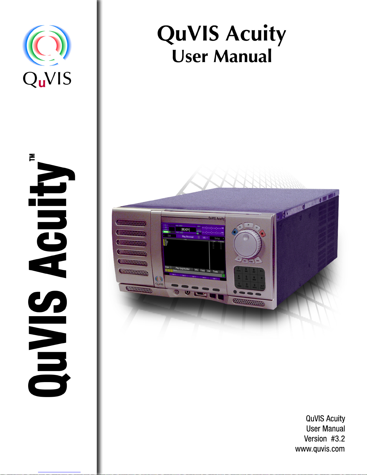
Serial Digital video Input/Output connections (standard)
The QuVIS Acuity Serial Digital Interface (SDI) connectors support both High Definition (HD-SDI) as well as
Standard Definition (SD-SDI) video on the same connection, although only one vi deo standard may be used at any
one time. As indicated in the diagram below, there are actually two sets of output connectors (SDI Out 1 and SDI
Out 2). This enables the same video signal to be routed to two different monitors or input devices at the same time.
There are two BNC connectors for each set of serial digital input and outputs. The connector labeled “A” is the
primary output connector or “Link A”. The connector labeled “B” is used to carry supplemental video inform ation
when Alpha channel output is used (4:2:2:4) or as video “Link B” of a dual-link HD-SDI video mode (SMPTE 372M)
including 12-bit HD-SDI and 4:4:4 content.
Note: Dual-link HDSDI (4:4:4:4) functionality is not supported under all configurati ons. If you have questions
regarding the configuration of your QuVIS Acuity, please contact your QuVIS salesperson.
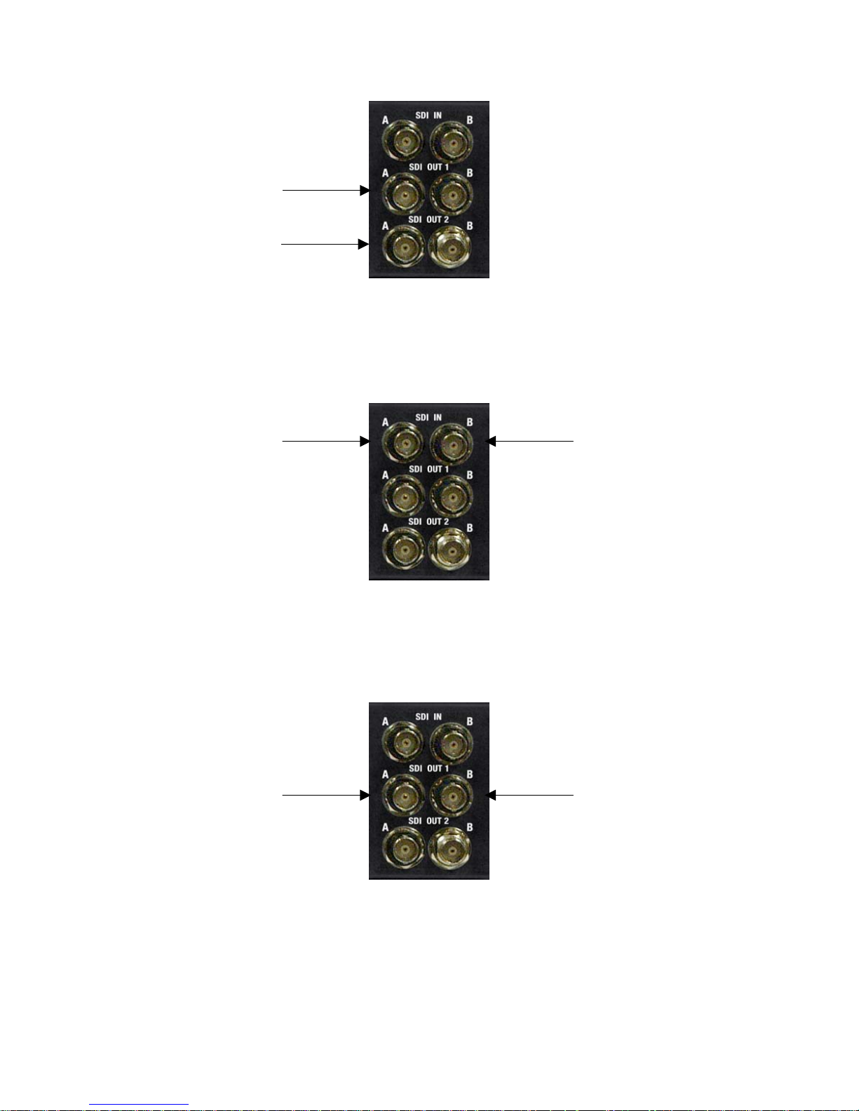
Serial Digital (SDI) 4:2:2 Input video connections
Connect your serial digital video cable to the BNC connector labeled “A” in the SDI IN connector group.
Connect SDI cable here.
Serial Digital (SDI) 4:2:2 Output video connections
Connect your serial digital video cable to the BNC connector labeled “A” in the SDI OUT 1 connector group.
QuVIS Acuity™ Page 13 QSR Version 3.3
Connect SDI output cable
here.
Connect optional secondary
SDI output cable here.
Dual-link SDI 4:4:4, 3D (4:4:4:4) or SMPTE 372M Input video connections
Dual-link video modes, including QPE and DCI JPEG2000 3D formats, require two SDI cable to complete input
video signal. Connect your primary SDI input cable to the link “A” connector. Connect the second output SDI cable
to the link “B” connector.
Connect SDI “Link A” here.
Connect SDI “Link B” here.
Dual-link SDI 4:4:4, 3D (4:4:4:4) or SMPTE 372M Output video connections
Dual-link video modes, including QPE and DCI JPEG2000 3D formats, require two SDI cable connections from the
Acuity to complete the video output signal. Connect your primary SDI output cable to the link “A” connector.
Connect the second output SDI cable to the link “B” connector. Alpha channel information is output on “Link B” for
those video modes that use it.
Connect SDI “Link A” here.
Connect SDI “Link B” here.
QuVIS Acuity™ Page 14 QSR Version 3.3
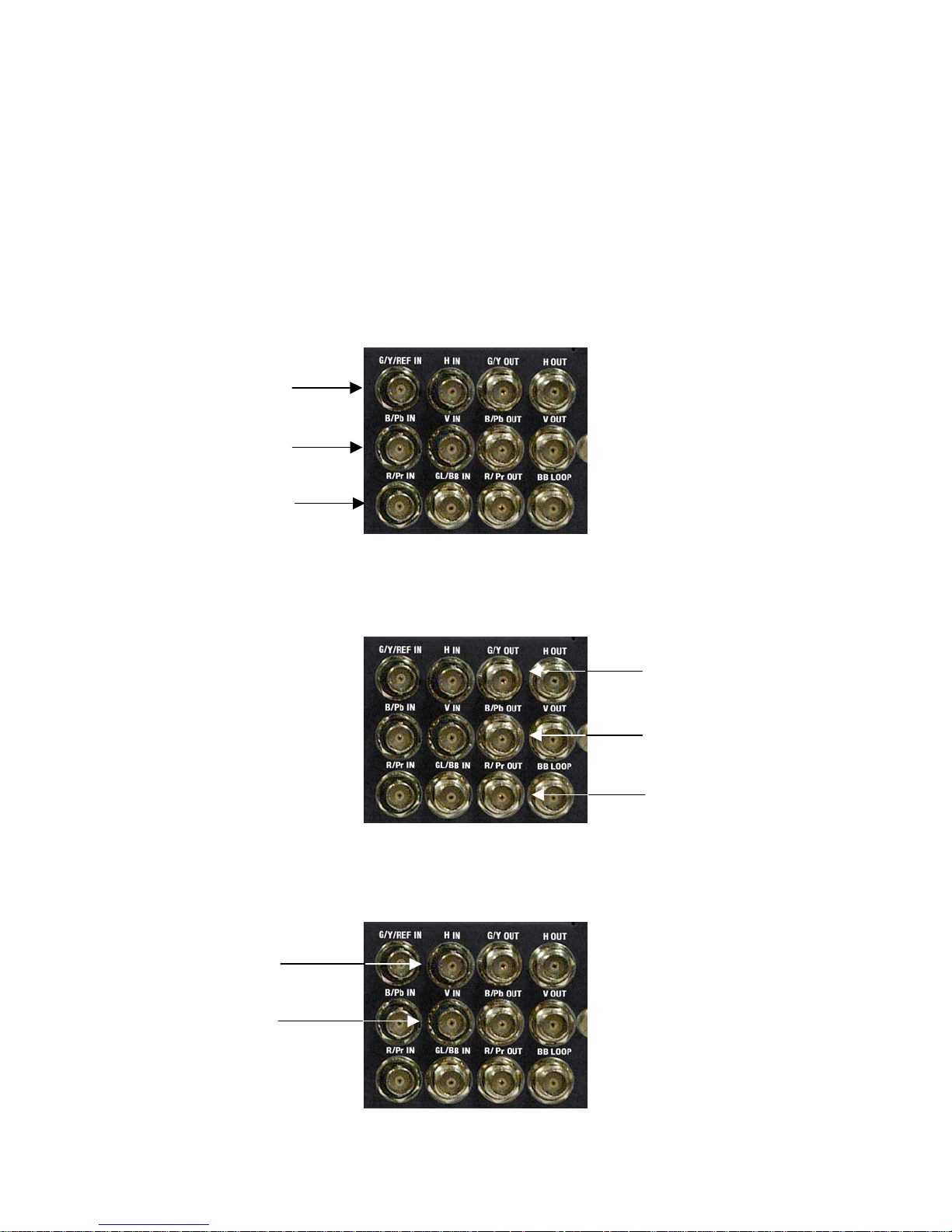
Analog video Input/Output connections (standard)
Analog Component video (input) is included (Analog Compo nent Output is optional) in the base configuration of the
QuVIS Acuity. Some analog video display applications require that sync signals be outp ut on sep arate outputs (H &
V). Please review your display requirements to ensure you have the appr opriate analog component cables (3-wire
or 5-wire).
Note: The Acuity’s ACO (Analog Component Output) module is not capable of supporting dual- link (SMPTE 372) or
Digital Cinema 2K (2048x1080) video modes.
3-Wire Analog Component Input (Sync on green) connections
For standard 3-wire analog component Input applications, make cable connections as follo ws:
Connect “green” channel
cable here.
Connect “Blue” channel cable
here.
Connect “Red” channel
cable here.
3-Wire Analog Component Output (Sync on green) connections
For standard 3-wire analog component Output applications, make cable connections as follows:
5-Wire Analog Component Input (separate sync) connections
For standard 5-wire analog component record (input) applications, make input Sync cable connections as follows:
Connect “Vertical” sync
cable here.
Connect “Horizontal” sync
cable here.
Connect “green”
channel cable here.
Connect “Blue” channel cable
here.
Connect “Red” channel cable
here.
QuVIS Acuity™ Page 15 QSR Version 3.3
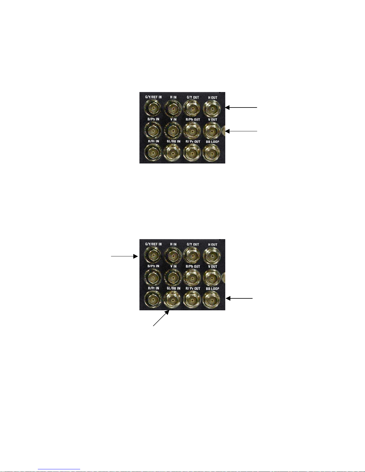
5-Wire Analog Component Output (separate sync) connections
For standard 5-wire analog component playback (output) applications, make output Sync cable connections as
follows:
Connect “Horizontal” sync
cable here.
Connect “Vertical” sync
cable here.
Reference video connections (standard)
The QuVIS Acuity provides both bi-level and tri-level Analog reference video inputs (Genlock) for those applications
that require video timing to be locked to a common (house) video signal. Standard definition video applications
(NTSC and PAL) normally use an analog Black Burst (BB) signal for reference. HD video applications typically use
analog Tri-level signal (sync on green) for video timing reference.
HD – Connect to
tri-level analog
reference signal
here.
SD - Connect to Black
Burst (Analog
Composite) reference
signal here.
To loop or pass the Black
Burst (Analog
Composite) reference
signal connect loop cable
here.
QuVIS Acuity™ Page 16 QSR Version 3.3
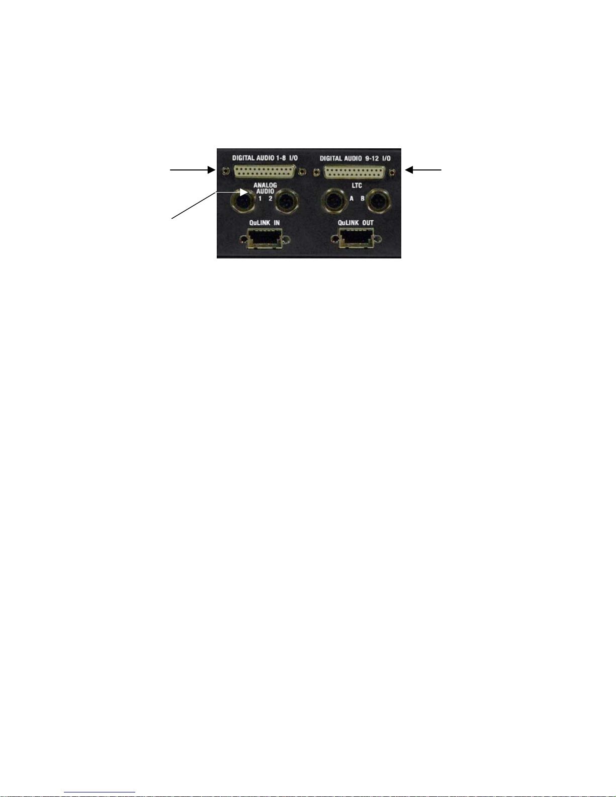
Audio output connections
The QuVIS Acuity audio system includes two analog audio channels or up to twelve channels of AES/EBU digital
audio. Both analog and digital audio channels one through eight (1-8) are grouped together and channels nine
through twelve (9-12) are grouped on the second digital audio connector.
Connect D-sub 25-pin
digital audio breakout
cable here for channels
1-8.
Connect analog audio
cables here.
Connect digital audio
breakout cable here
for channels 9-12.
QuVIS Acuity™ Page 17 QSR Version 3.3

Powering ON and Shutting Down
The following section describes the procedure for power on, restart and shutdown.
Turn ON Power
To turn on the Acuity, locate the front panel power button and press.
The power button is located under the front panel near the bottom left of the machine.
Power button
To shutdown or restart
Software shutdown
Use the following procedure to shutdown (power off) the Acuity from the front panel menu system:
1. Navigate to the Setup Info menu page.
QuVIS Acuity™ Page 18 QSR Version 3.3

2. Click on the Shutdown button using the pointer and center touchpad button.
3. A dialog window will be displayed to confirm your request to power down the Acuity. Press the Okay
button using the center touchpad button to continue.
Manual shutdown
To power off the QuVIS Acuity manually, press and hold the power button (located underneath the front panel) for 4
seconds.
WARNING! Do not attempt to power off the Acuity manually while the system is actively performing an
operation. To avoid the risk of electrical shock do not attempt to remove the power cord while the unit is
powered on.
Manual restart
To restart (reset power) the QuVIS Acuity manually, press and hold the first, second and fourth VTR transport
buttons (Stop, Rev and Fwd) for 3 seconds.
QuVIS Acuity™ Page 19 QSR Version 3.3
Configuring for basic PLAY operation
There are many aspects of the factory setup that may not apply to your installation or application. Therefore, you
will want to “walk-through” the main menu screens not only to setup the QuVIS Acuity for your application but also
to familiarize yourself with its broad feature set.
Use the following procedures to configure the QuVIS Acuity for basic playback operatio ns under local control.
For complete configuration procedures refer to Chapter 4 – Front Panel GUI Interface and Chapter 5 – Modifying
Configuration.
Configuration tasks:
• Select Video Output Settings
• Select Audio Output Settings
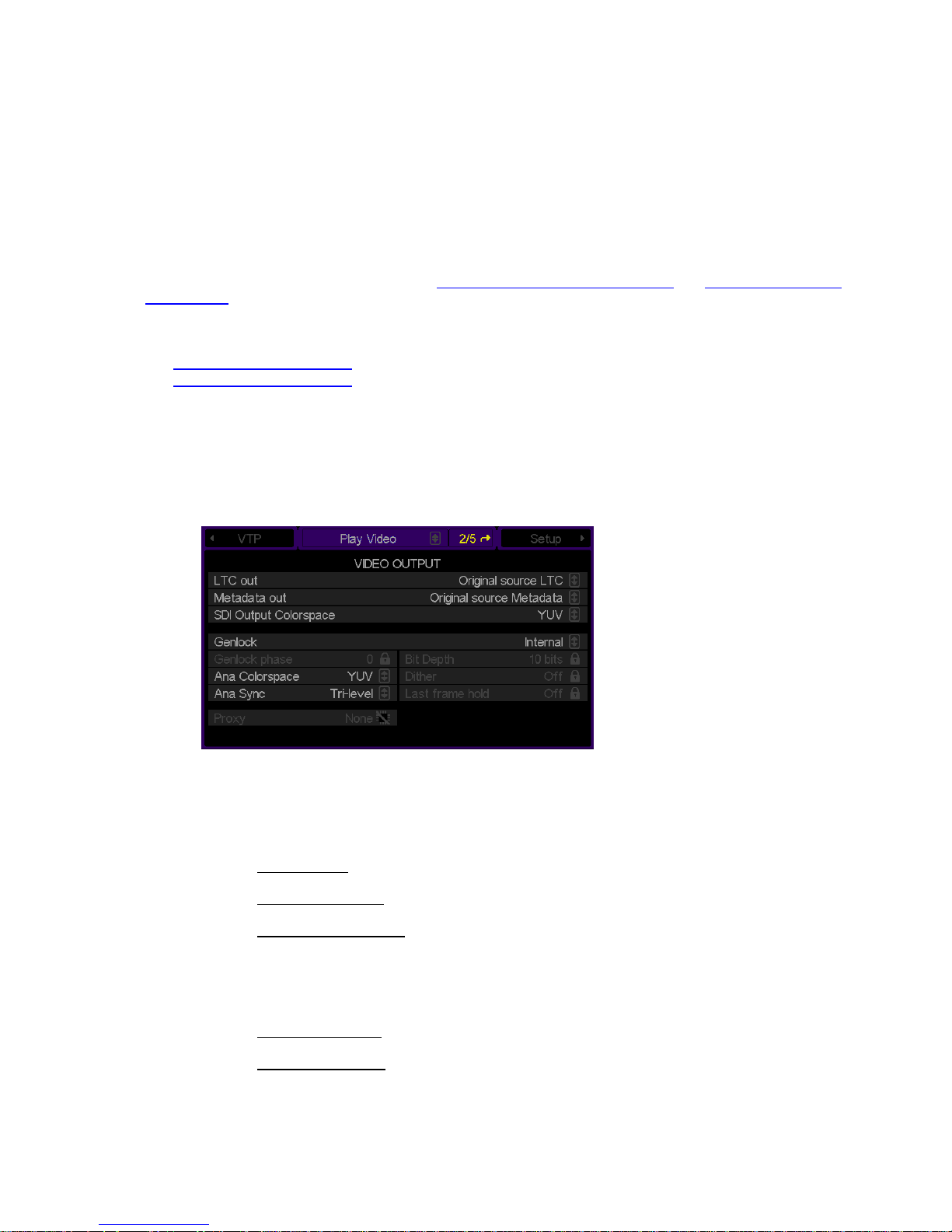
Select Video Output Settings
1. Navigate to the Play Video menu page.
2. Make the appropriate configuration changes in the Video Output section.
a. Set the LTC (Linear Timecode) out type.
No LTC output – No timecode will be output.
Original Source LTC
Absolute starting from 0 – Timecode starting at 00:00:00:00 will be output.
b. If playback is used in an editing environment, Metadata information (SMPTE RP-215) may be output.
Choices include:
Original source LTC
Same as LTC output
c. If necessary, set the SDI Output Colorspace.
QuVIS Acuity™ Page 20 QSR Version 3.3
– Recorded LTC timecode, saved as part of the media file, will be output.
– Timecode recorded as Metadata will be output.
– Use the same signal that LTC output is set to use.

d. Set the Genlock signal source (video reference).
e. If required, set the Genlock Phase.
Note: This control is used only to phase-in or delay the genlock signal (mainly analog) to compensate
for signal variations. This control should only be modified by qualified vid eo engineers. If the optional
Genlock hardware option is not installed, this control will not be accessible.
f. Set the output Bit Depth.
Note: This control is used to match the Acuity’s output signal to recording device that may only be
calibrated to accept a specific signal level. For most display applications this control will not need to
be modified.
g. Select output Dither if required.
Note: Dither adds a degree of digital-noise, or grain, to the playback. With some display devices the
effect yields a more pleasing playback image. In most cases, dither should not be used when the
video output is being displayed on a professional grade monitor or projection system. Dither is also
not recommended when dubbing content to recording device (the added noise can make for a poor er
signal). This control affects all outputs.
h. Set the Analog Colorspace to match the requirements of the display or input device.
The QuVIS Acuity can output analog video signals in either RGB (HV) or YUV colorspace. This
flexibility enables the Acuity to send the proper signal type to a wide range of display analo g devices
like CRT-based monitors, LCD monitors, plasma displays and projectors.
Note: This setting immediately affects the video output. If the setting is modified during live playback,
the analog colorspace will immediately change to the new selection without needing to restart
playback.
i. Set Analog Sync to match the requirements of the analog display or input device.
Display devices may need a specific form of sync signal to show image properly. The type of sync
signal required is dependent upon the specific display or input devic e being used.
j. If you wish the display to hold on the last frame of video when playback is stopped, set Frame Hold to
ON.
QuVIS Acuity™ Page 21 QSR Version 3.3

Select Audio Output Settings
1. Navigate to the Play Audio menu page.
2. Make the appropriate configuration changes Audio Output options.
a. To route audio channels to the analog stereo output (for monitoring), set the Analog Left/Right Mix
controls.
The combination of these two controls enables multiple audio channels (analog or dig ital) to be routed
to the analog channel pairs. Both analog audio channels may be monitored from the front panel using
the headphone stereo output jack.
b. The volume level for individual channels may be set from the Audio Meters control.
c. Use the Headphone Vol control to set the volume level for analog headphone output (stereo jack is
located on the front of the QuVIS Acuity).
d. Use the Master volume control to set the volume level for all audio channels. This control is additive,
meaning that if the volume level for individual channels has been set then the master volume control
will use modify each channel in relation to where it is currently set.
Example: If audio channel 1 is set to +5 and the master volume control is set to 50%, the cumulative
result is that channel 1 will be set to +2.5 or 50% of +5.
e. Set the Master frame delay (if necessary).
This control is used to compensate for timing errors between video and audio normally caused by
external equipment that use frame buffers while routing or converting video or audio.
QuVIS Acuity™ Page 22 QSR Version 3.3
Configuring for basic RECORD operation
There are many aspects of the factory setup that may not apply to your installation or application. Therefore, you
will want to “walk-through” the main menu screens not only to setup the QuVIS Acuity for your application but also
to familiarize yourself with its broad feature set.
Use the following procedures to configure the QuVIS Acuity for basic record operations u nder local control.
For complete configuration procedures refer to Chapter 4 – Front Panel GUI Interface and Chapter 5 – Modifying
Configuration.
Configuration tasks:
• Select Video Input Settings
• Select Advanced Video Input Settings
• Select Audio Input Settings
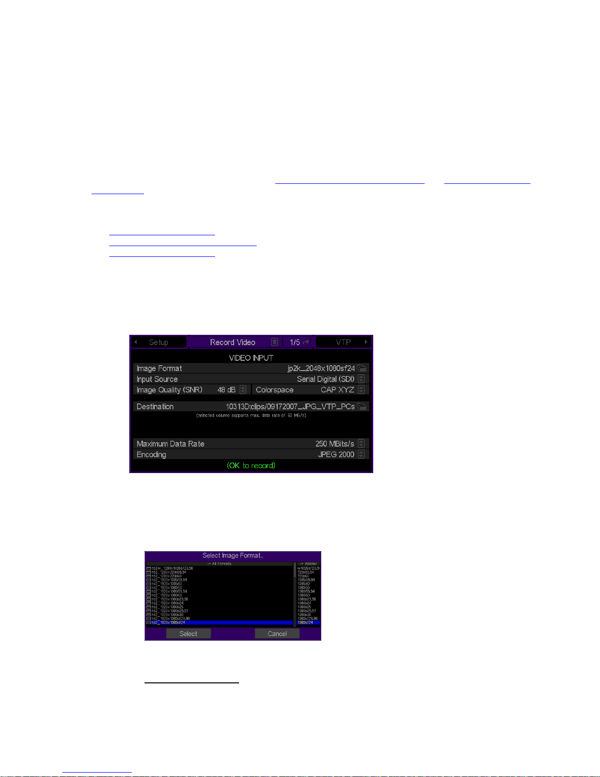
Select Video Input Settings
1. Navigate to the Record Video menu page.
2. Make the appropriate configuration changes in the Video Input section.
a. Select the image format file that matches the material you wish to record (a format file defines the
height, width and frame rate of a recorded signal).
b. Select the appropriate Input source according to the input format.
Serial Digital Input (SDI) – This option is used to record either a Standard Definition or High Definition
serial digital input signal.
QuVIS Acuity™ Page 23 QSR Version 3.3

Analog
– This input is used to record an Analog Component Video signal (YUV/YprPb).
c. Set the Image Quality (SNR) setting for recorded material. The typical setting used in a production
environment ranges from 51 – 63dB. The higher the number the higher the quality and larger the data
set.
d. Select the input Colorspace.
e. Select the Destination (volume and directory) where recorded assets will be stored.
f. The QuVIS Media Format is a compatibility switch that identifies QuVIS generational file format
standards.
Select QMF2 if the recorded media file needs to be backward compatible with the QuBit 2.x product
line (QuBit ST, EL and DS running QSR 2.3 or higher).
Select QMF3 for JPEG2000 formats.
For additional information, see the QuVIS Media Format (QMF)
in Chapter 3.
g. Set the Maximum Data Rate (MDR) setting. MDR is used to set the upper data rate limit when
recording. For additional information, see the Maximum Data Rate (MDR)
Select 250Mbit/sec for JPEG2000 formats.
Note: Additional consideration must be given to the number of drives that make up the destination
volume. A single-drive volume will not support data rates that exceed 30MB/sec.
section in Chapter 3.
QuVIS Acuity™ Page 24 QSR Version 3.3

Select Advanced Video Input Settings
1. Navigate to the Record Video Adv menu page.
2. This menu page provides advanced control over record input settings.
a. Using the Clip form control, select whether the recorded clip is to be collapsed or expanded.
Collapsed means the video and audio data exist in an interleaved format within the clip file structure.
Expanded indicates that the clip exists as a number of distinct media files with a separate video track
and some number of audio tracks.
Note: This setting is not available for any media file types. For instance, if the QuVIS Media Format is
set to QMF1, only collapsed clips may be recorded.
b. The Include metadata control is used to instruct the system to record a specific area of the incoming
serial digital stream as metadata. When metadata is present in the input stream, the metadata
presence indicator (M) on the dashboard will illuminate.
c. Noise coring is an advanced setting that is used to reduce low amplitude, high frequency signa ls.
Dither, film grain and other sources of electronic video “noise” are examples of what can be reduced
using this setting.
d. Select which Timecode input source should be used for recorded timecode. Choices include the LTC
input or the internal timecode clock.
e. Drop Frame Mode allows you to select the default timecode type that is built-in to the selected image
format or override it with a custom setting.
f. The 3D Format control is used to instruct the system the selected 4:4:4:4 format is to record the
incoming signal as two separate 4:2:2 channels for 3D QPE recording purposes.
QuVIS Acuity™ Page 25 QSR Version 3.3

Select Audio Input Settings
1. Navigate to the Record Audio menu page.
2. If required, modify audio input settings.
a. Audio form may only be used when the Clip form is set to “expanded”. This control is used to define
the way each channel of audio is stored, typically only done in an editing environment. Choices
include:
Audio Cluster (grouped channels) – A single file is used to store all selected audio ch annels.
Audio Tracks (discrete channels) – A separate file is used to store each selected channel of audio.
b. Use the Digital audio inputs and Analog audio inputs to specify which audio channels should be
recorded and whether channels 1 and 2 should be analog or digital.
c. If channels 1 and 2 are selected to be analog channels, the Level control is used to set the level of
attenuation for the analog channels.
d. Select the Resolution of the recorded audio signal. Choices include 16, 20 and 24 bit.
e. Select the sampling Frequency of the recorded audio signal. Choices include 44.1 kHz or 48 kHz.
f. Select the audio Format.
The Wave audio format is required for JPEG2000 record projects.
g. If necessary, use the Input audio delay to set the number of frames needed to compensate for audio
routing.
QuVIS Acuity™ Page 26 QSR Version 3.3

Verifying Basic Operations
Play a short clip to confirm that your connections and system setup are correct.
Refer to Chapter 2, Quick Start Procedures
for play and record procedures.
QuVIS Acuity™ Page 27 QSR Version 3.3

Setting up the Ethernet Network
The QuVIS Acuity factory assigned network settings will likely differ from your network-addressing scheme. Before
you connect the Acuity to your network, you will need to power it on and adjust the network address settings.
This procedure guides you to relevant network settings, but does not instruct you on the specific settings required
for your network. It is assumed that you understand Ethernet networks in general and your particular network needs
and that you can apply that understanding to make the required settings. If you need help with these procedures,
contact your network administrator.
Once the networks settings have been made and the appropriate connections made and verified, you can perform
the following tasks:
• Remote system management or control using Telnet or Acuity API calls.
• General networking tasks such as data file sharing using an FTP client.
• CGI-based clip creation/extraction (QuApps)
• Media file sharing between QuVIS video servers or networked computers.
Procedure Summary:
• Configure the QuVIS Acuity Network Settings
• Connecting the Ethernet Cable
• Verify the Ethernet Connection
QuVIS Acuity™ Page 28 QSR Version 3.3

A
Configure the QuVIS Acuity Network Settings
Network settings may be assigned using the front panel interface display. You will lik ely find it easier to configure
the network settings using a PS2 keyboard attached to the front panel of the QuVIS Acuity. The system must be
restarted in order for the new settings to take affect.
QuVIS servers configured with a CPU version 7 include two (2) Gigabit Ethernet ports. This dual-port configuration
allows the server to be operated in a Digital Cinema production environment where each network port is assigned
to serve dedicated functions. “LAN 1” is configured for Data traffic (i.e. network data transfers, Telnet, FTP, API,
etc.). “LAN 2” can optionally be configured as a projector port used to communicate with a Digital Cinema projector
(i.e. CineCanvas, CineLink, projector commands, etc.).
Older CPU versions (e.g. CPU version 6.x) that are configured with a single network port are still active. Network
configuration settings for the second port may not be viewable on those single-port servers.
Network TCP/IP address settings may be manually assigned using the front panel GUI. Alternately, the QuVIS
Acuity can use the DHCP (Dynamic Host Configuration Protocol) network service to receive its IP addressing
information (IP address, subnet mask, default gateway) from a network server. The QuVIS Acuity is assigned an
unused IP address from a pool of TCP/IP address maintained by the DHCP server.
DHCP provides safe, reliable, and simple TCP/IP network configuration, prevents address conflicts, and helps
conserve the use of IP addresses on the network. If the QuVIS server is connected to a foreign network running
DHCP, an IP address may be automatically assigned by the network without having to request an IP address from
a company’s IT department.
To enable DHCP IP address assignment click on the DHCP control on the Setup Network (4/8) menu page.
Modifying Network Settings
TIP: Network settings are saved in non-volatile memory. In order to activate changes to network settings, the
cuity must be restarted. Each time a network setting is changed, a prompt is displayed asking if you would like
to restart the unit now to activate the changes. If you need to change multiple settings, do not choose to restart
the unit until after the last setting is changed.
If the QuVIS server is configured with a CPU version 7, the Setup Network menu page will include a second
column of settings used to configure the second network port. If the installed CPU card is not configured with 2
ports (i.e. CPU version 6), only the settings for LAN port 1 may be viewable or settable.
Use the following procedure to change the network settings for either Gigabit Ethernet port (LAN 1 or LAN 2).
1. Power on the Acuity.
2. Navigate to the SETUP - Network menu page.
QuVIS Acuity™ Page 29 QSR Version 3.3

3. To change the IP Address, using the touchpad place cursor over the appropriate control and press the center
touchpad button to activate the input window.
Note: You will likely find it easier to configure the network settings using a PS2 keyboard that may be attached
to the front panel even while the Acuity is turned on. A network address is composed of four parts (octets)
separated by a period. To modify the next part (octet) of the network address you must use the period (.) button
to advance.
4. To change the Subnet Mask, place the cursor over that menu item and press the center touchpad button to
activate the input window.
5. To change the Default Gateway setting, place the cursor over that menu item and press the center touchpad
button to activate the input window.
6. Restart the system to activate the network changes.
QuVIS Acuity™ Page 30 QSR Version 3.3
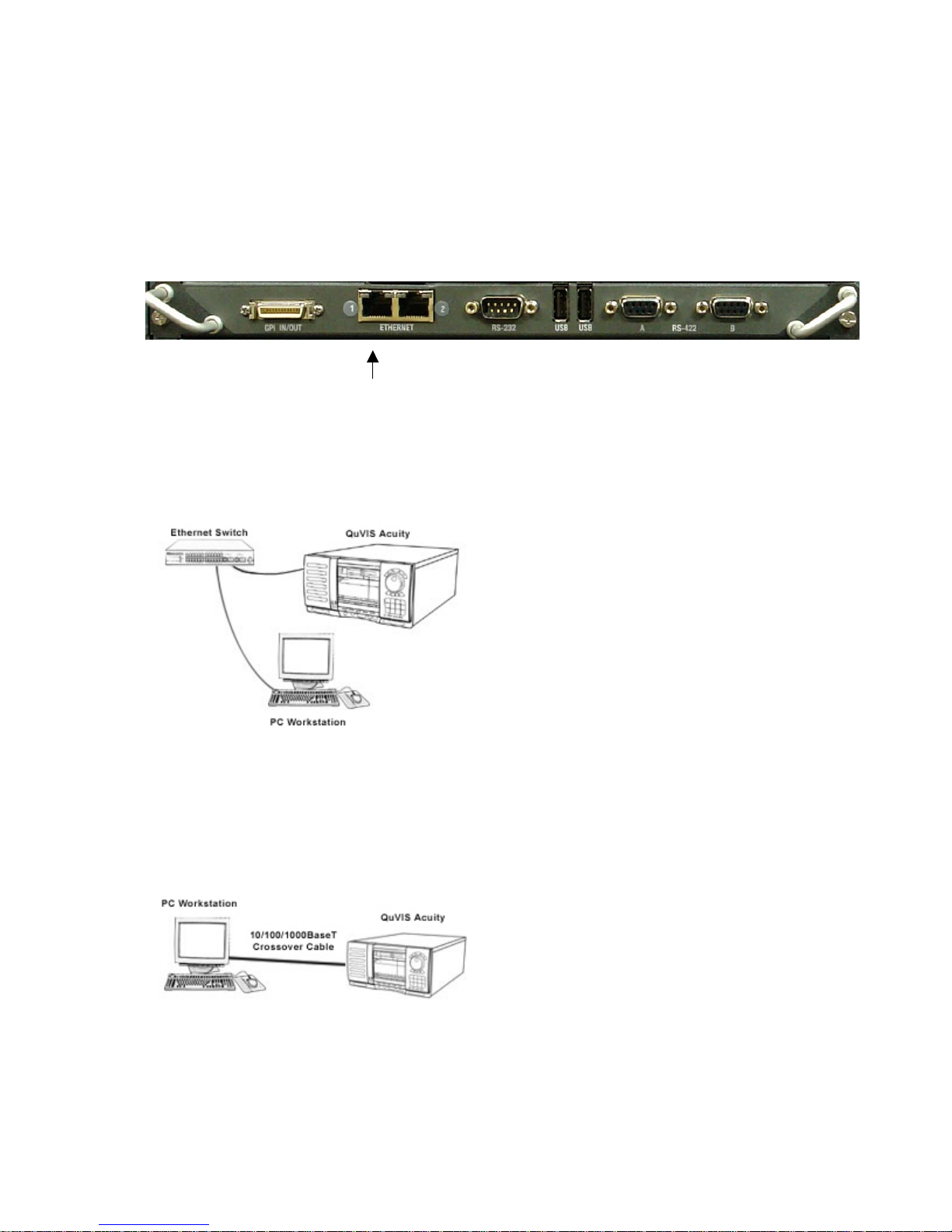
A
Connecting the Ethernet Cable
The QuVIS Acuity has a built-in 1000BaseT (Gigabit) Ethernet card that is used to connect to a standard Ethernet
network. The network adapter auto-senses the connection speed and is fully compatible with 10, 10 0 and
1000BaseT networks. The Acuity uses the standard RJ-45 Ethernet connector that accepts either CAT 5 or CAT 6
twisted pair Ethernet cables.
The QuVIS Acuity’s network cable port is located on the back of the unit on the bottom board module.
Connecting to a network hub or switch
Use a standard straight Ethernet cable to connect the QuVIS Acuity to a hub or central switch.
ttach RJ-45 Ethernet cable here (Port 1).
Connecting directly to a computer
To bypass the need for a network hub or switch, a network crossover cable may be used to connect a c omputer (or
other network device) directly to the QuVIS Acuity.
Notes:
QuVIS Acuity™ Page 31 QSR Version 3.3

• The QuVIS Acuity will auto-negotiate Gigabit Ethernet (1000BaseT) connections using either a straight or
crossover Ethernet cable. In general, 10/100BaseT Ethernet connections will require the use of a
crossover cable to communicate with the Acuity without the use of a hub or switch.
IMPORTANT! If the communication between a PC workstation and a QuVIS Acuity is expected to support data
transfers of media files (clips), a network switch must be used to ensure reliable transfers.
Verify the Ethernet Connection
When the system is properly connected to the network, the green indicator on the Acuity’s network port will light up
to indicate a proper connection. The yellow activity lamp will also periodically illuminate if other devices are currently
on the network.
Verify the Acuity’s Ethernet connection and presence on your network by either “pinging” the Acuity’s IP address or
opening a client connection using a Telnet or FTP client. If the QuVIS Acuity responds to the “ping” reques t or you
are able to successfully establish a Telnet or FTP connection, the QuVIS Acuity and the network are functioning
properly.
TIP: If you are unable successfully communicate with the QuVIS Acuity, please check to verify that the network
settings are appropriately assigned. Communication problems will occur if two or more devices on the network
as assigned the same IP address. If the network setting are correct, and problems still exist, check the cabling as
well as the network settings of the computer trying to establish the connection. If problems still exist contact your
network administrator or QuVIS Customer Support for assistance.
QuVIS Acuity™ Page 32 QSR Version 3.3
A
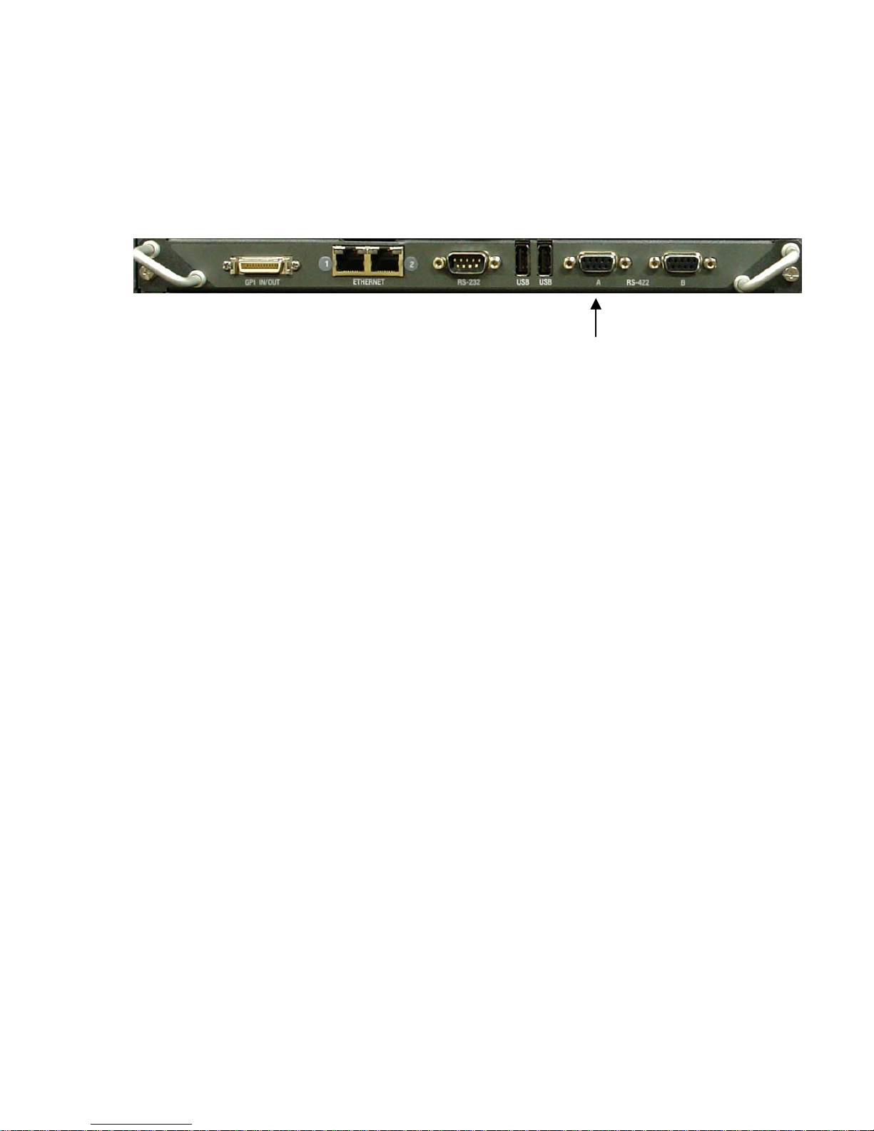
Connecting Serial RS-422
The QuVIS Acuity may be controlled using remote control devices and applications software that uses the industry
standard RS-422 serial protocol. To operate the QuVIS Acuity remotely using the RS-422 protocol, a RS-422 cable
(male) must be connected to the Acuity and the controlling device. Connect the RS-422 cable as required.
ttach RS-422 serial
cable here.
QuVIS Acuity™ Page 33 QSR Version 3.3

CHAPTER 2 – QUICK START PROCEDURES
Procedures in this chapter include:
• Play a clip from the GUI
• Record a clip from the GUI (Local record)
• Basic file management
QuVIS Acuity™ Page 34 QSR Version 3.1

Play a clip from the GUI
The procedure for playing a clip remotely using the remote “desktop” software, QuVIS QuDAC™, is the same as
playing a clip or media file from the panel of the Acuity.
1. Navigate to the Play Browser menu page.
TIP: If the Play Browser menu page is not the active screen, you can press the VTR PLAY button as a
shortcut to the load the Play menu group.
2. Navigate to the file directory that contains the clip you wish to play.
Note: Directory navigation on the Acuity is similar to navigating directories on a computer. To open a directory,
place the pointer on the directory you wish to open and press the center touchpad button.
3. Select the clip(s) you wish play by placing the pointer over the desired clip and press the center touchpad
button.
Note: Multi-file playback is only supported if the playstyle (Style control) is set to Play select item.
TIP: If you wish to change the playstyle, click on the Style button and select the desired playstyle from the list.
QuVIS Acuity™ Page 35 QSR Version 3.3

4. To play the selected clip or media file, press the VTR PLAY button.
Note: The QuVIS Acuity will automatically switch to the appropriate output video format (if needed) before
playback will begin.
QuVIS Acuity™ Page 36 QSR Version 3.3

Record a clip from the GUI (Local record)
To record a clip from the GUI, the QuVIS Acuity must first be configured to match the format settings of the source
material (including video, audio and timecode). Before you begin make sure that the video, audio and LTC timecode
(if required) input connections to the QuVIS Acuity are properly connected to the content source.
1. Navigate to the Record Video menu page.
TIP: If the Record Video menu page is not the active screen, you can press the VTR REC button as a
shortcut to the load the Record menu group.
2. Review the current record settings to ensure that the Acuity is properly configured to accept the video and
audio format of the source material. You may need to modify the following settings found on the specified menu
pages:
a. Image Format (Record Vi deo 1/5)
b. Digital audio inputs (Record Audio 3/5)
c. Analog audio inputs (Record Audio 3/5)
d. Resolution (Record Audio 3/5)
e. Frequency (Record Audio 3/5)
3. Review the additional system systems to ensure that the Acuity is properly configured to record content with
the correct parameters for this specific project. Settings that should be review are as follows:
a. Image Quality (Record Video 1/5)
b. Colorspace (Record Video 1/5)
c. Destination (Record Video 1/5)
d. QuVIS Media Format (Record Video 1/5)
e. Maximum Data Rate (Record Video 1/5)
f. Quality Priority Encoding (Record Video 1/5)
g. Clip Form (Record Video Adv 2/5)
h. Timecode (Record Video Adv 2/5)
TIP: If you have already saved a config files that contains the settings for your project, you can load the
required record settings in a single step. See Load custom settings from a config file
for additional details.
QuVIS Acuity™ Page 37 QSR Version 3.3
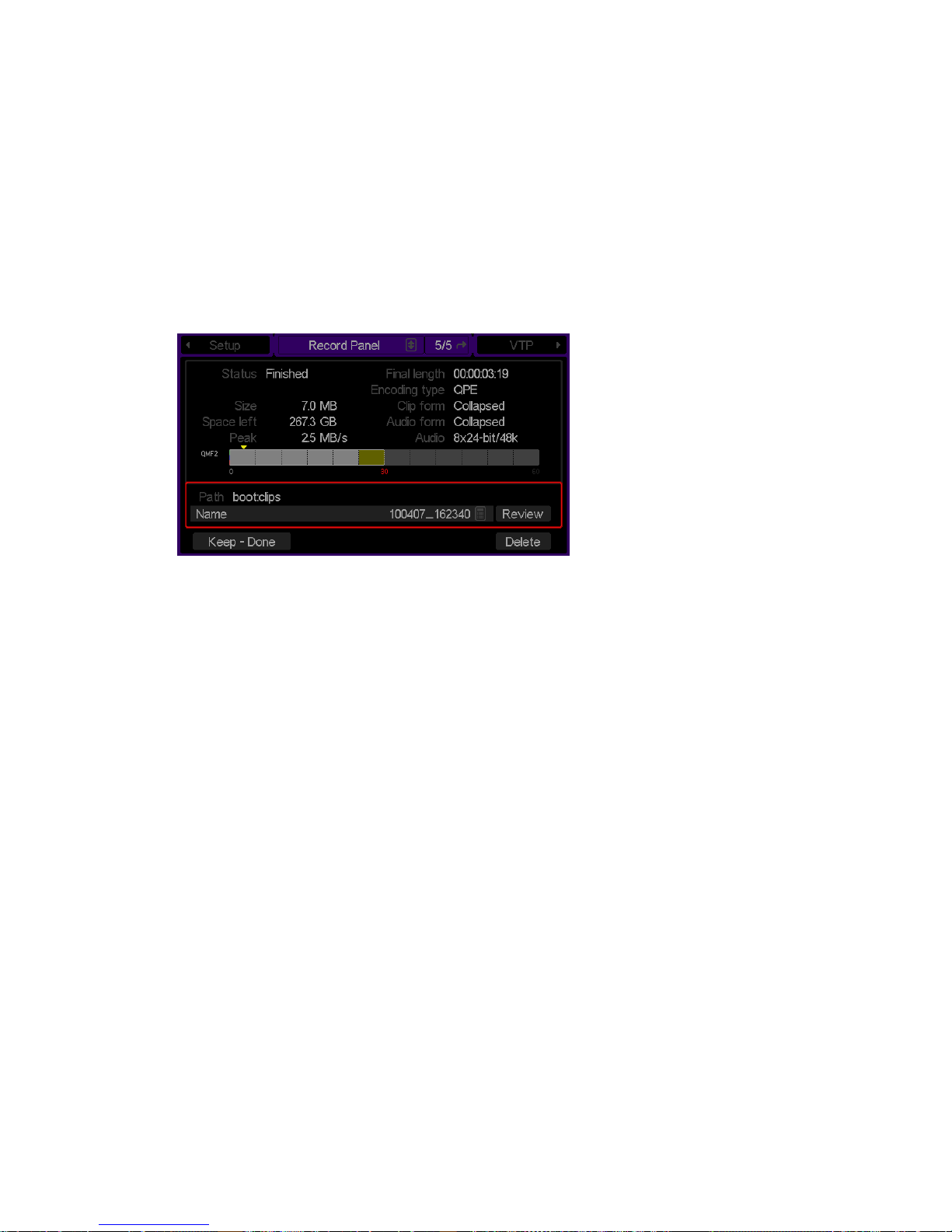
4. To record a clip from the GUI, press the VTR REC button to place the system in a record-ready state. The
system will load the appropriate video format and will update the Transport Status indicator in the dashboard to
read [Record].
5. Press REC+PLAY to begin recording. The GUI will automatically switch to the Record Panel menu page so
that the record process may be monitored.
6. To stop recording, press the VTR STOP button.
7. Once recording has stopped you may chose to review (play) the clip, rename it, delete the clip or accept (Keep)
the recording.
QuVIS Acuity™ Page 38 QSR Version 3.3
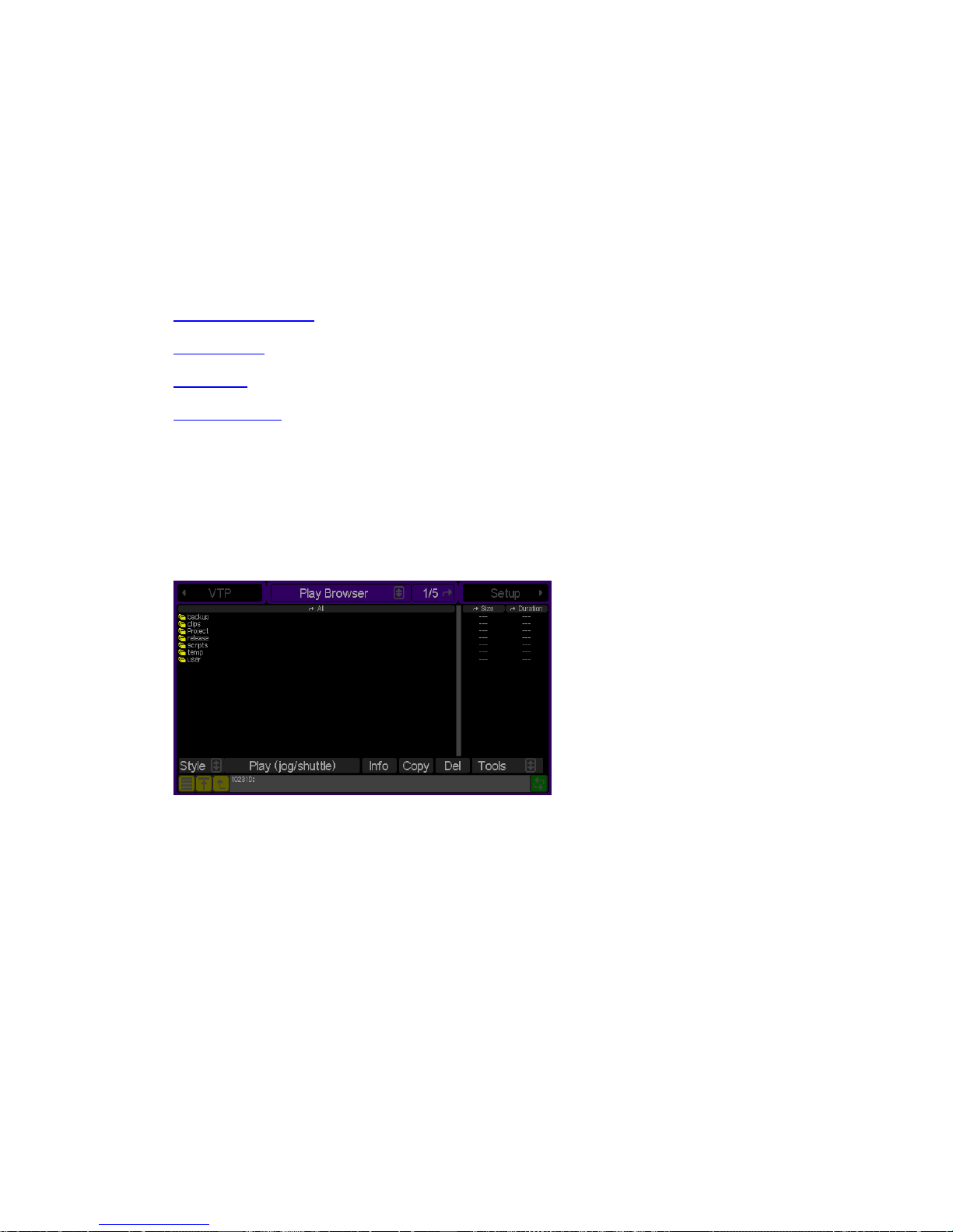
Basic file management
Basic file operations may be performed directly from the front panel GUI of the QuVIS Acuity. This includes the
ability to create directories as well as copy, rename and delete files. This section will cover the basic local file
operations.
The Play Browser menu page provides the ability to conduct file management operations.
File Management Tasks:
• Create a new directory
• Rename a File
• Delete a file
• Copy a file (local)
Create a new directory
1.
Navigate to the Play Browser menu page.
2. Navigate to the volume and/or directory path where you wish to create a new directory.
3. Click on the Tools button to activate the list of additional file operations.
4. To create a new directory, select the Make directory operation choice from the popup window and press the
center touchpad button.
5. Using the touchpad (or PS2 keyboard if attached) enter the name of the new directory.
Note: Directory names can be up to 40 characters in length.
QuVIS Acuity™ Page 39 QSR Version 3.3
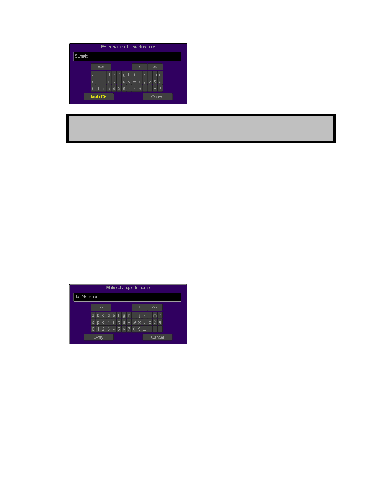
TIP: As you place the pointer over each character to be added to the directory name you may either press
the center touchpad button to select or simply tap on the touchpad if the Touchpad Tap functionality is
enabled.
6. To complete the operation, click on the MakeDir button. If you wish to cancel the operation, click on Cancel.
Rename a File
1.
Navigate to the Play Browser menu page. .
2. Select the file or directory you wish to rename using the pointer and the center touchpad button. Once the file
has been highlighted it is ready to be renamed.
3. Click on the Tools button to activate the list of additional file operations. To rename the selected file, select the
Rename operation choice from the popup window and press the center touchpad button.
4. Using the touchpad (or PS2 keyboard if attached) rename the file. Use the arrow button to backspace through
the current filename or press Clear to blank the filename.
Note: File names can be up to 110 characters in length.
5. To complete the operation, click on the Okay button. If you wish to cancel the operation, click on Cancel.
QuVIS Acuity™ Page 40 QSR Version 3.3

Delete a file or directory
1.
Select the file or directory you wish to delete by placing the pointer over the file and pressing the center
touchpad button. To select a directory for deletion place the pointer over the directory name and press the right
touchpad button.
Note: A directory must be empty of all files and subdirectories before it can be deleted.
TIP: Multiple files may be deleted in a single operation provided that all the files to be deleted have been
selected/highlighted.
2. To delete the selected file or directory, click on the Del button.
3. Using the pointer and the center touchpad button, click on the Okay button to complete the del eted operation.
Copy a file (local)
From the Play Browser menu page, select the file you wish to copy using the pointer and the center touchpad
1.
button.
TIP: Multiple files may be copied in a single operation. To select multiple files, click on the first file
and continue to hold down the center touchpad button and drag the pointer (using the touchp ad)
over the additional files to be copied. Release the touchpad button to complete the multiple file
selection.
2. To copy the selected file(s), click on the Copy button.
3. Select the destination (the directory where the copy of the selected file will be placed) by navi gating to the new
directory location using the file browser popup window. Any local directory may be selected as the destination
even if it is located on a different storage volume.
TIP: To copy a file to another QuVIS video server (QuVIS Acuity, QuBit ST, QuVIS Encore, etc.)
click on the world icon to list the available networked servers. Select a networked server from the
list and set the directory destination for the remote copy operation.
4. Click Okay button to start the copy process.
Note: To cancel the operation, click on the Cancel button. If multiple files have been selected to copy,
canceling the current operation will stop all subsequent copy operations.
QuVIS Acuity™ Page 41 QSR Version 3.3

CHAPTER 3 – PRODUCT DESCRIPTION
Information in this chapter includes:
• Product Overview
• Storage
• System Security Features
• Image Processing
• QuVIS Media file types
• QuVIS Image Format Files
• QuVIS Acuity and Digital Cinema Content Mastering
• Factors that affect picture quality when Recording
• Factors that affect picture quality during playback
• Server Status Web Page
• Control Panel Overview
• Introduction to the Graphical User Interface (GUI)
QuVIS Acuity™ Page 42 QSR Version 3.1

Product Overview
In 2003, the QuVIS Acuity was introduced as the next generation multi-format digital video mastering server. At that
time, content producers were in the process of transitioning from Standard Definition (SD) to High Definition (HD)
production and the large-scale adoption of Digital workflows was in full s wing. The QuVIS Acuity’s revolutionary
Virtual Tape (VTP) architecture provided a bridge between tape-based workflows and online digital production.
In 2005, a collaboration of movie studios published the framework of Digital Cinema content specifications and
adopted JPEG2000 as the image-encoding standard. Many elements of these recommendations have undergone
formalization through the SMPTE standards committees and are now industry specifications. With the formalization
of these standards, Digital Cinema as an industry has taken flight and the global initiative to transition film-based
theaters to Digital Cinemas is well underway.
Content production for the Digital Cinema industry has largely been a computer or file-based process. In part this
has been due to the lack of mastering hardware capable of encoding JPEG2000 content in real-time prior to the
standards and workflows being formalized and implemented. While other hard ware man ufacturers have made
strides in providing hardware-based solutions, they have continued to fall short of reliable real-time encoding. T hat
is, up until the QuVIS Acuity.
In 2007, the QuVIS Acuity has undergone a generational evolution to provide a cutting-edge mastering platform for
a revised Digital Cinema and post-production industry. At the core of the QuVIS Acuity a new Video Signal
Processor (VSP – version 9) enables the Acuity to not only be the first digital video-mastering server capable of
real-time JPEG2000 and QPE™ encoding (real-time record) but also to provide the power and flexibility to support a
powerful feature set not available on any other server.
The QuVIS Acuity has been upgraded to provide the most advanced mastering capabilities: this new feature set
includes mastering support for Standard Definition (SD), High Definition (HD), 2K and 4K formats in the most
comprehensive variety of encoding levels, color sampling, frame rates, color spaces, and scanning options
available today. The advanced Digital Cinema mastering features available on the Acuity platform include: Realtime DCI 2K JPEG2000 Acquisition and Playback, Real-time DCI AES Encryption, Real-time Composition Timeline
Editing and Preview, Real-time QuVIS TitleMaster™ (server-based) DCI Subtitle rendering, and Real-time Input and
Output Colorspace Conversion.
In addition to providing a comprehensive DCI JPEG2000 mastering platform, the QuVIS Acuity continues to offer
the patented and widely accepted wavelet-based im age encoding method, QPE (Quality Priority Encoding), that is
both visually lossless and more efficient than other commercial solutions available today. QPE remains the optimal
choice for reducing online storage requirements while guaranteeing the h ig hest image quality possible.
The QuVIS Acuity offers 16 independent digital, format free audio I/O channels with a choice of 16 or 24-bit audio at
44.1 and 48 kHz allowing the ability to sync audio to video clips recorded at any frame rate.
The QuVIS Acuity offers transparent support for a complete SD, HD or Digital Cinema digital workflow. Beginning
with acquisition and throughout the post process, from color correction to DSR (Dirt and Scratch Removal), editing,
effects, audio processing finishing and optional down conversion for distribution, QuVIS can integrate with or
replace equipment within of existing systems.
Unique to the QuVIS Acuity, the newly enhanced Virtual Tape Editor (VTP Editor) provides complete access to
timeline assets and control of Composition layout for both JPEG2000 and QPE projects. This powerful interface is
invaluable for accurately editing track assets, track asset timing and subtitle track positioning, and adjusting sync
points. Enhanced by the QuVIS TitleMaster subtitling and Output Colorspace Conversion engines, virtu al tape
projects, with or without subtitles, can be accurately previewed on a wide range of HD-SDI display devices in the
native colorspace of the display. This means there is no longer a need to tie up a Digital Cinema screening room
and projector just to make sure that a composition tracks are properly synchronized or that subtitles are timed
correctly. This flexibility provides complete real-time preview and adjustment capabilities during the mastering
process not available on any other Digital Cinema mastering solution.
Combined with network-based remote front panel GUI access, the multitude of mastering features, scalability, and
comprehensive professional I/O options, the QuVIS Acuity is the most comprehensive and cost-effective Digital
Cinema mastering platform available on the market today.
QuVIS Acuity™ Page 43 QSR Version 3.3

Storage
The QuVIS Acuity is configured with 4 internal and external LVD SCSI buses or channels, each capable of
supporting up to 14 devices including: internal SCA media drives, hot-swap removable hard drives and 8mm data
tape drives. Internal media drives are used to record and play video and audio in real-time. Remova ble hard drives
may also be used to record, play and archive content or to share content between similarly equipped QuVIS video
servers. Tape drives (Sony AIT) may be used to create an off-line archive of content for long-term storage or to
share content between units.
QuVIS internal hard drive media storage is configured to stripe data across multiple hard drives, with each drive
residing on its own SCSI channel, configured as a single storage volume. For storage and bandwidth flexibility,
QuVIS video servers support various drive volume widths. The number of drives in a storage volume can vary,
depending upon determined bandwidth requirements, from one to four drives in a QuVIS Acuity. A single-drive
volume can be used to transport and share content between QuVIS video servers or to play content that is datarate limited, either by the video format, such as NTSC or PAL, or by QuVIS data-rate controls. A single-drive
volume will support a Maximum Data Rate (MDR) of 30MB per second or MDR30.
Multi-drive volumes may be used to store and playback high data-rate content such as the video format 720p60.
Multi-drive volumes may also be used to create very large storage volumes capable of recording many hours of HD
content on a single volume. The maximum data rate two-drive volumes can support on a QuVIS Acuity is limited to
60MB per second or MDR60.
Drive order within a “non-boot” volume is not important, as volume order is determined during the formatting
process. Once a volume is formatted, the user may remove the volume and place the drives back into the QuVIS
Acuity or a different Acuity, QuVIS Acuity or QuVIS Cinema Player in any order. The system will automatically
identify which drive is the proper logical drive in the stripe sequence. T his auto-sequencing feature is very useful
when using hot-swap removable drives allowing the operator to concentrate on the process and not the sequence
of drives that make up a volume.
Placement of a “boot” volume, volume that contains the system operating software, is important. The boot volume
should always be placed starting in the left-most two positions of the Internal Media Bays. Removing the boot
volume from the system will render the unit inoperable from a video record and playback standpoint. If a valid boot
volume is not detected the unit will still power on but the operating system will have limited functionalit y and
playback will be disabled.
To ensure that drive failure does not interrupt a mission critical workflow the QuVIS Acuity can be attached to a
highly reliable redundant external storage array, called a RAID array. RAID storage, or Redundant Array of
Inexpensive Disks, can be configured such that a single drive failure will not impede the ability to play content.
Using external storage arrays the QuVIS Acuity can support multiple Terabytes of online storage.
Volume Sizes
Internally, the size of storage volume can vary depending upon the size of the drive and the number of driv es in the
volume. Externally, the QuVIS Acuity can support even larger volume sizes, up to multiple TeraBytes (TB) of
storage, using approved multi-channel drive arrays.
Internal Media Bay Storage
The latest video server products from QuVIS (QuVIS Ovation, QuVIS Cinema Player, QuVIS Encore and QuVIS
Acuity) offer new internal storage architecture designed to enable front panel access to internal Media storage. This
new architecture allows QuVIS Media storage to be shared between these products by simply removing a volume
from one machine and placing it in the Media bay on another.
The QuVIS Acuity has eight internal Media storage bays. Each Media bay accepts SCA (Single Connector Adapter)
SCSI hard drives that are mounted on removable drive slides. Media drives are hot-swappable meaning that the y
may be inserted or removed while the unit is powered on. SCSI device ID assignment is handled automatically by
QuVIS Acuity™ Page 44 QSR Version 3.3

the system depending upon which media bay slot the drive is occupying. The diagram bel ow lists the SCSI channel
and device ID assigned to each Media bay.
Media Bay 8
Media Bay 7
Media Bay 6
Media Bay 5
Media Bay 4
Media Bay 3
Media Bay 2
Peripheral Bay
SCSI Channel 0x3
Peripheral Bay
SCSI Channel 0x2
Media Bay 1
SCSI Device ID - 0x32
SCSI Device ID - 0x22
SCSI Device ID - 0x12
SCSI Device ID - 0x02
SCSI Device ID - 0x31
SCSI Device ID - 0x21
SCSI Device ID - 0x11
SCSI Device ID - 0x01
NOTE: The default location for the primary boot volume (volume that hosts the Operating System files) is Media
Bay 1 and 2.
Removing Internal Media Drives
The QuVIS Acuity internal media drives are mounted on removable sleds that are locked into place using a sole noid
locking mechanism. Below each internal media bay is a “unlock” button and two LED indicators.
Procedure while the QuVIS Acuity is powered ON
To remove a drive sled from the media bay, the solenoid lock must first be disengaged. Use the following procedure
to remove a media drive while the system is powered on.
1. Lift up the front control panel and secure it in the raised position by tightening the armature screw (located
on the right side underneath the control panel).
2. Press the button directly underneath the drive sled you wish to remove. The operating system will now
prepare to the drive for removal by safety spinning down the drive. The lights will blink while the drive is
readied for removal. Once the drive is ready to be removed, the solenoid lock will be disengaged allowing
you to safely remove the drive sled.
3. To remove the drive sled (while the solenoid lock is disengaged), place your fingers i n the top and bottom
finger holes and pinch the tabs towards the center of the sled. While the tabs are held towards the center
of the sled, firmly pull the sled toward you in a straight motion.
Warning! If you attempt to remove a drive sled without the solenoid lock disengaged, you may
cause damage to the sled tabs.
QuVIS Acuity™ Page 45 QSR Version 3.3

Procedure while the QuVIS Acuity is powered OFF
To remove a drive sled from the media bay while the system is powered OFF, you must use the solenoid override
key to manually disengage the solenoid locks.
1. Place the solenoid override key (3/32 hex key) in the hole (center of media bay tray) just below the
solenoid disengage buttons.
2. Turn the key clockwise until it will no longer turn (about a quarter turn) and hold.
3. To remove the drive sled (while the solenoid lock is disengaged), place your fingers i n the top and bottom
finger holes and pinch the tabs towards the center of the sled. While the tabs are held towards the center
of the sled, firmly pull the sled toward you in a straight motion.
4. Slowly release the override key and remove.
Peripheral Bay Storage
The QuVIS Acuity accepts up to two 5 ¼” SCSI devices in the optional internal Peripheral Bay. The Peripheral Ba y
may be configured with a half-height (5 ¼”) removable drive assembly for transporting content between QuVIS
video servers. Alternately, the Peripheral Bay may be populated with an 8mm Sony AIT tape drive for transport and
archiving applications. The Peripheral Bay takes on the SCSI ID of the device that is installed in that slot.
Removable hard drive media allows the server to store all supported video formats to the same media without
requiring separate virtual or physical partitions of the drives for different clip/video formats. With scalable storage
options, several hours of superior quality high definition video can be shared between servers in just a matter of
minutes. With “hot-swap” removable drive support the dismounting and mounting of removable drive volumes can
be done live with the system powered on.
Archiving Data
Using native software tools, data and media files can be archived to or loaded from high-capacity 8mm tape b ackup
devices such as the Sony AIT-2/3 tape drive. A single AIT-3 tape cartridge can store up to 100GB of data or in
QuVIS terms, in excess of 2 hours of QPE encoded HD (1920x1080) playable media. Once data has been backed
up to this archive magnetic tape media, the content can be safely stored for long-term archiving or immediate offline retrieval.
USB 2.0 Drive Support
The QuVIS Acuity, configured with CPU version 7, provides two USB 2.0 ports used to connect external USB
storage devices. USB device support is currently limited to data storage devices such as USB thumb drives and
external USB hard drives.
Note: The QuVIS Acuity does not currently support local DCP Ingest from an external USB 2.0 device.
USB devices are hot swappable, meaning that they may connect to the Acuity at any time even while the machine
is being used.
USB drive support is currently restricted to READ-only access. The Acuity does not currently support the ability to
write or modify files on the external USB peripheral; this may be available at a later time as a software upgrade.
USB storage devices are normally formatted using a standard file system. The QuVIS Acuity supports the following
2.0 file system formats:
• F AT32 (read-only)
o USB thumb drives formatted as FAT32 are supported.
o USB hard drives formatted as FAT32 are not currently supported. If you wish to use a
FAT32 USB hard drive with a QuVIS server, you must reformat the drive to NTFS,
EXT2, or EXT3.
QuVIS Acuity™ Page 46 QSR Version 3.3

• NTFS (read-only)
• EXT2 (read-only)
• EXT3 (read-only)
USB devices attached to the QuVIS Acuity are automatically detected by the server and mounted as a storage
volume. As a mounted volume, USB drives can be accessed (read-only) from the front panel GUI (PLAY Browser
menu page), QShell command line interface, and other file browser utilities such as FTP and Telnet.
QuVIS servers, including the QuVIS Acuity, automatically assign volume names to mounted USB devices. The
volume naming convention for mounted USB drives is as follows:
st
USB drive mounted = USB0:
1
nd
USB drive mounted = USB1:
2
Additional USB drives mounted = USB(n+1):
Disclaimer: Please note, due to improper or non-standard implementation of the USB standard into USB storage
devices by the device manufacture, not all USB devices may be supported by the QuVIS Acuity (with CPU 7).
Other factors resulting in a USB device not functioning properly may include:
• Impro per power source - device may require an external power source instead of relying upon bus power.
This was true on prototype versions of the CPU 7. The current production version, however, is able to
provide bus power to a single USB drive under normal conditions.
• Impro per cable length – if the length of the USB cable between the external USB storage device and the
QuVIS Acuity exceeds 2 meters communication may be compromised and the device may not function
properly. In this instance, you must use a shorter USB cable or external USB hub to correct the problem.
• USB 1.1 devices are not formally supported – Some USB 1.1 devices may work while others will appear to
not function. QuVIS is in the process of investigating formal support of USB 1.1 devices and will, if
possible, provide a software update that will include support for these devices.
QuVIS Acuity™ Page 47 QSR Version 3.3

System Security Features
The QuVIS Acuity includes system security features that allow the server to be configured with user accounts and
permission levels. Security information is stored in an encrypted format and stored in manner that prevents
tampering and unauthorized access to user account information.
By default, the Acuity ships with its security features disabled, which allows the owner to customize the system
freely. However, you may wish to enable “user privileges” that are assigned to known operators (users). T hese
privileges or security levels are used to restrict access to sensitive operations or commands based upon the users
account type.
If security is enabled, the unit will power on and will require a user login to activate even User privileges.
Account Security Levels
Currently there are three security levels (user, technician, administrator), each allowing the operator a different
degree of operator freedom. Security levels are enforced from all system interfaces (QShell, Telnet, FTP, GUI).
If system security is not enabled, default access is set to Administrator level permissions.
USER
This is the power-on default and lowest user level. This user level is essentially limited to being able only to play
and. The system log is viewable by users in order to be able to report system warnings or errors.
Supported Operations
• Browse and select Show Scripts (playlists) (Play Browser menu page)
• Play content, including starting, stopping and pausing play out (PLAY Jog/Shuttle menu page)
• Record content (including setting up input parameters)
• Issue a predetermined GPI (automation) signal to start, pause, or stop playback.
• View system log
TECH
This security level is for advanced technical users or technicians who are entrusted with content management
functions including the loading of new content, encryption key management, removing old content and show script
(playlist) management.
Supported Operations
• All User functions
• Content Management
• Playlist (show script) Management
ADMIN
This highest level of access or security provides access to all system functions and menus allowing an
Administrator to completely manage all aspects of the systems setup including user security.
Supported Operations
• All Tech (technician) functions
• System setup and configuration management
• Security management
QuVIS Acuity™ Page 48 QSR Version 3.3
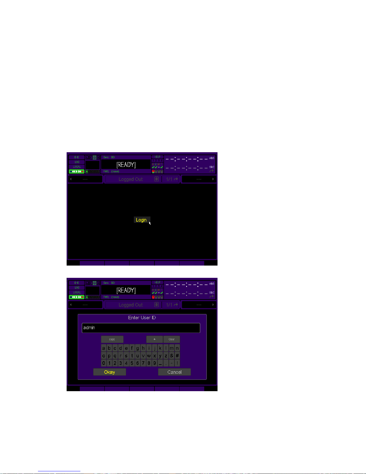
Account Management
Account management is available only via the ACCOUNT QShell (command line) utilit y. T he ACCOUNT command
may be used to LIST users, ADD new accounts, DELETE existing accounts, ENABLE account, DISABLE account,
IMPORT accounts from an existing “users” file, and turn ON|OFF the security system. For usage details for the
Account command, refer to the “QShell Command Reference Manual”.
Note: The system will prevent you from activating system (account) security if an Admin user has not been defined.
Account security may be enabled/disabled only using an ADMIN level user account.
Login from the front-panel GUI
With System Security active, the operator must login to gain access to the front panel GUI. The steps required to
login are graphically depicted below.
1. Place the pointer on “Login” button, located in the center of the screen, and press the center touchpad button.
2. Enter the User name in the dialog window provided. Click on Okay to continue to the next step.
3. Enter the password for the user account specified in the previous step. Click on Okay to complete the login
operation.
QuVIS Acuity™ Page 49 QSR Version 3.3

The Login indicator, the letter “L” enclosed within a box, is now active on the GU Dashboard to visually indicate
that someone is logged in. If you click on the indicator, a dialog window will be displayed showing who is
currently logged in (from the GUI) and their assigned permission level or account type.
QuVIS Acuity™ Page 50 QSR Version 3.3

Image Processing
The QuVIS Acuity supports two image encoding (compression) methods for real-time image recording and
playback: QPE (Quality Priority Encoding) and DCI JPEG2000. QPE is the native image encoding method used by
the Acuity.
NOTICE! DCI JPEG2000 playback support does require a specific hardware configuration (VSP version 9
required). DCI JPEG2000 real-time record also requires a specific hardware configuration (VSP version 9) and the
optional 2K DCI JPEG2000 Record Module.
QPE Real-time Image Encoding (Record)
QPE is a highly efficient image encoding method that has been utilized and endorsed for its superior image quality
by leading imaging industries including image acquisition and analysis, television production, film production, 3D
production and digital cinema production.
QPE is a QuVIS patented visually lossless wavelet-based image encoding method. QPE assigns the highest priority
to capturing all the information present in the incoming image so that statistical guarantees can be made for the
resulting image quality.
The desired QPE image quality is determined by the user-selectable Signal-to-Noise Ratio (SNR) value, specified in
dBs. The higher the SNR value the higher the image quality. Source image quality is important, as QPE will not
improve the quality of the source. It is possible that if the source image quality is poor and the QPE SNR value is
set higher than the source, unnecessary noise may be added to the encoded image thereby compromising
encoding efficiency.
QPE samples the entire image thereby eliminating block artifacts typically found in DCT encoding methods. QPE is
generationally stable and is an ideal encoding image format for content productio n an d post-production workflows.
DCI JPEG2000 Real-time Image Encoding (Record - Optional)
Real-time DCI JPEG2000 Image Encoding for Digital Cinema 2K formats is available as an optional processing
module for the Acuity. DCI JPEG2000 is the image-encoding standard selected by the Digital Cinem a industry.
Like QPE, JPEG2000 is a wavelet-based image encoding method. Image encoding with JPEG2000 typicall y takes
one of two forms: Fixed Bit Rate (FBR) encoding and Variable Bit Rate (VBR) encoding. The form currently
supported by the Acuity is VBR with a selectable quality (SNR) setting.
Note: To support real-time 2K DCI JPEG2000 Record, the QuVIS Acuity must be configured with a version 9 VSP
(Video Signal Processor) and the optional 2K DCI JPEG2000 Record Module must be licensed and installed.
QPE Image Decoding (Play)
The QuVIS Acuity base configuration supports real-time playback of QPE media files or clips. Playback support of
QPE media files includes: collapsed (interleaved video and audio tracks) clips, expanded (separate files for video
and audio essence) clips, Digital Cinema Composition Playlists (CPL) from QuVIS Digital Cinema Packages
(QDCP), script files (QScript), Virtual Tapes (VTP), and VTP timeline files (.tl).
JPEG2000 Image Decoding (Play)
The QuVIS Acuity base configuration (with VSP 9) supports real-time playback of DCI JPEG2000 media files.
Playback support of JPEG2000 media files includes: collapsed (interleaved video and audio tracks) clips, expanded
(separate files for video and audio essence) clips, Digital Cinema Composition Playlists (CPL) from Digital Cinema
Packages (DCP), script files (QScript), Virtual Tapes (VTP), and VTP timeline files (.tl).
The QuVIS Acuity provides native full-resolution playback support for 2K 12-bit 4:4:4:0 JPEG2000 image formats.
This includes full-container (2048x1080), scope, flat, scope-on-flat, and flat-on-scope image formats.
QuVIS Acuity™ Page 51 QSR Version 3.3

DCI JPEG2000 2K Playback Support
The QuVIS Acuity provides native full-resolution playback support for 2K 12-bit 4:4:4:0 JPEG2000 image formats.
This includes full-container (2048x1080) and partial container formats including: scope, flat, scope-on-fl at, and flaton-scope aspect ratios.
DCI JPEG2000 3D (2K) Playback Support
The QuVIS Acuity provides native playback of 3D (2K) Digital Cinema content. 3D Digital Cinema content is a 2K
image format. Both left eye and right eye image data (12-bit 4:4:4) is stored in a single file (per reel) but played as
two synchronized video streams.
Note: The QuVIS Acuity must be configured with a VSP card version 9 to be capable of supporting 3D JPEG2000
playback. A minimum software version is also required. If you have any questions, please contact QuVIS.
DCI JPEG2000 4K Playback Support
The QuVIS Acuity supports the ability to extract and playback (output) a 2K picture from a 4K composition. Due to
the architecture of a wavelet-encoded image, the 2K image is created by partially decoding the 4K image so that 2K
(2048x1080 or partial container) of image data is extracted and can be displayed. This 2K-from-4K capability allows
the Acuity to be used in combination with QuVIS QuStudio to master and preview a 4K Digital Cinema Composition
using the Virtual Tape Editor.
Encrypted Content Processing
The QuVIS Acuity natively supports Digital Cinema Content Encryption standards for both playback (content
decryption) and mastering (content encryption).
Encrypted Content Playback
Content encrypted using Digital Cinema encryption standards are protected from unauthorized use and require the
use of machine specific decryption keys delivered as Key Delivery Messages or KDMs (SMPTE 430-1: D-Cinema
Operations – Key Delivery Messages). The KDM files enables the Acuity to decrypt the encr ypted co ntent for
playback purposes.
Before a KDM file can be generated for a QuVIS Acuity, the server must be registered with the content
management system by providing the public key of the machine via a signed “X.509” device certificate file. The
signed device certificate file is generated by QuVIS and is stored in the /users directory on the system storage
volume.
The KDM file, issued by the content distribution authority, includes the necessary decryption information for the
target playback server to play the encrypted content.
IMPORTANT! The QuVIS Acuity is a content mastering server and is not intended to operate in insecure
environments without manual intervention. The QuVIS Acuity is capable of playing encrypted dig ital Cinema content
without Secure Link Encryption or Forensic Watermarking for content mastering and post-production preview
purposes. Secure Link Encryption and Forensic Watermarking is a Digital Cinema Exhibition requirement and does
not apply to the QuVIS Acuity when used in a secure mastering environment.
Mastering Encrypted Content
The QuVIS Acuity is capable of encrypting both DCI JPEG2000 and QPE Composition media files including
individual assets or entire tracks.
The Acuity does not provide content management services (e.g. KDM authoring) to create decryption keys for
content it encrypts. To facilitate key authoring, the Acuity must be registered with a content management system
(e.g. QuVIS QuStudio). The Acuity will use public key of the content management system to encrypt the selected
content. This structure allows the Acuity to encrypt the content and the content management system to generate
decryption keys in the form of KDM files for content encrypted using its public key. The public key of the content
management system is stored in the /users directory on the system storage volume in the form of a “*.pub.pem” file.
QuVIS Acuity™ Page 52 QSR Version 3.3

Forensic Watermarking Overview
QuVIS has partnered with Thomson to integrate their Forensic Watermarking technology, NexGuard, into QuVIS
Digital Cinema playback systems.
Image forensic watermarking is a licensed product feature and a purchasable option. To enable image
watermarking on the QuVIS Acuity (2K model) a valid license file is required and the feature must be activated
(turned on). For product licensing information contact QuVIS Sales at 800.554.8116 or sales@quvis.com
Technical Overview
Image Watermarking is the process by which forensic content tracking data is embedded in the picture during
playback that is stored in subsequent legitimate or stolen copies of the content. The forensic data embedded in the
picture is not visibly evident during playback so as not to detract from the quality of the content viewing experience.
The following outlines the operational implementation of image forensic watermarking:
• Image Watermarking on the QuVIS server platform does require that the server have a version 9.2.0 (or newer)
VIO circuit card. Questions related to hardware compatibility should be directed to QuVIS Customer Support.
• Image Watermarking will not be applied during playback of encrypted content unl ess a valid Watermarking
license is present and the feature is active (turned on).
• Image Watermarking is automatically disabled during playback of unencrypted content per Digital Cinema
exhibition guidelines.
• Image Watermarking is automatically disabled for encrypted content if the “WatermarkOff” keyword is present
in the <AnnotationText> element of the MPEG Interop KDM form currently in use. Provisions have been made
to migrate to the appropriate SMPTE KDM format (430-1) for disabling watermarking (forensic marking) once
the industry has adopted the SMPTE format as industry practice.
• Forensic Image Watermarking is operational even during playback speeds that are less than real-time (1x).
• The “LocationID” element, used to uniquely identify the pla yback source, is automatically assigned on a per
machine basis based upon implementation rules agreed upon between Thomson and QuVIS.
• The forensic data embedded in the displayed picture is outlined in the DCI Digital Cinema System Specification
document, section 9.4.6.1.
• Once the Forensic Watermarking feature has been licensed, the feature may be enabled/disable d via a
software switch only accessible to an Admin level user. This allows the feature to be properly setup. Once
Watermarking has been activated, turning it off will generate a security message in the logging system.
Subsequent playback of encrypted content with watermarking turned off or otherwise disabled will also
generate security messages to preserve the security audit trail.
• Image Forensic Watermarking is available only for 2K Digital Cinema formats. Image watermarking is
supported when a 4K package is played as a 2K extraction.
.
QuVIS Acuity™ Page 53 QSR Version 3.3

QuVIS Media File Types
Files that contain video and audio data are commonly referred to as clips or media files. There are several types of
media files that can be created and played by QuVIS video servers. Determining the type of media file to use is very
important. Each media file type is constructed differently in order to efficiently achieve the intended use of the
content (video and/or audio).
Aside from the video and audio format of the media file, there are three settings that serve as the foundation of a
media file. These settings are: QuVIS Media Format (QMF), Maximum Data Rate (MDR) and Clip Form.
QuVIS Media Format (QMF)
The QuVIS Media Format or QMF is a compatibility switch that identifies different file format standards used by
QuVIS video servers. There are currently three modes: QMF1, QMF2 and QMF3.
QMF1
– This QMF setting is used to identify collapsed clips (interleaved video and audio) that ma y be
played by the first generation QuVIS video servers, the QuBit, running a QuVIS Soft Release (QSR) of 1.x.
QMF1 content may be played and created by current products running QSR 2.x or 3.x releases. This
legacy clip file format has built-in controls that limit the options available for MDR, Metadata and Clip For m
in order to maintain playback compatibility with older 1.x QuBits.
QMF1 clip settings
• MDR = Maximum of 30MB/sec
• Metadata = Not supported
• Clip Form = Collapsed only (interleaved video and audio)
QMF2 – This QMF setting is used to identify media files that may only be created or played on QuVIS
video servers running a QSR release of 2.x or greater, including QSR 3.x. The QuVIS Acuity, Cinema
Player, Encore, Acuity and QuBit product line (ST, EL and DS) natively supports this QMF setting. QMF2
supports features that are tied to specific levels of hardware (circuit cards) that are not available for 1.x
version QuBits.
QMF2 clip settings
• MDR = 30 and 60MB/sec supported
• Metadata = supported
• Clip Form = Collapsed and expanded
QMF3
– This QMF setting is used to identify the JPEG2000 encoded Digital Cinema media files. QMF3 is
not a selectable setting but is automatically configured by selecting JPEG2000 Digital Cinema format files.
QMF3 Digital Cinema clip settings
• MDR = JPEG2000 250mb/sec
• Color Space = XYZ
• Clip Form = Collapsed and expanded
Maximum Data Rate (MDR)
MDR is used to set the upper data rate limit of a media file. These limits are set to correspond to the bandwidth
capabilities of the QuVIS video server that is recording the content or intended to play the content. A 1.x QuBit for
instance can only support a maximum date rate of 30MB/sec. Current products running QSR 2.x or greater support
a maximum data rate of 60MB/sec.
Aside from the product model and system software version, another important element that determines the ability to
record or play MDR 60 content is the number of drives that make up a QuVIS storage volume. A single-drive
volume can only support a maximum data rate of 30MB/sec. Multi-drive volumes (2 or more drives) will support
MDR 60 and is capable of sustaining data rates of 60MB/sec.
QuVIS Acuity™ Page 54 QSR Version 3.3

JPEG2000 Formats MDR Setting
The Maximum Data Rate (MDR) setting for JPEG2000 image formats are defined in Megabits per second or
Mbits/sec. This convention is used to reflect the terminology used by the Digital Cinema industry. Currently, only the
250Mbit/sec value is defined for Digital Cinema JPEG2000 formats. This value corresponds with the maximum data
rate (in megabits) defined by current Digital Cinema standards.
Clip Form
There are two primary clip form types: collapsed and expanded. The form of the media file dictates how the video
and audio assets of a media file are physically stored on disk. The other important element that is dictated by clip
form is whether or not the media file can be used in an editing environment.
Collapsed – Media files that are “collapsed” have both audio and video as sets interleaved together in a
single file. Collapsed media files are typically used to distribute a completed project as a single pl ayable
media object.
Expanded
media files that belong together share a common base name but have different file e xten s ions to indicate
the stored asset, video (.v) or audio (.a).
Expanded audio assets have additional flexibility that allows QuVIS video servers to store audio assets as
either a collection of all audio channels (cluster) or as individual audio tracks (discrete channels) stored in
separate files. An “audio cluster” is designated with a file extension of “.a” or “.wa: (QuVIS broadcast wave
format). “Audio tracks”, stored in separate files, are designated by a “.ann” file extension where “nn”
indicates the audio channel number the file was recorded on.
Expanded media files are structured to enable real-time editing using a QuVIS Virtual Tape editing object.
Virtual tapes enable QuVIS video servers to emulate a traditional linear tape editing process while
providing the additional flexibility of a digital workflow.
MXF (Digital Cinema)
stored on the QuVIS Acuity in a special expanded clip format. Composition image and audio files are
identified by their naming structure, which end in “_video.mxf” and “_audio.mxf”.
– Media files that are “expanded” use separate files to store video and audio assets. Expanded
– Media files that have been loaded from a Digital Cinema Package (DCP) are
Virtual Tapes
A QuVIS Virtual Tape (or VTP) emulates a traditional pre-striped videotape (a pre-formatt ed tape containing video
black and timecode) for editing in a post-production environment. Virtual tapes are editable media object that may
be created and edited only by a QuVIS mastering server (QuVIS Acuity, QuVIS Encore and QuBit ST). All current
QuVIS video servers (QSR 2.3 or greater) can be used to play virtual tapes. Offline clip tools, such as the Modclip
command, may be used to create other playable media files (including collapsed clips) using a VTP file (or timeline
file) as the source.
Virtual tapes let you record and edit content directly on the QuVIS mastering server as though it contains a fixedlength, striped videotape. Unlike traditional linear tapes, the recorded edits or media assets of a VTP are stored in
their entirety as clip files and the edit points are managed independently in the VT P container file.
Editing a VTP is a non-destructive process, meaning that when an edit is performed a new asset or clip is created
and does not overwrite existing data. Instead of overwriting any data on the VTP, a new set of pointers within the
VTP container file are created to point to the location of the new content.
Virtual tapes can be used for both QPE and JPEG2000 projects although these encoding formats cannot be
intermixed within the same VTP. Likewise, virtual tapes can be used with any supported image resolution and frame
rate provided that all of the content used matches the format settings of the VTP.
A VTP consists of several elements:
QuVIS Acuity™ Page 55 QSR Version 3.3

Virtual Tape Media File
that defines how the VTP was formatted. These properties include: video format, tape length, audio
properties (bit-depth and resolution), timecode and metadata. Additionally, this file maintains the list of
video and audio edits that have been performed.
Virtual Tape directory
parent directory, is used to store all of the physical video and audio edits (clips) that have been recorded.
The media file types that make up the individual edits are expanded clips.
Virtual Tape Timeline – A special timeline file, auto.tl, is stored in the virtual tape directory. This file is a
compiled version of the .vtp file that allows the system to edit or play the virtual tape in real-time. The
timeline file is automatically generated or updated by the system each time an edit is performed. This file
may not be copied or backed up. If the auto.tl file does not exist, the system will automatically regenerate
this file when the virtual tape is played or edited.
– This media file, designated with a “.vtp” file extension, maintains the properties
– A VTP directory having the same name as the .vtp file, located in the same
Show Playlist and Script files
Show Playlist and script files are special files that instruct the system how to play various Composition Playlist files
or segments of media files without interruption, as if they were one seamless production. Show Playlist and script
files are more than just a list of clips that are to be played in sequence. In addition to content sequencing Show
Playlist and scripts files can be used to interface with and control automation systems during playback.
A script file or digital cinema Composition Play List (CPL) file may be played from the primary GUI interface. Only
QuVIS script files may be played from the Cinema control interface, CineGUI. If a script file is selected for playback
from the Play Browser (1/5) menu page only play events are processed. Non-play script events are only processed
for playback if the script file is played via the CineGUI interface. The CineGUI interface may be accessed from the
Setup Config menu page.
IMPORTANT! Show Playlist or script files may not be placed under remote serial control for editing or playback.
Digital Cinema Packages
While the QuVIS Acuity is not intended to be used in insecure public exhibition environments it is necessary for
mastering purposes to support the loading and playback of Digital Cinema Packages (DCP). The QuVIS Acuit y
supports two types of Digital Cinema Packages: JPEG2000 and QPE.
The JPEG2000 form of a Digital Cinema Package is generically referred to as a “DCP”. JPEG2000 DCPs are
interoperable (can be loaded and played) by any industry-compliant Digital Cinema playback server.
The QPE form of a Digital Cinema Package is referred to as a QPE Digital Cinema Package or “QDCP”. QDCPs
are a proprietary form of Digital Cinema Package used to package and dist ribute QPE-encoded compositions and
are only supported by QuVIS servers.
Digital Cinema Package Ingest
Digital Cinema Package (DCP) ingest (loading) is currently a network data transfer operation facilitated primarily by
the PC utility, QuVIS QuLoad™. A Gigabit Ethernet connection between the PC (running QuLoad) and the QuVIS
Acuity is recommended to reduce load times.
For more information on the availability of the QuVIS QuLoad utility, contact QuVIS Customer Support at
support@quvis.com
.
QuVIS Acuity™ Page 56 QSR Version 3.3

QuVIS Image Format Files
QuVIS uses “format files” to store all of the system settings directly related to a particular video format. This
includes picture size, frame rate, display rate, etc. Format files describe to the QuVIS server how its hardware must
be setup in order to record or play a particular signal type. The format information is stored with the media file so
the server may quickly load the appropriate format file and prepares the system for playback.
Format files makes it easy to define a particular mode of operation without requiring the operator to set each setting
independently. QuVIS video servers are more flexible than most video recorders allowing the user to create content
for a wide variety of standard and custom display applications. Using form at files enables QuVIS to quickly add
additional image format support to meet emerging new standards or custom modes based upon customer
requirements.
There are three basic types of image format files: Windowed, Standard and Custom.
Windowed image formats
A windowed format is a special format designed to playback an unusual video sign al – one where the
image size is smaller than the format of the video standard used to deliver it. Early Digital Cinema (some
still exist) video projectors were unable to display the entire frame of an HD image. Windo wed formats
enabled the exact size of the picture the projector could accept (1280x1024) to be delivered via a standard
HD-SDI video interface. You might think of this format as a form of letterbox display. In the projector the
excess picture area is cropped so that the viewer see a full screen image.
Windowed image formats are notated with the letter “w” in the first part of the format file name.
Example: hd2w_1280x1026sf23.98
Video 4:2:2, 4:4:4:0 and 4:4:4:4 image formats
Standard or video image formats are those that strictly adhere to the published standards for a particular
format and frame rate. This includes Standard Definition (SD), High Definition (HD) and dual-link HD-SDI
(SMPTE 372M) video formats.
Use of 4:4:4:4 image formats are required when recording 3D QPE content.
Digital Cinema 2K and 4K (12-bit, 4:4:4:0) image formats
Digital Cinema formats use DCI JPEG2000 image encoding, which is reflected in the file name for these
formats.
Example: jp2k_2048x1080sF24
Example (DCI 3D): jp3d_2048x1080sF24
Custom image formats
QuVIS video servers support a variety of standard and custom graphics (VESA) video formats. These
image formats are typically Analog only formats meaning that may only be output via the servers Analog
Component Output (ACO).
QuVIS Acuity™ Page 57 QSR Version 3.3

QuVIS Acuity and Digital Cinema Content Mastering
QuVIS provides a complete end-to-end solution for the mastering of a DCI JPEG2000 Digital Cinema Package
(DCP) as well as QPE DCPs (QDCP). JPEG2000 Digital Cinema Packages authored using the QuVIS toolset are
interoperable with all industry compliant Digital Cinema playback servers employed for theatric al e xhibition
(playback) of Digital Cinema content. QPE Digital Cinema Packages (QDCP) are proprietar y and may only be
loaded and played on QuVIS serves (e.g. QuVIS Cinema Player).
In order to facilitate varying file-based and real-time workflow requirements the QuVIS DCP Mastering solution
utilizes a combination of PC-based software tools, QuVIS QuStudio, and real-time mastering hardware availabl e in
the QuVIS Acuity.
QuVIS QuStudio is a computer software application that provides many core functions including:
JPEG2000 image encoding (file-based workflow)
QuStudio provides the commercially licensed KAKADU software engine for encoding Image DCDM (Digital
Cinema Distribution Master) files to the Digital Cinema JPEG2000 image format.
DCP Packaging
QuStudio is used to package completed Digital Cinema Compositions into Digital Cinema Packages
(DCPs) once the project has been assembled, previewed and finalized on a QuVIS Acuity.
Key Management
QuStudio provides key management tools for encrypted compositions.
The QuVIS Acuity mastering server can be used to record Digital Cinema source content in real-time and apply
JPEG2000 image encoding as the input video stream is being recorded. The QuVIS Acuity also combines powerful
composition timeline assembly and editing tools with the ability to preview a composition in its entirety before it is
encrypted and finalized (i.e. packaged).
The QuVIS Virtual Tape (VTP) structure is used to assemble the DCP project timeline. This includes definin g the
order of the video, audio and subtitle track files and performing any necessary alignment changes to ensure that the
entire presentation is accurately timed and assembled. The Acuity’s VTP Editor provides a graphical Non-Linear
Editor (NLE) interface for editing the timeline of the DCP project.
Editing a VTP is a non-destructive process, meaning that when an edit is performed on either the VTP video or
audio track the timeline is updated with a new source track file pointer and does not physically overwrite the existing
edit. The VTP Editor provides a session-based ten-layer Undo/Redo mechanism that allows any timeline change to
be easily backed out or reapplied.
The Acuity’s VTR transport buttons and Jog/Shuttle wheel provide real-time playback (QC) of the entire VTP
timeline. This allows the operator to see (video) and hear (audio) the project timeline as changes (i.e. inserting
replacement tracks or segment overlays) are being made. In addition, subtitle file (not spot) placement can be
viewed with fade up/down rendering during playback and jog/shuttle control.
The DCP project timeline does not need to be assembled in one session. In fact portions of the project can be
processed at different times. This can be useful if the project assets (source image or audio files) are not ready at
the same time or if changes need to be made due midstream.
QuVIS Acuity™ Page 58 QSR Version 3.3

DCP Mastering – File-based Workflow Overview
QuVIS QuStudio provides the tool set necessary to encode or compress source image files that meet DCDM
(Digital Cinema Distribution Master) image specifications (16-bit Uncompressed T I FF, CAP XYZ colorspace) to the
JPEG2000 Digital Cinema standard. Encoded JPEG2000 image and Broadcast Wave audio files are then
transferred to a QuVIS Acuity where the DCP Composition timeline is assembled, edited, previewed and encr ypted
(optional). The DCP Composition is then transferred back to QuStudio where all of the assets are packaged and the
DCP is finalized and prepared for distribution. Encrypted content is registered with QuStudio for KDM (Key Delivery
Message) management.
DCP Mastering – Real-time Workflow Overview
The role of the Acuity in the DCP Mastering process varies depending upon the type of DCP Mastering workflow is
employed. If DCP source content can be played as a real-time video stream then the Acuity can be configured to
record that source and perform JPEG2000 image compression (encoding) real-time.
DCP Composition image and audio track assets can be recorded to the Acuity in a couple of ways including as
individual clips that can later be imported into a VTP (DCP) timeline or can be recorded directly into a QuVIS Virtual
Tape. Using the Virtual Tape Editor all of the assets can be edited, previewed and encrypted before the
Composition is finalized and packaged into a DCP.
QuVIS TitleMaster and Output Colorspace Conversion options can be employed to allow preview Subtitle track
assets on a wide variety of display devices including broadcast and production monitors.
QPE content production is popular and the same constructs and workflows that are used to package and distribute
JPEG2000 Digital Cinema content can be used to create QPE Digital Cinema Packages or QDCP. QDCP
packages are only support by QuVIS servers (currently only QuVIS Acuity and QuVIS Cinema Player).
QuVIS Acuity™ Page 59 QSR Version 3.3

Factors that affect picture quality when Recording
QuVIS video servers, including the QuVIS Acuity, have several settings that affect picture quality in different ways.
These can be categorized into two broad groups: those that affect p i ctu re q u ality directly (such as the SNR
control) and those that limit the picture quality possible (controls related to data rate management, which may in
turn limit picture quality).
Following are the items that affect recorded picture quality.
External Factors
Source Material
Image quality cannot be improved beyond that of the source material. The motion content, clarity and grain of the
source material will have some affect on the data rate of the recorded footage.
Signal Chain
Image processing components (noise/grain reducers, VDAs, etc) in the signal chain itself can degrade picture
quality.
Internal Factors
1.
Image Quality (Record Video menu page)
This control has the greatest direct affect on picture quality.
Note: Using a high SNR with a low MDR can force a situation where the failsafe is turning on too often. It’s
best to match the SNR setting to the source material, or set it only slightly above the SNR of the source
material, to avoid the data rate reaching the MDR setting.
2. Maximum Data Rate (Record Video menu page)
MDR can have a moderate to more extreme effect on picture quality, based on whether it is set correctly or
incorrectly for the source material and SNR. Set correctly, it will monitor and gently soften image quality only as
needed for extreme peaks in the data rate. If set incorrectly this setting can cause the system to constantly turn
on the data rate failsafe which can artificially lower image quality.
Note: The data rate failsafe mechanism lowers image quality when the data rate exceeds the MDR setting.
Using a high SNR and a low MDR can force a situation where the failsafe is turning on too often. It’s best to
match the SNR setting to the source material, or set it only slightly above the SNR of the source material.
3. QuVIS Media Format (Record Video menu page)
QMF selects between legacy-format clips and new clip formats with three data rate cap options: MDR30,
MDR60 and 250Mbit/sec (JPEG2000 formats only).
4. Destination volume capacity (Record Video menu page)
The destination volume may contain one to four hard disk drives. A one-disk volume cannot receive data as
fast as a volume with two or more drives. Recording 60p or dual-link HD-SDI content to a single-drive volume is
not recommended as the system may find it necessary to soften the picture quality if the peak data rate
exceeds the performance capabilities of the single hard drive.
QuVIS Acuity™ Page 60 QSR Version 3.3

Factors that affect picture quality during playback
Internal Settings
QuVIS video servers, including the QuVIS Acuity, have several settings that affect the playback picture quality in
different ways. You will want to know about these to ensure the QuVIS Acuity is always set up for the highest
quality output. Following are the software-controllable items that affect playback picture quality.
1. Bit Depth Compatibility (Play Video)
When playing content and recording it on another VTR, you may need to use the Bit Depth setting to match the
bit depth of Acuity’s output signal more closely to that of the capability of the destination VTR. When the output
is not rounded down in this manner, the receiving VTR’s circuitry may be unable to handle the excess data and
produce lower-quality recorded images as a result. Our recommendations for dubbing among common
equipment are below.
Format Acuity Bit Depth Output
HDCam 8 bit
D-5 9 bit
HDCam SRW 10 bit
10 bit SMPTE
compliant
Uncompressed HD 10-bit
2. Dither (Play Video)
When turned ON, Dither inserts electronically-generated noise into the picture. This may be useful for some
displays where it may produce a sharper-looking image. It is not recommended for production work or output to
plasma monitors, projectors or VTR’s (the added noise can be misinterpreted by their circuitry and cause a
degraded image). By default, Dither is turned off.
3. Analog Colorspace (Play Video)
This control adjusts color for your display device. If you connected the QuVIS Acuity to a monitor, projector or
VTR with a confidence monitor, and the output is excessively green or magenta-tinted, the Acuit y may be
outputting the wrong colorspace. Use this control to change the output colorspace.
4. Genlock (Play Video)
When the QuVIS Acuity plays back content, it can “reference” its video output signal either to a master timing
source or its own internal clock. The internal clock is commonly used in situations where the QuVIS Acuity is
simply playing back content for a trade show, digital cinema, or boardroom presentation, and the display devic e
is the only other equipment connected to the Acuity.
10-bit
QuVIS Acuity™ Page 61 QSR Version 3.3

External Factors
1.
Display device signal processing values
Due to differences in digital signal handling, display devices vary in their ability to reproduce a usable picture.
Digital projectors tend to display every flaw in a video signal. The same video signal that looks wonderful on
your office CRT monitor may be terrible on a digital projector. High-end projectors show the signal with much
greater accuracy than most monitors do.
However, even the digital circuitry in a brand name projector is not always above suspicion. The digital signa l
path through the projector can degrade the image, and the change in quality may range from unnoticeable to
unusable. This varies not only from one brand to another, but also from one product line to another in the same
brand (sometimes engineering teams work as discrete entities when designing product).
If you are having unexpected picture quality issues, first verify that you are viewing the materia l in the sa me
manner (i.e., on the same make and model) that you previously used. If it is different, expect some quality
differences. After that, the best solution is to check the settings for the display devices, and check the other
inputs to see if a better quality picture can be obtained by running a signal into it via a different input (i.e., using
HD via RGB rather than SDI).
2. Cable quality and cable length
The quality of your cable makes a big difference. Cables of the same length but from different manufactures
will exhibit different performance characteristics. Where possible, QuVIS recommends you use Belden 1 694A
“Brilliance” cable for serial video applications.
Remember that even quality cabling is subject to principles of physics (attenuation of the carrier signal due to
distance, connections, and patching equipment). For all cables, long cable runs will weaken high-frequency
signals, and unshielded electrical sources (like power cables place d alongside video cable) can definitely
interfere with the signal.
Video output signals can travel anywhere from 25 feet (7.6m) to 335 (102m) depending on the quality rating of
the cable used. If you need a longer run than your cable supports, you will need to use the proper distribution
amplifier to boost/equalize the signal.
3. Ambient light and screen framing
The amount of ambient light in a room has a direct bearing on the depth and clarity of the images you see. T his
is the reason movie theatres are nearly black inside. The more you can control the light levels in the room, the
better the image.
In addition, many projection screens are framed with a wide black frame. This enhances the appearance of
brightness and clarity to the eye.
QuVIS Acuity™ Page 62 QSR Version 3.3
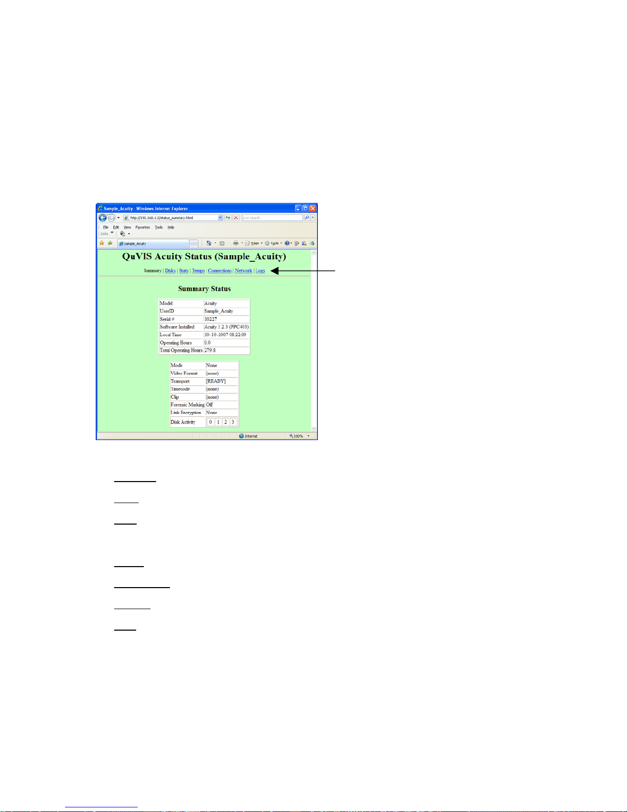
Server Status Web Page
The QuVIS Acuity is configured with an internal web server that allows an operator to view a summary of system
information from a set of server web pages.
To view the server status web pages, enter the server’s IP address in Address bar of your web browser.
Note: The information on the Status web page is not automatically updated after the web page is loaded. To update
the information on the web page use the web browser’s Refresh option (e.g. F5 function key).
Status web page links
There are seven categories of status information that can be viewed from the server’s status webpage:
Summary
Disks – displays a list of mounted storage volumes and their usage properties.
Stats
log. The same information can be viewed via command line (serial or Telnet session) by issuing the “Log stats”
command.
Temps – displays the current values of the internal temperature sensors.
Connections – displays local and remote-based (network) connections to the Acuity.
Network – displays a summary list of network settings including network address information and link status.
Logs
– displays general server information and its current operational status.
– displays a summary of the system Log including statistics on the number of messages recorde d in the
– displays unread messages stored in the system Log.
QuVIS Acuity™ Page 63 QSR Version 3.3

Control Panel Overview
The QuVIS Acuity Control Panel provides the visual display and physical controls required for local operation. The
Control Panel consists of four (4) main elements:
• LCD menu display
• Transport controls
• Touchpad controls
• Soft Function buttons
The Control Panel is connected to the chassis using a locking hinge mechanism. This allows the Control Panel to
be removed from the chassis for secure transportation or service. The Control Panel position is fully adjustable
using the stabilizer arm and slide lock located on the right side underneath the control panel. Raising the Control
Panel exposes the internal media bays providing easy access to the internal disk storage.
LCD Menu Display
Transport controls
Soft Function buttons Touchpad
LCD menu display
The LCD screen is used to display the Graphical User Interface or GUI used to operate the QuVIS Acuity from the
front panel. The GUI is a collection of menu screens (pages), status indicators and controls that provide access to
the system settings and operational control over all front panel functions including Pla y, Record and file
management operations.
Transport controls
The Transport controls consist of a collection of VTR transport buttons, a shuttle ring and jog wheel.
VTR transport buttons
The VTR buttons are used to control the speed and direction of playback and record operations. These buttons
operate in a similar manner to those found on a traditional VTR machine.
QuVIS Acuity™ Page 64 QSR Version 3.3
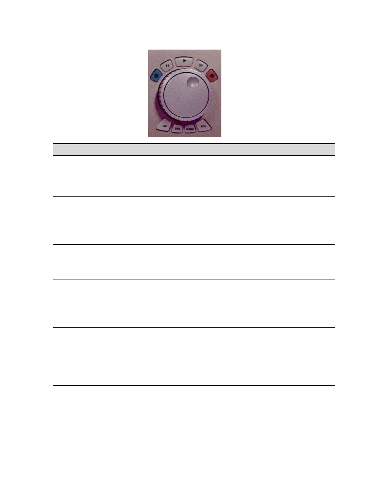
VTR buttons (above wheel) Description
STOP
REV
PLAY
FWD
REC
REC+PLAY
The STOP button is used to halt playback of a media file.
However, if the playstyle is set to Play jog/shuttle, the first press of the
STOP button will PAUSE playback. From there playback may be resumed
by pressing the PLAY button. To unload the clip while playback is paused,
press the STOP button.
The REV button is used to shuttle or frame-advance backwards through
the clip or media file currently under Jog/Shuttle control. Each additional
button press will increase playback speed in the reverse direction.
If the system is not playing or recording a clip, the REV button can be
used to cycle backwards through the GUI menu pages of the active menu
group.
The PLAY button is used to begin playback or resume playback of the
selected clip(s).
If the system is not playing or recording a clip, this button may be used as
a GUI shortcut to load the PLAY menu group.
The FWD button is used to shuttle or frame-advance forward through the
clip or media file currently under Jog/Shuttle control. Each additional
button press will increase playback speed in the forward direction.
If the system is not playing or recording a clip, the REV button can be
used to cycle backwards through the GUI menu pages of the active menu
group.
The REC button is used to load record settings and place the system in
the Record-ready state. To start recording, the REC+PLAY key
combination must be used.
If the system is not playing or recording a clip, this button may be used as
a GUI shortcut to load the RECORD menu group.
This button combination is used to start recording a clip from the front
panel.
QuVIS Acuity™ Page 65 QSR Version 3.3

VTR buttons (below wheel) Description
JOG
SHTL
SLOMO
GOTO
Jog/Shuttle Wheel
The Jog/Shuttle wheel is comprised of two separate controls that are controlled independent of each other. The
outer Shuttle ring is used for variable speed playback control. The inner Jog wheel is used for frame-by-frame
playback control. The JOG and SHTL buttons below the jog/shuttle wheel indicate what function is currently active.
The GUI Dashboard will display the active function as well as the speed and direction of playback.
The shuttle ring has a visible and physical center position indent or market to identify the pause or zero speed
playback position.
Jogging a clip
With the JOG button engaged (illuminated), turn the inner wheel in the desired direction (left = reverse,
right=forward).
Shuttling a clip
With the SHTL button engaged (illuminated), the outer ring in the desired direction from the center indent or position
marker (left = reverse, right = forward). As the shuttle ring is turned the speed of playback will increase in the
direction indicated. If the shuttle ring is turned back towards the center indent the speed of playback will decrease.
Touchpad
This button activates the inner Jog wheel for frame-by-frame playback
control. This function is only available if the playstyle is set to Play
jog/shuttle.
This button activates the outer Shuttle ring for variable speed playback
control. This function is only available if the playstyle is set to Play
jog/shuttle.
This button is used to activate Slow Motion (SLOMO) playback.
This button is used to jump to a specific timecode position within a clip.
The touchpad is a pressure sensitive surface used to control position of the GUI pointer. The printed surface of the
touchpad may be used to enter timecode values or alphanumeric text for certain operations. Text input control using
the touchpad is determined by the Text/TC Entry control on the Setup GUI (3/8) menu page.
To move the GUI pointer place the tip of your finger on the touchpad and move across the surface of the touchpad
in direction needed.
The buttons directly below the touchpad are used for item selection.
QuVIS Acuity™ Page 66 QSR Version 3.3

Touchpad buttons Description
Scroll (left rectangular button)
SELECT (middle rectangular
button)
CTRL Select (right rectangular
button)
Soft Function buttons
This button is used on the Play Browser menu page and any file browser
control to scroll the list of file and/or directories in the current path.
To scroll, press and hold
and move up or down to scroll this list in the direction indicated.
This button is used to select (or click) on the GUI item or control directly
underneath the GUI pointer. This is the equivalent to pressing the leftbutton of a traditional (right-handed) mouse on a computer.
SHIFT select – To select a range of files, place the pointer over the first
file, press and hold the center button and drag your finger in the direction
of the last file. Once the last file has been highlighted, release the center
button. All files between the first and last (inclusive) should now be
selected.
Note: You may also tap on touchpad to select if the Touchpad Tap
function (Setup GUI menu page) is enabled.
This button is used to select multiple non-contiguous files. This
functionality is the same as pressing the CTRL button on a keyboard and
selecting individual files from a PC file browser.
To select multiple files, place the pointer over each file and press the right
touchpad button. Repeat this for each file you would like to select. An
operation may be performed on all files selected (i.e. all selected files may
be deleted in a single operation).
this button. Place your finger on the touchpad
There are five soft function buttons located directly below the LCD display. The function of each button is defined on
the GUI directly above the buttons location. The global default assignment of each button is set to specific menu
page that can be loaded by simply pressing the corresponding soft button. The global setting for each button can be
assigned from the Setup GUI menu page using the Default Soft Buttons controls.
The types of action that can be globally assigned to Soft buttons (using the Setup GUI menu page) are limited to
loading a specific menu page. Navigation to any menu page can be assigned to any (or all) of the Soft buttons.
Custom soft button assignment will be saved, along with other GUI settings, when a configuration (Config) file is
QuVIS Acuity™ Page 67 QSR Version 3.3

created or updated. Config (configuration) files allow the operators to store different setting profiles based upon
project type or individual operator. See Setup Config menu page for config file options.
Change Soft Button Global Assignment
1. Load the Setup GUI menu page.
2. Click (center touch pad button or left mouse click) on the Soft button control in the DEFAULT SOFT BUTTONS
section.
3. F r om the menu page listing, select the menu page to be assigned to the soft button. Complete the selection by
pressing the center touch pad button (or left mouse click).
IMPORTANT! In order to retain Soft button assignments between sessions custom assignments must be saved in a
Configuration file.
Temporary Soft Button Assignments
The ability to temporarily assign individual menu page functions to soft buttons that temporarily override the gl obal
assignments, made on the Setup GUI menu page, is supported. To assign a specific menu page function (or
dashboard item – e.g. Read Log), place the cursor over the desired function, press the round touchpad button (so
that “Assign” is displayed in the lower right corner of the GUI) and press the soft button you want to assign the
function to.
IMPORTANT! Temporary soft button assignments for menu page functions are not savable and will be reset to their
global values (defined on Setup GUI menu page) when the server’s power is cycled.
QuVIS Acuity™ Page 68 QSR Version 3.3
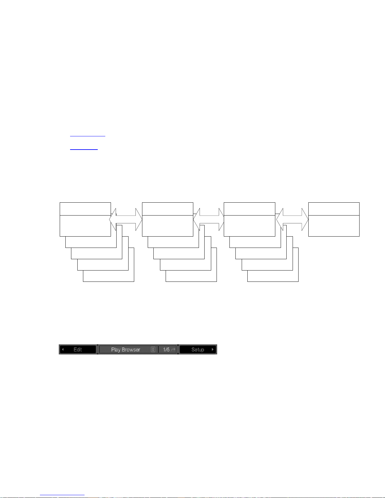
Introduction to the Graphical User Interface (GUI)
Local control of the QuVIS Acuity is performed from the front panel using the Graphical User Interface or GUI. The
GUI menu system is a collection of menu pages that provides a single interface to perform the basic operations
needed to play content, manage files, monitor status and change the configuration of the unit.
The GUI is automatically started once the unit has completed its power on cycle. Once the GUI is loaded on the
front panel display, all system services are available including local and remote control.
This section provides a description of the GUI menu system.
• GUI Overview
• Dashboard
GUI Overview
The Graphical User Interface features fast access to any of its screens or menu pages. Menu pages are collated
into logical groups, based on function, in order to place pages with similar control in close proximity of each other.
DASHBOARD
PLAY
PG 1/5
IMPORTANT: The exact number of menu groups and pages may change. The example given abov e is only an
illustration of the menu navigation and layout concept. The actual number of screens will vary.
Menu Groups
Menu groups are a collection of menu pages related to a specific functionality. The QuVIS Acuity currently has four
(4) primary menu groups: Play, Setup, Record and VTP.
“Navigating the GUI” means clicking the pointer over the left-pointing or right-pointing tab to move left or right to the
neighboring menu group. The tabs on each menu indicate the next screen in either direction. The menu cycles
around so that you never reach the end, you simple continue cycling around through the available menu groups.
Menu Pages
PLAY
PG 2/5
PLAY
PG 3/5
PLAY
PG 4/5
PLAY
PG 5/5
DASHBOARD
SETUP
PG 1/5
PLAY
PG 2/5
PLAY
PG 3/5
PLAY
PG 4/5
PLAY
PG 5/5
DASHBOARD
RECORD
PG 1/5
PLAY
PG 2/5
PLAY
PG 3/5
PLAY
PG 4/5
PLAY
PG 5/5
DASHBOARD
VTP
PG 1/2
Each menu group may contain multiple menu pages. Each menu page contains additional controls that modify
system settings related to that function or menu group.
To navigate through the different menu pages of a group, place the pointer over the menu page indicator and press
the center touchpad button to advance to the next page.
QuVIS Acuity™ Page 69 QSR Version 3.3
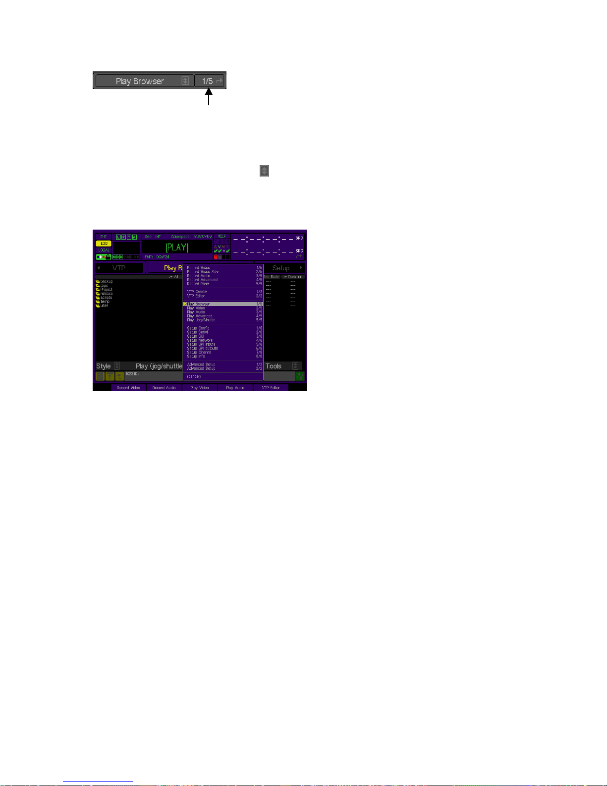
Menu page indicator
Menu List Navigation
The GUI provides a menu list in order to provide fast access to any menu page. The Menu list may be opened by
placing the pointer over the arrow control (
pressing the center touchpad button.
Once the list is displayed, place the pointer over the desired menu page and press the middle touchpad button to
select.
)to right of the name of the current menu page (center tab) and
QuVIS Acuity™ Page 70 QSR Version 3.3
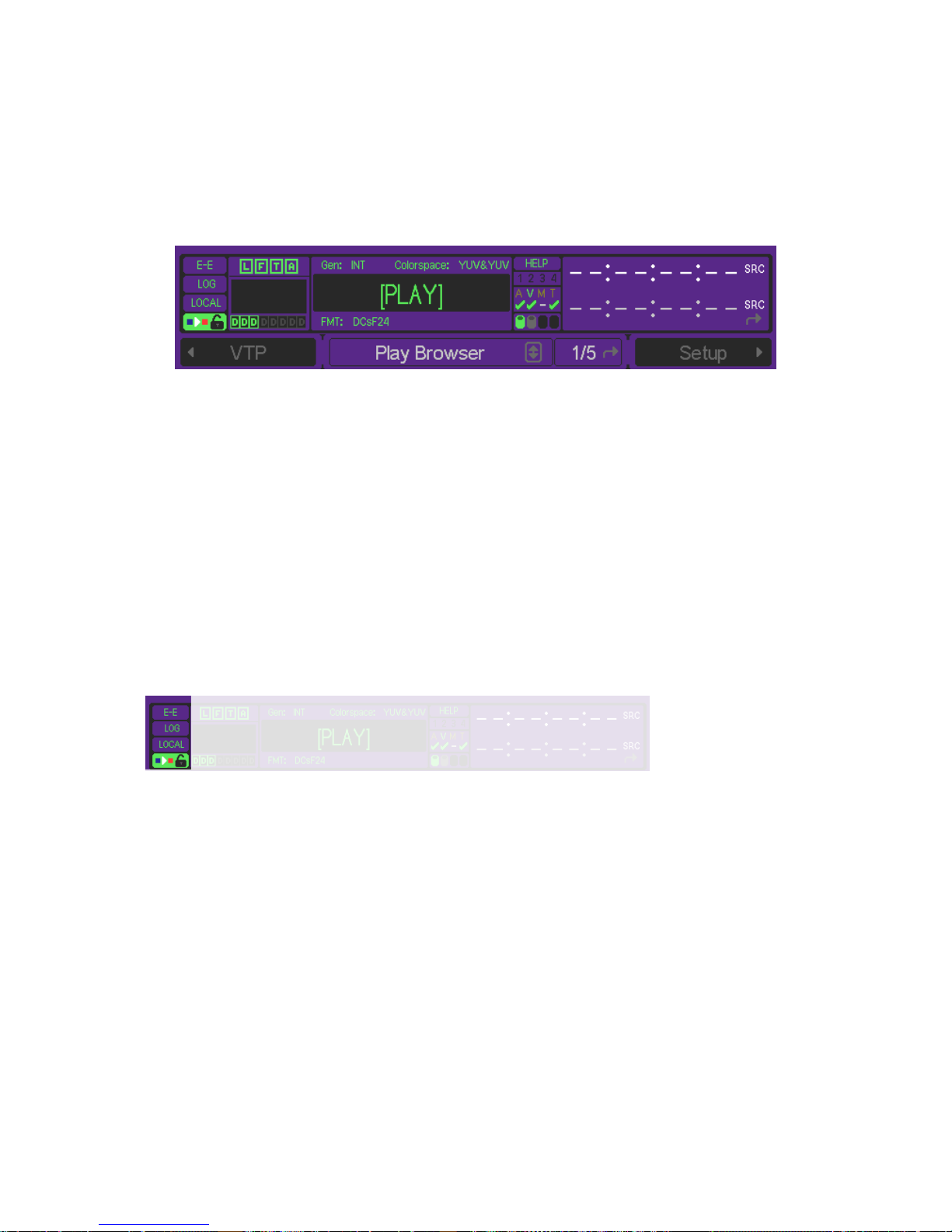
Dashboard
The most important element of the GUI is the dashboard; located in the upper quarter of the display the dashboard
includes a collection of system indicators and controls to provide instant feedback about the current settings and
operational status of the machine. The dashboard is always visible.
About Indicators and Controls on the Dashboard
Indicators serve a single function: they show status. For example, the four hard drive indicators (one indicator per
SCSI channel) show three states: inactive (dim), active and reading data (green), active and writing data (red).
Controls serve two functions: like indicators, they show status; like buttons, they allow you to make certain
functions. Several controls reside on the dashboard (special indicators that can be clicked on to change their
displays, or bring up a submenu). To help you distinguish between indicators and controls, when the pointer hovers
over an adjustable control, it will appear as a hand. Otherwise, it will appear as an arrow. Nothing in the dashboard
can affect the system settings adversely, so feel free to try each control to learn its function.
Dashboard sections
Status Section
E-E button
E-E engages an electronic pass-through of the selected video input, displaying the input signal inste ad of the
currently playing output signal. Click and hold to view the E-E signal.
LOG button
The log button is used to indicate if new messages have been added to the system log. If the log button illuminates,
pressing the log button will open the Log Viewer so that new messages may be reviewed from the front panel. T he
log will illuminate a different color depending upon the severity of the messages contained in the log.
Yellow = low priority notification or system message is contained in the log.
Red (solid) = an important notification or system warning is contained in the log.
Red (flashing) = critical system information is contained in the log.
QuVIS Acuity™ Page 71 QSR Version 3.3

LOCAL/REMOTE switch
This button engages remote control (remote control settings can be selected from the Setup Serial menu page).
Click to toggle local or remote control.
VTR Lockout switch
When on, this button locks out the VTR transport buttons, a useful feature when you want to work with the unit in an
uninterrupted manner. Note that this button is an advanced control whose access can be limited. If the button
cannot be selected, the Advanced Feature in GUI button on the Setup Config menu will unlock it.
User Login and Audio Section
User Login indicators
These indicators illuminate in order to show when a user or application has logged into the system. If the indicator is
lit, click on the indicator to display network connection information (including IP address and user).
[L] – Indicates a user has logged in from the GUI
[F] – Indicates a user has opened an FTP session
[T] – Indicates a user has opened a Telnet session
[A] – Indicates that an application has opened an API session (e.g. QuVIS QuDAC)
Audio Meters (16)
The audio meters display activity on the active audio channels. If the meter is darkened, then the audio channel has
not been turned on. The audio meter area of the dashboard may be clicked on (using the cursor arro w and the
center touchpad button) to open a large audio meter window and volume control interface. Individual audio channel
volume settings may be set from the large audio meter window.
Audio Channel Pair indicators
When illuminated, [A] or [D] indicates that the pair of channels above the indicator has turned on for recording. [A]
indicates Analog (only available for audio channel 1 and 2). [D] indic ates that the selected audio channels will
accept a Digital audio signal (AES/EBU).
If the indicator is green, the channels are ON for recording. If red, then they are ON but no signal is detected (no
signal is present or it has been since lost/disconnected).
Transport Section
SRC/GEN indicator
This indicator is used to display the status of the input source (SRC) signal while in record mode or the genlock
(GEN) source during playback. During playback, the indicator may change from green to red to indicate that
genlock has been lost (or lost and resumed).
If the source or reference has been regained this indicator may be reset, changed back to green, by placing the
cursor over the item and pressing the middle touchpad button.
Colorspace indicator
Displays the input (record) and output (play) colorspace as defined by the user-selectable Input (Record Video
menu page) and Output (Play Video menu page) colorspace settings.
QuVIS Acuity™ Page 72 QSR Version 3.3

FMT indicator
Displays the name of the current format for recording, or the format of the clip being played back. While in record
mode, if a valid input or video format is not detected, the format name will be displayed in red.
Transport Status
The “center” area of the dashboard is used to display current Transport and System status states. Special “states”
or modes will be shown in brackets as described below.
[PLAY] System is in a “play” state, but not yet playing clips (i.e., vmode p).
[RECORD] System is in a “record” state, but not yet recording (i.e., vmode r).
[QSDTI-OUT] System is in a “QSDTI” transfer out state (i.e., vmode o).
[READY] System is in neither a “play” nor “record” state (i.e., vmode n).
This may appear when performing diagnostics, for example.
BUSY System is busy switching modes, and is not ready for GUI control.
RECORDING System is recording content at 1x speed.
ARMED-TC System is paused in Record mode waiting for a timecode record trigger.
ARMED-SYS System is paused in Record mode waiting for a system time record
RECEIVING System is receiving content from a unit via Ethernet or QSDTI.
PLAYING System is playing content (at 1X speed).
LOOPING System is looping content (at 1X speed).
ARMED-TC System is paused in Play mode awaiting a time code play trigger.
ARMED-TOD System is paused in Play mode awaiting a system time play trigger.
SENDING System is sending content to another unit via Ethernet.
SHTL-PAUSED System is paused in Shuttle mode (Play).
SHTL +nX System is scanning Fwd (+) at “n” speed (n is a decimal).
SHTL -nX System is scanning Rev (-) at “n” speed (n is a decimal).
JOG System is in Jog mode.
COPYING System is currently performing a copy operation.
ARMED-SYS System is paused in Play mode awaiting a system play trigger.
BACKUP System is backing up footage to tape (reading from HDDs).
RESTORE System is restoring footage from tape (writing to HDDs).
FORMAT System is formatting a tape.
System Section
trigger.
Help button
Pressing this button will activate the on-line help system for the GUI. To distinguish between help mode and normal
operation, the HELP button will illuminate and the cursor changes to a question mark with an arrow.
To receive a description of a particular control or setting, place the help cursor over that item and press the center
touchpad button. A help dialog button will appear defining the selected item.
GPI Triggers (4)
If a General Purpose Interface (GPI) signal is either sent or received by the system, during the momentary contact
closure the GPI # will illuminate for the duration of the signal. GPI output triggers are shown in green and input
closures are shown in red.
AVMT Signal & REC/PLAY Status indicators
These indicators, when green, indicate a valid Audio, Video, Metadata or Timecode signal is detected. When the
indicate is white, it indicates no signal is present.
The row of indicators below AVMT provides an at-a-glance view of the status of audio, video, metadata, and
timecode for two operations: recording and playback. While the system is in record mode, the indicators show
whether any of these assets have been turned on for recording, and is ok to record (
QuVIS Acuity™ Page 73 QSR Version 3.3
), or is not present (x). A

plain dash (–) indicates the asset is not turned on for recording. During playback of a clip, these indic ators show the
presence (or absence) of these assets in the recorded clip.
SCSI Channel Activity indicators
These four indicators illuminate to show read (play) or write (record) activity on the four SCSI data channels. In
addition, once peripherals or drives are detected on a channel that channel ico n will become gray to indicate the
presence of a SCSI device.
Timecode Section
The QuVIS Acuity dashboard features dual time displays. The lower time display ma y be changed to show a
different timecode type by placing the cursor over the “timecode type” (located on the right) and pressing the center
touchpad button. The upper timecode indicator changes type according to the operation being performed and the
timecode settings for a given clip or media file.
ABS (absolute)
This timecode type starts counting from an absolute start time of 00:00:00:00.
FRM (frame)
This timecode type displays the current position in frame numbers.
INP (input)
Shows the current timecode value being monitored on the LTC input. In record mode, the upper display will autoswitch to INP to show incoming timecode.
SRC (source)
Each clip displays its original “as-recorded” timecode, matching source reels.
SYS (system)
Displays the current system time.
TCV (virtual)
This is the timecode that belongs to a QuVIS Virtual Tape or timeline file. When playing a virtual tape, the upper
display will auto-switch to TCV to show the timecode of the virtual clip.
Timecode display Notes
1. The dashboard timecode indicator will default to TCV (timecode virtual) when either a virtual tape or timelin e
with virtual time code is selected for playback.
2. The dashboard timecode indicator will follow the LTC outp ut (Play Video 2/ 5) setting when in pla y mode. If the
selected clip has source timecode (timecode that was recorded with the clip) AND th e LTC out control is set t o
“Original Source LTC”, then SRC time code will be displayed; otherwise ABS time code will be displayed.
QuVIS Acuity™ Page 74 QSR Version 3.3

CHAPTER 4 – FRONT PANEL GUI INTERFACE
Information in this chapter includes details of the front panel Graphical User Interface (GUI) including menu groups,
menu pages and system controls.
• PLAY menu group
• RECORD menu group
• SETUP menu group
• VTP menu group
• ADVANCED SETUP menu group
• CINEGUI Interface
QuVIS Acuity™ Page 75 QSR Version 3.1

PLAY menu group
The OUTPUT menu group is the collection of menu pages that are most commonly used to control playback
operations.
Menu pages covered in this section include:
• PLAY BROWSER (1/5) menu page
• PLAY VIDEO (2/5) menu page
• PLAY AUDIO (3/5) menu page
• PLAY ADVANCED (4/5) menu page
• PLAY JOG/SHUTTLE (5/5) menu page
QuVIS Acuity™ Page 76 QSR Version 3.3

PLAY BROWSER (1/5) menu page
This menu page is used to select media file(s) for playback operations as well as perform file management
operations. When the system is powered on, the Play Browser menu page is loaded as the default menu page.
This menu page has many of the same features you might expect on a standard file browser as well as some
unique features.
Play Browser
Controls
File Selection Window
Description
This menu panel provides a file browser to allow the operator to select a file or
files for play or to perform maintenance operations on. From here, the operator
can access all of the mounted volumes, directories and files on the system with
the exception of the “sys” directory, which is a protected area used only for
system files.
To select a single file use the center touchpad button or left mouse button if you
have a PS2 mouse connected.
To select multiple files, place the pointer over the first file and press and hold
the center button (left button on a PS2 mouse) and drag the cursor down the
last file you wish selected.
To select a directory place the pointer over the directory and press the right
touchpad button.
QuVIS Acuity™ Page 77 QSR Version 3.3

Play Browser
Controls
Description
Property Columns
These two columns display properties or attributes of the listed volume,
directories and files. The arrow (
may be changed (by clicking on them) to display a different property. These
columns are “sticky” and are saved along with other GUI settings when a
configuration file is created.
Property choices include:
– shows the date the file or directory was created.
Date
Time – shows the time of day or timestamp when the file or directory was
created.
– used to show the size of the listed file.
Size
Duration – used to show the duration of the listed clip or media file in ABS
timecode.
Format
– displays the format of the selected media file using the format “short-
name”.
– shows the QuVIS Media Format setting for the listed media files.
QMF
Rec Rate – shows the MDR (Maximum Data Rate) and Image Quality (SNR)
setting used when the content was created.
Avg Rate
Encrypt
that have been AES encryption for security purposes.
– displays the Average data Rate for the listed media files.
– displays the encryption status (locked/unlocked) for those media files
) is used to indicate that the property columns
Style popup and Play
button
QuVIS Acuity™ Page 78 QSR Version 3.3
These two controls work together. The Style popup is used to define how the
PLAY button beside it (and the VTR PLAY button) will work when selected. The
playstyle determines the behavior of local playback control of selected media
files. Available Playstyles include:
Play selected item
playback is completed the next selected file (if there is one) will begin playback.
Play jog/shuttle
Playback begins at 1x normal speed and direction. To jog or shuttle through the
clip use the Jog/Shuttle wheel to the right of the display.
Play loop/repeat
end of the clip has been reached during playback, it will immediately return to
the beginning of the clip and continue to play. To stop playback of a looping clip
you must press the STOP button on the front panel of the Acuity.
– Plays the selected media file(s) one time through. Once the
– Plays the selected media file with jog/shuttle control engaged.
– Plays the selected media file in a continuous loop. Once the

Play Browser
Controls
Description
Load remote control
virtual tapes) for remote RS-422 control. When the Acuity is placed under
remote control using the local/remote button (Dashboard), the Style control
automatically switches to this playstyle. Likewise, if this playstyle is selected, the
local/remote button in the dashboard is automatically toggled to REMOTE.
Pressing the VTR PLAY button or the GUI Load remote control button will
place the Acuity and the selected asset under remote control.
Note: Only one media file may be placed under remote control at any one time.
If remote access to multiple clips is required, then you may consider using the
Odetics protocol.
– This playstyle prepares the selected media file (including
File Operations buttons:
Info – Copy – Del Tools
Directory Size fuel
gauge
These buttons may be used to perform basic file and directory management
operations directly from the GUI. File management operation may only be
performed on files and directories that have been selected. Available
file/directory operations are as follows:
– This button is used to display the file/directory properties (size, date, etc)
Info
as well as selected media file asset attributes (video and audio formats and
settings) is a popup window.
Copy – This button is used to copy any files, including video and audio media
asset files, from one directory location to another. Files may even be copied to a
remote QuVIS server over Ethernet. Single and multiple copy operations are
supported.
Del
– Use this button to delete a selected file(s) or directory.
To delete a directory, the directory must first be empty of all files and
subdirectories. To select a directory for deletion, press the right touchpad button
once the cursor is directly over the directory.
Tools – This button displays a list of additional file management operations that
may be performed from the GUI. This includes:
Make directory – Create a new subdirectory. Directory names can be
up to 40 characters in length.
Rename – Rename a file or directory. File names can be up to 110
characters in length.
Set Comment – Create a text comment for the selected file.
VTP Clean – This utility is used to remove edits from a virtual tape that
point to assets that no longer exist. This enables a corrupted VTP,
where assets may have been deleted, to be updated to only include
edit that have physical assets assigned to them. This same operation
may be performed using the QShell VTPMerge command and the –
clean option.
VTP Editor – This option will load the select Virtual Tape (VTP) file into
the VTP Editor menu page for timeline editing or preview.
This display element, the divider bar between the file listing window and the
property columns, indicates how much of the directory is show and how much is
not visible. To display files/directory not currently visible, hold the left
QuVIS Acuity™ Page 79 QSR Version 3.3

Play Browser
Controls
Description
rectangular touchpad button down and drag your finger up/down on the
touchpad to scroll the file listing.
Quick-Access buttons
Current Path
Refresh View button
These three buttons change the current list to (from left to right): list volume
view, top-level view (root directory) of the current volume and display the parent
directory (up one level).
The current path including volume and directory is displayed here.
Click this button to refresh (update) the current directory/file listing. This may be
necessary if a file has been added or removed remotely (QShell user or FTP
transfer).
QuVIS Acuity™ Page 80 QSR Version 3.3

PLAY VIDEO (2/5) menu page
This menu page is used to configure the settings that define how the media will be controlled and lo ok during
playback.
Play Video Options Description
This button determines what form of LTC the Acuity sends on the LTC
output connector. Choices include:
LTC Out
Metadata Out
SDI Output Colorspace
No LTC output
Original Source LTC – Time code from the original recording
Absolute starting from 0 – Start playback from 00:00:00:00
This button determines what data is output in the Metadata portion of the
HD SDI signal that the Acuity sends out the HD SDI connector. Choices
include:
Original Source Metadata
the clip.
Same as LTC output
setting.
This control is used to select the video colorspace (RGB, YUV, or CAP
XYZ) output on Serial Digital Interface (SDI) during playback. This control
is only for controlling the output colorspace on the SDI output whereas the
“Ana Colospace” control is used to specify the output colorspace on the
Analog Component Output (ACO) connection (if present).
For playback operations, this control allows the operator to control the
output colorspace of a QPE or JPEG2000 clip (video media file)
regardless of what colorspace the clip was created with (i.e. XYZ, YUV or
RGB).
Colorspace choices for this control include YUV, RGB and CAP XYZ.
– No time code output
– Output the Metadata that was recorded with
– Outputs the same signal specified in the “LTC Out”
QuVIS Acuity™ Page 81 QSR Version 3.3
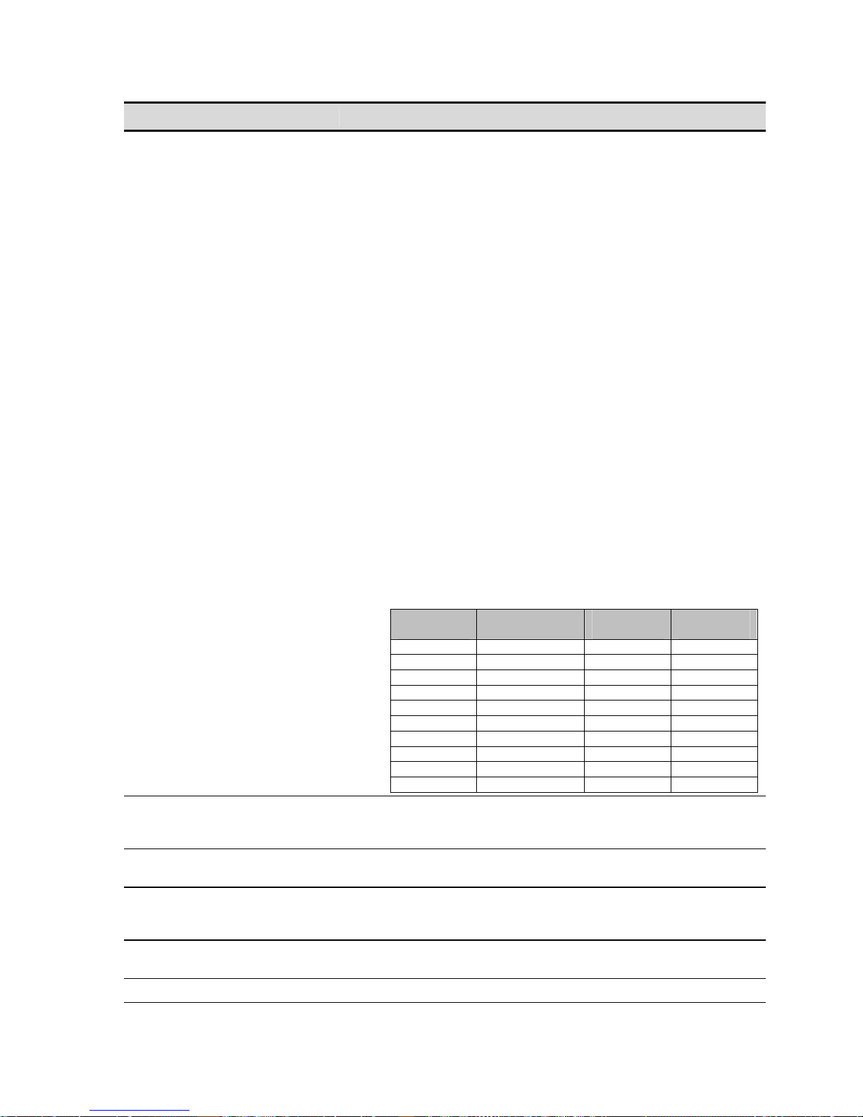
Play Video Options Description
Notes:
1. Due to hardware limitations, if playing co ntent on the Analog
Component Output (ACO) interface then the SDI Output
Colorspace control MUST be set to YUV in order to have a valid
output signal on the ACO.
2. Regardless of how a clip was recorded (XYZ, RGB or YUV), it
can still be output in any colorspace, provided you specified the
correct colorspace during record. QPE clips, when output as a
SDI video signal, do not automatically prefer a specific
colorspace but will play out according to the setting of this control
(SDI Output Colorspace).
3. JPEG2000 XYZ content can be converted to YUV or RGB (REC-
709 or P3) for playback purposes using this control.
4. YUV and RGB The Acuity currently only supports the REC-709
color profiles for the YUV and RGB colorspace.
5. As a summary, the following matrix outlines the Output
colorspace conversion capabilities of the QuVIS Acuity.
The supported XYZ colorspace is commonly referred to as the
“CAP XYZ” colorspace used in the Digital Cinema industry. Per
Digital Cinema requirements, DCI JPEG2000 content is not
stored in the CAP XYZ colorspace but rather is processed with
an Irreversible Color Transform (ICT) in order to store the data in
color-difference XYZ or “DCP XYZ” (QuVIS term) format. During
playback an inverse ICT is applied to the DCI JPEG2000 content
(DCP XYZ form) in order to transform the colorspace back to
CAP XYZ for exhibition.
Colorspace
YUV (709) QPE YUV (709) YUV (709)
YUV (709) QPE RGB (709) RGB (709)
YUV (709) JPEG2000 DCP CAP XYZ
RGB (709) QPE RGB (709) RGB (709)
RGB (709) QPE YUV (709) YUV (709)
RGB (709) JPEG2000 DCP XYZ CAP XYZ
CAP XYZ JPEG2000 DCP XYZ CAP XYZ
CAP XYZ JPEG2000 DCP XYZ P3 RGB (TI)
CAP XYZ QPE/JPEG2000 YUV (709) YUV (709)
CAP XYZ QPE/JPEG2000 RGB (709) RGB (709)
Genlock
Genlock Phase
(Genlock option required)
Bit Depth
Ana Colorspace (Analog
Colorspace)
Dither
Use to set the input source to which the Acuity will lock its output playback
signal. If the Acuity does not have the “Genlock hardware option” installed,
the only available option will be Internal.
This control is used to delay (phase in) the genlock signal (analog) to
compensate for signal variations.
This control is used to set the output signal to match a receiving device,
such as a VTR. This control only affects analog video output and does not
affect Serial Digital (SD and HD) outputs.
Use this control to change the output analog colorspace for SD/HD 4:2:2
QPE content. Choices include RGB or YUV.
Dither adds a degree of electronically-generated noise or grain to the
Input
Encoding Recorded
Colorspace
Output
Colorspace
QuVIS Acuity™ Page 82 QSR Version 3.3

Play Video Options Description
playback. This control affects all video outputs. Adding dither to the output
may yield a more pleasing playback image with some display devices. Not
recommended when editing or dubbing as the added noise can make for a
poorer signal.
Use this control to change the output sync signal type. Options include Bi-
Level (black burst), Tri-Level and Separate H & V.
Ana Sync (Analog Sync)
Last frame hold
Notes: Analog options (Ana Colorspace, Ana Sync) are only available if the Analog Component Output (ACO) card is
installed in the Acuity.
Note: Display devices may need a specific form of sync signal to show
image properly. The type of sync signal required is dependent upon the
specific display device being used.
Use this control to instruct the Acuity to hold the last frame of video when
the system has stopped playing.
QuVIS Acuity™ Page 83 QSR Version 3.3

PLAY AUDIO (3/5) menu page
This menu page is used to define the output audio settings. This includes the ability to route digital channels to the
one or both of the analog channels for easy confidence monitoring.
Play Audio Options Description
These two controls allow you to route any audio channel to either
analog/headphone channel. Routing to channel 1 is the same as the left
speaker of a stereo headphone as is routing to channel 2 is the same
as the right speaker of a stereo headphone.
Analog Mix Left & Right
Audio Meters
For example, channels 1, 3, 5 and 7 can be routed to analog left and
channels 2, 4, 6 and 8 can be routed to analog right so that all 8
channels may be heard as stereo output on the analog out pair or
headphone jack. Alternately, all channels may be routed to a single
analog channel for monitoring purposes.
This does not affect the output of each digital audio channel.
Use this button to display the enlarged set of audio meters and volume
controls also available by clicking on the dashboard audio meters. This
pop-up display allows the volume level of each individual audio channel,
analog or digital, to be set independently or universally using the
“Master” volume control. The volume settings are a system
Environment Variable setting and are saved when a new configuration
file is created.
Headphone Volume
QuVIS Acuity™ Page 84 QSR Version 3.3
Use this control to set the volume for the headphone jack beneath the
Acuity’s front bezel.

Master Volume
Master Frame Delay
Use this control to set the volume level for all audio channels.
This control is used to delay all audio channels by the specified number
of frames to compensate for any creation or equipment routing offsets.
QuVIS Acuity™ Page 85 QSR Version 3.3

PLAY ADVANCED (4/5) menu page
This advanced panel allows you to setup a single automated play event based on sev era l different “triggers”.
Play Advanced Options Description
This control defines the event that triggers the start of playback.
Auto-play start trigger
Start playing at
Auto-play end trigger
Choices include incoming LTC timecode or System Time (you can
check the current system time by clicking on the arrow button to the
right of the lower timecode display until it shows SYS).
Use this button to specify the system time or input timecode value
(LTC) at which the triggered playback should begin.
This is the event that triggers the end of playback. Choices include:
Disabled
is set to “Play selected item”, the selected clip or media file will play
until the end of the clip is reached. If the playstyle is set to “Play
loop/repeat” then the clip will continue to play until playback is
manually stopped.
To manually stop the triggered playback session, press the STOP
button on the front panel of the Acuity.
Elapsed Time
play session once the specified elapsed time, set the “Stop playing at”
button, has passed.
Timecode
playback once the LTC timecode value, set by the “Stop playing at”
button, has been received.
System Time
once the specified system time, set by the “Stop playing at” button, has
been reached.
Note: If the Playback End Trigger value (Elapsed Time, Timecode or
System Time) is a point in time that is longer than the runtime of the
selected clip, playback of the clip will stop before the End Trigger is
activated.
– Auto-play End Trigger is turned off. If the selected playstyle
– Enables the Acuity to automatically end the triggered
– Enables the Acuity to automatically end the triggered
– This end trigger is used to automatically stop playback
QuVIS Acuity™ Page 86 QSR Version 3.3

Used to specify the time value associated with the selected “End
Stop playing at
Trigger” method. Auto-play End Trigger must be enabled to set the
end time of the triggered play event.
How triggered playback works
1. From the Play Advanced menu page the start and stop (optional) trigger methods must first be defined using the
“”Auto-play start trigger” and “Auto-play stop trigger” controls. Secondly, the values that correspond to the start and
stop triggers must be defined using the “Start playing at” and “Stop playing at” controls.
2. Select a clip or playable media (Play Browser menu page) and then press PLAY to place the system into an
armed state, awaiting the start trigger event. When the start trigger point is reached, playback will begin. If a stop
trigger has been set, playback will stop once the end trigger value has occurred.
To cancel the armed-and-waiting process, press the STOP transport button the front of the Acuity, which will cancel
the process and clear the trigger events. As indicated, if the operation is canceled, the trigger events will be cleared
and must be reset manually if triggered playback is desired.
QuVIS Acuity™ Page 87 QSR Version 3.3
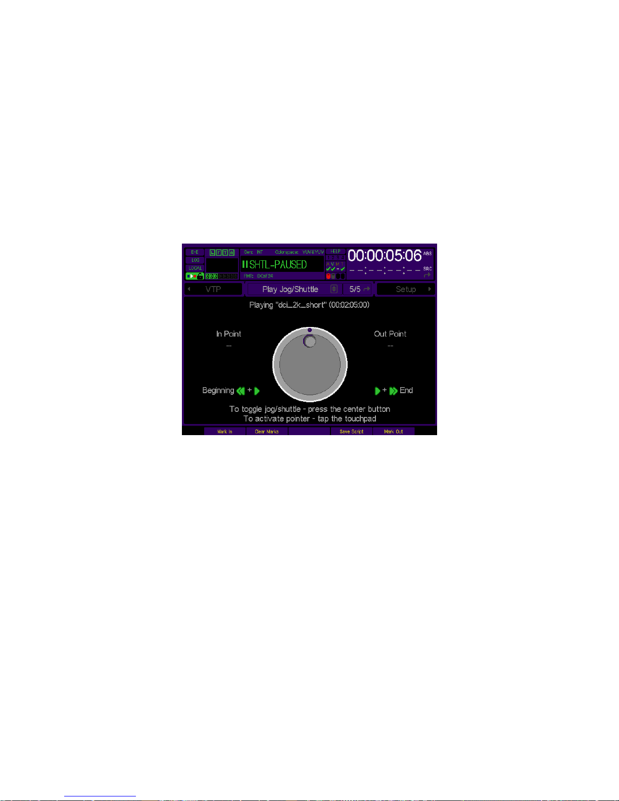
PLAY JOG/SHUTTLE (5/5) menu page
The Jog/Shuttle menu screen is automatically loaded when playback of a clip is initiated, if the playst yle is set to
Play jog/shuttle. During jog/shuttle playback, either the outer shuttle ring or the inner jog dial will appear highlighted,
indicating which function is active. The physical Jog/Shuttle wheel to the right of the displ ay performs primary
transport control of the Jog and Shuttle functions. The buttons labeled Jog and Shuttle directly be neath the physical
wheel are used to activate the appropriate control style. The active control style is indicated both on the GUI
Dashboard as well on the active button, which will illuminate.
The QuVIS Acuity does retain touchpad control functionality in order to maintain proper control of the Jog/Shuttle
functions remotely using the QuDAC remote control software. Likewise, the VTR Transport buttons (located above
the Jog/Shuttle wheel itself) may be used to adjust the speed of shuttle playback or frame-step through the clip
while under Jog control.
Operational Notes
1. Shuttle playback (at 1x speed) is the default control method when playback of a clip is started.
2. To change the Shuttle playback speed and direction of the clip, press the SHTL button (if it is not already selected)
to activate the outer ring of the Jog/Shuttle wheel.
Shuttle Forward
Turn the shuttle ring clockwise from the center indent to modify the speed of forward playback.
Shuttle Reverse
Turn the shuttle ring counter-clockwise from the center indent to modify the reverse playback speed.
Note: You may also modify the speed and direction of shuttle playback by pressing the FWD (fast forward) or REV
(reverse) button above the Jog/Shuttle wheel. Each time the button is pressed, the speed of playback will increase
in the direction indicated.
3. To step through the clip or media file frame-by-frame, press the JOG button (if it is not already selected) to active
the center jog dial.
Jog Forward
To advance through the clip frame-by-frame rotate the center dial clockwise using your finger.
Jog Reverse
To backup or transverse the clip frame-by-frame, rotate the center dial counter-clockwise using your finger.
QuVIS Acuity™ Page 88 QSR Version 3.3

Note: You may also use the VTR buttons (FWD or REV) located above the Jog/Shuttle wheel to frame-step through
the clip in the direction specified by the button press. Each time the button is pressed, the clip will be advanced to
the previous (REV) or next (FWD) frame.
4. Normal playback of a clip under Jog/Shuttle control may be resumed either by rotating the shuttle wheel to the right
of the center indent until the Dashboard displays “PLAYING” or by simply pressing the PLAY button directly above
the jog/shuttle wheel.
5. Playback of a clip under the Jog/Shuttle playstyle is similar to controlling playback of videotape. If the end of the clip
is reached the clip remains loaded waiting for additional transport instructions. To end playback of a clip under
jog/shuttle control, the STOP button must be pressed twice.
The first press of the STOP button will halt playback control of the clip and place it in a PAUSED state.
While in the PAUSED state, playback (shuttle) or frame-step (jog) control of the clip may resume by using the
appropriate controls (VTR transport buttons or Jog/Shuttle wheel) or the clip may be unloaded from jog/shuttle
control and playback halted by pressing the STOP again.
6. During playback of a clip under the Play jog/shuttle playstyle, the navig ation pointer is hidden in order to ensure
proper control of the virtual jog/shuttle wheel. To activate the pointer and navigate elsewhere within the GUI
(without existing jog/shuttle), tape the touchpad once. The pointer will appear and you may navigate other screens
(remember to return to PLAY 5/5 so that you can exit jog/shuttle playback afterward).
To restore jog/shuttle control after re-displaying the pointer, tap the touchpad again (while on the PLAY 5 /5 menu
page) to hide the pointer.
Note: Activating/deactivating the pointer will not work if the touchpad TAP function has been disabled on the
SETUP GUI menu screen (Setup menu page 3/8).
Clip-based Script Authoring
On the Play Jog/Shuttle menu page are four controls that can be used to create a mini-script (single play event
only) by marking an In Point and Out Point for a collapsed (interleaved audio and video) clip.
1. To set the In Point play (Shuttle or Jog) the current clip and stop on the desired frame (timecode position).
2. Press the Mark In soft button.
3. To set the Out Point, play (Shuttle or Jog) the current clip and stop on the desired frame (timecode position).
QuVIS Acuity™ Page 89 QSR Version 3.3

4. Press the Mark Out soft button.
5. To create a script with a single play event using the current clip and its marked In and Out points, press the
Save Script soft button. The script will be saved with a system-assigned name and will be stored in the
directory the current clip is stored.
6. To play the saved script, select it from the Play Browser menu page and press PLAY.
QuVIS Acuity™ Page 90 QSR Version 3.3

RECORD menu group
The RECORD menu group is the collection of menu pages that are used to configure the QuVIS Acuity to record
video, audio and metadata (including timecode) from an external source (Telecine, camer a, VTR, etc.).
Menu pages covered in this section include:
• RECORD VIDEO (1/5) menu page
• RECORD VIDEO ADV (2/5) menu page
• RECORD AUDIO (3/5) menu page
• RECORD ADVANCED (4/5) menu page
• RECORD PANEL (5/5) menu page
• RECORD PANEL (after recording a clip) menu page
•
2K DCI JPEG2000 Recording Overview
TIP: A message line is located at the bottom of each record setup menu page in order to provide visual
confirmation that the selected record settings are not in conflict with each other.
If the selected settings are compatible with the systems capabilities, the message will read “(OK to record)”.
If the selected settings are not compatible with dependent settings, the message will indicate that there is a
setup problem to be corrected. Additionally, the affected settings will be displayed in red text.
Keep in mind that if you only see one setting on a menu page that is listed in red, the other setting it conflicts with
may be on a different RECORD menu page.
QuVIS Acuity™ Page 91 QSR Version 3.3

RECORD VIDEO (1/5) menu page
This menu page is used to set the primary video and system settings to be used during a record operation.
Record Video Options Description
Image Format
Input Source
Image Quality
Click on this button to select an image format file that matches the
material you wish to record (a format file defines the height, width, and
frame rate of a recorded signal). The popup menu allows you to sort
the list of formats by type. More information can be found in the QuVIS
Image Format Files section.
Select the appropriate Input Source according to the input format.
Serial Digital Input (SDI)
Standard Definition or High Definition serial digital input signal.
Analog
– This input is used to record an Analog Component Video
signal (YUV/YprPb).
Set the Image Quality (SNR) setting for recorded material. The typical
setting used in a production environment ranges from 51 – 63dB. The
higher the number the higher the quality and larger the data set.
The Image Quality settings used to record DCI JPEG2000 content
(VSP version 9 hardware and JPEG2000 Real-time Record Module
required) are presented as a Low, Medium, or High value. These
three settings (used only for DCI JPEG2000 record setup) are roughly
equal to 48dB, 54dB, and 60dB respectively.
IMPORTANT! The image quality setting defines the minimum quality
level that will be preserved during the record process. There are two
aspects of image quality that must be considered when making the
value selection:
Source Image Quality
selected record setting the server will not enhance the source image
quality but may in fact be adding unnecessary data to the recorded
image stream.
Maximum Data Rate
high value there is a chance when recording a complex image
– This option is used to record either a
– If the source image quality is lower than
– If the selected Image Quality setting is set to
QuVIS Acuity™ Page 92 QSR Version 3.3

Record Video Options Description
sequence (e.g. busy crowd scene) that the Maximum Data Rat e setting
may trigger the server to invoke a record failsafe mechanism that will
temporarily reduce the image quality in order to prevent data clipping or
in extreme cases dropped frames.
The Colorspace control is used to define the colorspace of the source
input video stream. The Acuity has the ability to convert the native
colorspace of the input source to native colorspace of the record
format.
All QPE-encoded formats are stored in YUV. The source colorspace
can either be YUV or RGB. In the case that source content colorspace
is RGB, it must be specified so that the Acuity can properly convert it to
the stored colorspace. Separate Output Colorspace options are
available to change the colorspace during playback.
Colorspace
Destination
QuVIS Media Format
Maximum Data Rate
All JPEG2000-encoded formats are stored in XYZ. If the source content
colorspace is not CAP XYZ it can be automatically converted from YUV
(709) or RGB (709) real-time during record in order to comply with
Digital Cinema requirements. Separate Output Colorspace options
are available to change the colorspace during playback.
Note: If the source content colorspace is not XYZ, you must specify the
colorspace to ensure proper color-rotation during record.
IMPORTANT! JPEG2000 Real-time Record capability is a licensed
feature module and requires specific hardware components.
Select the destination (volume and directory) where recorded assets
will be stored. A volume, in QuVIS terminology, is a set of one (1) or
more hard drives that effectively serves as a single storage device.
Note: There may be limit to your ability to record high-quali ty, high
frame rate material depending upon the number of disks that make up
the destination volume. The minimum number of drives in a volume is
generally determined by the Maximum Data Rate setting. General
guidelines are as follows:
MDR30 = 2-drive volume
MDR60 = 2-drive volume
The QuVIS Media Format (QMF) is a compatibility switch that identifies
different QuVIS file format standards.
Select QMF1 if the recorded media file is expected to playback on a
version 1.x QuBit product. Select QMF2 if the recorded media file
needs to be backward compatible with the QuBit 2.x product line (QuBit
ST, EL and DS running QSR 2.3 or higher). QMF3 is the media format
used for DCI JPEG2000 content and is currently only supported on the
appropriately configured QuVIS Acuity.
For additional information, see the QuVIS Media Format (QMF) in
Chapter 3.
Note: Not all hardware configurations will support record or playback of
QMF1 and/or QMF3 content.
Maximum Data Rate (MDR) is used to set the upper data rate limit
when recording. Legacy 1.x QuBits (QMF1) only support an MDR of
30MB/sec. For additional information, see the Maximum Data Rate
(MDR) section in Chapter 3.
QuVIS Acuity™ Page 93 QSR Version 3.3

Record Video Options Description
Note: Additional consideration must be given to the number of drives
that make up the destination volume. A single-drive volume will not
support data rates that exceed 30MB/sec. Although it is permissible, it
is not recommended that you attempt to record to a single-drive volume
if the MDR setting is set to MDR60. This may result in undesirable
degradation of picture quality and may even result in some frames not
being recorded.
This selector allows you to chose the form of encoding used when
recording clips. Your choices include QPE (spatial) and ADR (spatial).
Both are a spatial form of encoding motion imagery (meaning they are
frame-based and yield fully-editable content).
QPE is the standard wavelet-base encoding method used by QuVIS
video server products. This setting is most often used under normal
motion-imaging recording conditions.
Encoding
JPEG2000 is the image encoding method required to author Digital
Cinema compatible content.
ADR is a special version of QPE that incorporates a low data-rate
quality safeguard designed for production applications. ADR boosts low
data rates by increasing the SNR to better preserve simple imagery,
which is ideal for test patterns or other low data-rate high quality
images.
QuVIS Acuity™ Page 94 QSR Version 3.3

RECORD VIDEO ADV (2/5) menu page
This menu page provides advanced settings that define what video assets are to be recorded and how the recorded
assets are to be structured in the resulting media file.
Record Video Adv Options Description
This control is used to select the form of the video assets as they are
recorded. Clips recorded in the QMF1 domain are always collapsed.
Clips recorded in the QMF2 domain may either be collapsed or
expanded.
Clip Form
Include metadata
Noise Coring
Collapsed
exist in an interleaved format within the clip file structure itself. All of the
recorded assets are stored in a single file.
Expanded
of distinct media files with a separate video track and some number of
audio tracks.
Metadata is ancillary data inserted in the serial digital data stream and
may or may not be present in serial digital recorded content. When
metadata is present, the metadata presence indicator will illuminate.
Turn this control on to record metadata from a serial digital input.
The QuVIS Acuity may be configured to record either standard
metadata (SMPTE RP-215) or IRIG timecode data.
Noise coring reduces low amplitude, high frequency signals. Dither,
film grain, and other sources of electronic “noise” are examples of what
can be reduced. The higher the setting, the more aggressively noise is
reduced, resulting in “cleaner” looking pictures and lower data rates.
As always, the results will vary for different types of content.
Off
Low
picture differences.
High
– This form setting means the audio and video image data
– This form setting indicates that the clip exists as a number
– This is the default setting.
– will reduce data rates by about 5% with virtually no visible
- will reduce data rates up to 15% with subtle visual loss.
QuVIS Acuity™ Page 95 QSR Version 3.3

Record Video Adv Options Description
Timecode
Drop Frame Mode
3D Format
Select which timecode input source should be used for recorded
timecode. Choices include the LTC input or the Internal timecode clock.
This control allows you to select either the default timecode type that is
built-in to the selected image format or override the default setting.
Choices include:
Format Default – the timecode type (drop or non-drop frame) is
determined by the selected image format and will change appropriately
when the image format is changed.
Non-drop
non-drop frame timecode (1/1000) regardless of the timecode type
defined by the selected image format.
Drop – this override setting will force the system to always record dropframe timecode (1/1001) regardless of the timecode type defined by
the selected image format.
This control instructs the server if the incoming 4:4:4:4 video stream
will be recorded as a 3D signal.
IMPORTANT! This option is to only be used when recording 3D QPE
content.
– this override setting will force the system to always record
QuVIS Acuity™ Page 96 QSR Version 3.3

RECORD AUDIO (3/5) menu page
This menu page is used to define the audio settings of clips that are to be recorded. These settings must match the
source audio settings to ensure proper recording of clips and virtual tapes.
Record Audio Options Description
This control defines the way each channel of audio is stored to disk when
Audio Form
Digital audio inputs
Analog audio inputs
Level
Resolution
Frequency
the Clip Form
Audio Cluster (grouped channels)
single audio-only media file. The resulting audio media file will inherit its
filename as defined after the record operation. A special file extension
“.a” is used to identify the media file as a clustered audio file.
Audio Tracks (discrete channels)
audio channel or track as a separate audio-only media file. A special file
extension “.axx” is used to identify the media file as a single audio track.
The source audio channel number is specified in the file extension in
place of xx. Example: Channel 10 will have a file extension of “.a10”.
This control is used to select which digital audio channels will be
recorded. Channels 1 and 2 may either be Digital or Analog but not both.
If recording from a digital audio source it is expected that all channels will
be recorded from the digital source.
This control is used to specify whether audio channels 1 and 2 are analog
audio channels.
If audio channel inputs 1/2 are set to analog, this control can be used to
set the level of attenuation for analog signals.
Select the resolution of the recorded audio signal. Choices include 16 bit
and 24 bit
Select the sampling frequency of the recorded audio signal. Choices
include 44.1 kHz
has been set to “Expanded”.
– this setting stores all audio tracks in a
- this setting will store each individual
,
.
, 48 kHz, 88.2kHz, or 96kHz.
QuVIS Acuity™ Page 97 QSR Version 3.3

This control is used to define the file format of the recorded audio file.
Options include: QMF
and Wave.
QMF – this audio format is the QuVIS Media Format used or default audio
clip form used when recording audio clips.
WAVE – this audio format is used to record the incoming audio stream in
Format
a Broadcast Wave clip format. This audio clip format allows the QuVIS
Acuity to natively record audio in the native format required for Digital
Cinema mastering projects.
Note: The resulting audio (.wa) file is a superset of the
Broadcast Wave standard and is only playable by QuVIS servers
while in clip form. QuVIS clip properties are removed from the
file when it is packaged into a Digital Cinema Package (DCP) for
exhibition distribution according to industry requirements.
This control is used to delay all input audio channels by the specified
Input Audio Delay
number of frames to compensate for any equipment routing offsets.
The settable range for this control is –5 to +30 frames.
QuVIS Acuity™ Page 98 QSR Version 3.3
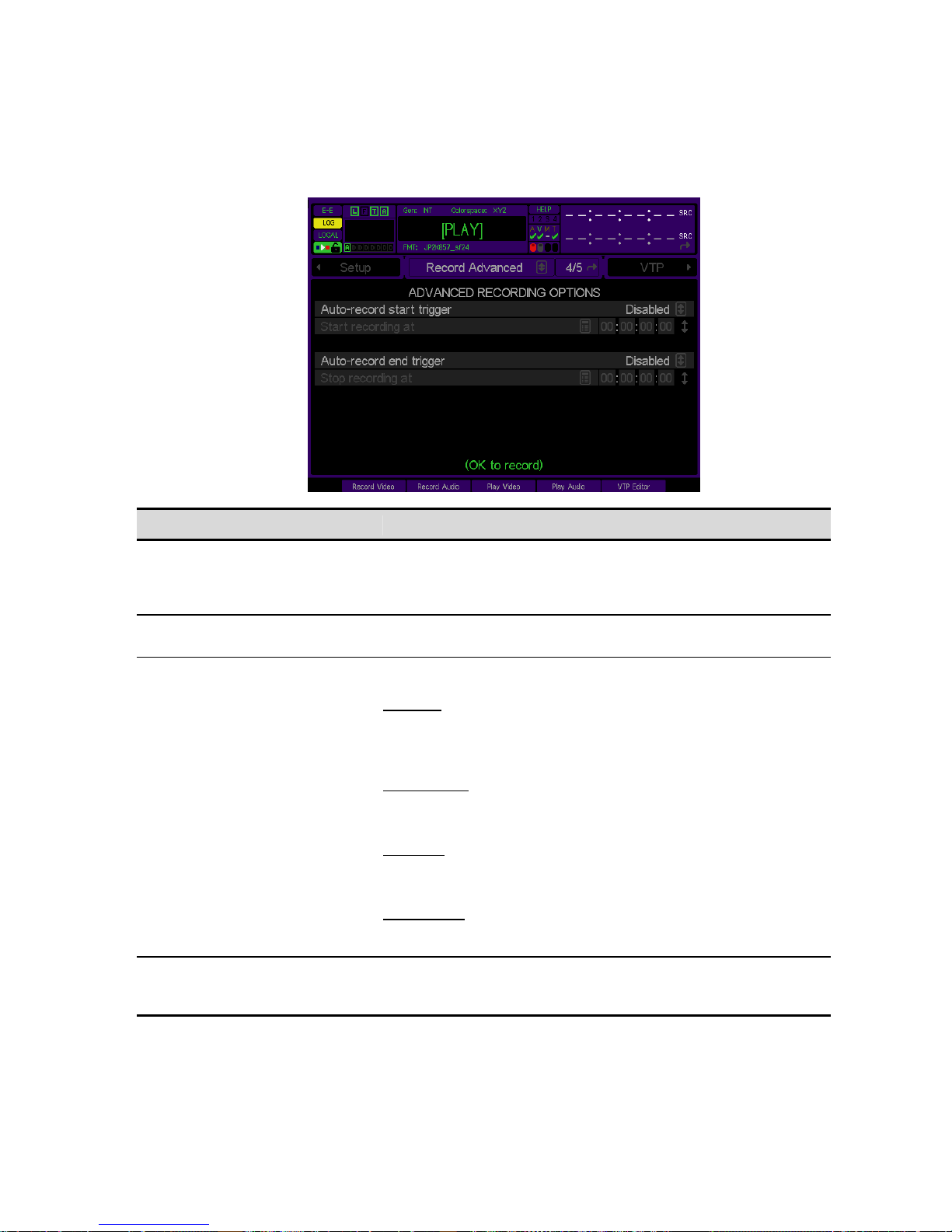
RECORD ADVANCED (4/5) menu page
This advanced panel allows you to setup a single automated record event based on several different “triggers”.
Record Advanced Options Description
This is the event that triggers the start of record. Choices include
Auto-record start trigger
Start recording at
Auto-record end trigger
Stop recording at
incoming LTC timecode or System Time (you can check the current
system time by clicking on the arrow button to the right of the lower
timecode display until it shows SYS).
Use this button to specify the system time or input timecode value
(LTC) at which the triggered recording should begin.
This is the event that triggers the end of recording. Choices include:
Disabled
To manually stop the triggered record session you must use the STOP
button on the front panel of the Acuity.
Elapsed Time
record session once the specified elapsed time, set the “Stop
recording at” button, has passed.
Timecode
recording once the LTC timecode value, set by the “Stop recording at”
button, has been received.
System Time
once the specified system time, set by the “Stop recording at” button,
has been reached.
Used to specify the time value associated with the selected “End
Trigger” method. Auto-record end trigger must be enabled to set the
end time of the triggered record event.
– Auto-record end trigger is turned off.
– Enables the Acuity to automatically end the triggered
– Enables the Acuity to automatically end the triggered
– This end trigger is used to automatically stop recording
QuVIS Acuity™ Page 99 QSR Version 3.3
 Loading...