

Page 1

ECHNICAL MANUAL
T
INTEGRITY 600 SERIES
AAB6214 ANALOG AUDIO
DISTRIBUTION AMPLIFIER
Publication: 81-9059-0631-0, Rev. A
July, 2008
Page 2

Integrity 600 – AAB6214 Analog Audio DA
Publication 81-9059-0631-0, Rev. A
July 2008
Thank You !! for purchasing your new A/V Processing Equipment from QuStream. We appreciate
your confidence in our products. QuStream produces quality, state-of-the-art equipment designed to
deliver our users the highest degree of performance, dependability and versatility available anywhere.
We want you to know that if you ever have a concern or problem with a QuStream product, we have a
team of engineers, technicians and customer service professionals available 24/7/365 to help resolve
the issue.
Our commitment is to continue earning the trust and confidence of our customers throughout the
industry by incorporating cutting-edge technology into the highest quality, most cost effective products
on the market. And we would like to invite you to tell us how we’re doing. If you have any comments
or suggestions concerning your QuStream equipment, please contact our Customer Service
Department.
Again thank you for choosing a QuStream product and we look forward to a long-term partnership
with you and your facility.
SERVICE AND ORDERING ASSISTANCE
QuStream
103 Quality Circle, Suite 210
Huntsville AL 35806 USA
www.qustream.com
MAIN OFFICE
Tel: 256.726.9200
Fax: 256.726.9271
© 2008 QuStream, All Rights Reserved.
“Fortel Inside” is a trademark of QuStream in the United States and/or other countries.
Microsoft, Windows, and Windows NT are either registered trademarks or trademarks of Microsoft Corporation in the United States and/or
other countries.
No part of this publication (including text, illustrations, tables, and charts) may be reproduced, stored in any retrieval system, or transmitted
in any form or by any means, including but not limited to electronic, mechanical, photocopying, recording or otherwise, without the prior
written permission of QuStream.
All information, illustrations, and specifications contained in this publication are based on the latest product information available at the time
of publication approval. The right is reserved to make changes at any time without notice.
Printed in the United States of America.
As of publication, this product had not completed FCC compliance testing.
July, 2008
SERVICE DEPARTMENT
Tel: 256.726.9222 (24/7)
Toll Free: 800.323.7372
Fax: 256.726.9268
Email: [email protected]
Proprietary Information of QuStream I
Page 3

Integrity 600 – AAB6214 Analog Audio DA
Publication 81-9059-0631-0, Rev. A
July 2008
TABLE OF CONTENTS
CHAPTER 1
1.1 DOCUMENTATION AND SAFETY OVERVIEW ............................................................................1-1
1.2 WARNINGS, CAUTIONS, AND NOTES .......................................................................................1-1
ABOUT THIS MANUAL....................................................................................... 1-1
1.2.1 Warning .................................................................................................................... 1-1
1.2.2 Caution ..................................................................................................................... 1-1
1.2.3 Note .......................................................................................................................... 1-1
CHAPTER 2 INTRODUCTION................................................................................................... 2-1
2.1 DESCRIPTION...........................................................................................................................2-1
CHAPTER 3 INSTALLATION.................................................................................................... 3-1
3.1 INTERNAL ROUTING CONSIDERATIONS ...................................................................................3-1
3.2 INSTALLATION PROCEDURE ....................................................................................................3-1
3.2.1 Install Rear Connector Panel .................................................................................... 3-2
3.2.2 Install Main Circuit Board........................................................................................ 3-3
3.3 REAR PANEL SIGNAL CONNECTIONS .......................................................................................3-4
3.4 INITIAL POWER-UP..................................................................................................................3-7
3.5 AAB6214 STATUS LEDS ........................................................................................................3-7
CHAPTER 4 OPERATION........................................................................................................... 4-1
4.1 OPERATION .............................................................................................................................4-1
4.2 MAIN MENU - SCREEN 1..........................................................................................................4-1
4.3 RESET VALUES MENU SCREEN................................................................................................4-2
4.4 MAIN MENU – SCREEN 2 .........................................................................................................4-3
4.5 STATUS AND ALARMS DISPLAY SCREEN .................................................................................4-4
4.6 AUDIO OUTPUT PHASE MENU SCREEN....................................................................................4-5
4.7 AUDIO OUTPUT MUTE MENU SCREEN.....................................................................................4-5
4.8 CARD INFORMATION MENU SCREEN .......................................................................................4-6
4.9 CHANGE NAME MENU SCREEN ...............................................................................................4-6
4.10 CONFIGURE ALARMS MENU SCREEN ......................................................................................4-7
Proprietary Information of QuStream II
Page 4

Integrity 600 – AAB6214 Analog Audio DA
Publication 81-9059-0631-0, Rev. A
July 2008
LIST OF FIGURES
F
IGURE 2-1 TYPICAL 600 SERIES MODULE .........................................................................................................2-1
FIGURE 3-1 INSTALLING REAR CONNECTOR PANEL ...........................................................................................3-3
FIGURE 3-2 INSTALLING MAIN CIRCUIT BOARD ................................................................................................. 3-4
FIGURE 3-3 AAB6214 MODULE - REAR PANEL CONNECTIONS..........................................................................3-5
FIGURE 3-4 6-PIN DETACHABLE CONNECTOR PIN-OUTS.................................................................................... 3-6
FIGURE 3-5 AAB6214 STATUS LEDS ................................................................................................................. 3-8
FIGURE 4-1 MAIN MENU SCREEN 1.....................................................................................................................4-1
FIGURE 4-2 MAIN MENU SCREEN SHOWING LINKED AUDIO CHANNELS ...........................................................4-2
FIGURE 4-3 RESET VALUES MENU SCREEN ........................................................................................................4-3
FIGURE 4-4 MAIN MENU SCREEN 2.....................................................................................................................4-3
FIGURE 4-5 STATUS AND ALARMS DISPLAY SCREEN ......................................................................................... 4-4
FIGURE 4-6 AUDIO OUTPUT PHASE MENU SCREEN ............................................................................................4-5
FIGURE 4-7 AUDIO OUTPUT MUTE MENU SCREEN .............................................................................................4-5
FIGURE 4-8 CARD INFORMATION DISPLAY SCREEN ........................................................................................... 4-6
FIGURE 4-9 CHANGE NAME MENU SCREEN ........................................................................................................ 4-7
FIGURE 4-10 KEYPAD ACCESS CODE PROMPT SCREEN ......................................................................................4-7
FIGURE 4-11 ALARM CONFIGURATION MENU SCREEN....................................................................................... 4-8
LIST OF TABLES
TABLE 3-1 6-PIN AUDIO CONNECTOR – PIN-OUT CHART ....................................................................3-6
Proprietary Information of QuStream III
Page 5
Chapter 1 About This Manual
1.1 DOCUMENTATION AND SAFETY OVERVIEW
This manual provides instructions for the installation, operation, and maintenance as well as a top-level
functional description of the Integrity 600 Series AAB6214 Analog Distribution Amplifier built by
QuStream.
It is the responsibility of all personnel involved in the installation, operation, and maintenance of the
equipment to know all the applicable safety regulations for the areas they will be working in. Under no
circumstances should any person perform any procedure or sequence in this manual if the
procedural sequence will directly conflict with local Safe Practices. Local Safe Practices shall remain
as the sole determining factor for performing any procedure or sequence outlined in this document.
1.2 WARNINGS, CAUTIONS, AND NOTES
Throughout this document, you should notice various Warnings, Cautions, and Notes. These addendum
statements supply necessary information pertaining to the text or topic they address. It is imperative that
audiences read and understand the statements to avoid possible loss of life, personal injury, and/or
destruction/damage to the equipment. These additional statements may also provide added information
that could enhance the operating characteristics of the equipment (i.e., Notes). Examples of the graphic
symbol used to identify each type of statement and the nature of the statement content are shown in the
following paragraphs:
Integrity 600 – AAB6214 Analog Audio DA
Publication 81-9059-0631-0, Rev. A
July 2008
1.2.1 WARNING
1.2.2 CAUTION
1.2.3 NOTE
Warning statements identify conditions or practices that can result in loss of
life or permanent personal injury if the instructions contained in the
statement are not complied with.
Caution statements identify conditions or practices that can result in
personal injury and/or damage to equipment if the instructions contained in
the statement are not complied with.
Notes are for information purposes only. However, they may contain
invaluable information important to the correct installation, operation,
and/or maintenance of the equipment.
Proprietary Information of QuStream 1-1
Page 6

2.1 DESCRIPTION
QuStream’s AAB6214 Analog Audio Distribution Amplifier is a member of the Integrity 600 Series of
video and audio processing products, featuring “Fortel Inside” Technology. It mounts in the FRM603
Chassis Frame and accepts an input of analog audio and provides multiple outputs of the audio signal.
Redundant power and control are optionally available to every processing module through the chassis
frame.
The AAB6214 dual input module is actually composed of two independent DAs – configured as dual
1X7 distribution amplifiers. Figure 2-1 shows, for reference only, a typical 600 Series module with a
single-width rear panel attached to the main circuit board.
Integrity 600 – AAB6214 Analog Audio DA
Publication 81-9059-0631-0, Rev. A
July 2008
Chapter 2 Introduction
Figure 2-1 Typical 600 Series Module
Primary Features
• Distribution amplifier with audio processing.
•
•
• Rear-panel 6-pin detachable connectors for input and output signals.
• Redundant power, reference and control are optionally available to every board for
• Field-configurable when installed in a FRM603 Frame equipped with the NET603 Frame
Proprietary Information of QuStream 2-1
2 analog audio inputs with seven audio outputs for each input (Dual 1X7).
Full audio processing with independent or group gain, channel swapping, phase inversion
and summing.
increased reliability.
Controller.
Page 7

Integrity 600 – AAB6214 Analog Audio DA
Publication 81-9059-0631-0, Rev. A
July 2008
Specifications
Input Level 28dBu MAX
Noise Factor -87dBu (0dB input gain), -91dBu (+6dB input gain)
Common Mode Rejection > 90dB @ 60Hz, 60dB @ 20kHz (tested +28dBu CM input)
Input Impedance 33kΩ
Maximum Output Levels +28dBu across hi-impedance load
+24dBm into 600Ω load (subject to a frame limit of 15 Watts
maximum to any one card)
Input Gain 0dB or +6dB
Output Gain 0dB, +3.5dB or +9.5dB
Output Impedance 66Ω
Frequency Response ±0.05 dB 20Hz to 20kHz
Stereo Phase Match < 1 degree at 20kHz
SNR 100dB
Inter-Modulation Distortion < .005%
Stereo Crosstalk - 96 dB 20Hz to 20kHz
Input Voltage + 24v from the mid-plane
Power < 6 watts
Environmental 0º C to 45º C
Proprietary Information of QuStream 2-2
Page 8

3.1 INTERNAL ROUTING CONSIDERATIONS
The AAB6214 analog DA module is not equipped for mid-plane routing functions. When determining
in which frame slot to install the module, you should consider whether or not internal signal routing
capabilities of the frame are to be used for signal input or output sharing by other modules installed in
the frame. For further information on planning an Integrity 600 Series system using internal routing
capability, refer to the Technical Manual for the FRM603 frame, QuStream Publication 81-9059-0622-0.
There are no restrictions on placing modules in the FRM603 frame – any module will function standalone in any slot. However, if you are intending to incorporate internal frame routing, adjacent module
signal sharing or Star Slot routing, you should have the system pre-planned prior to module installation.
QuStream recommends that you make a detailed drawing of your system and follow it when loading
modules into the frame. The following guidelines will help you in your system planning, but they are
not intended to be an all-inclusive, step-by-step guide.
• Make a listing of the modules you will use in your system, and determine the internal routing
capability of each module. Not all 600 Series modules share the same capabilities: for example
some of the 600 Series dual input distribution amplifiers are actually two independent
amplifiers; one of which can receive input signals from the module LEFT adjacent to it, or the
Star Slot A routing bus, and the other can receive input signals from the module RIGHT adjacent
to it, or the Star Slot B routing bus.
• Not all modules are equipped for internal signal routing. If you are going to use internal routing
in your layout, it would not be advisable to install modules without such capability in a Start
Slot or in a frame slot you may need for signal sharing.
• Consider placement of modules you intend to share signals first. Include in your sketch which
module will receive a signal from an external source, how you want signals distributed to other
modules and with which module the internal routing will terminate.
NTEGRITY 600 – AES600 FAMILY
I
Publication 81-9059-0632-0, Rev. A
June 2008
Chapter 3 Installation
3.2 INSTALLATION PROCEDURE
Every Integrity 600 Series processing module consists of a rear connector panel and the main circuit
card. These two items are shipped as a set, but must be installed individually into the FRM603 chassis
frame. The AAB6214 rear connector panel occupies one card slot in the FRM603, and may be installed
in any available slot in the chassis frame. Proper installation requires that the rear connector panel be
installed before the circuit board. Observe the following precautions before proceeding with
installation:
Proprietary Information of QuStream 3-1
Page 9

Damage may occur to the rear connector panel or the circuit board if the
installation instructions are not properly followed.
• Rear connector panel MUST be installed before the front-mounted circuit board.
• If a circuit board should occupy a chassis frame slot where a rear connector panel is to be
added or changed, the circuit card MUST be removed or slid out a minimum of two inches
from the front side of the chassis frame before installing the rear connector panel.
It is not necessary to remove power to the chassis frame prior to installing a processing module.
3.2.1 INSTALL REAR CONNECTOR PANEL
Install rear connector panel as follows:
CAUTION
NTEGRITY 600 – AES600 FAMILY
I
Publication 81-9059-0632-0, Rev. A
June 2008
1. If your processing module was shipped with the rear connector panel attached to the main circuit
board, separate the two units.
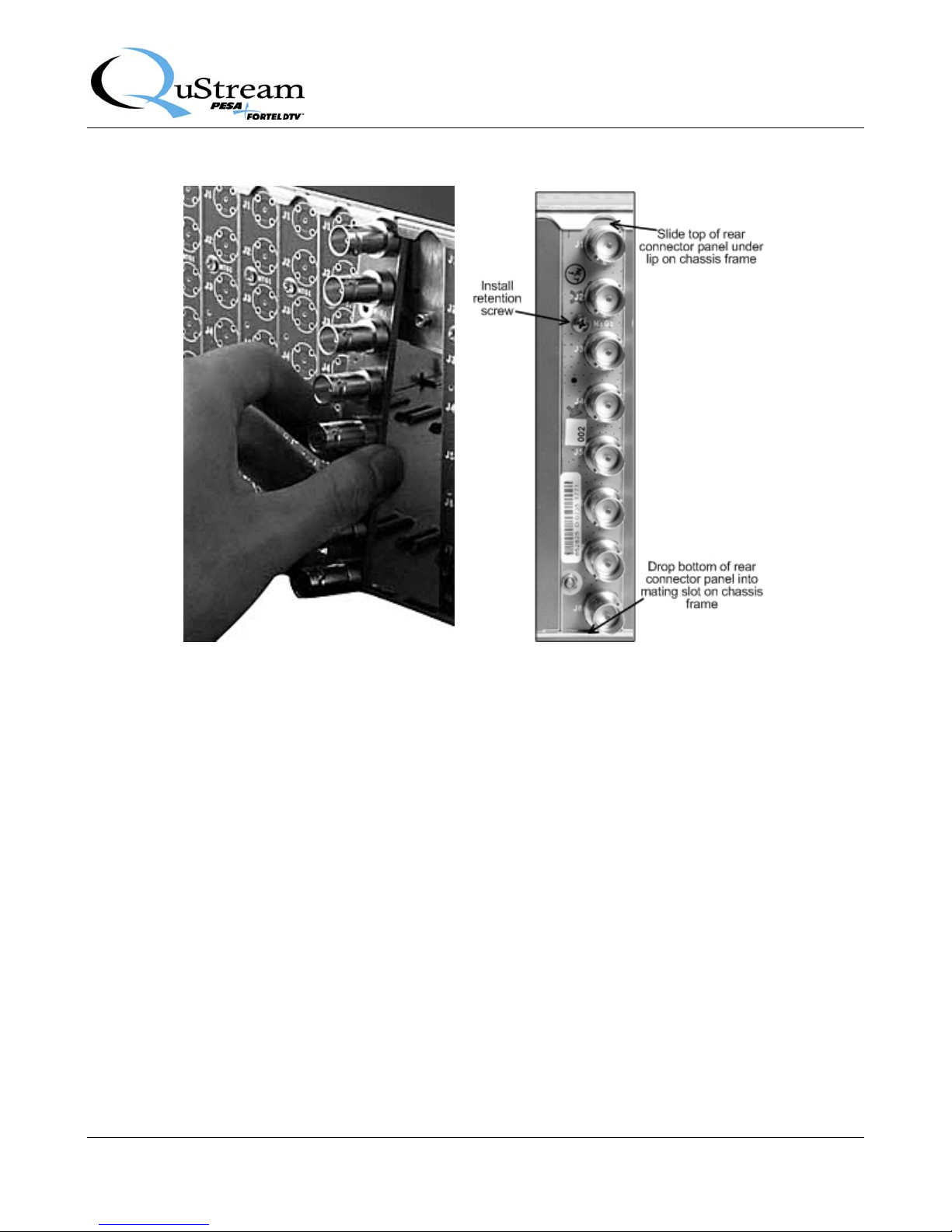
2. Figure 3-1 illustrates the connector panel installation process using a single-width panel fitted
with BNC connectors; however the procedure is identical for installing a rear panel equipped with
6-pin detachable connectors.
3. Orient the rear connector panel with the main board connector toward the lower edge of the
chassis.
4. Install the panel by pressing it upward under the top lip of the chassis frame, and move the panel
toward the chassis until it is flat against the chassis frame, refer to Figure 3-1.
5. Allow the bottom edge of the connector panel to drop down into its mating slot at the bottom of
the lower edge of the chassis.
6. Install retention screw through connector panel to chassis frame, but DO NOT fully tighten the
retention screw, leaving the rear panel freedom to move, until after the Main Circuit Board is
installed per Paragraph 3.2.2.
CAUTION
DO NOT fully tighten the retention screw until after the Main Circuit Board is
installed. Severe damage could occur to the main board connector if the rear
panel is tightly secured prior to installing the main board.
Proprietary Information of QuStream 3-2
Page 10
NTEGRITY 600 – AES600 FAMILY
I
Publication 81-9059-0632-0, Rev. A
June 2008
Figure 3-1 Installing Rear Connector Panel
3.2.2 INSTALL MAIN CIRCUIT BOARD
Install main circuit board as follows:
1. Open front access door on the FRM-603 chassis frame.
2. Locate the empty card slot that mates to the rear connector panel installed in the previous step.
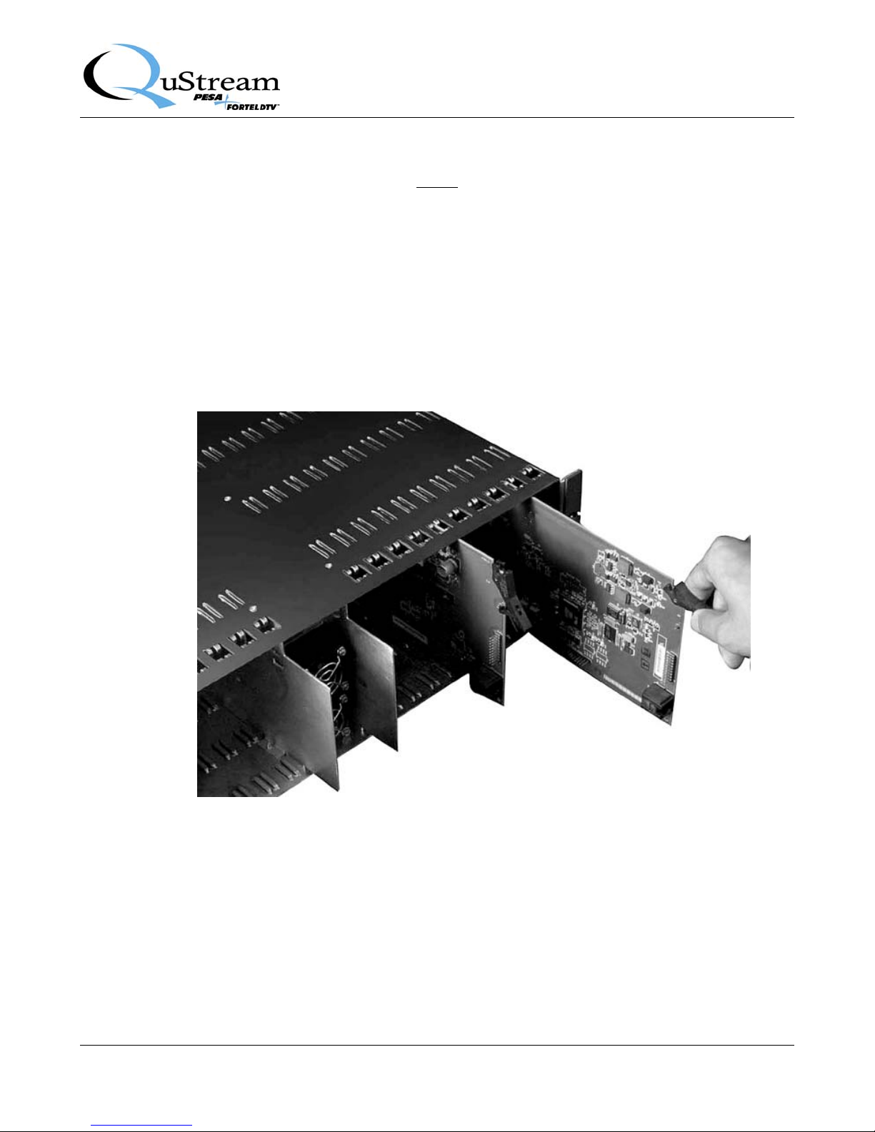
3. Align the top and bottom edges of the circuit board with the chassis card guides as shown in
Figure 3-2.
4. Hold the card ejector lever out (unlocked position) as shown when inserting the board.
5. Press the board into place to ensure solid connection with the mating connectors on the mid-plane
and rear connector panel.
Proprietary Information of QuStream 3-3
Page 11
NTEGRITY 600 – AES600 FAMILY
I
Publication 81-9059-0632-0, Rev. A
June 2008
NOTE
Do not force the card into position. If the card does not seat with gentle pressure, back it out,
realign with the card guides and reinsert the card.
6. When the card is properly seated, press the card ejector lever toward the board to lock the card in
position.
7. Once the main board is seated and locked, and all connectors have properly mated, secure the rear
connector panel to the chassis frame by tightening the retention screw.
8. Close the chassis frame front access door.
3.3 REAR PANEL SIGNAL CONNECTIONS
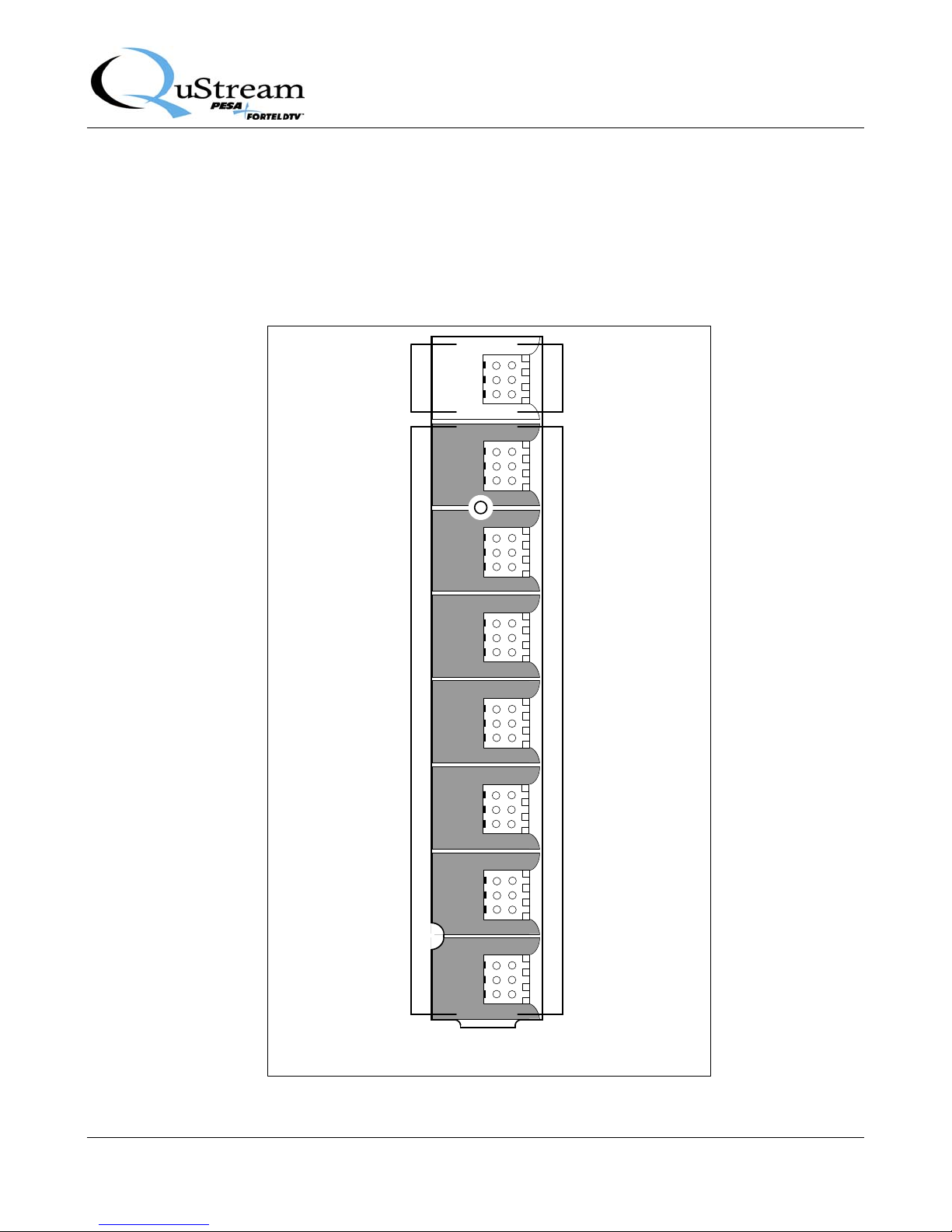
Input and output connections to the module are made through 6-pin detachable connectors on the singlewidth rear connector panel. Each connector provides 2 physical input or output connections for a total
of 2 Input and 14 Output connections on each rear panel. Rear connector panel layout is shown in
Figure 3-3. When making audio connections to the AAB6214 module, follow the pin-out data for rear
panel audio connections presented by Figure 3-4 and Table 3-1. Use good quality cable and ensure that
the mating plug is properly installed.
Proprietary Information of QuStream 3-4
Figure 3-2 Installing Main Circuit Board
Page 12
NTEGRITY 600 – AES600 FAMILY
I
Publication 81-9059-0632-0, Rev. A
June 2008
The mating plug used with the on-board connectors is a solderless type and uses a spring clamp to
securely hold input or output cable wires. Connections are made by inserting the wire end into the round
receptacle on the plug. The small square hole beside each wire receptacle contains a spring release that
loosens the clamp and allows the wire to be removed from its associated receptacle. To remove a wire,
simply insert the blade of a small flat tip screwdriver into the release hole adjacent to the receptacle
containing the wire you wish to remove, and gently pull the wire from the receptacle.
IN 2
DISTRIBUTION
AMPLIFIER 2
ANALOG AUDIO
INPUT
OUT 2.1 – OUT 2.7
DISTRIBUTION
AMPLIFIER 2
ANALOG AUDIO
OUTPUTS 1 - 7
In
1 & 2
Out
Out
1.1
&
2.1
Out
1.2
&
2.2
Out
Out
1.3
&
2.3
Out
Out
1.4
&
2.4
Out
Out
1.5
&
2.5
IN 1
DISTRIBUTION
AMPLIFIER 1
ANALOG AUDIO
INPUT
OUT 1.1 – OUT 1.7
DISTRUBITION
AMPLIFIER 1
ANALOG AUDIO
OUTPUTS 1 - 7
Figure 3-3 AAB6214 Module - Rear Panel Connections
Proprietary Information of QuStream 3-5
Out
1.6
&
2.6
Out
1.7
&
2.7
AAB6214
Page 13
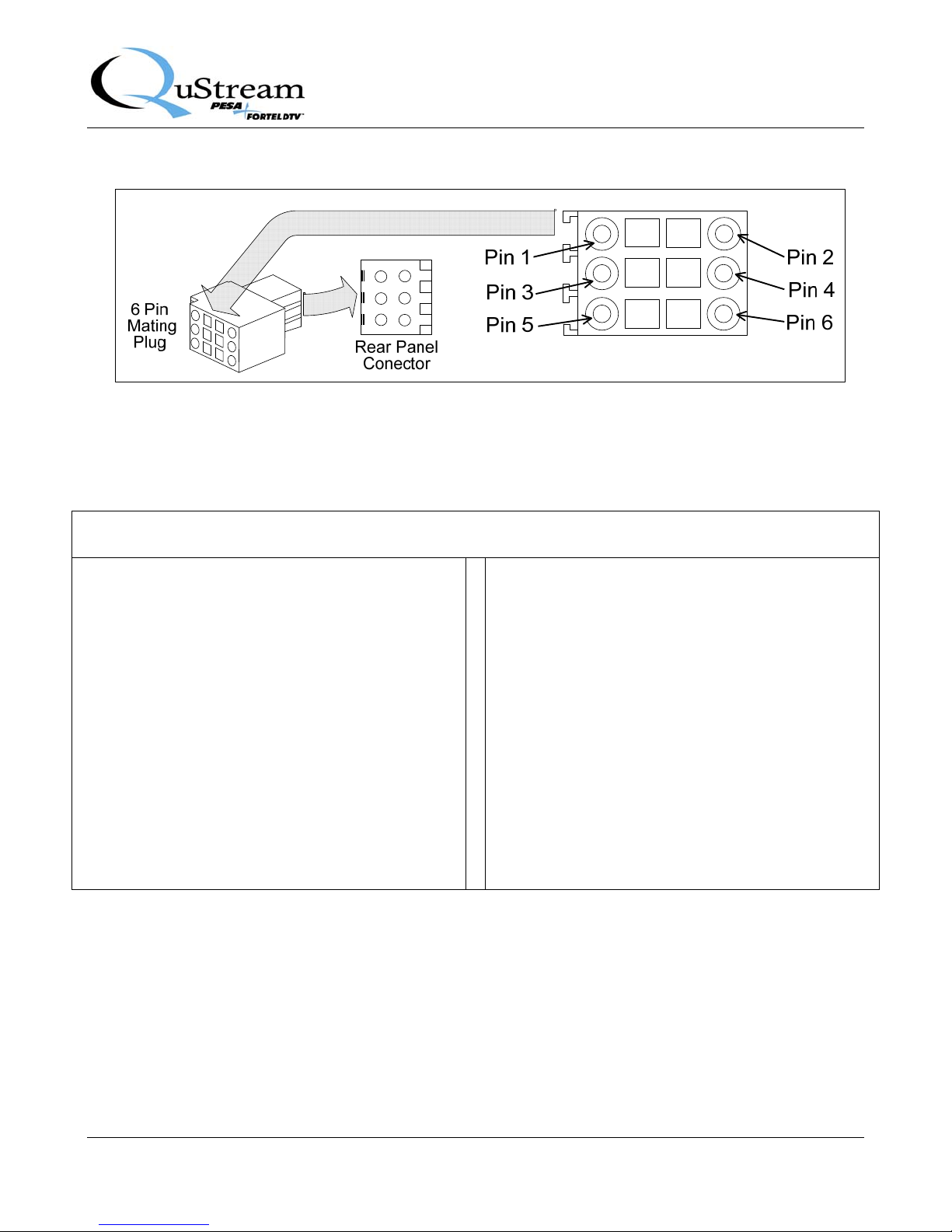
Figure 3-4 6-Pin Detachable Connector Pin-Outs
Table 3-1 6-Pin Audio Connector – Pin-Out Chart
Backplane
Connector Signal
Pos.
(+)
Pin
Neg.
(-)
Pin
Ground
(Shield)
Pin
NTEGRITY 600 – AES600 FAMILY
I
Publication 81-9059-0632-0, Rev. A
Backplane
Connector Signal
Pos.
(+)
Pin
June 2008
Neg.
(-)
Pin
Ground
(Shield)
Pin
In 1 & 2
In 1 & 2
Out 1.1 & 2.1 DA 1, Output 1 1 2 3 Out 1.5 & 2.5 DA 1, Output 5 1 2 3
Out 1.1 & 2.1 DA 2, Output 1 5 6 4 Out 1.5 & 2.5 DA 2, Output 5 5 6 4
Out 1.2 & 2.2 DA 1, Output 2 1 2 3 Out 1.6 & 2.6 DA 1, Output 6 1 2 3
Out 1.2 & 2.2 DA 2, Output 2 5 6 4 Out 1.6 & 2.6 DA 2, Output 6 5 6 4
Out 1.3 & 2.3 DA 1, Output 3 1 2 3 Out 1.7 & 2.7 DA 1, Output 7 1 2 3
Out 1.3 & 2.3 DA 2, Output 3 5 6 4 Out 1.7 & 2.7 DA 2, Output 7 5 6 4
DA Channel 1
Audio Input
DA Channel 2
Audio Input
1 2 3 Out 1.4 & 2.4 DA 1, Output 4 1 2 3
5 6 4 Out 1.4 & 2.4 DA 2, Output 4 5 6 4
Proprietary Information of QuStream 3-6
Page 14

3.4 INITIAL POWER-UP
It is not necessary to remove power when installing the AAB6214 module into an active chassis frame.
If this is an initial installation, before applying power for the first time, please take time to go back and
verify the following:
• Check for electrically sound connections, proper connector placement and possible wiring
errors.
• Ensure that the chassis frame has a connection to a source of in-house sync, if required for the
application.
• Check that all 600 Series modules, rear panels, power supply and controller modules are
securely installed.
There is no power switch on the frame, and it is powered-up simply by connecting the main power cord
to a source of primary power. Systems with redundant power supply modules have two main power
cords, each of which must be connected to a source of primary power.
When the AAB6214 module is initially powered up, look at the status LEDs located on the module
circuit board and verify proper operation as discussed in Paragraph 3.5.
NTEGRITY 600 – AES600 FAMILY
I
Publication 81-9059-0632-0, Rev. A
June 2008
3.5 AAB6214 STATUS LEDS
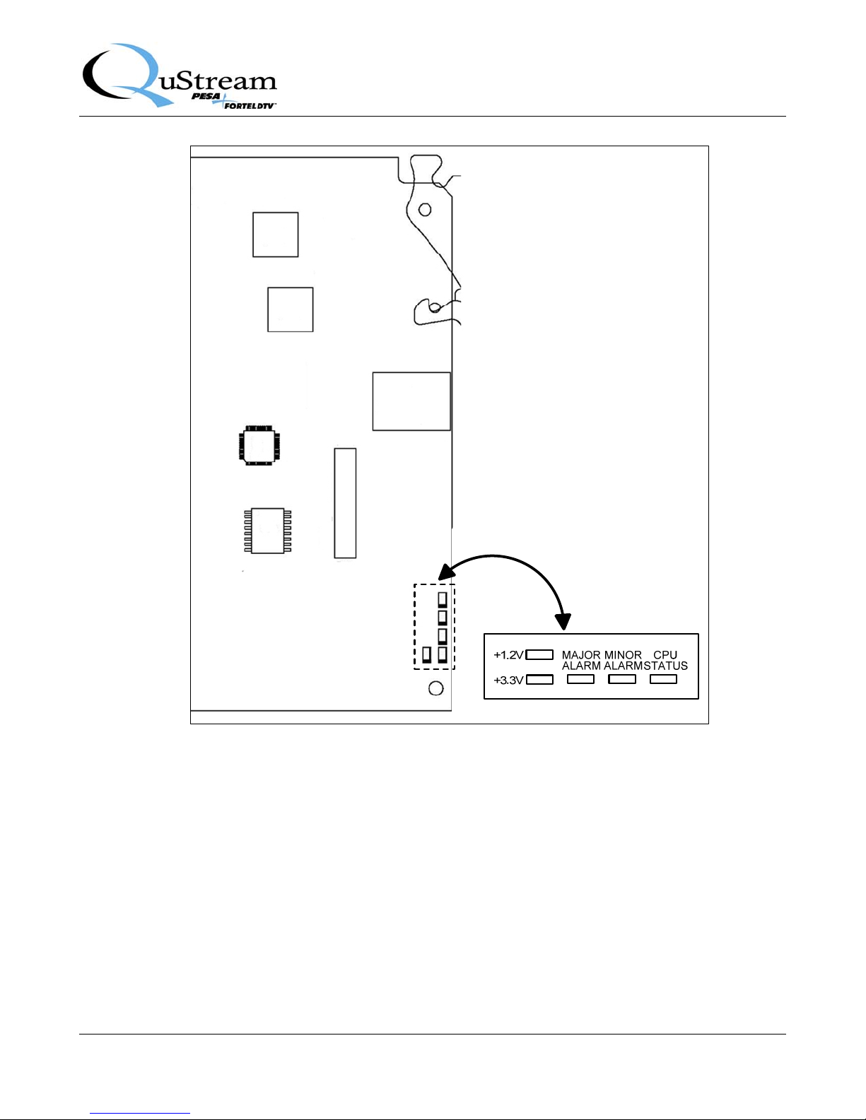
There are 5 status LEDs located on the circuit board of each AAB6214 module, as shown in Figure 3-5.
Proprietary Information of QuStream 3-7
Page 15
NTEGRITY 600 – AES600 FAMILY
I
Publication 81-9059-0632-0, Rev. A
June 2008
Verify that the LED indicators are showing the proper operating status of the module. The function of
each LED is discussed is discussed below.
• +1.2V – GREEN – When lit, indicates the 1.2V power supply is operational
• +3.3V – GREEN – When lit, indicates the 3.3V power supply is operational
• MAJOR ALARM – RED – When lit, indicates a major alarm condition detected
• MINOR ALARM – YELLOW – When lit, indicates a minor alarm condition detected
• CPU STATUS – GREEN – When flashing, indicates the CPU is active
Proprietary Information of QuStream 3-8
FIGURE 3-5 AAB6214 Status LEDs
Page 16
4.1 OPERATION
There are no operating controls located on the AAB600 modules. Certain operating parameters of the
DA module may be selected or modified through an external control device such as the Integrity 600
Series Remote Control Panel RCP-503, or the SOFT603 PC based software application, if the chassis
frame is equipped with at least one NET 603 Frame Controller module. While most installations do
contain the frame controller card, the AAB6214 module will function without a controller card present
in the frame; however, options from the configuration menus discussed in this chapter can not be chosen
or changed in the field. The module will be factory programmed prior to shipment. Refer to the RCP503 Technical Manual, QuStream Publication 81-9059-XXX-0 for control panel operation procedures.
The following paragraphs introduce the configuration options and adjustments available through each
configuration menu.
Integrity 600 – AAB6214 Analog Audio DA
Publication 81-9059-0631-0, Rev. A
July 2008
Chapter 4 Operation
4.2 MAIN MENU - SCREEN 1
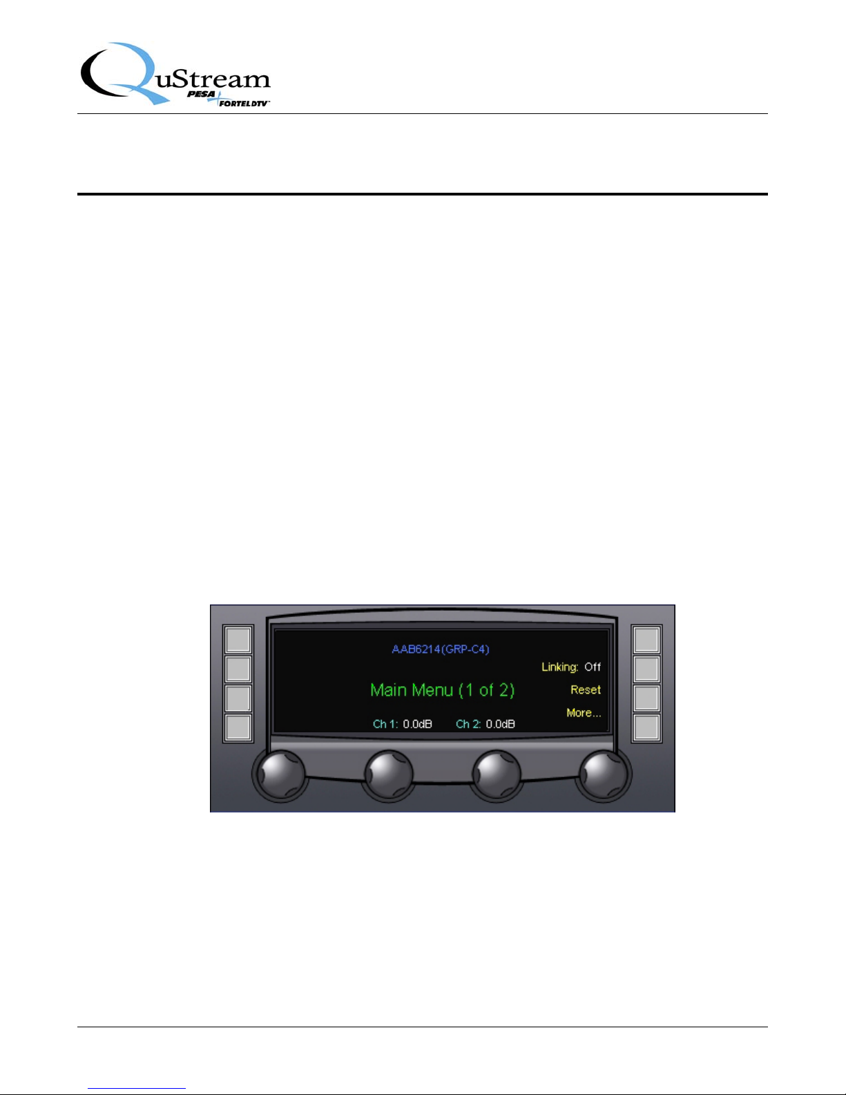
Figure 4-1 shows screen 1 of the main menu display for the AAB6214 DA module. Entries on the menu
screen and functions available through each are discussed below.
Figure 4-1 Main Menu Screen 1
LINKING
Gain of each analog input signal can be adjusted by selections on the main menu screen in one of two
ways - the audio channels may be adjusted independently (Linking Off) or the two signals may be
linked together (Linking On). When the signals are linked, gain for both channels is adjusted as a group
by a single control, and the balance between the two may be adjusted. Select the desired linking mode
Proprietary Information of QUSTREAM 4-1
Page 17
Integrity 600 – AAB6214 Analog Audio DA
Publication 81-9059-0631-0, Rev. A
July 2008
by pressing the touch-switch next to the Linking: On/Off menu item to toggle the linking function on
or off.
The Linking menu entry indicates the current active status of the signal linking function. When the
linking function is not active (off), the gain of each audio input signal may be independently adjusted as
required by rotating the control knob beneath the channel number display, as shown in Figure 4-1.
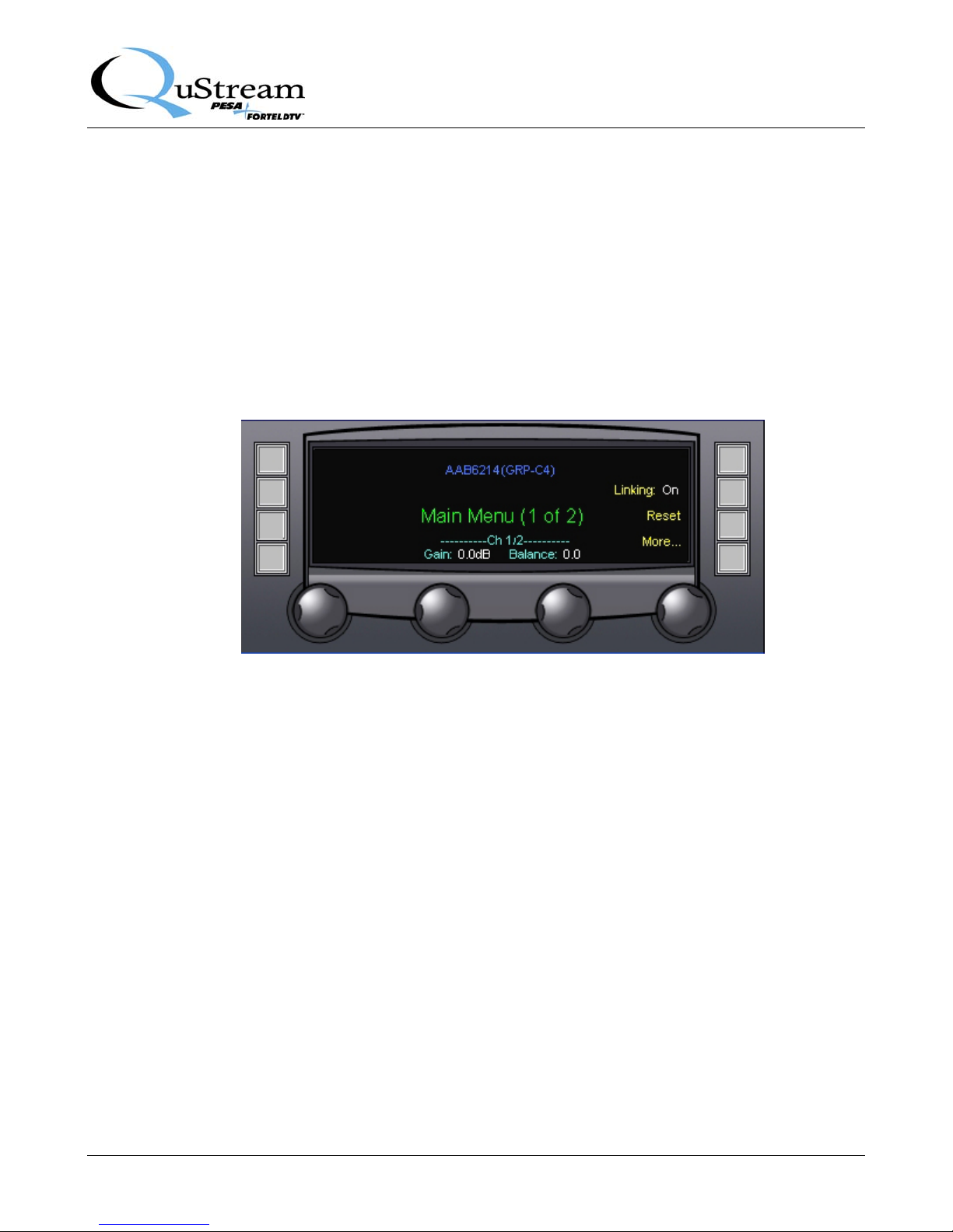
When Linking is set to On as shown in Figure 4-2, the audio channels are shown as being paired with a
single gain control. Gain for the linked pair may be adjusted as required by rotating the control knob
beneath the channel pair display. Balance between the two channels may be adjusted as required by
rotating the Balance control beneath the channel pair display.
Figure 4-2 Main Menu Screen Showing Linked Audio Channels
RESET
Pressing the touch-switch next to the Reset menu entry accesses the Reset Values Menu Screen,
discussed in Paragraph 4.3.
MORE
Pressing the touch-switch next to the More menu entry brings up screen 2 of the main menu, discussed
in Paragraph 4.4.
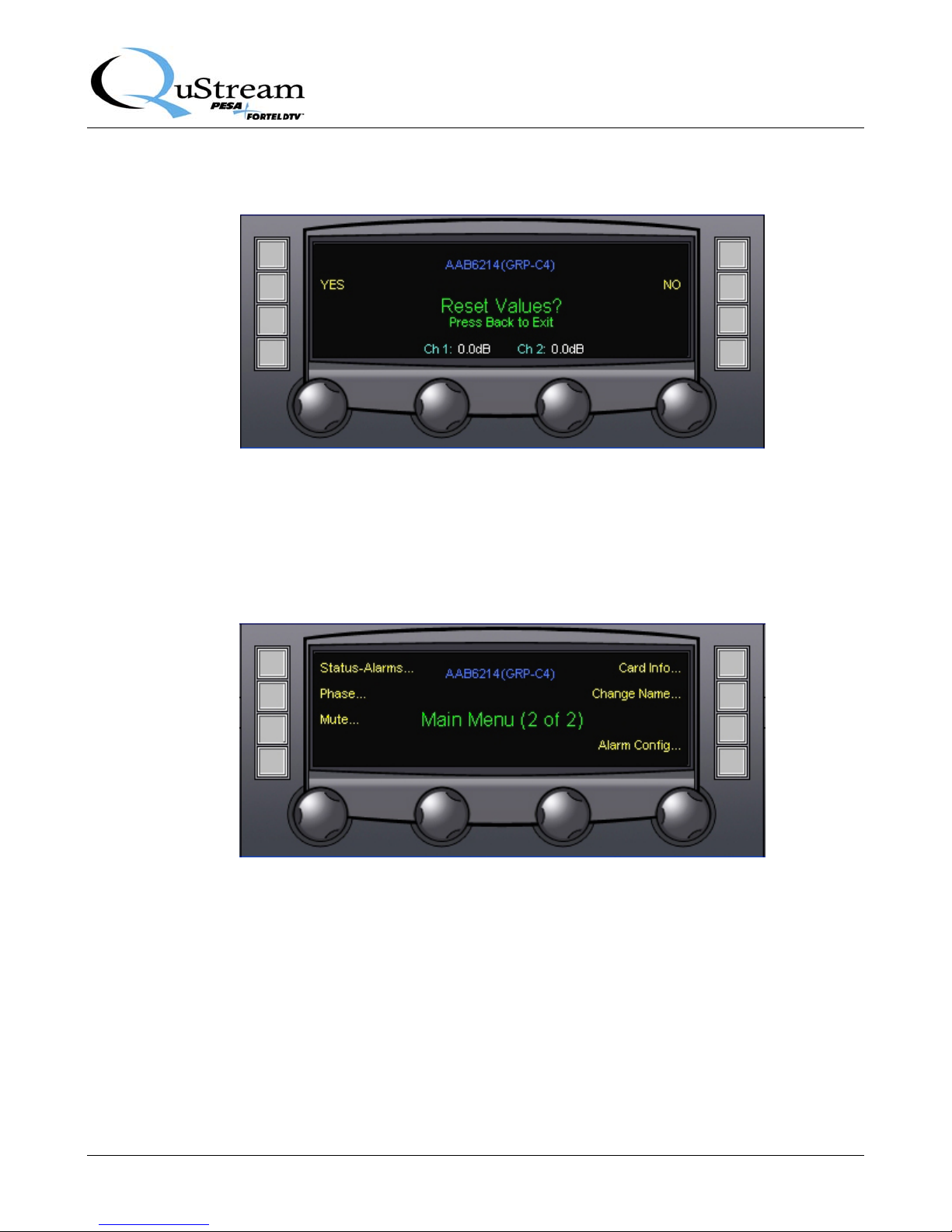
4.3 RESET VALUES MENU SCREEN
The Reset Values Menu Screen, Figure 4-3, displays the current settings for each audio signal along the
bottom edge of the display screen. Resetting the values returns each setting to the factory default. Press
the touch-switch next to the YES menu entry to accept and execute the reset function. Select the NO
menu entry to retain the current set values and return to the main menu display.
Proprietary Information of QUSTREAM 4-2
Page 18
Integrity 600 – AAB6214 Analog Audio DA
Publication 81-9059-0631-0, Rev. A
July 2008
Figure 4-3 Reset Values Menu Screen
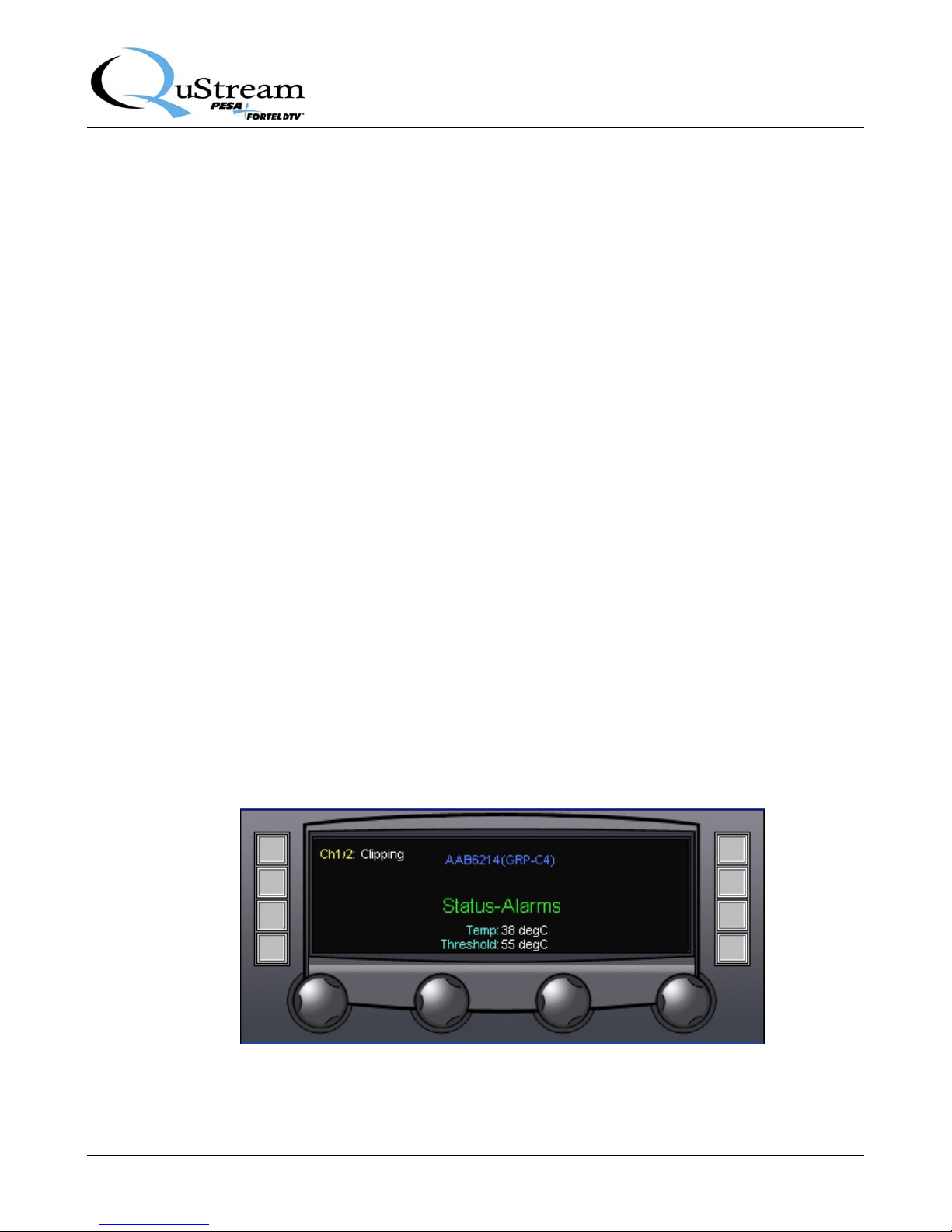
4.4 MAIN MENU – SCREEN 2
Screen 2 of the main menu is shown by Figure 4-4 and discussed in the following paragraphs.
STATUS-ALARMS
Pressing the touch-switch next to the Status-Alarms selection accesses the Status and Alarm Display
Screen, discussed in Paragraph 4.5.
Figure 4-4 Main Menu Screen 2
PHASE
Pressing the touch-switch next to the Phase selection accesses the Audio Phase Control Menu Screen,
discussed in Paragraph 4.6.
Proprietary Information of QUSTREAM 4-3
Page 19
Integrity 600 – AAB6214 Analog Audio DA
Publication 81-9059-0631-0, Rev. A
July 2008
MUTE
Pressing the touch-switch next to the Mute menu entry accesses the Audio Mute Control Menu Screen,
discussed in Paragraph 4.7.
CARD INFO
Pressing the touch-switch next to the Card Info menu entry accesses the Card Info Menu, discussed in
Paragraph 4.8.
CHANGE NAME
Pressing the touch-switch next to the Change Name menu entry accesses the Change Name Menu,
discussed in Paragraph 4.9.
ALARM CONFIGURATION
Pressing the touch-switch next to the Alarm Config menu item allows access to the Alarm
Configuration Menu Screen via the Access Code Screen, discussed in Paragraph 4.10.
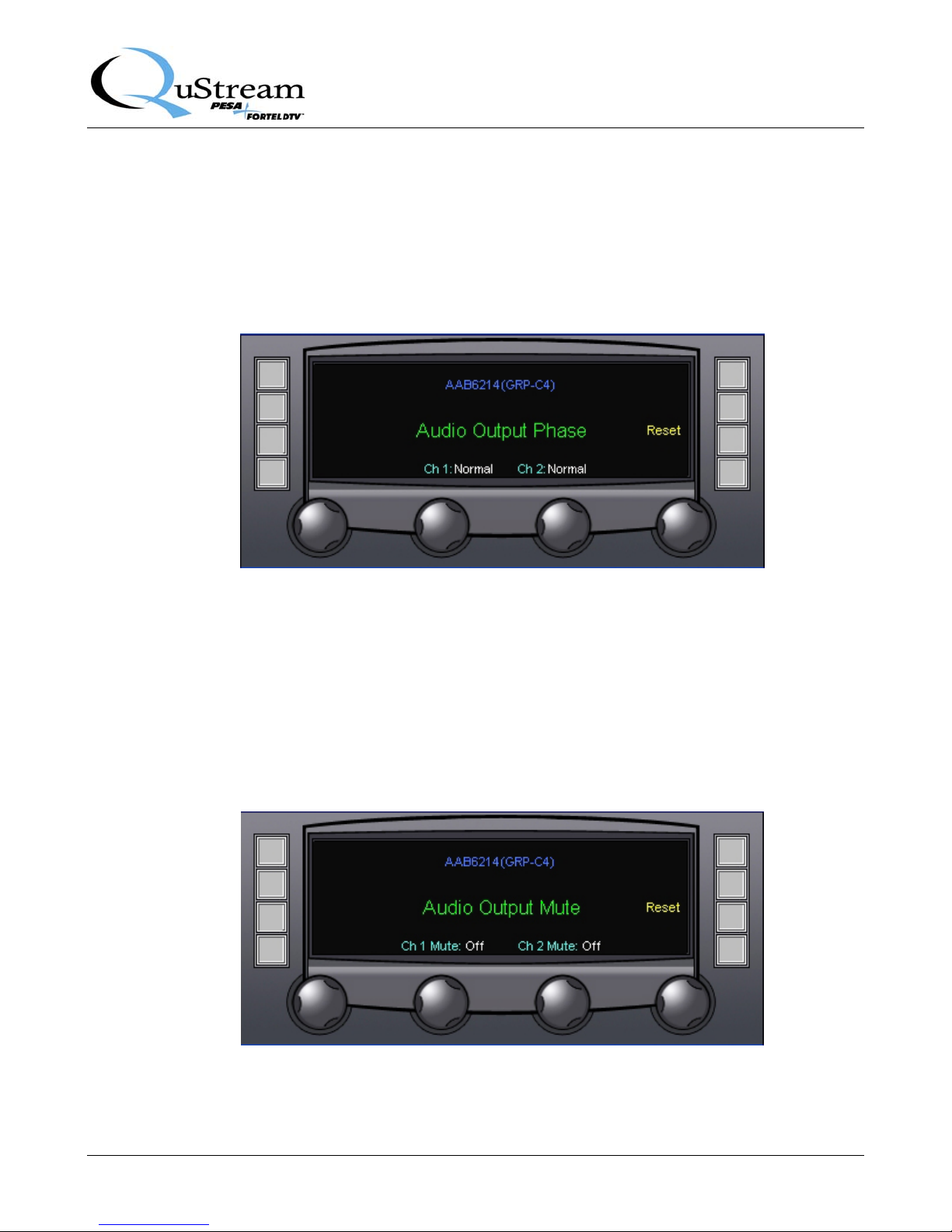
4.5 STATUS AND ALARMS DISPLAY SCREEN
The Status and Alarms Screen, Figure 4-5, displays the current status of the audio signal inputs and
module operating temperature. This is a display screen only – no configuration functions are accessible
from this screen.
Display entries along the left side indicate the status of audio channels. Current operating temperature of
the module is indicated by the Temp display. The Threshold entry displays the temperature selected
through the alarm configuration screen for activating an over-temperature status alarm.
Figure 4-5 Status and Alarms Display Screen
Proprietary Information of QUSTREAM 4-4
Page 20
4.6 AUDIO OUTPUT PHASE MENU SCREEN
Figure 4-6 illustrates the Audio Output Phase Menu Screen. Each audio channel is displayed at the
bottom of the screen, along with its current Normal/Inverted phase status. Rotating the control knob
beneath each audio channel applies or removes phase inversion for the indicated channel.
Pressing the touch-switch next to the Reset menu entry returns the module to factory default settings.
Integrity 600 – AAB6214 Analog Audio DA
Publication 81-9059-0631-0, Rev. A
July 2008
Figure 4-6 Audio Output Phase Menu Screen
4.7 AUDIO OUTPUT MUTE MENU SCREEN
Figure 4-7 illustrates the Audio Output Mute Menu Screen. Each audio channel is displayed at the
bottom of the screen, along with its current muting on or off status. Rotating the control knob beneath
each audio channel selects whether or not audio from the indicated channel is muted in the output
stream.
Pressing the touch-switch next to the Reset menu entry returns the module to factory default settings.
Figure 4-7 Audio Output Mute Menu Screen
Proprietary Information of QUSTREAM 4-5
Page 21
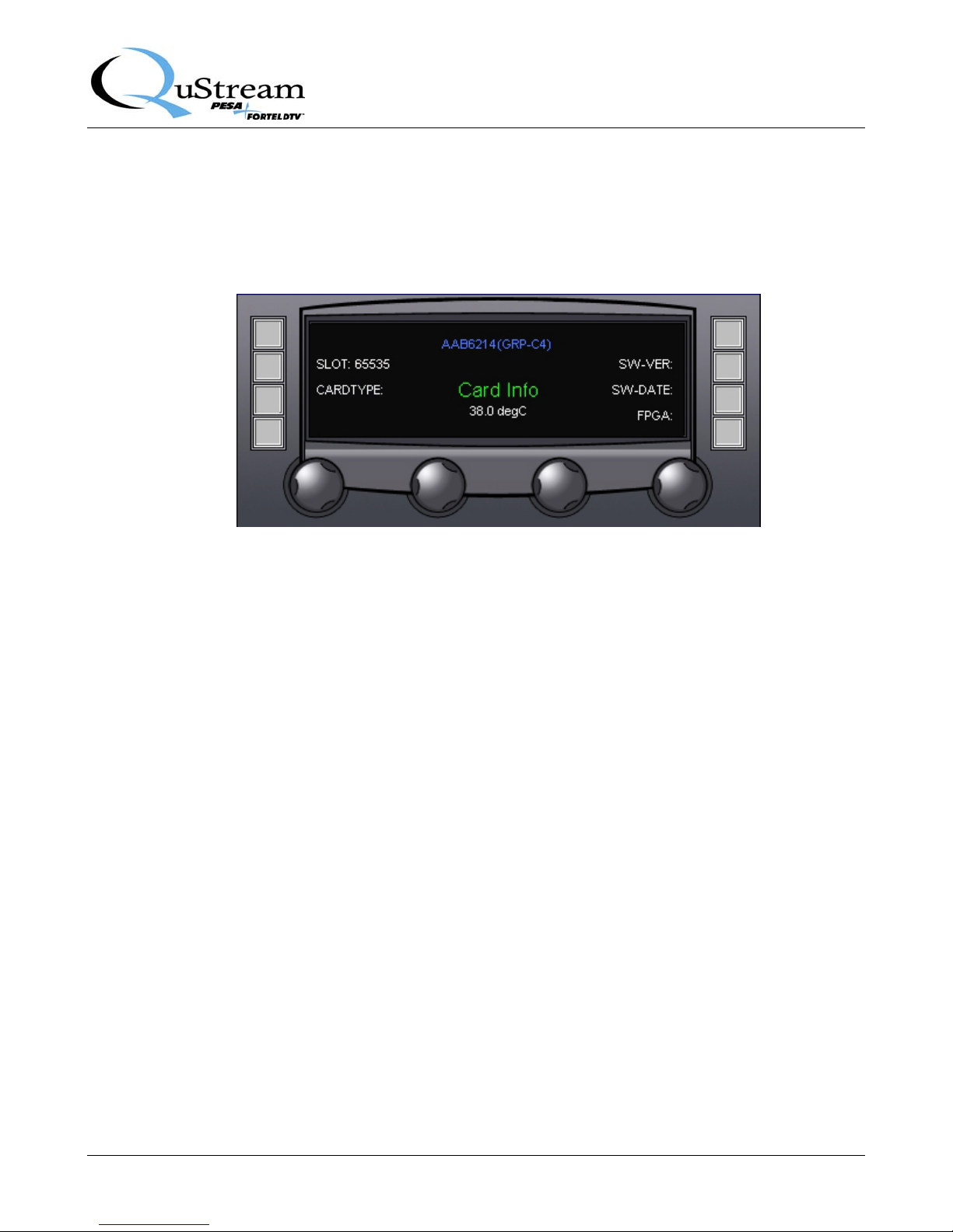
4.8 CARD INFORMATION MENU SCREEN
Enter the Card Information (Info) menu screen by pressing the touch-switch next to the Card Info entry
on main screen 2. Figure 4-8 shows the Card Info display screen.
Integrity 600 – AAB6214 Analog Audio DA
Publication 81-9059-0631-0, Rev. A
July 2008
Figure 4-8 Card Information Display Screen
The card information screen displays the following operational data for the AAB6214 module:
• Current operating temperature of the module is displayed in the center area of the screen
• SLOT – Identifies the card slot in the FRM603 frame where the AAB6214 module is located
• CARDTYPE – Identifies the model number of the AAB6214 module
• Software Version (SW-VER) – Displays the revision number of the currently loaded software
• Software Date (SW-DATE) – Displays the release date of the currently loaded software
• FPGA – Displays the revision number of the programming code loaded into the FPGA device
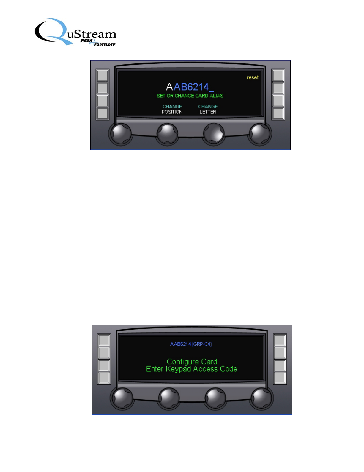
4.9 CHANGE NAME MENU SCREEN
Functions available through the Change Name menu screen allow you to enter a descriptive
identification name, or alias – up to 8 characters - for the AAB6214 module. Typical application of this
feature would be to name the AAB module in such a way to associate it with its input signals or
function. Figure 4-9 shows the Change Name menu display for the AAB6214 module.
Proprietary Information of QUSTREAM 4-6
Page 22
Integrity 600 – AAB6214 Analog Audio DA
Publication 81-9059-0631-0, Rev. A
Figure 4-9 Change Name Menu Screen
CHANGE POSITION
Rotating the CHANGE POSITION control moves the cursor to the desired character position to enter or
change.
July 2008
CHANGE LETTER
Rotating the CHANGE LETTER control scrolls through all alphanumeric display characters - letters,
numbers and punctuation marks are available. Once the desired character is displayed in the cursor
position, simply move the cursor to the next position.
RESET
Pressing the touch-switch next to the reset menu entry sets the name display to the default card alias.
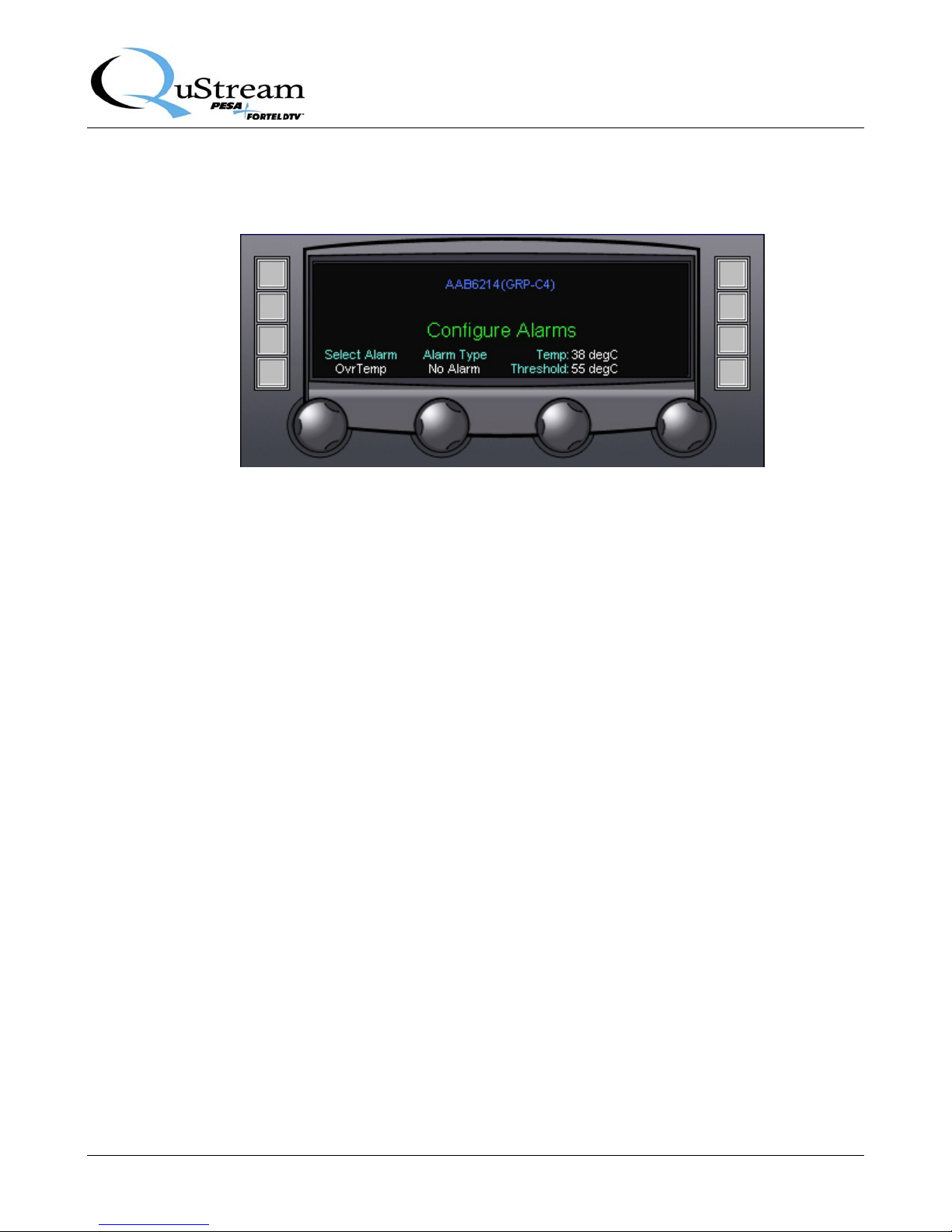
4.10 CONFIGURE ALARMS MENU SCREEN
Enter the Configure Alarms menu screen by pressing the touch-switch next to the Alarm Config entry
on main screen 2. Before you can gain access to the alarm configuration screen, you will be prompted
for the proper access code as shown in Figure 4-10.
Figure 4-10 Keypad Access Code Prompt Screen
Proprietary Information of QUSTREAM 4-7
Page 23
Integrity 600 – AAB6214 Analog Audio DA
Publication 81-9059-0631-0, Rev. A
July 2008
Enter the access code on the control panel keypad to access the Configure Alarms screen, as shown by
Figure 4-11. Entries on the menu screen and functions available through each are discussed below.
Figure 4-11 Alarm Configuration Menu Screen
SELECT ALARM
Select Alarm allows selection of the board function and parameters to associate with an alarm condition.
Alarm function may be selected by rotating the control knob beneath the Select Alarm display. The
following alarm options are available:
• Over Temperature (OvrTemp) – Triggers an alarm alert condition if the operating temperature
of the AAB module reaches or exceeds the selected threshold temperature
• Clipping 1 (OvrFlow1) – Triggers an alarm if the first input exceeds the set input level and
causes clipping of the signal
• Clipping 2 (OvrFlow2) – Triggers an alarm if the second input exceeds the set input level and
causes clipping of the signal
• I/O Board (IOB) – Triggers an alarm if the board is operated from a slot with the wrong I/O
board installed
• Power Overload (POL) – Triggers an alarm if the total output load exceeds the capacity of the
output power regulators, causing the outputs to trip off-line
ALARM TYPE
The setting of the Alarm Type selector determines which, if any, alarm is associated with the board
function selection. The following configuration options are available:
• No Alarm – The displayed alarm selection is not associated with any of the available alarms
• Minor Alarm - The displayed alarm selection will trigger a minor alarm indication when the
alarm trip condition exists
• Major Alarm - The displayed alarm selection will trigger a major alarm indication when the
alarm trip condition exists
Proprietary Information of QUSTREAM 4-8
Page 24

Integrity 600 – AAB6214 Analog Audio DA
Publication 81-9059-0631-0, Rev. A
July 2008
TEMPERATURE
The temperature (temp:) display indicates the current operating temperature of the AAB6214 module.
This is a display only function.
THRESHOLD
Rotating the control knob beneath the Threshold menu entry determines the temperature (in degrees
Celsius) at which the Over Temp alarm triggers.
NOTE
Temperature and Threshold values are only displayed when the Select Alarm
control is set to the Over Temperature (OvrTemp) selection.
Proprietary Information of QUSTREAM 4-9
Page 25

 Loading...