

Quorum Q150T S, Q150T E, Q150T ES Instruction Manual
Q150T S/E/ES
Sample Preparation System
Instruction Manual
10473
Issue 5
For technical and applications advice plus our on-line shop for
spares and consumable parts visit www.quorumtech.com
Quorum Technologies Ltd.
Judges House
Lewes Road
Laughton
East Sussex
BN8 6BN
Tel: +44(0) 1323 810981
Email: mailto:sales@quorumtech.com
Web : http://www.quorumtech.com
For technical and applications advice plus our on-line shop for spares and consumable
parts visit www.quorumtech.com
Issue Date Details Revised By
1 03/06/10 Initial Issue SRM
2 20/08/10 Glow discharge updates SRM
3 31/01/12 Ramped profile, Aperture cleaning update, Aluminium coating SRM
4 04/02/13 Gas supply, rod shaping instructions, outgassing SRM
5 16/07/14 Addition of controlled pulse carbon and other corrections SRM
Disclaimer
The components and packages described in this document are mutually compatible and
guaranteed to meet or exceed the published performance specifications. No performance
guarantees, however, can be given in circumstances where these component packages are used
in conjunction with equipment supplied by companies other than Quorum Technologies Ltd.
www.quorumtech.com
Quorum Technologies Limited Company No. 04273003
Registered Office: Unit 19, Charlwoods Road, East Grinstead, West Sussex, RH19 2HL, UK

Q150T Sample Preparation System
Contents
Section Contents
1 Introduction.......................................................................................................... 8
1.1 General Description .........................................................................................8
1.2 Sputter Coating................................................................................................ 9
1.3 Carbon Coating................................................................................................ 9
1.4 Metal Evaporation ............................................................................................9
1.5 Aperture Cleaning ............................................................................................9
2 Installation.......................................................................................................... 10
2.1 Pre-installation............................................................................................... 10
2.1.1 Required Services .......................................................................................................10
2.2 Unpacking...................................................................................................... 11
2.3 Connections................................................................................................... 12
2.3.1 Gas Connections ........................................................................................................ 13
2.3.2 Electrical Connections.................................................................................................14
2.3.3 Aux Network Connection.............................................................................................14
2.3.4 Vacuum Connections ..................................................................................................15
2.3.5 Fitting the Standard Stage...........................................................................................16
2.3.6 Optional Connections ..................................................................................................16
3 Operation............................................................................................................ 17
3.1 Switching On for the First Time ...................................................................... 17
3.1.1 The Standby screen ....................................................................................................17
3.2 Running a Profile ...........................................................................................18
3.3 System Settings............................................................................................. 20
4 Working with Profiles......................................................................................... 21
4.1 Editing the Active Profile ................................................................................21
4.2 Profile Editor ..................................................................................................21
4.2.1 Creating a New Profile ................................................................................................23
4.2.2 Editing Profile Parameters...........................................................................................24
4.3 Materials........................................................................................................ 25
4.3.1 Creating a New Material ..............................................................................................26
4.3.2 Editing Material Parameters ........................................................................................ 26
4.3.3 Deleting a Material....................................................................................................... 27
5 Application Guidelines ...................................................................................... 28
5.1 QT Timed Sputter .......................................................................................... 28
5.1.1 Tungsten SEM work.................................................................................................... 28
5.1.2 High resolution SEM coatings for field emission SEM ................................................28
5.1.3 Aluminium thin film...................................................................................................... 29
5.2 QT FTM Terminated Sputter........................................................................... 30
5.2.1 High resolution SEM coatings for field emission SEM ................................................30
5.2.2 General thin film coatings ............................................................................................ 30
5.3 Metal Evaporation .......................................................................................... 31
5.3.1 How to achieve a 20nm gold coating ...........................................................................31
5.4 Pulsed Cord Evaporation................................................................................ 32
5.4.1 How to create a 20nm carbon coating .........................................................................32
5.5 Controlled Pulse Cord Evaporation................................................................. 32
5.5.1 Using Controlled Pulse to create a 15nm coat or 2-3nm for EBSD ............................. 32
5.6 Pulsed Rod Evaporation................................................................................. 34
5.6.1 How to create a conductive layer for SEM................................................................... 34
5.7 Ramped Profile .............................................................................................. 35
5.7.1 Carbon insert setup..................................................................................................... 35
5.7.2 The ramped current profile .......................................................................................... 36
5.7.3 Adjusting coating thickness.........................................................................................37
5.7.4 How to create a carbon support layer For TEM........................................................... 37
How to create a conductive carbon layer for SEM .................................................................... 38
5.8 Using Outgas Source options ......................................................................... 39
5.8.1 Setting Outgas Source options ...................................................................................39
5.8.2 Running Multiple Outgassing ......................................................................................39
5.9 Glow Discharge..............................................................................................40
5.9.1 Hydrophilisation ........................................................................................................... 40
5.9.2 Surface Cleaning......................................................................................................... 40
Q150T - Instruction Manual 3 10473 - Issue 5

Q150T Sample Preparation System
5.10 Aperture Cleaning .......................................................................................... 41
6 Instrument Management .................................................................................... 42
6.1 The Q150T Menus ......................................................................................... 42
6.2 Instrument Settings ........................................................................................ 43
6.2.1 Network .......................................................................................................................44
6.2.2 Generic Sputter ...........................................................................................................45
6.2.3 Vacuum....................................................................................................................... 46
6.2.4 Maintenance................................................................................................................47
6.2.5 Hardware..................................................................................................................... 48
6.3 User Management.......................................................................................... 49
6.3.1 Changing User Group .................................................................................................49
6.3.2 Managing User Groups ...............................................................................................50
6.4 Film Thickness Monitor ..................................................................................51
6.5 Setting the Date and Time.............................................................................. 51
6.6 Setting up a Network connection .................................................................... 52
6.6.1 Configuring a Firewall Exception for Windows Explorer.............................................. 52
6.6.2 Connecting the Q150 ..................................................................................................52
6.6.3 Network Troubleshooting ............................................................................................ 53
6.7 Process Logging ............................................................................................53
7 Accessories ........................................................................................................ 54
7.1 Sputter Insert .................................................................................................54
7.2 Carbon Rod Insert.......................................................................................... 56
7.2.1 Shaping Carbon Rods for Pulsed Evaporation............................................................57
7.2.2 Shaping Carbon Rods for Ramped Evaporation .........................................................58
7.3 Fitting the Carbon Fibre Insert ........................................................................ 58
7.4 Metal Evaporation Insert ................................................................................ 59
7.4.1 Installing a Wire Basket ..............................................................................................59
7.4.2 Installing a Molybdenum Boat for Aperture Cleaning...................................................59
7.4.3 Adapting the Insert for Upwards Evaporation..............................................................60
7.5 Glow Discharge Insert .................................................................................... 62
7.6 Rotacota Stage .............................................................................................. 64
7.7 Slide Stage ....................................................................................................65
7.8 102mm Stage and Gearbox ........................................................................... 66
7.9 Tilt Stage ....................................................................................................... 67
7.10 Film Thickness Monitor (FTM)........................................................................ 68
7.10.1 Replacing the FTM crystal ..........................................................................................68
7.11 Extended Height Cylinder ............................................................................... 69
7.12 Full Range Vacuum Gauge Assembly ............................................................69
7.13 Rotating Vacuum Spigot ................................................................................70
7.14 Emergency Stop Module ................................................................................ 71
7.15 Spares ........................................................................................................... 72
7.16 Other Accessories.......................................................................................... 73
8 Service and Maintenance................................................................................... 74
8.1 Maintenance ..................................................................................................74
8.2 Troubleshooting ............................................................................................. 75
8.3 Error Messages.............................................................................................. 75
9 Appendices......................................................................................................... 78
9.1 Profile Parameters .........................................................................................78
9.2 System Overrideable Parameters ................................................................... 83
9.3 Technical Specification................................................................................... 84
9.4 Sputtering Deposition Rate............................................................................. 85
9.5 Return of Goods............................................................................................. 88
9.5.1 General Introduction .................................................................................................... 88
9.5.2 Health and Safety Declaration ..................................................................................... 88
9.5.3 Despatch ..................................................................................................................... 88
9.5.4 Return Address: .......................................................................................................... 88
9.5.5 Declaration of Contamination Form ............................................................................. 89
10 Index ................................................................................................................... 90
10473 - Issue 5 4 Q150T - Instruction Manual

Q150T Sample Preparation System
List of Figures
Figure 1-1. Front view of the Q150T................................................................................................8
Figure 2-1. Q150T Rear Panel ......................................................................................................12
Figure 2-2. Gas connectors with filter (part no. 12842) fitted to purge gas inlet ............................13
Figure 2-3. Power outlet lead wiring............................................................................................... 14
Figure 2-4. Fitting the standard stage............................................................................................ 16
Figure 3-1. Standby screen ...........................................................................................................17
Figure 3-2. Selecting a profile........................................................................................................ 18
Figure 3-3. A run in progress: with FTM installed (left) and without FTM (right). ..........................19
Figure 3-4. Venting the chamber: with FTM installed (left) and without FTM (right). ..................... 19
Figure 3-5. Listing system properties for a profile.......................................................................... 20
Figure 3-6. Changing the Stage Rotate system property ............................................................... 20
Figure 4-1. Profile Editor................................................................................................................21
Figure 4-2. Creating a new profile.................................................................................................. 23
Figure 4-3. Entering a new profile name ........................................................................................ 23
Figure 4-4. Editing Profile Parameters........................................................................................... 24
Figure 4-5. Materials Editor ...........................................................................................................25
Figure 4-6. Material Parameters ....................................................................................................27
Figure 5-1. QT Metal evaporation process ....................................................................................31
Figure 5-2. Typical 12nm Controlled pulse evaporation ................................................................. 33
Figure 5-3. Wedge tool (Part No. 12097) ......................................................................................35
Figure 5-4. (l) A finished wedge-shaped rod; and (r) in position with plain rod ..............................35
Figure 5-5. Ramped Profile with default parameters...................................................................... 36
Figure 5-6. Prompts to repeat the outgas procedure (left) and proceed with coating (right) ..........39
Figure 5-7. Aperture cleaning in progress .....................................................................................41
Figure 6-1. System Editor..............................................................................................................43
Figure 6-2. Network properties ......................................................................................................44
Figure 6-3. Active ftp address .......................................................................................................44
Figure 6-4. Generic sputter parameters......................................................................................... 45
Figure 6-5. Vacuum parameters .................................................................................................... 46
Figure 6-6. Maintenance settings ..................................................................................................47
Figure 6-7. Hardware settings (single target) ................................................................................48
Figure 6-8. Changing the user level...............................................................................................49
Figure 6-9. Managing user groups ................................................................................................50
Figure 6-10. FTM Status .................................................................................................................51
Figure 6-11. Setting the date and time............................................................................................. 51
Figure 6-12. Connecting the Q150 to a network ..............................................................................52
Figure 6-13. Process log and browse buttons .................................................................................53
Figure 6-14. Process log detail ........................................................................................................ 53
Figure 7-1. Top view of the sputter insert ......................................................................................54
Figure 7-2. Sputter insert and target assembly.............................................................................. 55
Figure 7-3. Carbon Rod Insert.......................................................................................................56
Figure 7-4. Recommended Carbon Rod shapes ...........................................................................57
Figure 7-5. Carbon Rod Shaper (S8650/S8651))..........................................................................57
Figure 7-6. Carbon string insert..................................................................................................... 58
Figure 7-7. Fitting the metal evaporation insert for downwards evaporation...................................59
Figure 7-8. Metal evaporation insert adapted for upwards evaporation ..........................................61
Figure 7-9. Glow discharge insert..................................................................................................62
Figure 7-10. Removing the shutter ..................................................................................................63
Figure 7-11. Rotacota stage ............................................................................................................ 64
Figure 7-12. Slide stage ..................................................................................................................65
Figure 7-13. Large (102mm) Sample Stage and gearbox ................................................................ 66
Figure 7-14. Adjustable tilting stage ................................................................................................67
Figure 7-15. FTM (left); replacing the FTM crystal (centre); FTM lead (right) .................................68
Figure 7-16. The extended height cylinder in position...................................................................... 69
Figure 7-17. Rotating vacuum spigot...............................................................................................70
Figure 7-18. The emergency stop module ....................................................................................... 71
Figure 7-19. Connecting the emergency stop module .....................................................................71
Figure 9-1. Sputtering Deposition Rate using Gold .......................................................................85
Figure 9-2. Sputtering Deposition Rate using Chromium ..............................................................86
Figure 9-3. Sputtering Deposition Rate using Silver ......................................................................87
Q150T - Instruction Manual 5 10473 - Issue 5

Q150T Sample Preparation System
List of Tables
Table 1 Q150T Default Profiles ............................................................................................... 18
Table 2 Profile icons ................................................................................................................ 22
Table 3 Materials and their density...........................................................................................25
Table 4 Material parameters ..................................................................................................... 26
Table 5 QT Pulsed cord evaporation parameters for 20nm coating. ........................................32
Table 6 QT Controlled Pulsed cord evaporation parameters for 25nm coating. ....................... 32
Table 7 QT Pulsed rod evaporation parameters for conductive layer for SEM.........................34
Table 8 QT Ramped Carbon TEM parameters for 5nm coating .............................................. 37
Table 9 QT Ramped Carbon parameters for SEM coatings .................................................... 38
Table 10 Outgas Source options................................................................................................ 39
Table 11 Glow discharge treatments.......................................................................................... 40
Table 12 Q150T Menus ............................................................................................................. 42
Table 13 Generic Sputter parameters ........................................................................................ 45
Table 14 Vacuum parameters .................................................................................................... 46
Table 15 Maintenance settings ..................................................................................................47
Table 16 Hardware settings .......................................................................................................48
Table 17 Spare Parts for the Q150T .......................................................................................... 72
Table 18 Replacement targets for Q150T S and Q150T ES .....................................................72
Table 19 Accessories for the Q150T .........................................................................................73
Table 20 Maintenance Tasks ..................................................................................................... 74
Table 21 Error Messages........................................................................................................... 75
Table 22 Warning Messages ..................................................................................................... 77
Table 23 Information Messages ................................................................................................. 77
Table 24 FTM/Timed Sputter Coating parameters..................................................................... 78
Table 25 Carbon Pulse/Rod Evaporation profile parameters...................................................... 79
Table 26 Controlled Pulse cord.................................................................................................. 80
Table 27 Ramped profile parameters .........................................................................................81
Table 28 Metal Evaporation profile parameters ..........................................................................82
Table 29 Aperture Cleaning profile parameters .......................................................................... 83
Table 30 Vacuum shutdown properties...................................................................................... 83
Table 31 System override properties .......................................................................................... 83
Table 32 Technical Specification ...............................................................................................84
Table 33 Declaration of Contamination Form ............................................................................. 89
10473 - Issue 5 6 Q150T - Instruction Manual
Health and Safety
Safety is very important when using any instrumentation. At Quorum, we endeavour to:
Provide a safe working environment for our employees and customers
Conduct our business responsibly, in a manner designed to protect the health and safety of
customers, employees and the public at large, and to minimise any adverse effects on the
environment.
Review our operations regularly to achieve environmental, health and safety improvements in
line with UK and European Community legislation.
All service work carried out on the equipment should only be undertaken by suitably qualified
personnel.
Quorum is not liable for any damage, injury or consequential loss resulting from servicing
by unqualified personnel. Quorum will also not be liable for damage, injury or consequential
loss resulting from incorrect operation of the instrument or modification of the instrument.
Control of Substances Hazardous to Health (COSHH)
The EC legislation regarding the “Control of Substances Hazardous to Health” requires Quorum
to monitor and assess every substance entering or leaving their premises. Consequently, a
completed Health and Safety Declaration form must accompany any returned goods (see
Appendix -9.5.5 on page 89 for the form)
Without this declaration, Quorum reserves the right not to handle the substance/item. Also, in
accordance with EC regulations, we will supply on request hazard data sheets for substances used
in our instruments.
Q150T Sample Preparation System
WEEE Compliance
This product is required to comply with the European Union’s Waste Electrical &
Electronic Equipment (WEEE) Directive 2002/96/EC.
For full details of our environmental policies, including WEEE, please visit
http://www.quorumtech.com/about-us/environmental-policy.html.
Conformity
This Equipment of this Design and manufacture and marked CE, conforms with the
requirements of the European Directives EMC 2004/108/EC & LVD 2006 /95/EG.
Quality
Quorum Technologies Ltd operates a quality management system in
accordance with ISO 9001.
Certificate No: 3698/03
Hazard Signal Words
This manual defines hazards using the following key words:
WARNING Potentially hazardous situation or unsafe practice that, if not avoided, could
result in death or severe injury.
CAUTION Potentially hazardous situation or unsafe practice that, if not avoided, may
result in minor or moderate injury or damage to equipment.
Fail Safe
This Equipment will “fail safe” in the presence of excessive RF, Electrostatic Discharge or Mains
Transients. While a loss of function could occur under extreme circumstances, the Equipment’s
operation will be fully recoverable under normal operating conditions.
Intended Use
This instrument is designed for laboratory use only and is not intended for use in a production
environment.
Q150T - Instruction Manual 7 10473 - Issue 5
Q150T Sample Preparation System
1 Introduction
1.1 General Description
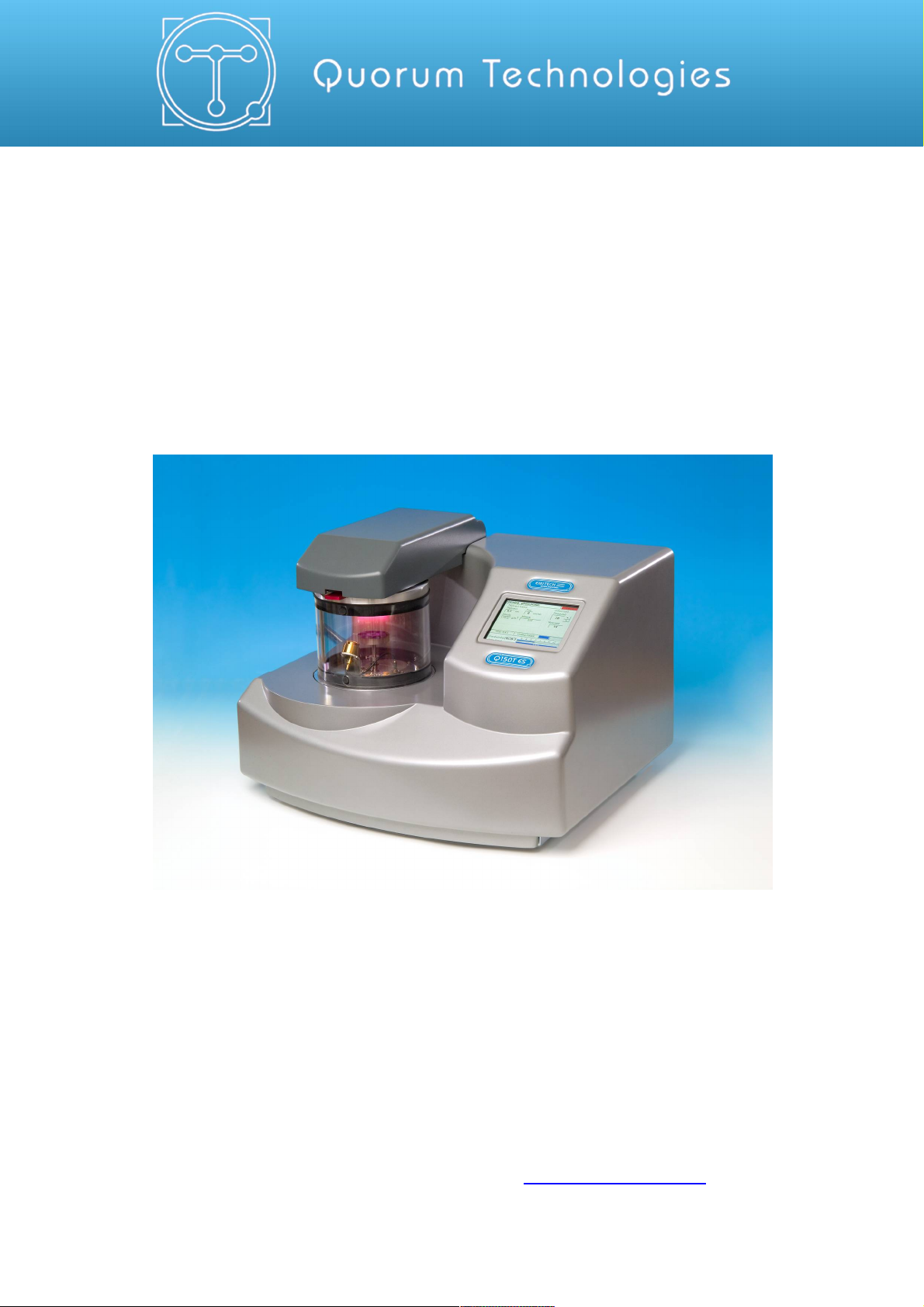
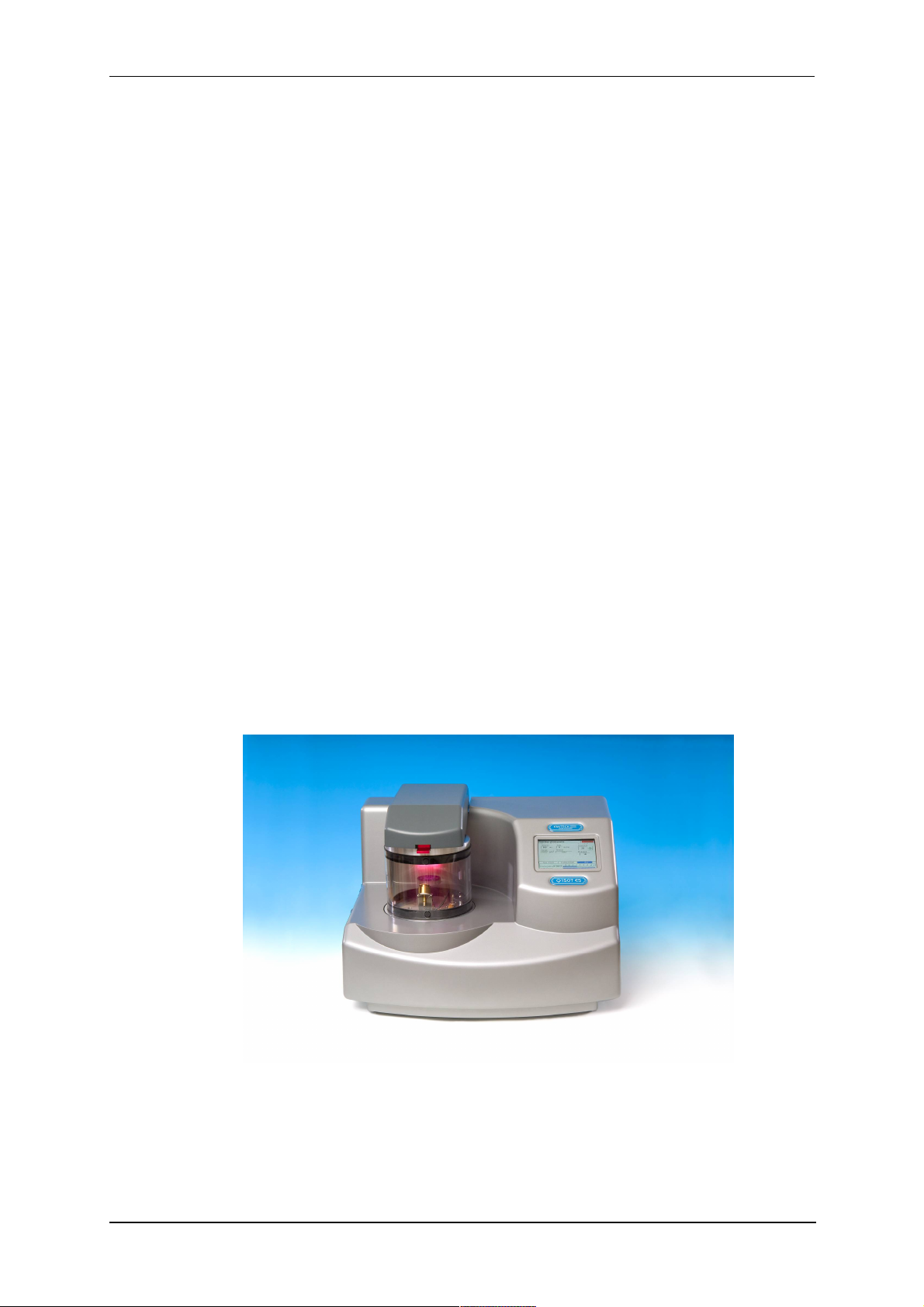
The Q150T system is a versatile sputter coater/turbo evaporator (see Figure 1-1) for
preparing specimens for examination by electron microscopy.
With a comprehensive selection of easily interchanged inserts and sample stages, the
Q150T can be used to:
Sputter coat samples using targets such as Chromium or Gold.
Evaporate support films and replicas for TEM and X-Ray analysis and conducting
coatings for SEM using 3mm or 6mm carbon rods or cords.
Evaporate metals upwards or downwards from a wire basket or molybdenum boat
arrangement.
Clean aperture strips.
There are three models in the Q150T range:
Q150T S Sputter coater version only.
Q150T E Carbon/metal evaporation version only.
Q150T ES Combined system with interchangeable inserts for sputter coating or
carbon/metal evaporation.
The instrument is fully adaptable to a wide range of specimens and offers easy loading
and unloading of samples. The changeover between sputtering and evaporation inserts
is simple. The system is fully automated with a user defined profile controlling the
pumping sequence, preheating, outgassing, the time and number of evaporation/sputter
bursts, and the current used during the process.
The Q150T can be fitted with a film thickness monitor (FTM), which measures the
coating thickness on a crystal in the chamber, to control the coating applied to the
sample. For example, the Q150T can automatically terminate a coating cycle when the
required thickness has been achieved.
Figure 1-1. Front view of the Q150T
The Q150T features a turbo molecular pump backed by a rotary vacuum pump and
controlled by the instrument throughout the fully automatic coating cycle.
The system is fitted with a vacuum shutdown system allowing the instrument to be
pumped down and switched off, with the chamber left under vacuum.
10473 - Issue 5 8 Q150T - Instruction Manual

1.2 Sputter Coating
Sputter Coaters are used in Scanning Electron Microscopy to provide an electrically
conductive thin film representative of the surface topography of the specimen to be
viewed, such films inhibit 'charging', reduce thermal damage, and enhance secondary
electron emission.
The Q150T S and Q150T ES employ a magnetron sputter target assembly. This
enhances the efficiency of the process using low voltages and giving a fine-grain (order
of 0.5nm Cr grain size), cool sputtering. The unit features a rotating sample table
ensuring even depositions (typically 5nm). It uses standard targets, avoiding the
necessity of special large profile targets. The instrument is fitted with a 57mm diameter
quick-change target (the sample chamber is 165mm in diameter) giving optimum
consumable cost performance. Alternative target materials are available.
A shutter assembly is fitted as standard, which allows sputter cleaning of oxidising
targets.
1.3 Carbon Coating
Carbon films, because of their mechanical stability, good electrical conductivity, and low
background signal are commonly used to prepare samples for Electron Microscopy
(EM).
Thin films of about 5 nm (50A) are used for particle support and as an isolating layer in
autoradiography. Thicker films are used in Scanning Electron Microscopy (SEM) also for
support, in addition to coating for X-Ray Microanalysis. In general, there is a need for all
these films to be fine grain, even coating, with uniform and reproducible film thickness.
The most common form of deposition is from resistance heated carbon rods. The rods
are shaped to achieve high current density with sufficient temperature to cause
evaporation. Carbon filaments can also be used, which at high temperature burn quickly,
from which has evolved the terminology: Carbon 'Flash' Evaporation. The resulting short
coating times and reduced total power input distinguishes it from the somewhat longer
process of carbon rod evaporation.
Q150T E and ES models feature a multi-change head system for Carbon rod, Carbon
fibre and metal evaporation.
Q150T Sample Preparation System
1.4 Metal Evaporation
By vaporizing a metal film onto a sample, it is possible to enhance the topographic detail
for high resolution analyses by TEM or SEM. This technique is particularly useful in the
analysis of biological specimens. The metal evaporant, usually a wire of, for example,
platinum or gold, is heated and vaporised by a filament (typically made of tungsten).
For downwards evaporation, evaporants usually in the form of wire: e.g gold, platinum,
aluminium, etc are placed directly onto the filament. For upwards evaporation, the
evaporant is placed in a ‘boat’ (typically made of molybdenum or tungsten).
The Q150T E and ES can be configured for metal evaporation in an upwards or
downwards direction.
1.5 Aperture Cleaning
In its metal evaporation configuration, you can use a Q150T E or Q150T ES to clean
aperture strips and other electron microscope components. With the component placed
in a molybdenum boat, it can be heated to evaporate contaminants.
Q150T - Instruction Manual 9 10473 - Issue 5

Q150T Sample Preparation System
2 Installation
It is important that this equipment is installed by skilled personnel in accordance with
these instructions. Failure to do so may result in damage or injury. 'If in doubt - ASK'.
2.1 Pre-installation
Identify a suitable location for the unit:
Mount the unit on a bench or the recommended trolley. The total weight of the system
is 33.4 kg.
The environment should have an ambient temperature range of 15ºC to 25ºC in a
non-condensing relative humidity of not more than 75%.
Sufficient ventilation is required, and positioning should be out of direct sunlight.
The system is rated for continuous operation.
2.1.1 Required Services
Argon
Supply for sputtering should be N4.8 (Zero Grade) 99.998% purity capable of supplying
3 litres/min at 4 psi. The regulator should be set at 4 psi.
The system is supplied with 3m plastic tubing 3mm I.D. x 6mm O.D. from a quick
release connector on the rear of the unit. It is the customer’s responsibility to connect
this tube to the pressure regulator from the gas bottle or plant supply. Typically a system
will use approx. 0.2 litres of Argon for a 4 minute sputter cycle (plus up to 4 litres if argon
is also used for purging and venting).
If bottle supply is adjacent it can be isolated locally, if not or plant supply,
local isolation valves should be fitted.
Nitrogen
Supply for purging should be N4.8 (Zero Grade) 99.998% purity capable of supplying 3
litres/min at 4 psi. The regulator should be set at 4 psi.
The system is supplied with 3m plastic tubing 3mm I.D. x 6mm O.D. from a quick
release connector on the rear of the unit. It is the customer’s responsibility to connect
this tube to the pressure regulator from the gas bottle or plant supply. Typically a system
will use up to 4 litres when Nitrogen is used for purging and venting.
If bottle supply is adjacent it can be isolated locally if not or plant supply,
local isolation valves should be fitted.
Pressure Regulators are Customer Supply, Nitrogen is recommended for
Purging for Economy, Argon must be provided for Sputtering, it can also be
used for Purging in the event of Nitrogen purge gas not readily available.
Typical regulators suitable for Argon and Nitrogen are the C106X/2 series available
from BOC
http://www.boconline.co.uk/en/products-and-supply/specialityequipment/regulators/two-stage-regulators/c106x2-series/c106x-2-series.html
Electrical supply
90-240V, 50/60Hz, 1350VA, including pump.
Vacuum Pump
Pump No 3 complete with Vac. Hose & Oil Mist Filter 35 litre/min 2m³/hr.
10473 - Issue 5 10 Q150T - Instruction Manual

2.2 Unpacking
1. Remove the Instrument from its packing and place it in its operational position.
2. Carry out a visual inspection to check for any signs of transit damage.
3. Remove the Accessories Pack, and check contents against Q150T Accessories
Pack shipping list.
4. Ensure that all areas of the Instrument are free of loose packaging material.
Check specifically the instrument chamber, glass cylinder, and gaskets. (Do not
use vacuum grease on gaskets).
5. If your unit includes a vacuum pump, carry out preliminary checks in accordance
with the manufacturer’s recommendations.
Q150T Sample Preparation System
CAUTION
Don’t try to lift the unit by yourself: it weighs 33.4kg. Get
someone to help you move it.
CAUTION
Do Not attempt to lift the lid from the chamber. Unlatch the grey
top cover and remove the 2 transit screws retaining the top plate
assembly. The set screw and the transit plate should be retained
with the instrument accessories in case further transit of the
instrument is necessary.
If you are intending to use an existing or alternative vacuum pump, and
have any difficulty with these connections, please contact our technical
support.
Q150T - Instruction Manual 11 10473 - Issue 5
2.3 Connections
Installation consists of the following steps:
Connect gas supplies (see below).
Make electrical connections (see page 13).
Connect the vacuum pump (see page 15).
Install the sample stage (see page 16).
If you want to install a different insert than that supplied with your instrument, please see
page 54. If you have ordered a Q150T ES, the instrument will be fitted with the sputter
insert, unless you have specifically requested another configuration.
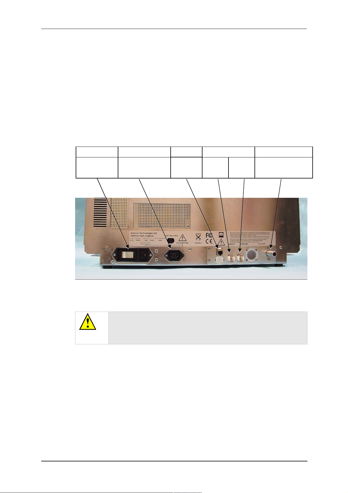
Figure 2-1 shows the location of connectors and switches on the rear panel of the
Q150T.
Power inlet with
integral On/Off
rocker switch
Q150T Sample Preparation System
Power supply for rotary
pump allowing control by
instrument.
Network
connection
GAS INLETSPUMP OUTLETPOWER INLET VACUUM CONNECTIONAUX
Argon
0.3bar
(4psi)
1
Nitrogen
0.3bar
(4psi)
2
Rotary Pump Vacuum
connection
Figure 2-1. Q150T Rear Panel
(1). S versions only
(2). If using air instead of Nitrogen, fit filter part no. 12842 see “Gas Connections”,
below.
WARNING
UNDER NO CIRCUMSTANCES SHOULD ANY OTHER
CONNECTIONS OR OUTLETS/INLETS BE USED FOR ANY OTHER
EQUIPMENT OR SERVICES.
10473 - Issue 5 12 Q150T - Instruction Manual
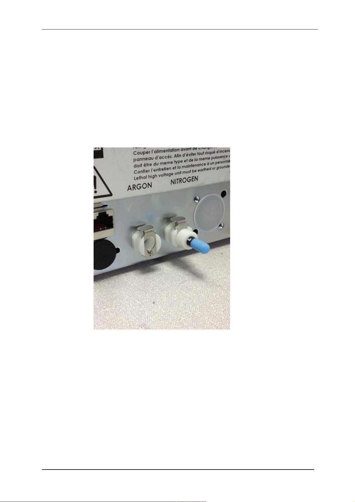
2.3.1 Gas Connections
1. Connect a suitable argon supply at a regulated input of 0.3bar (4psi) to the quick
connect Argon gas connector on the rear panel (see Figure 2-1. If you prefer, you
can use argon for both process and purge supplies.(recommended if coating with
oxidising targets). To do so, install a 'T' piece across both gas inlets.
2. Connect a suitable nitrogen supply at a regulated input of 0.3bar (4psi) to the
quick connect Nitrogen connector on the rear panel. Air may be used in place of
nitrogen for venting (not recommended for oxidising targets) but it is important to
fit the filter (part no. 12842) to prevent ingress of dust (see Figure 2-2). Failure to
connect this filter could prevent the system venting at the end of a cycle.
Connectors are push-fit and will 'snap' into a locked position. To release a connector,
depress the metal tongue.
Q150T Sample Preparation System
Figure 2-2. Gas connectors with filter (part no. 12842) fitted to purge gas inlet
Q150T - Instruction Manual 13 10473 - Issue 5
Q150T Sample Preparation System
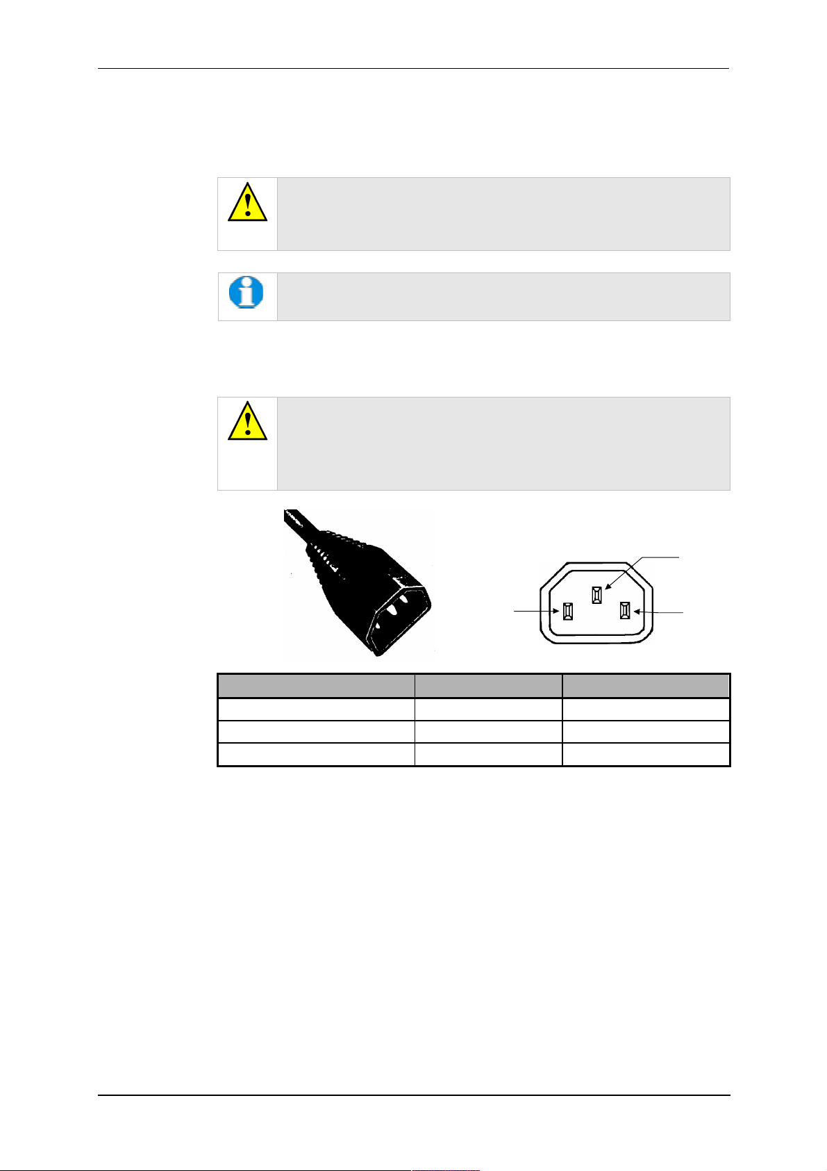
2.3.2 Electrical Connections
1. Connect the instrument to a suitable earthed single-phase ac supply using the
supplied cable. The lead should be fitted with the appropriate plug for your
country. Ensure the plug is firmly located.
WARNING – EARTH CONNECTION
This Equipment must be Earthed and fitted with the correct lead for the
country of operation. This Equipment is normally supplied from 3 pin
supply including Earth.
For fuse information, refer to Table 32.
2. Connect the rotary pump power lead to the Pump Output connector on the rear
panel (see Figure 2-3). If the rotary pump has its own switch, ensure that this is
set to the ‘On’ position.
WARNING – PUMP OUTPUT
Check that the Power Output is suitable for the rotary pump. The Pump
Output is intended for connection to the pump supply only and provides
the electrical supply voltage at a maximum of 4 Amps.
PIN UK AND EUROPE U.S.A. AND CANADA
Pin 1 ( Live or Hot) Brown Black
Pin 2 ( Earth ) Green / Yellow Green
Pin 3 ( Neutral) Blue White
Figure 2-3. Power outlet lead wiring
2.3.3 Aux Network Connection
To link the Q150T to your network, use a standard CAT5/5e cable with RJ45 network
connectors to connect the AUX Network port directly to your computer’s network port or a
network hub/switch.
Pin 1
Live
Pin2
Earth
Pin 3
Neutral
10473 - Issue 5 14 Q150T - Instruction Manual

Q150T Sample Preparation System
2.3.4 Vacuum Connections
1. If you are using an existing or alternative vacuum pump, and have any difficulty
with connections, please ask for advice.
2. If the instrument is NOT going to be vented into an extraction system, fit an Oil
Mist Filter with metal adapter to the outlet of the vacuum pump. Please refer to
the manufacturer’s instructions.
3. Ensure that the vacuum pump is filled with the correct oil.
4. If the vacuum pump is fitted with an on/off switch, ensure that it is set to the 'on'
position to allow the instrument to control its power supply.
5. Connect the flexible vacuum hose to the spigot on the rear panel using the hose
clip provided. This is a push-on fit to the Instrument. Ensure that this is firmly in
place to the full length of the spigot.
A rotating vacuum spigot is available for more convenient hose
connection in installations where the instrument is to be located close
to a back wall (see page 69).
Q150T - Instruction Manual 15 10473 - Issue 5
Q150T Sample Preparation System
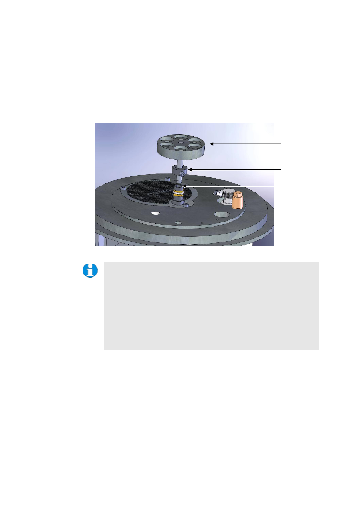
2.3.5 Fitting the Standard Stage
The Q150T is supplied with a standard stage (10067). For installation instructions for
other stages, see page 54. To install the standard stage:
1. Ensure that the instrument is vented and in standby mode.
2. Open the top cover fully so it rests against its backstop.
3. If there is already a stage in place, remove it by lifting carefully upwards.
4. Fit the standard stage by locating its shaft into the top of the stage rotation drive
spigot protruding from the baseplate and with a twisting motion pushing it gently
down until the collar around the shaft rests on top of the drive spigot (see below).
Standard stage
Height-adjusting
collar
Rotation drive
spigot
Figure 2-4. Fitting the standard stage
You can adjust the height of the stage above the base plate by moving the
collar up or down the shaft. Unfasten the M3 screw with a hexagonal key,
slide the collar to the required position and retighten the M3 screw.
For maximum distance between the stage and the target, remove the collar
so that the underside of the stage rests on the top of the drive spigot. To
reduce the distance between the stage and target, fit the stage with the
alternative long shaft (10214 – supplied with stage).
When using small 1/8” pin stubs, it is advisable to unscrew the stage and fit it
upside down for easy access to the stub.
Note that the Q150T’s default tooling factors are based on a stage
height of 60mm from the base plate.
2.3.6 Optional Connections
For full connection details of optional units, where provided, please refer to separate
instructions. Any other connections on the rear panel not listed are for common
manufacturing and are not available for this instrument.
10473 - Issue 5 16 Q150T - Instruction Manual
Q150T Sample Preparation System
3 Operation
This chapter describes the basic operation of the Q150T. For more advanced use,
please see Working with Profiles on page 21 and Application Guidelines on page 28.
3.1 Switching On for the First Time
1. Ensure that you have completed the installation as described in the previous
sections.
2. Switch the instrument on using the rocker switch located on the rear panel. The
front panel LCD display should illuminate and show the initialising message.
3. Once the instrument hardware and software has initialised, the standby screen is
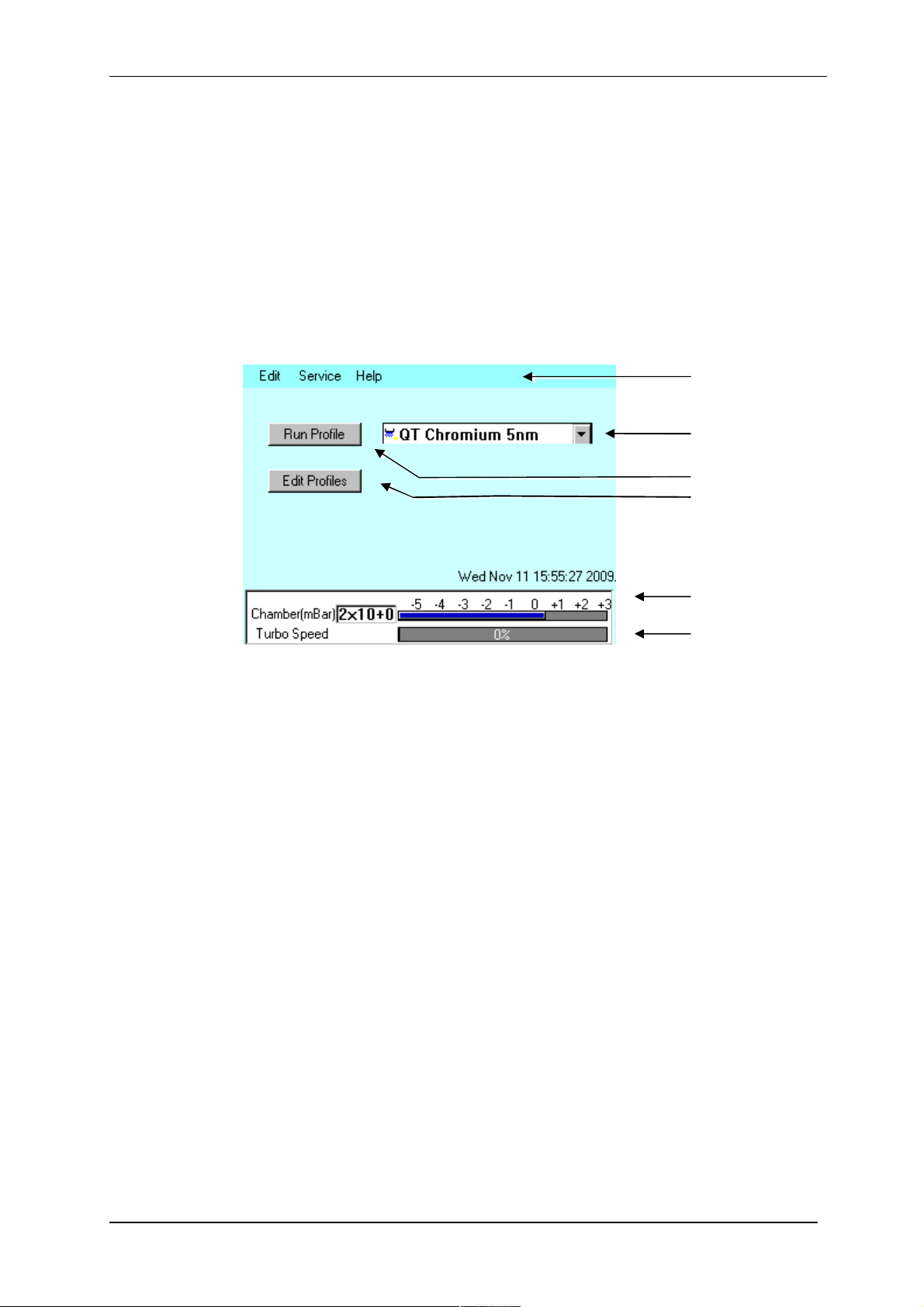
displayed (see Figure 3-1).
Menu bar
Profile list box
Run Profile button
Edit Profiles button
Figure 3-1. Standby screen
3.1.1 The Standby screen
The Standby screen has three main parts:
A menu bar with Edit, Service and Help categories (see page 42).
Run Profile and Edit Profile buttons and a profile selector. Operate the instrument
simply by selecting a profile and tapping on the Run Profile button.
Pumping/vacuum information display: Chamber pressure reading and meter, and a
turbo speed indicator.
Chamber pressure
reading and meter
Turbo pump speed
meter
Q150T - Instruction Manual 17 10473 - Issue 5
Q150T Sample Preparation System
3.2 Running a Profile
Before you can run a profile, ensure you have:
Completed the installation as described on page 10.
Switched on the instrument (see section 17).
Loaded a sputter/coating target or loaded an evaporation source (see page 54).
To run a profile:
1. Load your sample onto the center of the sample stage.
2. Close the top cover assembly and press it firmly down to secure the latch.
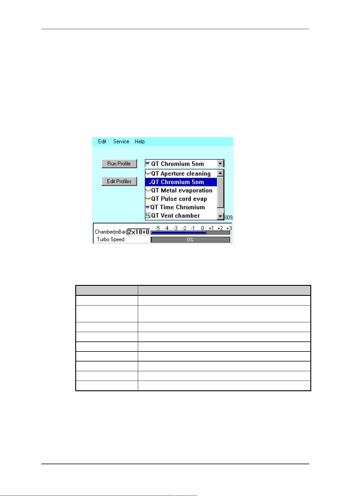
3. Tap on the down arrow button to open the dropdown list of profiles (see Figure
3-2).
Figure 3-2. Selecting a profile
4. The Q150T has several default profiles for common tasks as shown in Table 1.
Tap on the name of the profile you want to run.
Table 1 Q150T Default Profiles
PROFILE NAME PURPOSE
QT Time Chromium Sputter coating run using Chromium target (see page 28)
QT Chromium 5nm*
QT Metal evaporation Coating using metal evaporator (see page 31)
QT Aperture cleaning Default profile for aperture cleaning (see page 40)
QT Pulse rod evap Evaporation using carbon rods (see page 32)
QT Pulse cord evap Evaporation using carbon cord (see page 32)
QT Controlled pulse Evaporation using FTM termination of carbon cord (see page 32)
QT Vent chamber Vent sample chamber
QT Vacuum shutdown Pumps chamber to 1mBar to allow shutdown under vacuum
* Profile only present on systems equipped with FTM.
Sputter coating run using Chromium target terminated by FTM at a
coating thickness of 5nm (see page 28)
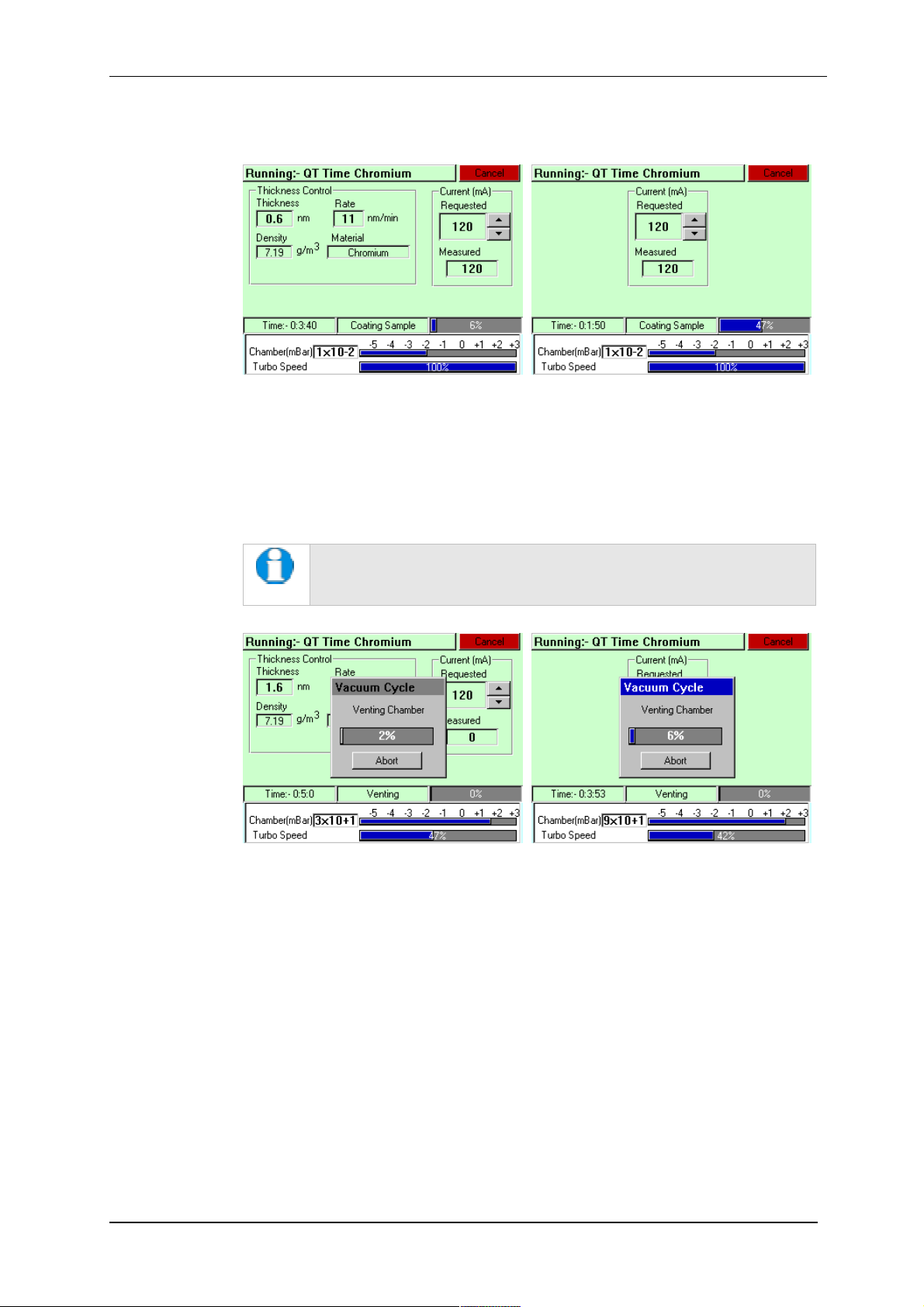
5. Tap on the Run Profile button. The Q150T starts pumping the sample chamber.
The progress of the run is shown through a series of on-screen messages (Figure
3-3).
10473 - Issue 5 18 Q150T - Instruction Manual
Q150T Sample Preparation System
Figure 3-3. A run in progress: with FTM installed (left) and without FTM (right).
6. If you want to stop a run while it is in progress, tap on the Cancel button.
7. At the completion of the run, the Q150T begins to vent the chamber (see Figure
3-4). If you want to record thickness control or current information, make a note of
it now. When the chamber has been vented, the display reverts to the standby
screen (see Figure 3-1).
Future versions of the Q150T software will allow logging of thickness
control and profile parameters through the instrument’s network
communication capabilities.
Figure 3-4. Venting the chamber: with FTM installed (left) and without FTM
(right).
8. When the chamber has been completely vented, the display reverts to the standby
screen. You can now remove your sample and set up another run.
Q150T - Instruction Manual 19 10473 - Issue 5
3.3 System Settings
The operation of the Q150T is controlled by its profile parameters. However, there are
several system parameters, which can be changed without altering the profile. A systemset parameter overrides the corresponding setting specified in the active profile. You can
make the new setting apply just to runs using the active profile or to all runs, irrespective
of the choice of profile.
To change a system parameter:
1. Open Profile Editor: from the standby screen, tap on the Edit Profile button or
choose Edit | Profiles from the menu bar.
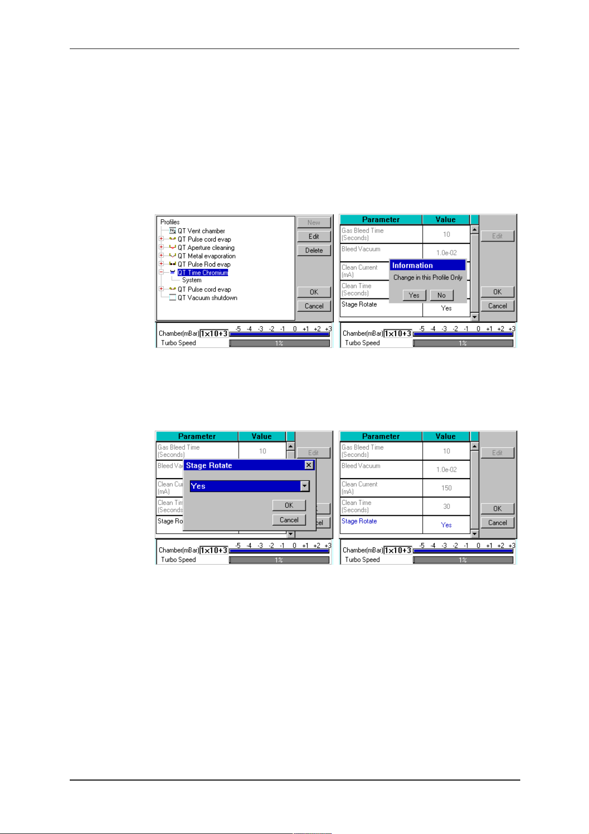
2. Tap on the + sign to the left of the currently active profile (see Figure 3-5 - left).
Q150T Sample Preparation System
Figure 3-5. Listing system properties for a profile
3. Tap on System. System Property Editor is displayed (see Figure 3-5 - right).
4. You are prompted to confirm whether the changes are to be applied to runs using
this profile only or to all runs. Tap on the Yes button to apply changes to the active
profile only, or No to apply the change to all runs.
Figure 3-6. Changing the Stage Rotate system property
5. Tap on the value of the system property you want to change (in this case, Stage
Rotate). Amend the setting as required and confirm the change by tapping on the
OK button. Tap on the Cancel button to cancel any change (see Figure 3-6).
6. Altered system parameters are shown with blue text.
7. Tap on the OK button to exit the System Property Editor.
10473 - Issue 5 20 Q150T - Instruction Manual
Q150T Sample Preparation System
4 Working with Profiles
The operation of the Q150T is controlled by a profile. This describes the sequence of
operations in sputter coating or evaporation cycles. You can also create profiles to carry
out simple operations such as pumping or venting the sample chamber. Many of the
basic operations such as pumping, outgassing or venting the chamber occur
automatically as does the sequence in which they occur.
The Q150T is supplied with several default profiles to perform the basic and most
common operations (see Table 1). To make your own profiles, customised for your
specific applications, you can:
Edit an existing default profile
Create a new profile
4.1 Editing the Active Profile
To edit the profile currently selected on the standby screen, tap on the Edit Profile
button. The editable parameters of the selected profile are displayed (see Figure 4-4).
Now refer to the Editing Profile Parameters section on page 24.
4.2 Profile Editor
To create, edit or delete any profile:
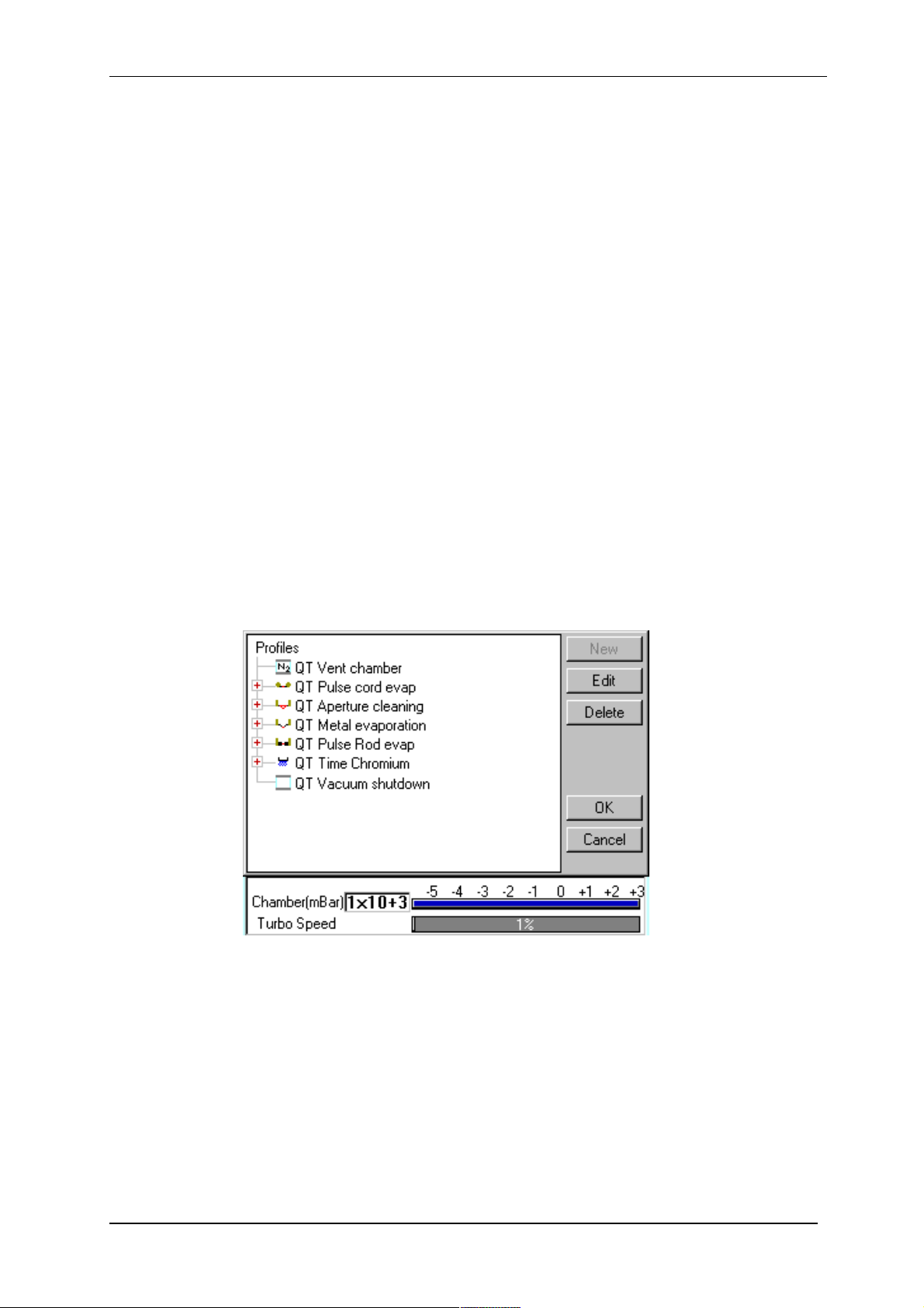
1. Select Edit | Profiles from the menu bar. Profile Editor is displayed (see Figure
4-1).
Figure 4-1. Profile Editor
Q150T - Instruction Manual 21 10473 - Issue 5
Q150T Sample Preparation System
In its main window, Profile Editor lists all existing profiles. To the left of each
profile name, an icon denotes the type of profile (see Table 2).
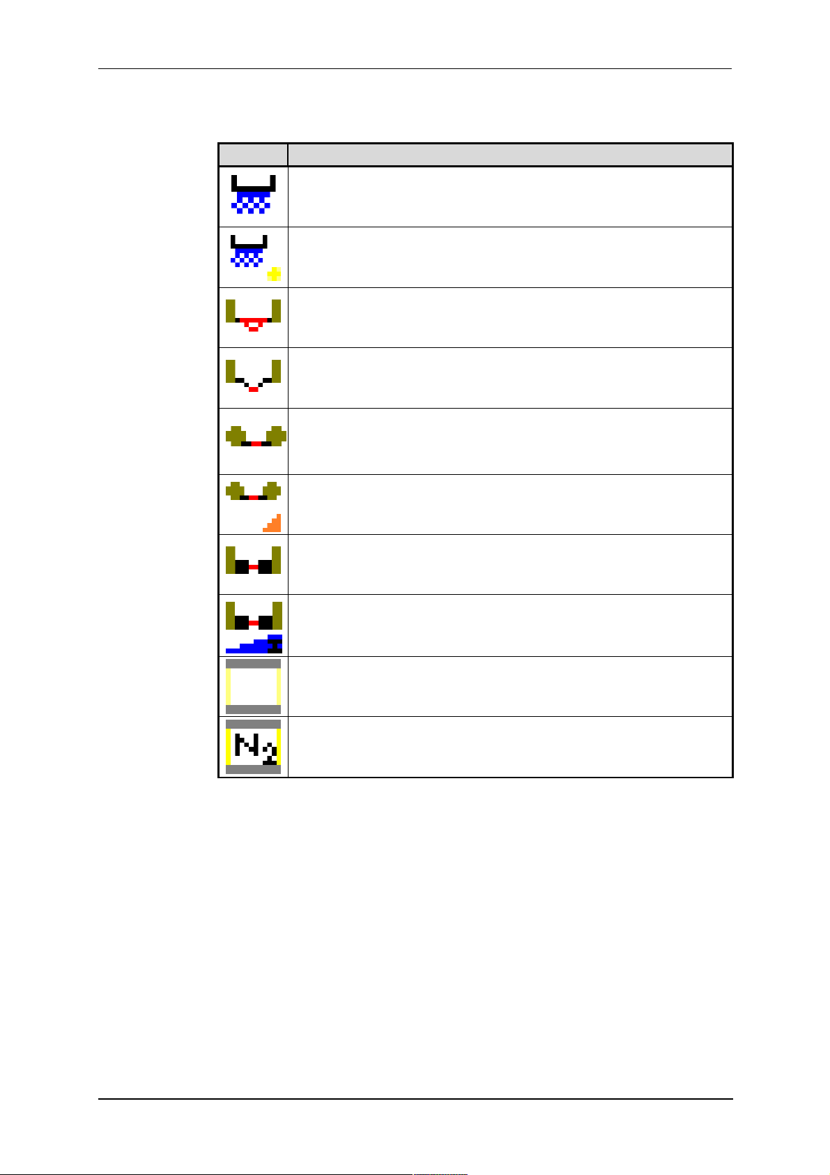
Table 2 Profile icons
Icon Profile/Process Type
Timed sputter (see Table 24)
FTM terminated sputter (see Table 24)
Aperture cleaning (see Table 29)
Metal evaporation (see Table 28)
Pulse cord evaporation (see Table 25)
QT Controlled pulse cord (see Table 26)
Pulse rod evaporation (see Table 25)
Ramped carbon
Vacuum shutdown (see Table 30)
Vent chamber
2. Tap on one of the buttons on the right side of the editor:
a. To create a new profile, tap on the New button (see Creating a new
profile).
b. To edit a profile, tap on its name and then tap on the Edit button. The
Profile’s parameters are displayed (now see Editing Profile
Parameters)
c. To delete a profile, tap on its name and then tap on the Delete button.
10473 - Issue 5 22 Q150T - Instruction Manual
Q150T Sample Preparation System
4.2.1 Creating a New Profile
To create a new profile:
1. With Profile Editor displayed, tap on Profiles at the root of the profile ‘tree’.
2. Tap on the New button.
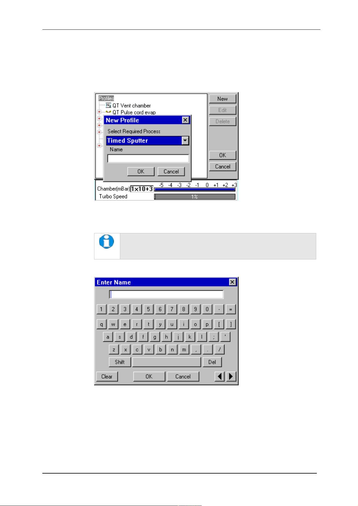
3. The New Profile dialog box is displayed (see Figure 4-2).
Figure 4-2. Creating a new profile
4. Choose the type of profile you want from the Select Required Process drop-down
list).
See Table 2 for a list of all the available processes. Note that the
processes listed are different for Q150T E, Q150T S and Q150T ES
models.
5. Enter a name for the profile: tap in the Name field to display the on-screen
keyboard (Figure 4-3) in the Enter Name dialog box.
Figure 4-3. Entering a new profile name
6. Tap on the OK button to confirm the changes to the profile. Alternatively, tap on
the Cancel button to close the dialog box without creating a new profile.
7. The new profile is created using the default settings for the chosen process type.
8. Now refer to the Editing Profile Parameters section, below.
Q150T - Instruction Manual 23 10473 - Issue 5
Q150T Sample Preparation System
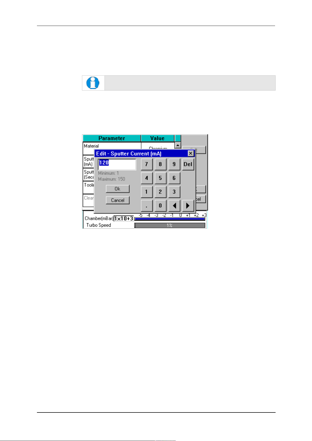
4.2.2 Editing Profile Parameters
1. To edit a profile, tap on its name in Profile Editor and then tap on the Edit button.
A table showing the profile’s parameters is displayed.
2. To edit a parameter, tap on its value (it is then highlighted in blue) and then tap on
the Edit button.
If a parameter is shown in grey text, you do not have the necessary
user privileges to edit it. See page 49 for details.
3. Change the value as required (see Figure 4-4). The instrument displays a dialog
box for editing purposes, with either a numeric keypad or keyboard as required.
The dialog box also shows the allowed values for the parameter.
4. Click on the OK button to confirm the change or on the Cancel button to restore
the previous value.
Figure 4-4. Editing Profile Parameters
5. Edit other parameters as required.
6. On the Profile window, click on the OK button to confirm the changes to the profile
or on the Cancel button to restore the previous values.
To see a list of the parameters used in profiles see page 78.
10473 - Issue 5 24 Q150T - Instruction Manual
4.3 Materials
The software contains a database of the most common elements and alloys used in
sputtering and evaporation applications (see Table 3). The choice of material is the first
parameter in a Sputter Coating profile. The embedded density information is used to
calculate film thickness.
Material
Aluminium 2.70
Carbon 2.25
Titanium 4.54
Chromium 7.19
Nickel 8.90
Copper 8.96
Silver 10.50
Palladium 12.02
Gold / Palladium (Au/Pd) (80:20 mix) 17.86
Tungsten 19.30
Gold 19.32
Platinum / Palladium (Pt/Pd) (80:20 mix) 19.56
Platinum 21.45
Iridium 22.40
User Defined allowable range 1.00 - 23.00
Q150T Sample Preparation System
Table 3 Materials and their density
Density
3
g/cm
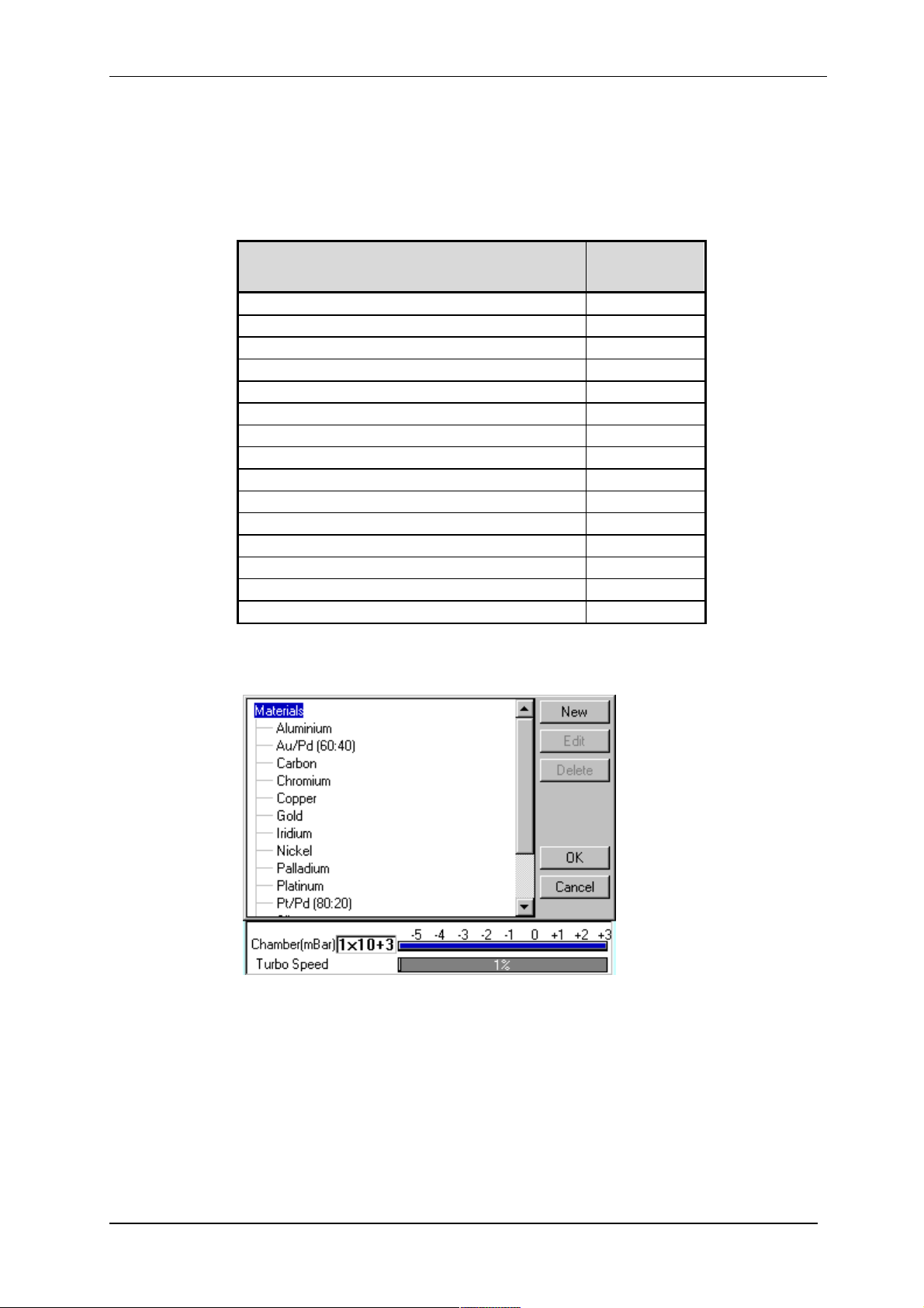
To create, edit or delete a new entry in the material database, select Edit | Materials
from the menu bar. Materials Editor is displayed (see Figure 4-5).
Figure 4-5. Materials Editor
Materials Editor lists all the existing materials in the Q150T database and allows you to
add new materials or edit existing material definitions.
Q150T - Instruction Manual 25 10473 - Issue 5
Q150T Sample Preparation System
4.3.1 Creating a New Material
To create a new material:
1. Select Edit | Materials from the menu bar. Material Editor is displayed (see
Figure 4-5).
2. Tap on Materials at the root of the material ‘tree’.
3. Tap on the New button. The New Material dialog box is displayed.
4. Enter a name for the profile: tap in the Name field to display the on-screen
keyboard (Figure 4-6) in the Enter Name dialog box.
5. Tap on the OK button to confirm the changes to the material. Alternatively, tap on
the Cancel button to close the dialog box without creating a new material.
6. The new material is created using the default settings for the chosen process type.
7. Now refer to the Editing Material Parameters section.
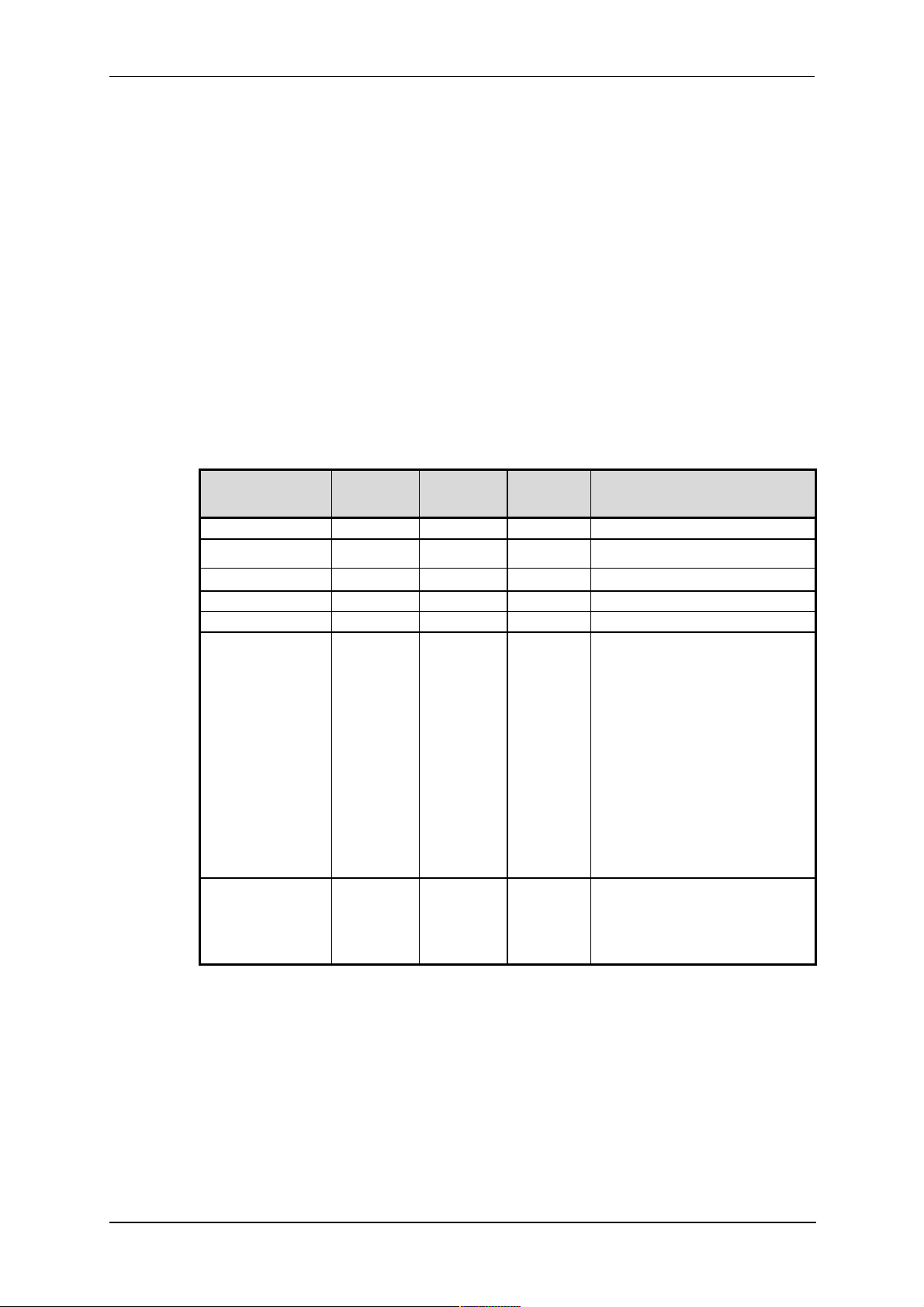
4.3.2 Editing Material Parameters
Each material is defined by the parameters shown in Table 4:
Table 4 Material parameters
Name Default
Value
Density 10 1 30
Material Type oxidising noble oxidising
Minimum
Value
Maximum
Value
Comment
Sputter Current 50 1 150
Clean Current 150 100 150
Material Tool 0.1 10
Sputter cleaning
mode*
Sputter stop
cleaning at (Volts)*
* Displayed for information only. Changes if required will need to be carried out by a Quorum
agent.
Timed Specifies how the material will be
cleaned. Options are:
Timed
Continuous sputter for fix time.
Pulse above
Cycle plasma until target voltage
is above that specified in
Sputter stop cleaning at
Pulse below
Cycle plasma until target voltage
is below that specified in
Sputter stop cleaning at
Only used during pulse cleaning
of target.
250 90 600 Target voltage that needs to be
achieved before cleaning is
completed and the coating starts.
Only used during pulse cleaning
of target.
10473 - Issue 5 26 Q150T - Instruction Manual
Q150T Sample Preparation System
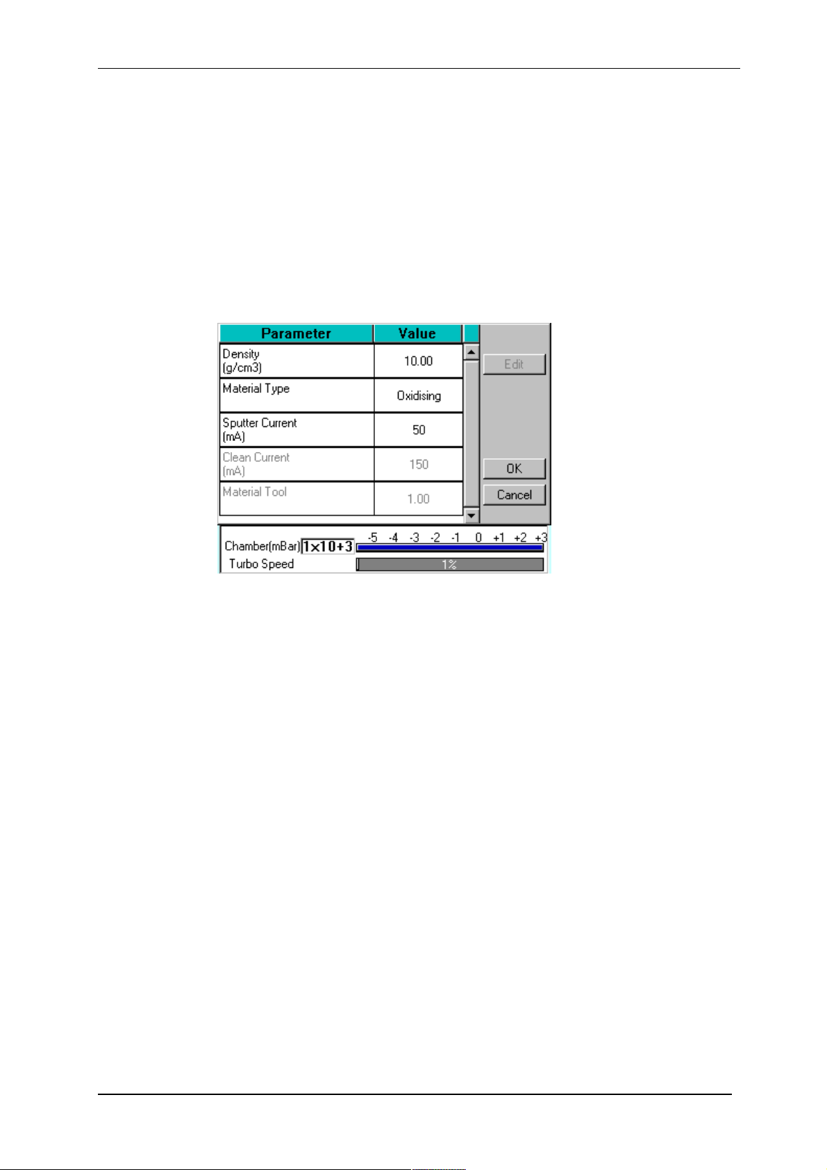
To edit a material:
1. Tap on the material’s name and then tap on the Edit button.
2. To edit a parameter, tap on its value (it is then highlighted in blue) and then tap on
the Edit button.
3. Change the value as required. The instrument displays a dialog box for editing
purposes, with either a numeric keypad or keyboard as required. The dialog box
also shows the allowed values for the parameter.
4. When you edit a value, tap on the OK button to confirm the change or on the
Cancel button to restore the previous value.
5. Edit other parameters as required.
6. Back in the Material Editor, tap on the OK button to confirm the changes to the
material or on the Cancel button to restore the previous values.
Figure 4-6. Material Parameters
4.3.3 Deleting a Material
To delete a material, tap on its name and then tap on the Delete button.
Q150T - Instruction Manual 27 10473 - Issue 5

Q150T Sample Preparation System
5 Application Guidelines
This section describes the QT processes and their typical applications.
5.1 QT Timed Sputter
Suitable for the following applications:
SEM coatings for tungsten emission SEM.
High resolution SEM coatings for field emission SEM.
General thin film coatings.
Target materials: Au, Au/Pd or Pt
5.1.1 Tungsten SEM work
For this type of work, the aim is to achieve a typical thickness of 10-20nm from a gold
target. Figure 9-1 shows the deposition graph for gold. With a current of 20mA, a
deposition rate of 20nm/minute is typically achieved (assuming that the sample height is
set to the default height of 60mm and the vacuum is 1x10⁻²mBar).
To achieve a gold coating of 10nm create a new profile based on QT Timed Sputter: The
default Material setting is Au.
Edit the current to 25 mA.
Set the time to 30 seconds.
If necessary adjust the time or current slightly to modify the thickness.
5.1.2 High resolution SEM coatings for field emission SEM
Generally, the recommended target materials are Cr or Ir and the objective is to
generate a coating thickness of 5-10 nm.
The deposition graph using a Cr target is shown in Figure 9-2. With a current of 100mA,
a deposition rate of 20nm/minute is typically achieved (assuming that the sample height
is set to the default height of 60mm and the vacuum is 1x10⁻²mBar)
To achieve a Cr coating of 10nm, create a new profile based on QT Timed Sputter:
Set the material to Cr.
Edit the current to 100 mA.
Set the time to 30 seconds.
If necessary adjust the time or current slightly to modify the thickness.
10473 - Issue 5 28 Q150T - Instruction Manual
 Loading...