

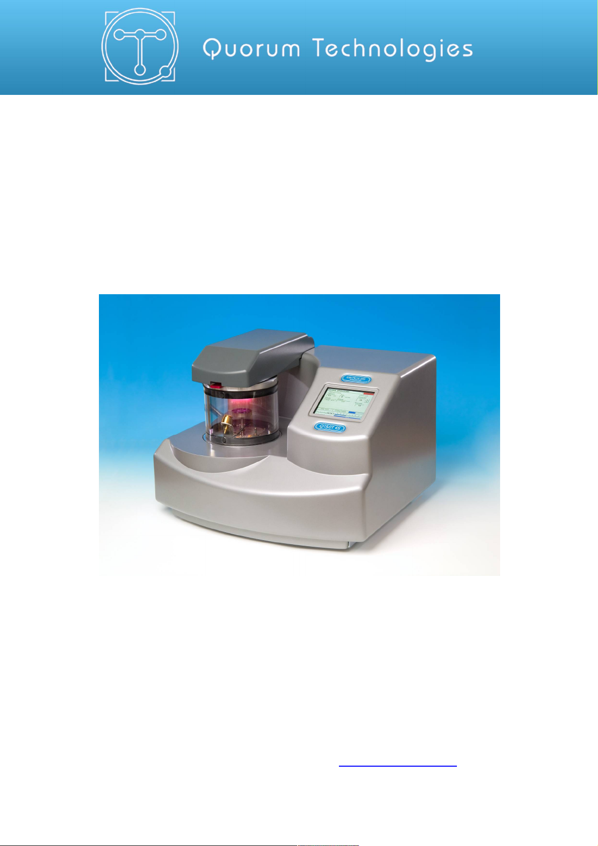
Q150T S/E/ES
Sample Preparation System
Instruction Manual
10473
Issue 5
For technical and applications advice plus our on-line shop for
spares and consumable parts visit www.quorumtech.com
Quorum Technologies Ltd.
Judges House
Lewes Road
Laughton
East Sussex
BN8 6BN
Tel: +44(0) 1323 810981
Email: mailto:sales@quorumtech.com
Web : http://www.quorumtech.com
For technical and applications advice plus our on-line shop for spares and consumable
parts visit www.quorumtech.com
Issue Date Details Revised By
1 03/06/10 Initial Issue SRM
2 20/08/10 Glow discharge updates SRM
3 31/01/12 Ramped profile, Aperture cleaning update, Aluminium coating SRM
4 04/02/13 Gas supply, rod shaping instructions, outgassing SRM
5 16/07/14 Addition of controlled pulse carbon and other corrections SRM
Disclaimer
The components and packages described in this document are mutually compatible and
guaranteed to meet or exceed the published performance specifications. No performance
guarantees, however, can be given in circumstances where these component packages are used
in conjunction with equipment supplied by companies other than Quorum Technologies Ltd.
www.quorumtech.com
Quorum Technologies Limited Company No. 04273003
Registered Office: Unit 19, Charlwoods Road, East Grinstead, West Sussex, RH19 2HL, UK

Q150T Sample Preparation System
Contents
Section Contents
1 Introduction.......................................................................................................... 8
1.1 General Description .........................................................................................8
1.2 Sputter Coating................................................................................................ 9
1.3 Carbon Coating................................................................................................ 9
1.4 Metal Evaporation ............................................................................................9
1.5 Aperture Cleaning ............................................................................................9
2 Installation.......................................................................................................... 10
2.1 Pre-installation............................................................................................... 10
2.1.1 Required Services .......................................................................................................10
2.2 Unpacking...................................................................................................... 11
2.3 Connections................................................................................................... 12
2.3.1 Gas Connections ........................................................................................................ 13
2.3.2 Electrical Connections.................................................................................................14
2.3.3 Aux Network Connection.............................................................................................14
2.3.4 Vacuum Connections ..................................................................................................15
2.3.5 Fitting the Standard Stage...........................................................................................16
2.3.6 Optional Connections ..................................................................................................16
3 Operation............................................................................................................ 17
3.1 Switching On for the First Time ...................................................................... 17
3.1.1 The Standby screen ....................................................................................................17
3.2 Running a Profile ...........................................................................................18
3.3 System Settings............................................................................................. 20
4 Working with Profiles......................................................................................... 21
4.1 Editing the Active Profile ................................................................................21
4.2 Profile Editor ..................................................................................................21
4.2.1 Creating a New Profile ................................................................................................23
4.2.2 Editing Profile Parameters...........................................................................................24
4.3 Materials........................................................................................................ 25
4.3.1 Creating a New Material ..............................................................................................26
4.3.2 Editing Material Parameters ........................................................................................ 26
4.3.3 Deleting a Material....................................................................................................... 27
5 Application Guidelines ...................................................................................... 28
5.1 QT Timed Sputter .......................................................................................... 28
5.1.1 Tungsten SEM work.................................................................................................... 28
5.1.2 High resolution SEM coatings for field emission SEM ................................................28
5.1.3 Aluminium thin film...................................................................................................... 29
5.2 QT FTM Terminated Sputter........................................................................... 30
5.2.1 High resolution SEM coatings for field emission SEM ................................................30
5.2.2 General thin film coatings ............................................................................................ 30
5.3 Metal Evaporation .......................................................................................... 31
5.3.1 How to achieve a 20nm gold coating ...........................................................................31
5.4 Pulsed Cord Evaporation................................................................................ 32
5.4.1 How to create a 20nm carbon coating .........................................................................32
5.5 Controlled Pulse Cord Evaporation................................................................. 32
5.5.1 Using Controlled Pulse to create a 15nm coat or 2-3nm for EBSD ............................. 32
5.6 Pulsed Rod Evaporation................................................................................. 34
5.6.1 How to create a conductive layer for SEM................................................................... 34
5.7 Ramped Profile .............................................................................................. 35
5.7.1 Carbon insert setup..................................................................................................... 35
5.7.2 The ramped current profile .......................................................................................... 36
5.7.3 Adjusting coating thickness.........................................................................................37
5.7.4 How to create a carbon support layer For TEM........................................................... 37
How to create a conductive carbon layer for SEM .................................................................... 38
5.8 Using Outgas Source options ......................................................................... 39
5.8.1 Setting Outgas Source options ...................................................................................39
5.8.2 Running Multiple Outgassing ......................................................................................39
5.9 Glow Discharge..............................................................................................40
5.9.1 Hydrophilisation ........................................................................................................... 40
5.9.2 Surface Cleaning......................................................................................................... 40
Q150T - Instruction Manual 3 10473 - Issue 5

Q150T Sample Preparation System
5.10 Aperture Cleaning .......................................................................................... 41
6 Instrument Management .................................................................................... 42
6.1 The Q150T Menus ......................................................................................... 42
6.2 Instrument Settings ........................................................................................ 43
6.2.1 Network .......................................................................................................................44
6.2.2 Generic Sputter ...........................................................................................................45
6.2.3 Vacuum....................................................................................................................... 46
6.2.4 Maintenance................................................................................................................47
6.2.5 Hardware..................................................................................................................... 48
6.3 User Management.......................................................................................... 49
6.3.1 Changing User Group .................................................................................................49
6.3.2 Managing User Groups ...............................................................................................50
6.4 Film Thickness Monitor ..................................................................................51
6.5 Setting the Date and Time.............................................................................. 51
6.6 Setting up a Network connection .................................................................... 52
6.6.1 Configuring a Firewall Exception for Windows Explorer.............................................. 52
6.6.2 Connecting the Q150 ..................................................................................................52
6.6.3 Network Troubleshooting ............................................................................................ 53
6.7 Process Logging ............................................................................................53
7 Accessories ........................................................................................................ 54
7.1 Sputter Insert .................................................................................................54
7.2 Carbon Rod Insert.......................................................................................... 56
7.2.1 Shaping Carbon Rods for Pulsed Evaporation............................................................57
7.2.2 Shaping Carbon Rods for Ramped Evaporation .........................................................58
7.3 Fitting the Carbon Fibre Insert ........................................................................ 58
7.4 Metal Evaporation Insert ................................................................................ 59
7.4.1 Installing a Wire Basket ..............................................................................................59
7.4.2 Installing a Molybdenum Boat for Aperture Cleaning...................................................59
7.4.3 Adapting the Insert for Upwards Evaporation..............................................................60
7.5 Glow Discharge Insert .................................................................................... 62
7.6 Rotacota Stage .............................................................................................. 64
7.7 Slide Stage ....................................................................................................65
7.8 102mm Stage and Gearbox ........................................................................... 66
7.9 Tilt Stage ....................................................................................................... 67
7.10 Film Thickness Monitor (FTM)........................................................................ 68
7.10.1 Replacing the FTM crystal ..........................................................................................68
7.11 Extended Height Cylinder ............................................................................... 69
7.12 Full Range Vacuum Gauge Assembly ............................................................69
7.13 Rotating Vacuum Spigot ................................................................................70
7.14 Emergency Stop Module ................................................................................ 71
7.15 Spares ........................................................................................................... 72
7.16 Other Accessories.......................................................................................... 73
8 Service and Maintenance................................................................................... 74
8.1 Maintenance ..................................................................................................74
8.2 Troubleshooting ............................................................................................. 75
8.3 Error Messages.............................................................................................. 75
9 Appendices......................................................................................................... 78
9.1 Profile Parameters .........................................................................................78
9.2 System Overrideable Parameters ................................................................... 83
9.3 Technical Specification................................................................................... 84
9.4 Sputtering Deposition Rate............................................................................. 85
9.5 Return of Goods............................................................................................. 88
9.5.1 General Introduction .................................................................................................... 88
9.5.2 Health and Safety Declaration ..................................................................................... 88
9.5.3 Despatch ..................................................................................................................... 88
9.5.4 Return Address: .......................................................................................................... 88
9.5.5 Declaration of Contamination Form ............................................................................. 89
10 Index ................................................................................................................... 90
10473 - Issue 5 4 Q150T - Instruction Manual

Q150T Sample Preparation System
List of Figures
Figure 1-1. Front view of the Q150T................................................................................................8
Figure 2-1. Q150T Rear Panel ......................................................................................................12
Figure 2-2. Gas connectors with filter (part no. 12842) fitted to purge gas inlet ............................13
Figure 2-3. Power outlet lead wiring............................................................................................... 14
Figure 2-4. Fitting the standard stage............................................................................................ 16
Figure 3-1. Standby screen ...........................................................................................................17
Figure 3-2. Selecting a profile........................................................................................................ 18
Figure 3-3. A run in progress: with FTM installed (left) and without FTM (right). ..........................19
Figure 3-4. Venting the chamber: with FTM installed (left) and without FTM (right). ..................... 19
Figure 3-5. Listing system properties for a profile.......................................................................... 20
Figure 3-6. Changing the Stage Rotate system property ............................................................... 20
Figure 4-1. Profile Editor................................................................................................................21
Figure 4-2. Creating a new profile.................................................................................................. 23
Figure 4-3. Entering a new profile name ........................................................................................ 23
Figure 4-4. Editing Profile Parameters........................................................................................... 24
Figure 4-5. Materials Editor ...........................................................................................................25
Figure 4-6. Material Parameters ....................................................................................................27
Figure 5-1. QT Metal evaporation process ....................................................................................31
Figure 5-2. Typical 12nm Controlled pulse evaporation ................................................................. 33
Figure 5-3. Wedge tool (Part No. 12097) ......................................................................................35
Figure 5-4. (l) A finished wedge-shaped rod; and (r) in position with plain rod ..............................35
Figure 5-5. Ramped Profile with default parameters...................................................................... 36
Figure 5-6. Prompts to repeat the outgas procedure (left) and proceed with coating (right) ..........39
Figure 5-7. Aperture cleaning in progress .....................................................................................41
Figure 6-1. System Editor..............................................................................................................43
Figure 6-2. Network properties ......................................................................................................44
Figure 6-3. Active ftp address .......................................................................................................44
Figure 6-4. Generic sputter parameters......................................................................................... 45
Figure 6-5. Vacuum parameters .................................................................................................... 46
Figure 6-6. Maintenance settings ..................................................................................................47
Figure 6-7. Hardware settings (single target) ................................................................................48
Figure 6-8. Changing the user level...............................................................................................49
Figure 6-9. Managing user groups ................................................................................................50
Figure 6-10. FTM Status .................................................................................................................51
Figure 6-11. Setting the date and time............................................................................................. 51
Figure 6-12. Connecting the Q150 to a network ..............................................................................52
Figure 6-13. Process log and browse buttons .................................................................................53
Figure 6-14. Process log detail ........................................................................................................ 53
Figure 7-1. Top view of the sputter insert ......................................................................................54
Figure 7-2. Sputter insert and target assembly.............................................................................. 55
Figure 7-3. Carbon Rod Insert.......................................................................................................56
Figure 7-4. Recommended Carbon Rod shapes ...........................................................................57
Figure 7-5. Carbon Rod Shaper (S8650/S8651))..........................................................................57
Figure 7-6. Carbon string insert..................................................................................................... 58
Figure 7-7. Fitting the metal evaporation insert for downwards evaporation...................................59
Figure 7-8. Metal evaporation insert adapted for upwards evaporation ..........................................61
Figure 7-9. Glow discharge insert..................................................................................................62
Figure 7-10. Removing the shutter ..................................................................................................63
Figure 7-11. Rotacota stage ............................................................................................................ 64
Figure 7-12. Slide stage ..................................................................................................................65
Figure 7-13. Large (102mm) Sample Stage and gearbox ................................................................ 66
Figure 7-14. Adjustable tilting stage ................................................................................................67
Figure 7-15. FTM (left); replacing the FTM crystal (centre); FTM lead (right) .................................68
Figure 7-16. The extended height cylinder in position...................................................................... 69
Figure 7-17. Rotating vacuum spigot...............................................................................................70
Figure 7-18. The emergency stop module ....................................................................................... 71
Figure 7-19. Connecting the emergency stop module .....................................................................71
Figure 9-1. Sputtering Deposition Rate using Gold .......................................................................85
Figure 9-2. Sputtering Deposition Rate using Chromium ..............................................................86
Figure 9-3. Sputtering Deposition Rate using Silver ......................................................................87
Q150T - Instruction Manual 5 10473 - Issue 5

Q150T Sample Preparation System
List of Tables
Table 1 Q150T Default Profiles ............................................................................................... 18
Table 2 Profile icons ................................................................................................................ 22
Table 3 Materials and their density...........................................................................................25
Table 4 Material parameters ..................................................................................................... 26
Table 5 QT Pulsed cord evaporation parameters for 20nm coating. ........................................32
Table 6 QT Controlled Pulsed cord evaporation parameters for 25nm coating. ....................... 32
Table 7 QT Pulsed rod evaporation parameters for conductive layer for SEM.........................34
Table 8 QT Ramped Carbon TEM parameters for 5nm coating .............................................. 37
Table 9 QT Ramped Carbon parameters for SEM coatings .................................................... 38
Table 10 Outgas Source options................................................................................................ 39
Table 11 Glow discharge treatments.......................................................................................... 40
Table 12 Q150T Menus ............................................................................................................. 42
Table 13 Generic Sputter parameters ........................................................................................ 45
Table 14 Vacuum parameters .................................................................................................... 46
Table 15 Maintenance settings ..................................................................................................47
Table 16 Hardware settings .......................................................................................................48
Table 17 Spare Parts for the Q150T .......................................................................................... 72
Table 18 Replacement targets for Q150T S and Q150T ES .....................................................72
Table 19 Accessories for the Q150T .........................................................................................73
Table 20 Maintenance Tasks ..................................................................................................... 74
Table 21 Error Messages........................................................................................................... 75
Table 22 Warning Messages ..................................................................................................... 77
Table 23 Information Messages ................................................................................................. 77
Table 24 FTM/Timed Sputter Coating parameters..................................................................... 78
Table 25 Carbon Pulse/Rod Evaporation profile parameters...................................................... 79
Table 26 Controlled Pulse cord.................................................................................................. 80
Table 27 Ramped profile parameters .........................................................................................81
Table 28 Metal Evaporation profile parameters ..........................................................................82
Table 29 Aperture Cleaning profile parameters .......................................................................... 83
Table 30 Vacuum shutdown properties...................................................................................... 83
Table 31 System override properties .......................................................................................... 83
Table 32 Technical Specification ...............................................................................................84
Table 33 Declaration of Contamination Form ............................................................................. 89
10473 - Issue 5 6 Q150T - Instruction Manual
Health and Safety
Safety is very important when using any instrumentation. At Quorum, we endeavour to:
Provide a safe working environment for our employees and customers
Conduct our business responsibly, in a manner designed to protect the health and safety of
customers, employees and the public at large, and to minimise any adverse effects on the
environment.
Review our operations regularly to achieve environmental, health and safety improvements in
line with UK and European Community legislation.
All service work carried out on the equipment should only be undertaken by suitably qualified
personnel.
Quorum is not liable for any damage, injury or consequential loss resulting from servicing
by unqualified personnel. Quorum will also not be liable for damage, injury or consequential
loss resulting from incorrect operation of the instrument or modification of the instrument.
Control of Substances Hazardous to Health (COSHH)
The EC legislation regarding the “Control of Substances Hazardous to Health” requires Quorum
to monitor and assess every substance entering or leaving their premises. Consequently, a
completed Health and Safety Declaration form must accompany any returned goods (see
Appendix -9.5.5 on page 89 for the form)
Without this declaration, Quorum reserves the right not to handle the substance/item. Also, in
accordance with EC regulations, we will supply on request hazard data sheets for substances used
in our instruments.
Q150T Sample Preparation System
WEEE Compliance
This product is required to comply with the European Union’s Waste Electrical &
Electronic Equipment (WEEE) Directive 2002/96/EC.
For full details of our environmental policies, including WEEE, please visit
http://www.quorumtech.com/about-us/environmental-policy.html.
Conformity
This Equipment of this Design and manufacture and marked CE, conforms with the
requirements of the European Directives EMC 2004/108/EC & LVD 2006 /95/EG.
Quality
Quorum Technologies Ltd operates a quality management system in
accordance with ISO 9001.
Certificate No: 3698/03
Hazard Signal Words
This manual defines hazards using the following key words:
WARNING Potentially hazardous situation or unsafe practice that, if not avoided, could
result in death or severe injury.
CAUTION Potentially hazardous situation or unsafe practice that, if not avoided, may
result in minor or moderate injury or damage to equipment.
Fail Safe
This Equipment will “fail safe” in the presence of excessive RF, Electrostatic Discharge or Mains
Transients. While a loss of function could occur under extreme circumstances, the Equipment’s
operation will be fully recoverable under normal operating conditions.
Intended Use
This instrument is designed for laboratory use only and is not intended for use in a production
environment.
Q150T - Instruction Manual 7 10473 - Issue 5
Q150T Sample Preparation System
1 Introduction
1.1 General Description
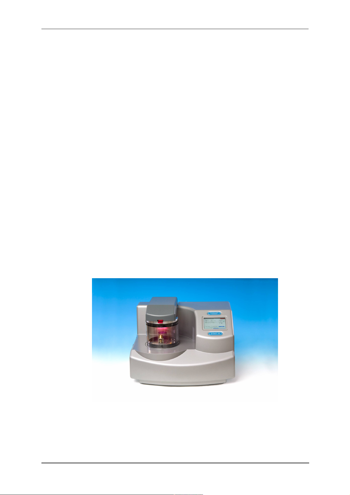
The Q150T system is a versatile sputter coater/turbo evaporator (see Figure 1-1) for
preparing specimens for examination by electron microscopy.
With a comprehensive selection of easily interchanged inserts and sample stages, the
Q150T can be used to:
Sputter coat samples using targets such as Chromium or Gold.
Evaporate support films and replicas for TEM and X-Ray analysis and conducting
coatings for SEM using 3mm or 6mm carbon rods or cords.
Evaporate metals upwards or downwards from a wire basket or molybdenum boat
arrangement.
Clean aperture strips.
There are three models in the Q150T range:
Q150T S Sputter coater version only.
Q150T E Carbon/metal evaporation version only.
Q150T ES Combined system with interchangeable inserts for sputter coating or
carbon/metal evaporation.
The instrument is fully adaptable to a wide range of specimens and offers easy loading
and unloading of samples. The changeover between sputtering and evaporation inserts
is simple. The system is fully automated with a user defined profile controlling the
pumping sequence, preheating, outgassing, the time and number of evaporation/sputter
bursts, and the current used during the process.
The Q150T can be fitted with a film thickness monitor (FTM), which measures the
coating thickness on a crystal in the chamber, to control the coating applied to the
sample. For example, the Q150T can automatically terminate a coating cycle when the
required thickness has been achieved.
Figure 1-1. Front view of the Q150T
The Q150T features a turbo molecular pump backed by a rotary vacuum pump and
controlled by the instrument throughout the fully automatic coating cycle.
The system is fitted with a vacuum shutdown system allowing the instrument to be
pumped down and switched off, with the chamber left under vacuum.
10473 - Issue 5 8 Q150T - Instruction Manual

1.2 Sputter Coating
Sputter Coaters are used in Scanning Electron Microscopy to provide an electrically
conductive thin film representative of the surface topography of the specimen to be
viewed, such films inhibit 'charging', reduce thermal damage, and enhance secondary
electron emission.
The Q150T S and Q150T ES employ a magnetron sputter target assembly. This
enhances the efficiency of the process using low voltages and giving a fine-grain (order
of 0.5nm Cr grain size), cool sputtering. The unit features a rotating sample table
ensuring even depositions (typically 5nm). It uses standard targets, avoiding the
necessity of special large profile targets. The instrument is fitted with a 57mm diameter
quick-change target (the sample chamber is 165mm in diameter) giving optimum
consumable cost performance. Alternative target materials are available.
A shutter assembly is fitted as standard, which allows sputter cleaning of oxidising
targets.
1.3 Carbon Coating
Carbon films, because of their mechanical stability, good electrical conductivity, and low
background signal are commonly used to prepare samples for Electron Microscopy
(EM).
Thin films of about 5 nm (50A) are used for particle support and as an isolating layer in
autoradiography. Thicker films are used in Scanning Electron Microscopy (SEM) also for
support, in addition to coating for X-Ray Microanalysis. In general, there is a need for all
these films to be fine grain, even coating, with uniform and reproducible film thickness.
The most common form of deposition is from resistance heated carbon rods. The rods
are shaped to achieve high current density with sufficient temperature to cause
evaporation. Carbon filaments can also be used, which at high temperature burn quickly,
from which has evolved the terminology: Carbon 'Flash' Evaporation. The resulting short
coating times and reduced total power input distinguishes it from the somewhat longer
process of carbon rod evaporation.
Q150T E and ES models feature a multi-change head system for Carbon rod, Carbon
fibre and metal evaporation.
Q150T Sample Preparation System
1.4 Metal Evaporation
By vaporizing a metal film onto a sample, it is possible to enhance the topographic detail
for high resolution analyses by TEM or SEM. This technique is particularly useful in the
analysis of biological specimens. The metal evaporant, usually a wire of, for example,
platinum or gold, is heated and vaporised by a filament (typically made of tungsten).
For downwards evaporation, evaporants usually in the form of wire: e.g gold, platinum,
aluminium, etc are placed directly onto the filament. For upwards evaporation, the
evaporant is placed in a ‘boat’ (typically made of molybdenum or tungsten).
The Q150T E and ES can be configured for metal evaporation in an upwards or
downwards direction.
1.5 Aperture Cleaning
In its metal evaporation configuration, you can use a Q150T E or Q150T ES to clean
aperture strips and other electron microscope components. With the component placed
in a molybdenum boat, it can be heated to evaporate contaminants.
Q150T - Instruction Manual 9 10473 - Issue 5

Q150T Sample Preparation System
2 Installation
It is important that this equipment is installed by skilled personnel in accordance with
these instructions. Failure to do so may result in damage or injury. 'If in doubt - ASK'.
2.1 Pre-installation
Identify a suitable location for the unit:
Mount the unit on a bench or the recommended trolley. The total weight of the system
is 33.4 kg.
The environment should have an ambient temperature range of 15ºC to 25ºC in a
non-condensing relative humidity of not more than 75%.
Sufficient ventilation is required, and positioning should be out of direct sunlight.
The system is rated for continuous operation.
2.1.1 Required Services
Argon
Supply for sputtering should be N4.8 (Zero Grade) 99.998% purity capable of supplying
3 litres/min at 4 psi. The regulator should be set at 4 psi.
The system is supplied with 3m plastic tubing 3mm I.D. x 6mm O.D. from a quick
release connector on the rear of the unit. It is the customer’s responsibility to connect
this tube to the pressure regulator from the gas bottle or plant supply. Typically a system
will use approx. 0.2 litres of Argon for a 4 minute sputter cycle (plus up to 4 litres if argon
is also used for purging and venting).
If bottle supply is adjacent it can be isolated locally, if not or plant supply,
local isolation valves should be fitted.
Nitrogen
Supply for purging should be N4.8 (Zero Grade) 99.998% purity capable of supplying 3
litres/min at 4 psi. The regulator should be set at 4 psi.
The system is supplied with 3m plastic tubing 3mm I.D. x 6mm O.D. from a quick
release connector on the rear of the unit. It is the customer’s responsibility to connect
this tube to the pressure regulator from the gas bottle or plant supply. Typically a system
will use up to 4 litres when Nitrogen is used for purging and venting.
If bottle supply is adjacent it can be isolated locally if not or plant supply,
local isolation valves should be fitted.
Pressure Regulators are Customer Supply, Nitrogen is recommended for
Purging for Economy, Argon must be provided for Sputtering, it can also be
used for Purging in the event of Nitrogen purge gas not readily available.
Typical regulators suitable for Argon and Nitrogen are the C106X/2 series available
from BOC
http://www.boconline.co.uk/en/products-and-supply/specialityequipment/regulators/two-stage-regulators/c106x2-series/c106x-2-series.html
Electrical supply
90-240V, 50/60Hz, 1350VA, including pump.
Vacuum Pump
Pump No 3 complete with Vac. Hose & Oil Mist Filter 35 litre/min 2m³/hr.
10473 - Issue 5 10 Q150T - Instruction Manual

2.2 Unpacking
1. Remove the Instrument from its packing and place it in its operational position.
2. Carry out a visual inspection to check for any signs of transit damage.
3. Remove the Accessories Pack, and check contents against Q150T Accessories
Pack shipping list.
4. Ensure that all areas of the Instrument are free of loose packaging material.
Check specifically the instrument chamber, glass cylinder, and gaskets. (Do not
use vacuum grease on gaskets).
5. If your unit includes a vacuum pump, carry out preliminary checks in accordance
with the manufacturer’s recommendations.
Q150T Sample Preparation System
CAUTION
Don’t try to lift the unit by yourself: it weighs 33.4kg. Get
someone to help you move it.
CAUTION
Do Not attempt to lift the lid from the chamber. Unlatch the grey
top cover and remove the 2 transit screws retaining the top plate
assembly. The set screw and the transit plate should be retained
with the instrument accessories in case further transit of the
instrument is necessary.
If you are intending to use an existing or alternative vacuum pump, and
have any difficulty with these connections, please contact our technical
support.
Q150T - Instruction Manual 11 10473 - Issue 5
2.3 Connections
Installation consists of the following steps:
Connect gas supplies (see below).
Make electrical connections (see page 13).
Connect the vacuum pump (see page 15).
Install the sample stage (see page 16).
If you want to install a different insert than that supplied with your instrument, please see
page 54. If you have ordered a Q150T ES, the instrument will be fitted with the sputter
insert, unless you have specifically requested another configuration.
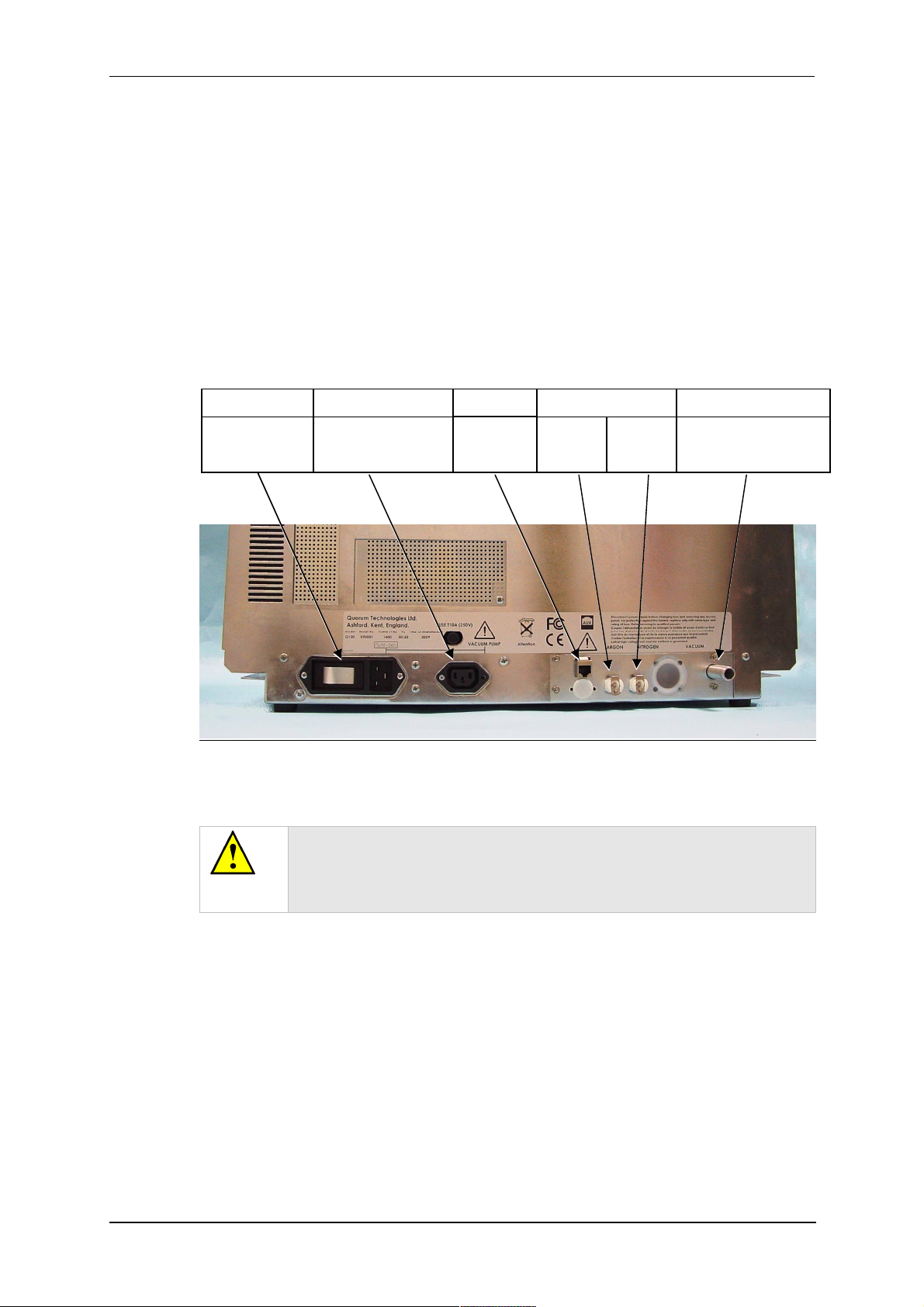
Figure 2-1 shows the location of connectors and switches on the rear panel of the
Q150T.
Power inlet with
integral On/Off
rocker switch
Q150T Sample Preparation System
Power supply for rotary
pump allowing control by
instrument.
Network
connection
GAS INLETSPUMP OUTLETPOWER INLET VACUUM CONNECTIONAUX
Argon
0.3bar
(4psi)
1
Nitrogen
0.3bar
(4psi)
2
Rotary Pump Vacuum
connection
Figure 2-1. Q150T Rear Panel
(1). S versions only
(2). If using air instead of Nitrogen, fit filter part no. 12842 see “Gas Connections”,
below.
WARNING
UNDER NO CIRCUMSTANCES SHOULD ANY OTHER
CONNECTIONS OR OUTLETS/INLETS BE USED FOR ANY OTHER
EQUIPMENT OR SERVICES.
10473 - Issue 5 12 Q150T - Instruction Manual
2.3.1 Gas Connections
1. Connect a suitable argon supply at a regulated input of 0.3bar (4psi) to the quick
connect Argon gas connector on the rear panel (see Figure 2-1. If you prefer, you
can use argon for both process and purge supplies.(recommended if coating with
oxidising targets). To do so, install a 'T' piece across both gas inlets.
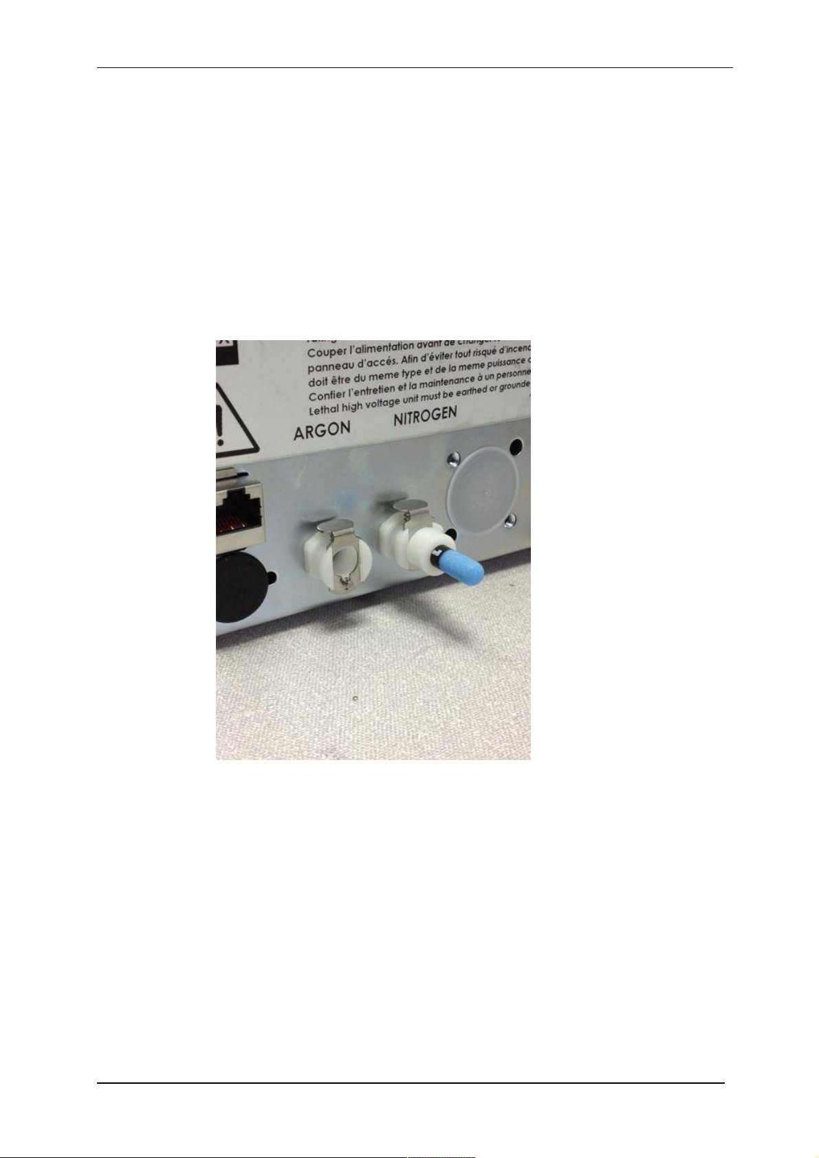
2. Connect a suitable nitrogen supply at a regulated input of 0.3bar (4psi) to the
quick connect Nitrogen connector on the rear panel. Air may be used in place of
nitrogen for venting (not recommended for oxidising targets) but it is important to
fit the filter (part no. 12842) to prevent ingress of dust (see Figure 2-2). Failure to
connect this filter could prevent the system venting at the end of a cycle.
Connectors are push-fit and will 'snap' into a locked position. To release a connector,
depress the metal tongue.
Q150T Sample Preparation System
Figure 2-2. Gas connectors with filter (part no. 12842) fitted to purge gas inlet
Q150T - Instruction Manual 13 10473 - Issue 5
Q150T Sample Preparation System
2.3.2 Electrical Connections
1. Connect the instrument to a suitable earthed single-phase ac supply using the
supplied cable. The lead should be fitted with the appropriate plug for your
country. Ensure the plug is firmly located.
WARNING – EARTH CONNECTION
This Equipment must be Earthed and fitted with the correct lead for the
country of operation. This Equipment is normally supplied from 3 pin
supply including Earth.
For fuse information, refer to Table 32.
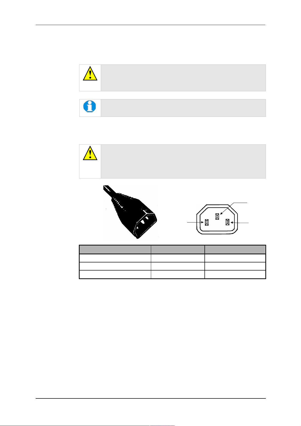
2. Connect the rotary pump power lead to the Pump Output connector on the rear
panel (see Figure 2-3). If the rotary pump has its own switch, ensure that this is
set to the ‘On’ position.
WARNING – PUMP OUTPUT
Check that the Power Output is suitable for the rotary pump. The Pump
Output is intended for connection to the pump supply only and provides
the electrical supply voltage at a maximum of 4 Amps.
PIN UK AND EUROPE U.S.A. AND CANADA
Pin 1 ( Live or Hot) Brown Black
Pin 2 ( Earth ) Green / Yellow Green
Pin 3 ( Neutral) Blue White
Figure 2-3. Power outlet lead wiring
2.3.3 Aux Network Connection
To link the Q150T to your network, use a standard CAT5/5e cable with RJ45 network
connectors to connect the AUX Network port directly to your computer’s network port or a
network hub/switch.
Pin 1
Live
Pin2
Earth
Pin 3
Neutral
10473 - Issue 5 14 Q150T - Instruction Manual

Q150T Sample Preparation System
2.3.4 Vacuum Connections
1. If you are using an existing or alternative vacuum pump, and have any difficulty
with connections, please ask for advice.
2. If the instrument is NOT going to be vented into an extraction system, fit an Oil
Mist Filter with metal adapter to the outlet of the vacuum pump. Please refer to
the manufacturer’s instructions.
3. Ensure that the vacuum pump is filled with the correct oil.
4. If the vacuum pump is fitted with an on/off switch, ensure that it is set to the 'on'
position to allow the instrument to control its power supply.
5. Connect the flexible vacuum hose to the spigot on the rear panel using the hose
clip provided. This is a push-on fit to the Instrument. Ensure that this is firmly in
place to the full length of the spigot.
A rotating vacuum spigot is available for more convenient hose
connection in installations where the instrument is to be located close
to a back wall (see page 69).
Q150T - Instruction Manual 15 10473 - Issue 5
Q150T Sample Preparation System
2.3.5 Fitting the Standard Stage
The Q150T is supplied with a standard stage (10067). For installation instructions for
other stages, see page 54. To install the standard stage:
1. Ensure that the instrument is vented and in standby mode.
2. Open the top cover fully so it rests against its backstop.
3. If there is already a stage in place, remove it by lifting carefully upwards.
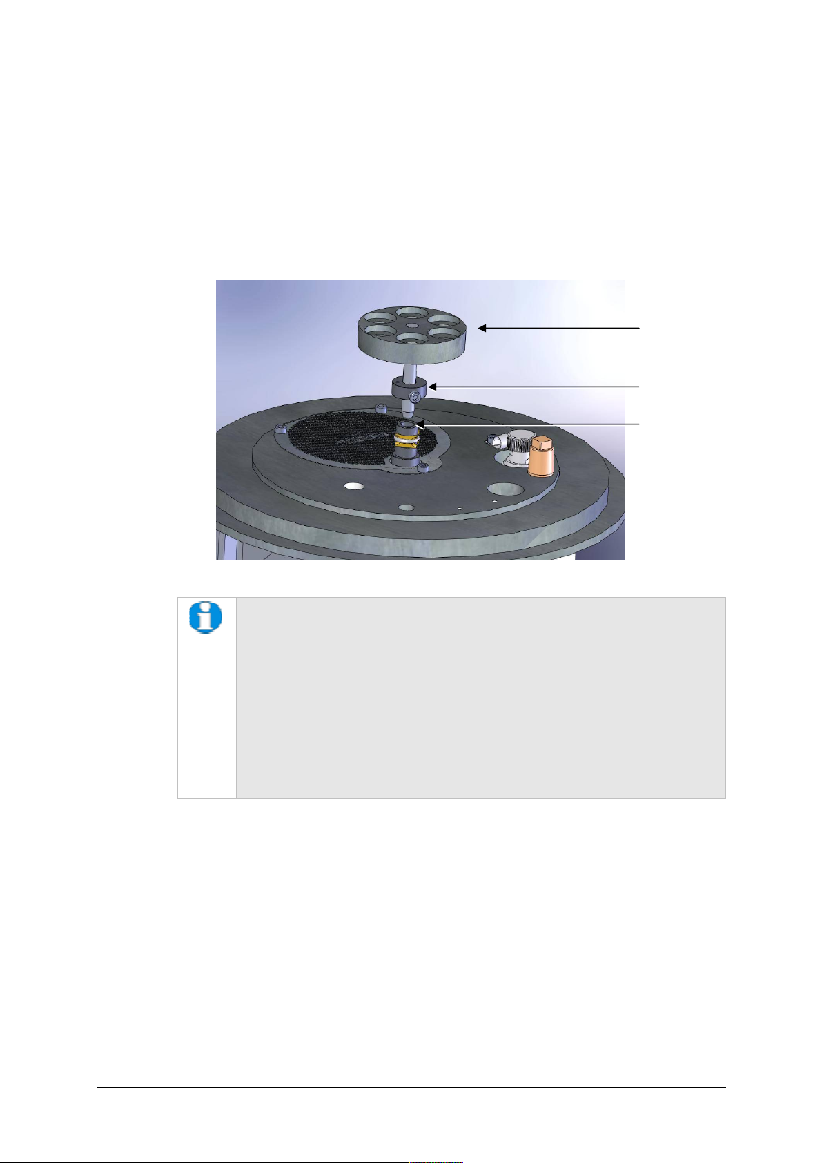
4. Fit the standard stage by locating its shaft into the top of the stage rotation drive
spigot protruding from the baseplate and with a twisting motion pushing it gently
down until the collar around the shaft rests on top of the drive spigot (see below).
Standard stage
Height-adjusting
collar
Rotation drive
spigot
Figure 2-4. Fitting the standard stage
You can adjust the height of the stage above the base plate by moving the
collar up or down the shaft. Unfasten the M3 screw with a hexagonal key,
slide the collar to the required position and retighten the M3 screw.
For maximum distance between the stage and the target, remove the collar
so that the underside of the stage rests on the top of the drive spigot. To
reduce the distance between the stage and target, fit the stage with the
alternative long shaft (10214 – supplied with stage).
When using small 1/8” pin stubs, it is advisable to unscrew the stage and fit it
upside down for easy access to the stub.
Note that the Q150T’s default tooling factors are based on a stage
height of 60mm from the base plate.
2.3.6 Optional Connections
For full connection details of optional units, where provided, please refer to separate
instructions. Any other connections on the rear panel not listed are for common
manufacturing and are not available for this instrument.
10473 - Issue 5 16 Q150T - Instruction Manual
Q150T Sample Preparation System
3 Operation
This chapter describes the basic operation of the Q150T. For more advanced use,
please see Working with Profiles on page 21 and Application Guidelines on page 28.
3.1 Switching On for the First Time
1. Ensure that you have completed the installation as described in the previous
sections.
2. Switch the instrument on using the rocker switch located on the rear panel. The
front panel LCD display should illuminate and show the initialising message.
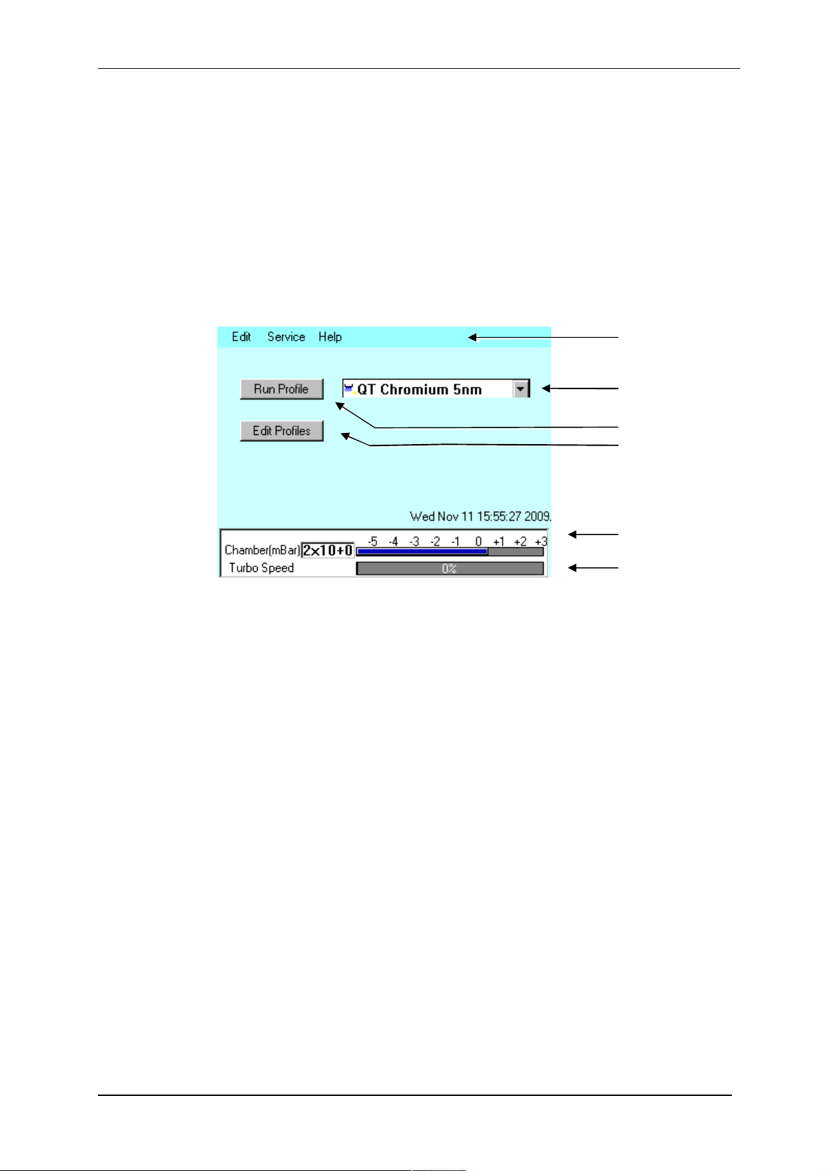
3. Once the instrument hardware and software has initialised, the standby screen is
displayed (see Figure 3-1).
Menu bar
Profile list box
Run Profile button
Edit Profiles button
Figure 3-1. Standby screen
3.1.1 The Standby screen
The Standby screen has three main parts:
A menu bar with Edit, Service and Help categories (see page 42).
Run Profile and Edit Profile buttons and a profile selector. Operate the instrument
simply by selecting a profile and tapping on the Run Profile button.
Pumping/vacuum information display: Chamber pressure reading and meter, and a
turbo speed indicator.
Chamber pressure
reading and meter
Turbo pump speed
meter
Q150T - Instruction Manual 17 10473 - Issue 5
Q150T Sample Preparation System
3.2 Running a Profile
Before you can run a profile, ensure you have:
Completed the installation as described on page 10.
Switched on the instrument (see section 17).
Loaded a sputter/coating target or loaded an evaporation source (see page 54).
To run a profile:
1. Load your sample onto the center of the sample stage.
2. Close the top cover assembly and press it firmly down to secure the latch.
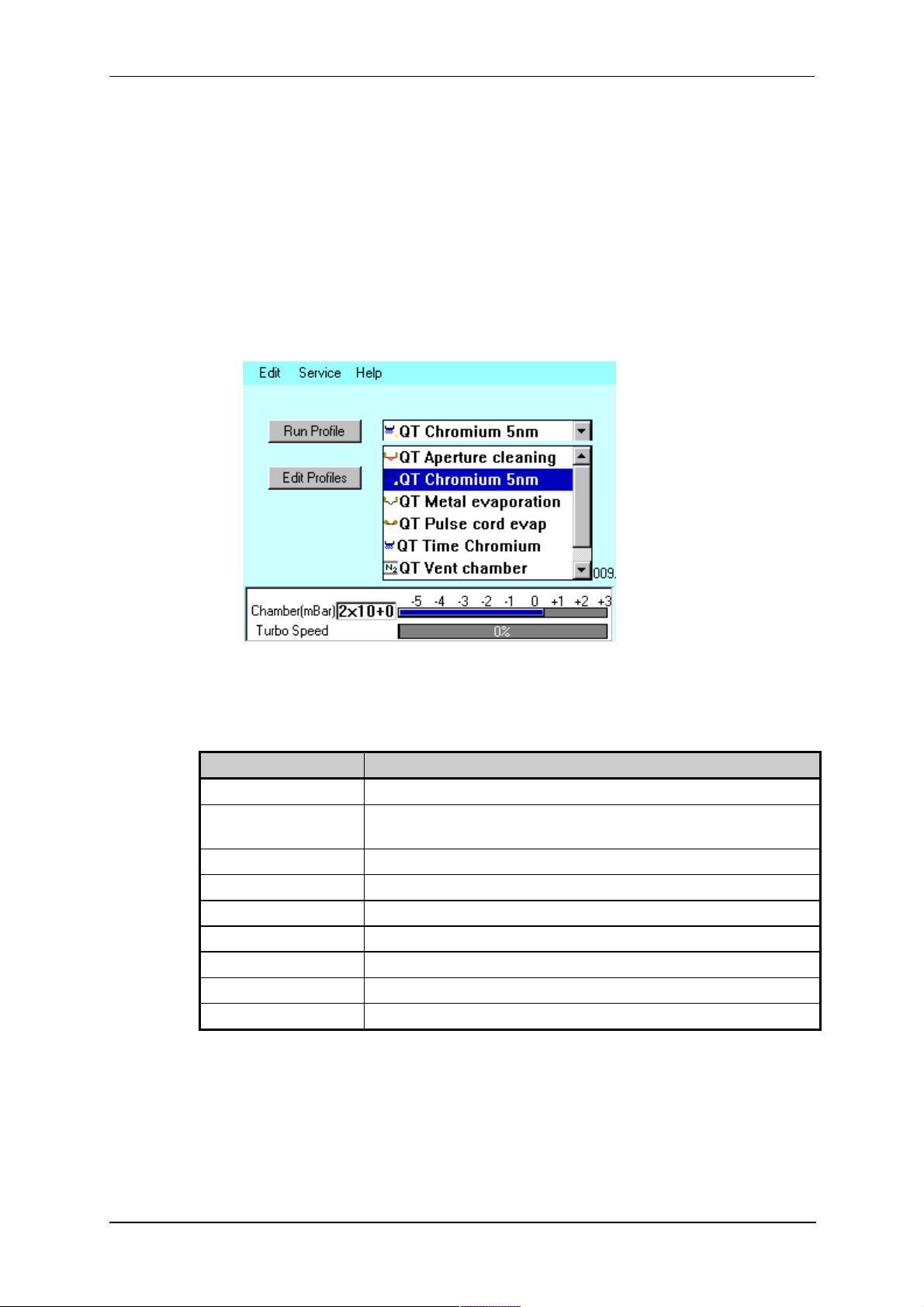
3. Tap on the down arrow button to open the dropdown list of profiles (see Figure
3-2).
Figure 3-2. Selecting a profile
4. The Q150T has several default profiles for common tasks as shown in Table 1.
Tap on the name of the profile you want to run.
Table 1 Q150T Default Profiles
PROFILE NAME PURPOSE
QT Time Chromium Sputter coating run using Chromium target (see page 28)
QT Chromium 5nm*
QT Metal evaporation Coating using metal evaporator (see page 31)
QT Aperture cleaning Default profile for aperture cleaning (see page 40)
QT Pulse rod evap Evaporation using carbon rods (see page 32)
QT Pulse cord evap Evaporation using carbon cord (see page 32)
QT Controlled pulse Evaporation using FTM termination of carbon cord (see page 32)
QT Vent chamber Vent sample chamber
QT Vacuum shutdown Pumps chamber to 1mBar to allow shutdown under vacuum
* Profile only present on systems equipped with FTM.
Sputter coating run using Chromium target terminated by FTM at a
coating thickness of 5nm (see page 28)
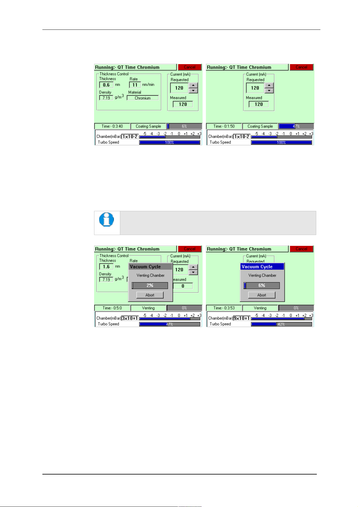
5. Tap on the Run Profile button. The Q150T starts pumping the sample chamber.
The progress of the run is shown through a series of on-screen messages (Figure
3-3).
10473 - Issue 5 18 Q150T - Instruction Manual
Q150T Sample Preparation System
Figure 3-3. A run in progress: with FTM installed (left) and without FTM (right).
6. If you want to stop a run while it is in progress, tap on the Cancel button.
7. At the completion of the run, the Q150T begins to vent the chamber (see Figure
3-4). If you want to record thickness control or current information, make a note of
it now. When the chamber has been vented, the display reverts to the standby
screen (see Figure 3-1).
Future versions of the Q150T software will allow logging of thickness
control and profile parameters through the instrument’s network
communication capabilities.
Figure 3-4. Venting the chamber: with FTM installed (left) and without FTM
(right).
8. When the chamber has been completely vented, the display reverts to the standby
screen. You can now remove your sample and set up another run.
Q150T - Instruction Manual 19 10473 - Issue 5
3.3 System Settings
The operation of the Q150T is controlled by its profile parameters. However, there are
several system parameters, which can be changed without altering the profile. A systemset parameter overrides the corresponding setting specified in the active profile. You can
make the new setting apply just to runs using the active profile or to all runs, irrespective
of the choice of profile.
To change a system parameter:
1. Open Profile Editor: from the standby screen, tap on the Edit Profile button or
choose Edit | Profiles from the menu bar.
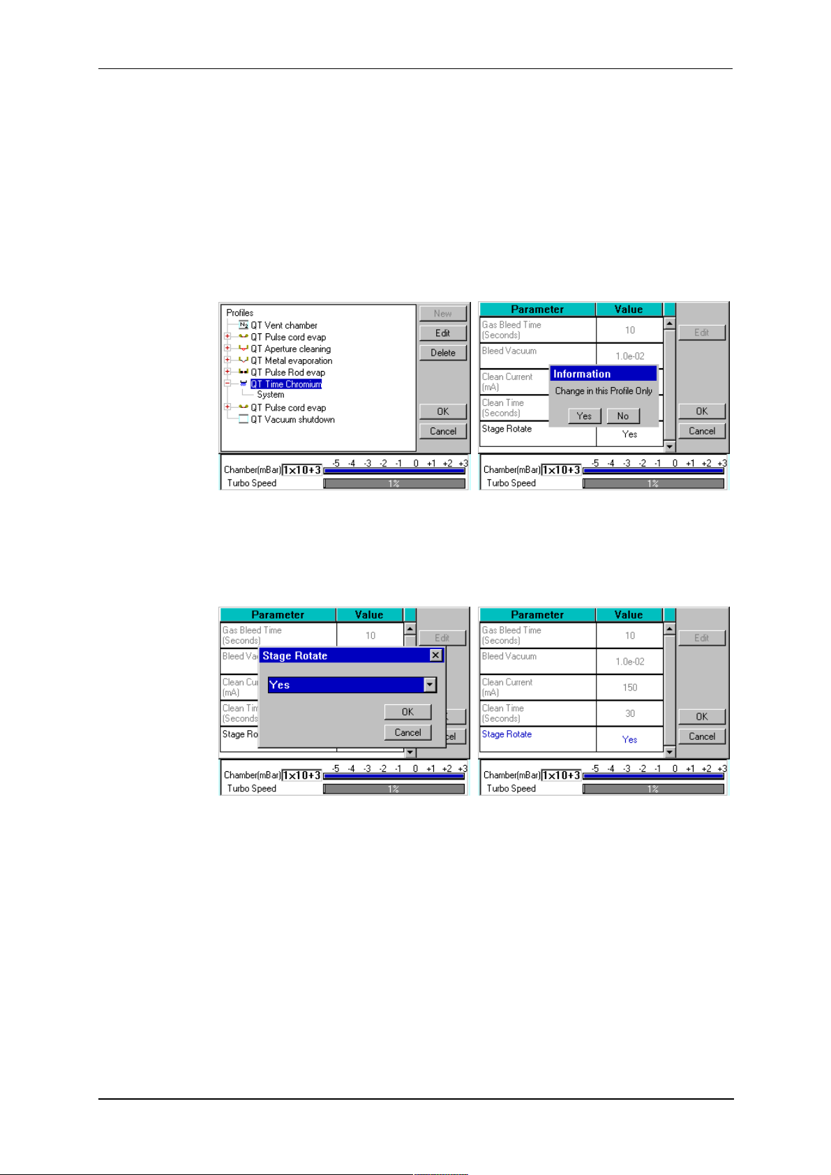
2. Tap on the + sign to the left of the currently active profile (see Figure 3-5 - left).
Q150T Sample Preparation System
Figure 3-5. Listing system properties for a profile
3. Tap on System. System Property Editor is displayed (see Figure 3-5 - right).
4. You are prompted to confirm whether the changes are to be applied to runs using
this profile only or to all runs. Tap on the Yes button to apply changes to the active
profile only, or No to apply the change to all runs.
Figure 3-6. Changing the Stage Rotate system property
5. Tap on the value of the system property you want to change (in this case, Stage
Rotate). Amend the setting as required and confirm the change by tapping on the
OK button. Tap on the Cancel button to cancel any change (see Figure 3-6).
6. Altered system parameters are shown with blue text.
7. Tap on the OK button to exit the System Property Editor.
10473 - Issue 5 20 Q150T - Instruction Manual
Q150T Sample Preparation System
4 Working with Profiles
The operation of the Q150T is controlled by a profile. This describes the sequence of
operations in sputter coating or evaporation cycles. You can also create profiles to carry
out simple operations such as pumping or venting the sample chamber. Many of the
basic operations such as pumping, outgassing or venting the chamber occur
automatically as does the sequence in which they occur.
The Q150T is supplied with several default profiles to perform the basic and most
common operations (see Table 1). To make your own profiles, customised for your
specific applications, you can:
Edit an existing default profile
Create a new profile
4.1 Editing the Active Profile
To edit the profile currently selected on the standby screen, tap on the Edit Profile
button. The editable parameters of the selected profile are displayed (see Figure 4-4).
Now refer to the Editing Profile Parameters section on page 24.
4.2 Profile Editor
To create, edit or delete any profile:
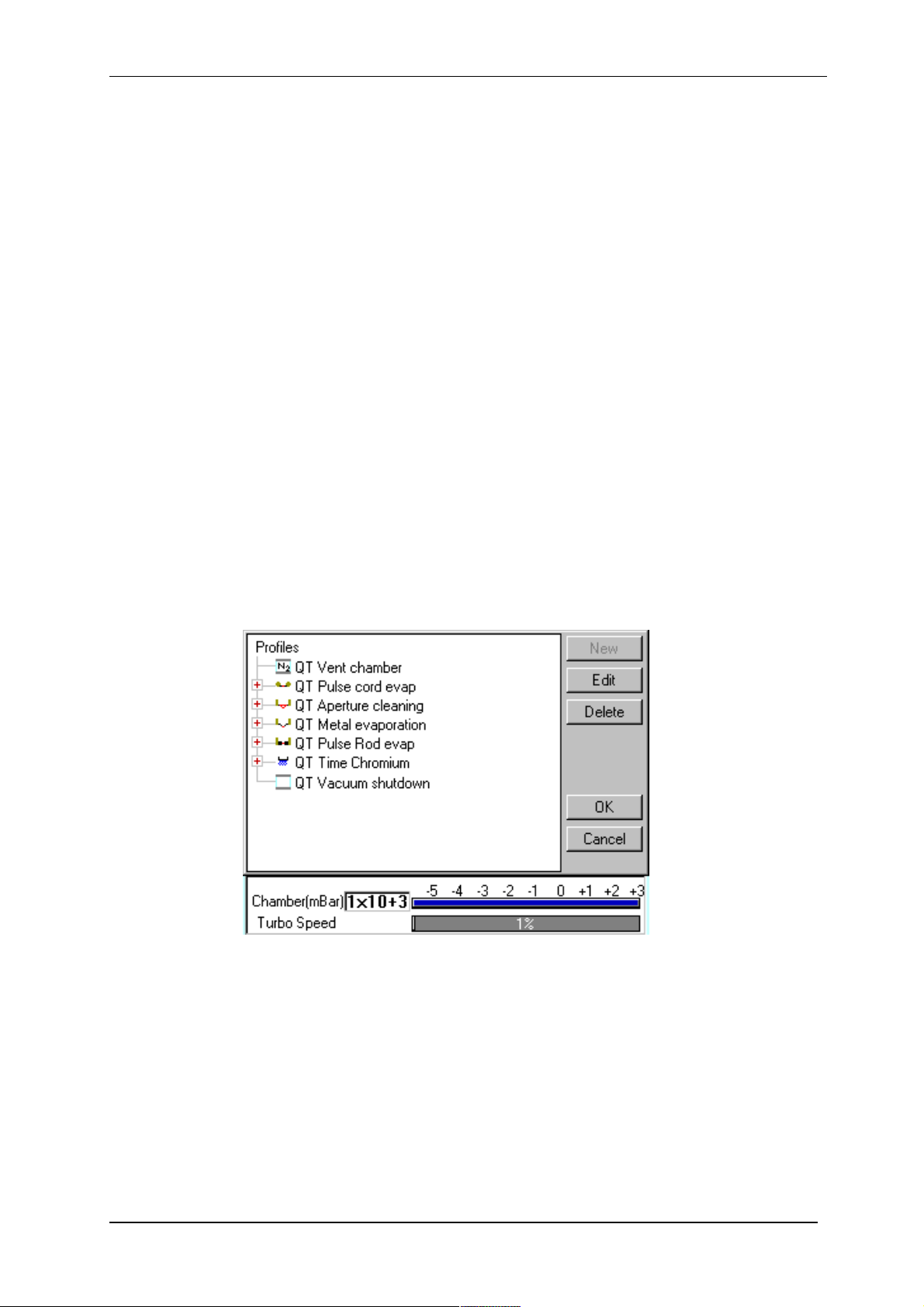
1. Select Edit | Profiles from the menu bar. Profile Editor is displayed (see Figure
4-1).
Figure 4-1. Profile Editor
Q150T - Instruction Manual 21 10473 - Issue 5
Q150T Sample Preparation System
In its main window, Profile Editor lists all existing profiles. To the left of each
profile name, an icon denotes the type of profile (see Table 2).
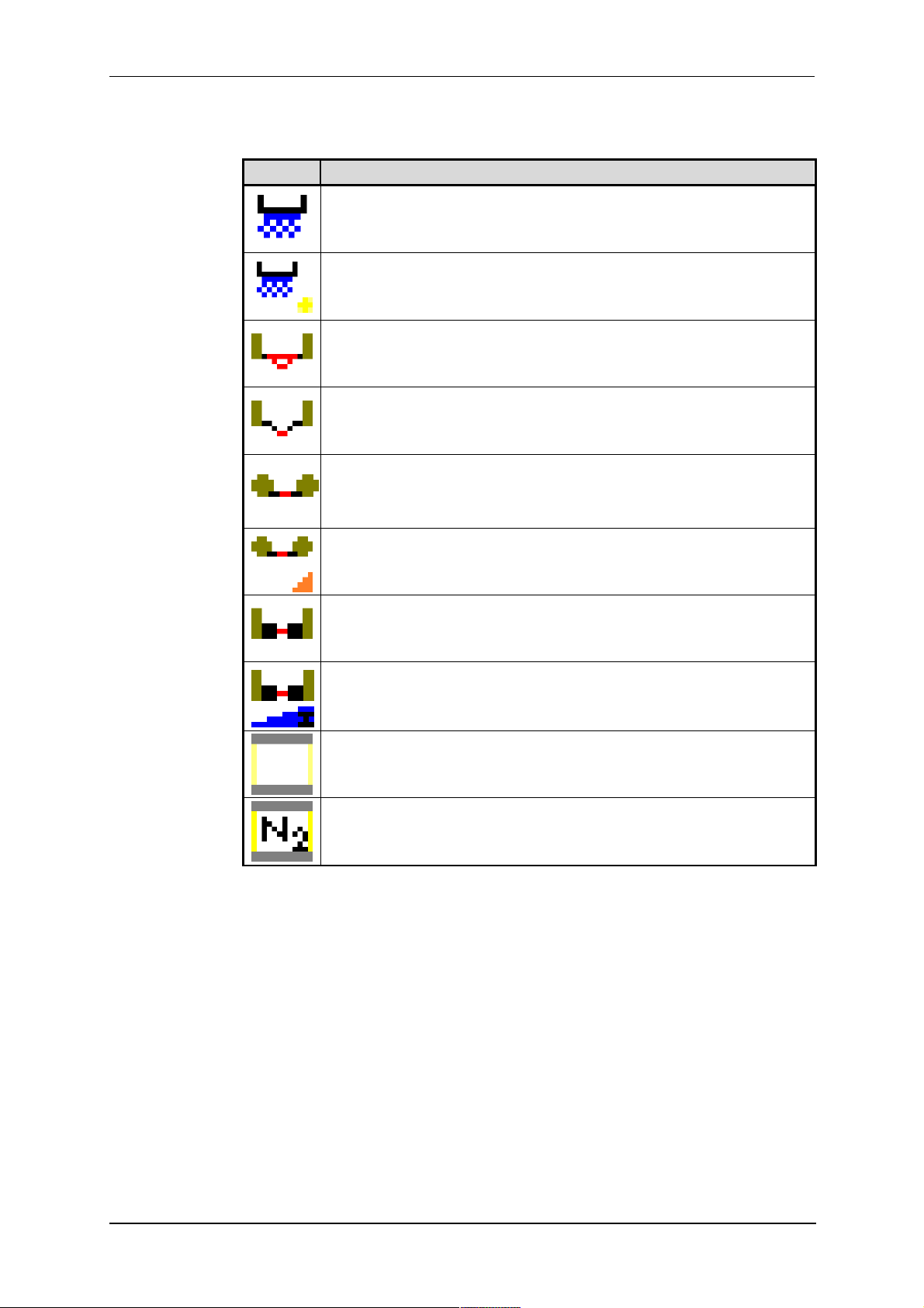
Table 2 Profile icons
Icon Profile/Process Type
Timed sputter (see Table 24)
FTM terminated sputter (see Table 24)
Aperture cleaning (see Table 29)
Metal evaporation (see Table 28)
Pulse cord evaporation (see Table 25)
QT Controlled pulse cord (see Table 26)
Pulse rod evaporation (see Table 25)
Ramped carbon
Vacuum shutdown (see Table 30)
Vent chamber
2. Tap on one of the buttons on the right side of the editor:
a. To create a new profile, tap on the New button (see Creating a new
profile).
b. To edit a profile, tap on its name and then tap on the Edit button. The
Profile’s parameters are displayed (now see Editing Profile
Parameters)
c. To delete a profile, tap on its name and then tap on the Delete button.
10473 - Issue 5 22 Q150T - Instruction Manual
Q150T Sample Preparation System
4.2.1 Creating a New Profile
To create a new profile:
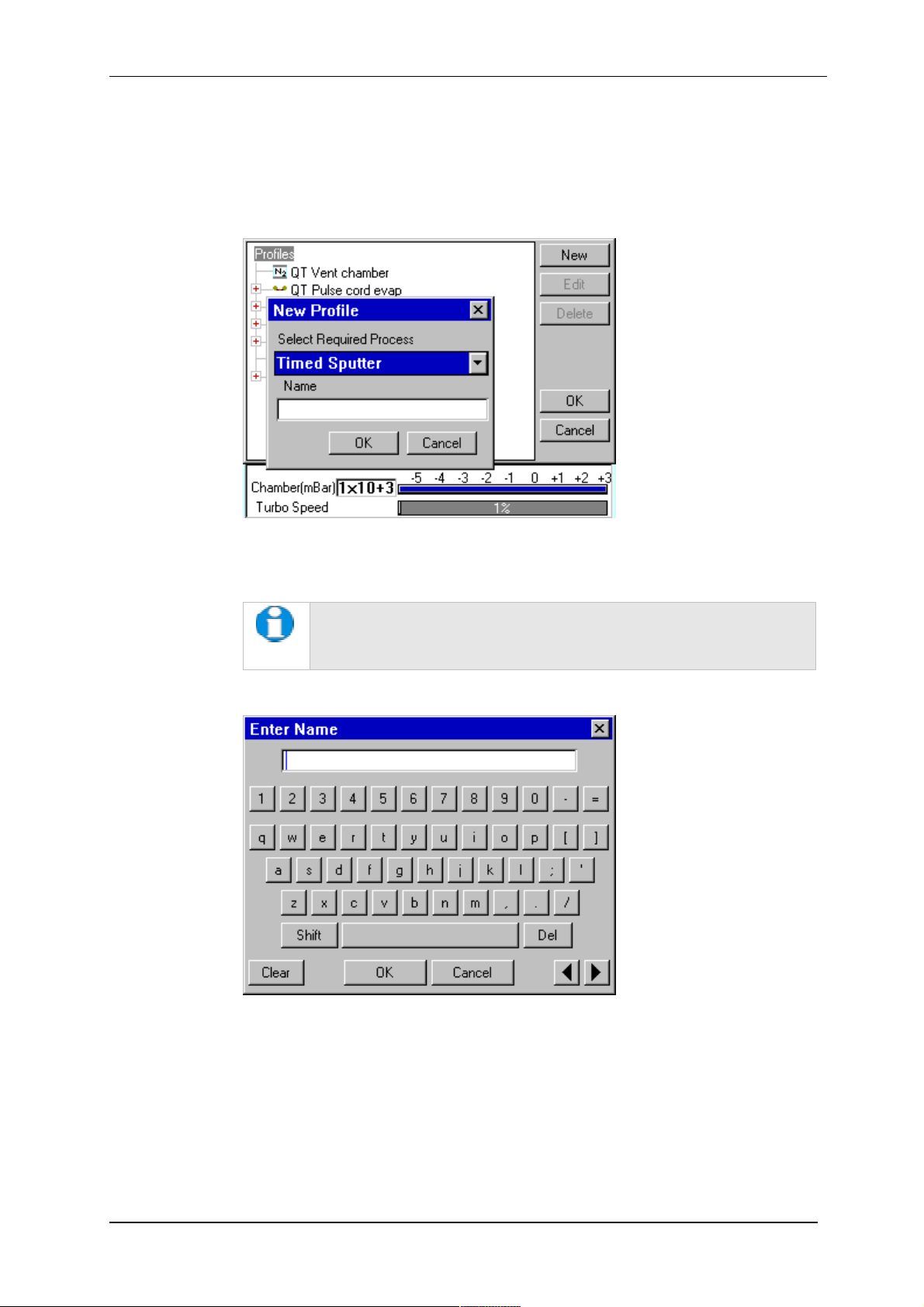
1. With Profile Editor displayed, tap on Profiles at the root of the profile ‘tree’.
2. Tap on the New button.
3. The New Profile dialog box is displayed (see Figure 4-2).
Figure 4-2. Creating a new profile
4. Choose the type of profile you want from the Select Required Process drop-down
list).
See Table 2 for a list of all the available processes. Note that the
processes listed are different for Q150T E, Q150T S and Q150T ES
models.
5. Enter a name for the profile: tap in the Name field to display the on-screen
keyboard (Figure 4-3) in the Enter Name dialog box.
Figure 4-3. Entering a new profile name
6. Tap on the OK button to confirm the changes to the profile. Alternatively, tap on
the Cancel button to close the dialog box without creating a new profile.
7. The new profile is created using the default settings for the chosen process type.
8. Now refer to the Editing Profile Parameters section, below.
Q150T - Instruction Manual 23 10473 - Issue 5
Q150T Sample Preparation System
4.2.2 Editing Profile Parameters
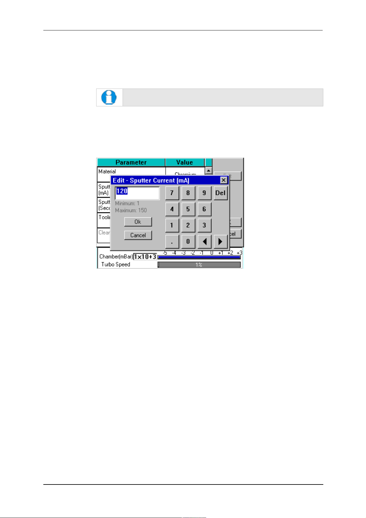
1. To edit a profile, tap on its name in Profile Editor and then tap on the Edit button.
A table showing the profile’s parameters is displayed.
2. To edit a parameter, tap on its value (it is then highlighted in blue) and then tap on
the Edit button.
If a parameter is shown in grey text, you do not have the necessary
user privileges to edit it. See page 49 for details.
3. Change the value as required (see Figure 4-4). The instrument displays a dialog
box for editing purposes, with either a numeric keypad or keyboard as required.
The dialog box also shows the allowed values for the parameter.
4. Click on the OK button to confirm the change or on the Cancel button to restore
the previous value.
Figure 4-4. Editing Profile Parameters
5. Edit other parameters as required.
6. On the Profile window, click on the OK button to confirm the changes to the profile
or on the Cancel button to restore the previous values.
To see a list of the parameters used in profiles see page 78.
10473 - Issue 5 24 Q150T - Instruction Manual
4.3 Materials
The software contains a database of the most common elements and alloys used in
sputtering and evaporation applications (see Table 3). The choice of material is the first
parameter in a Sputter Coating profile. The embedded density information is used to
calculate film thickness.
Material
Aluminium 2.70
Carbon 2.25
Titanium 4.54
Chromium 7.19
Nickel 8.90
Copper 8.96
Silver 10.50
Palladium 12.02
Gold / Palladium (Au/Pd) (80:20 mix) 17.86
Tungsten 19.30
Gold 19.32
Platinum / Palladium (Pt/Pd) (80:20 mix) 19.56
Platinum 21.45
Iridium 22.40
User Defined allowable range 1.00 - 23.00
Q150T Sample Preparation System
Table 3 Materials and their density
Density
3
g/cm
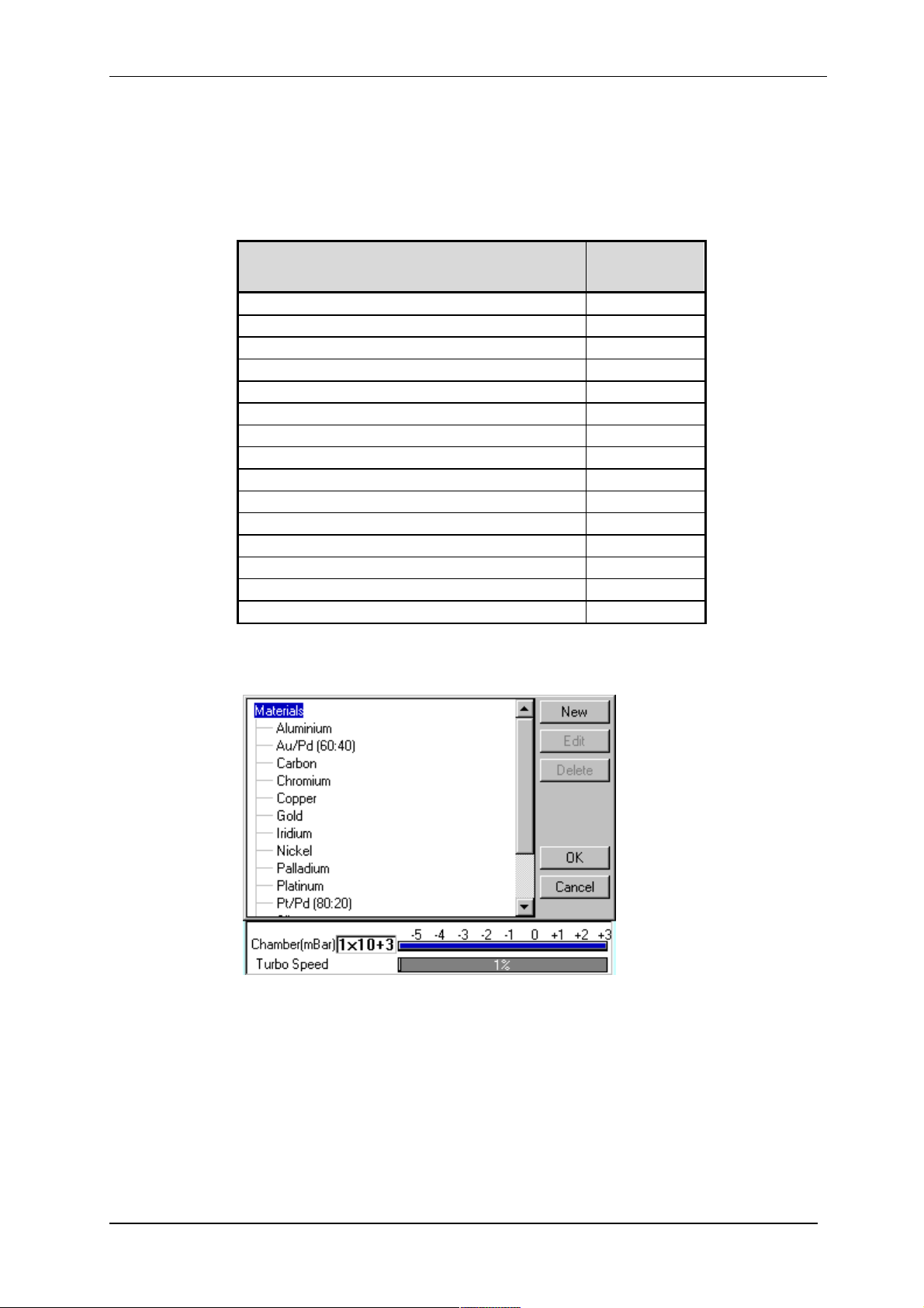
To create, edit or delete a new entry in the material database, select Edit | Materials
from the menu bar. Materials Editor is displayed (see Figure 4-5).
Figure 4-5. Materials Editor
Materials Editor lists all the existing materials in the Q150T database and allows you to
add new materials or edit existing material definitions.
Q150T - Instruction Manual 25 10473 - Issue 5
Q150T Sample Preparation System
4.3.1 Creating a New Material
To create a new material:
1. Select Edit | Materials from the menu bar. Material Editor is displayed (see
Figure 4-5).
2. Tap on Materials at the root of the material ‘tree’.
3. Tap on the New button. The New Material dialog box is displayed.
4. Enter a name for the profile: tap in the Name field to display the on-screen
keyboard (Figure 4-6) in the Enter Name dialog box.
5. Tap on the OK button to confirm the changes to the material. Alternatively, tap on
the Cancel button to close the dialog box without creating a new material.
6. The new material is created using the default settings for the chosen process type.
7. Now refer to the Editing Material Parameters section.
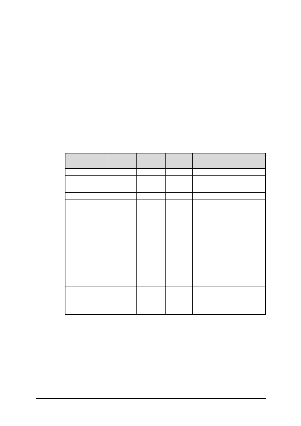
4.3.2 Editing Material Parameters
Each material is defined by the parameters shown in Table 4:
Table 4 Material parameters
Name Default
Value
Density 10 1 30
Material Type oxidising noble oxidising
Minimum
Value
Maximum
Value
Comment
Sputter Current 50 1 150
Clean Current 150 100 150
Material Tool 0.1 10
Sputter cleaning
mode*
Sputter stop
cleaning at (Volts)*
* Displayed for information only. Changes if required will need to be carried out by a Quorum
agent.
Timed Specifies how the material will be
cleaned. Options are:
Timed
Continuous sputter for fix time.
Pulse above
Cycle plasma until target voltage
is above that specified in
Sputter stop cleaning at
Pulse below
Cycle plasma until target voltage
is below that specified in
Sputter stop cleaning at
Only used during pulse cleaning
of target.
250 90 600 Target voltage that needs to be
achieved before cleaning is
completed and the coating starts.
Only used during pulse cleaning
of target.
10473 - Issue 5 26 Q150T - Instruction Manual
Q150T Sample Preparation System
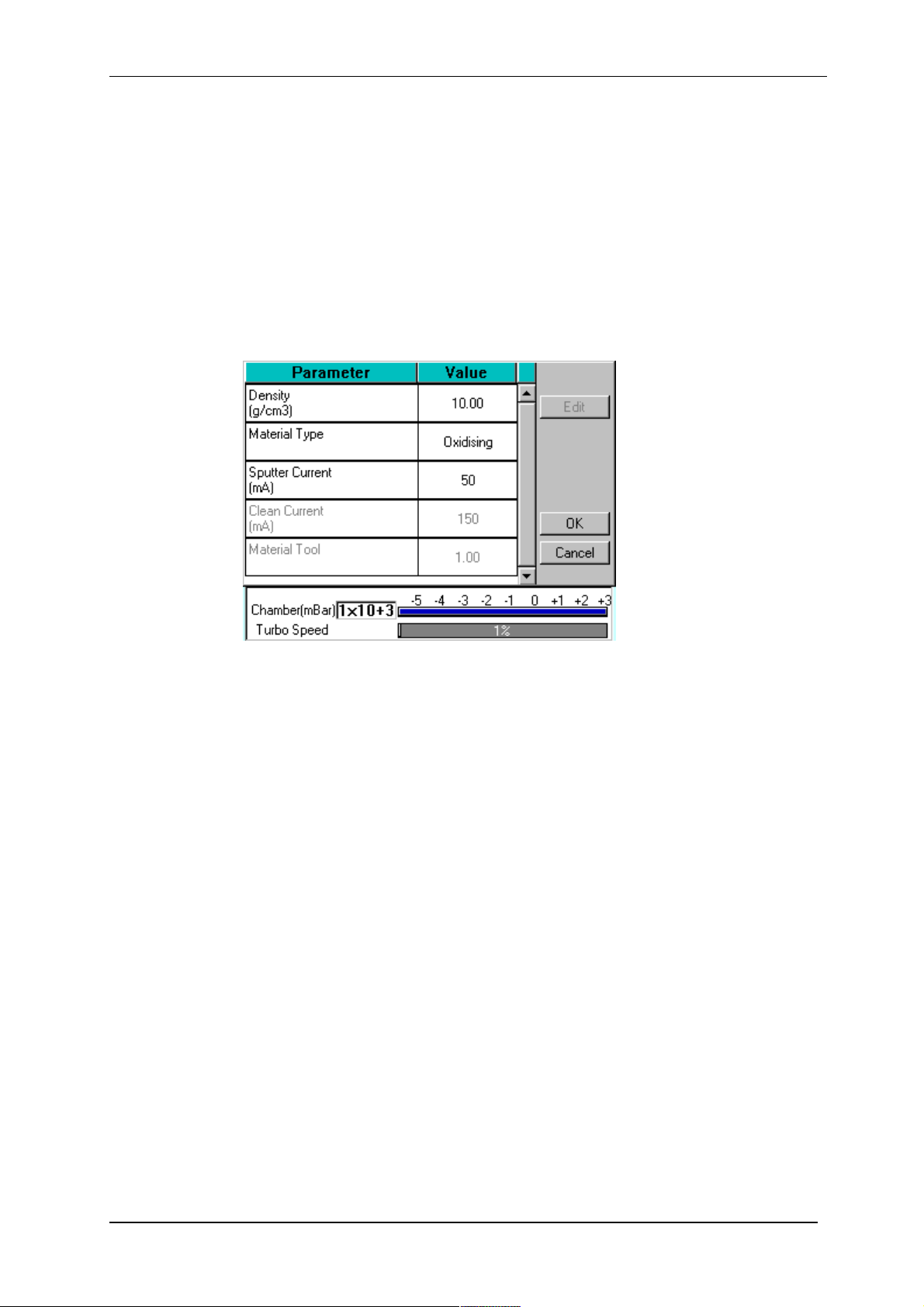
To edit a material:
1. Tap on the material’s name and then tap on the Edit button.
2. To edit a parameter, tap on its value (it is then highlighted in blue) and then tap on
the Edit button.
3. Change the value as required. The instrument displays a dialog box for editing
purposes, with either a numeric keypad or keyboard as required. The dialog box
also shows the allowed values for the parameter.
4. When you edit a value, tap on the OK button to confirm the change or on the
Cancel button to restore the previous value.
5. Edit other parameters as required.
6. Back in the Material Editor, tap on the OK button to confirm the changes to the
material or on the Cancel button to restore the previous values.
Figure 4-6. Material Parameters
4.3.3 Deleting a Material
To delete a material, tap on its name and then tap on the Delete button.
Q150T - Instruction Manual 27 10473 - Issue 5

Q150T Sample Preparation System
5 Application Guidelines
This section describes the QT processes and their typical applications.
5.1 QT Timed Sputter
Suitable for the following applications:
SEM coatings for tungsten emission SEM.
High resolution SEM coatings for field emission SEM.
General thin film coatings.
Target materials: Au, Au/Pd or Pt
5.1.1 Tungsten SEM work
For this type of work, the aim is to achieve a typical thickness of 10-20nm from a gold
target. Figure 9-1 shows the deposition graph for gold. With a current of 20mA, a
deposition rate of 20nm/minute is typically achieved (assuming that the sample height is
set to the default height of 60mm and the vacuum is 1x10⁻²mBar).
To achieve a gold coating of 10nm create a new profile based on QT Timed Sputter: The
default Material setting is Au.
Edit the current to 25 mA.
Set the time to 30 seconds.
If necessary adjust the time or current slightly to modify the thickness.
5.1.2 High resolution SEM coatings for field emission SEM
Generally, the recommended target materials are Cr or Ir and the objective is to
generate a coating thickness of 5-10 nm.
The deposition graph using a Cr target is shown in Figure 9-2. With a current of 100mA,
a deposition rate of 20nm/minute is typically achieved (assuming that the sample height
is set to the default height of 60mm and the vacuum is 1x10⁻²mBar)
To achieve a Cr coating of 10nm, create a new profile based on QT Timed Sputter:
Set the material to Cr.
Edit the current to 100 mA.
Set the time to 30 seconds.
If necessary adjust the time or current slightly to modify the thickness.
10473 - Issue 5 28 Q150T - Instruction Manual

Q150T Sample Preparation System
5.1.3 Aluminium thin film
Aluminium is often difficult to coat due to its fast oxidizing properties. Also, its oxidized
layer is difficult to remove as it reduces the required target voltage to produce a sputter
current of 150mA. This increases the time required to clean the target.
However, the Q150T is set up to cycle the plasma which reduces this cleaning time. The
cleaning cycle is terminated when the target voltage rises above 300V, thus preventing
an already clean target coating the chamber excessively.
As an example, to achieve an Aluminium coating of 100nm:
1. Create a new profile based on QT FTM Terminated Sputter.
2. Edit the newly created profile.
3. Set the material to Aluminium.
4. When prompted, select Use material defaults. This applies a sputter current of
150mA to clean the target.
5. Edit the Terminate thickness setting to 100nm.
6. Tap on the OK button to close the Editor.
The clean time in the System properties should be between 10 and 30 seconds.
However, leave at the default value of 30 seconds for this setup. The Q150T applies the
optimum parameters for the cleaning cycle appropriate to your selection in the material
list (in this case, aluminium).
On running the above process the coater will:
1. Pump down to the clean stage as before.
2. Clean the target for the time specified by clean time in the profile.
3. Wait for 20 seconds with the plasma off.
4. Repeat the procedure until the target voltage is above 300V at the end of the
clean cycle for two consecutive cycles.
5. Continue with the standard sputter cycle.
If the target voltage fails to reach 300V after 15 cycles (see note below) the process is
stopped automatically. This might occur if the target has not been used recently. Vent
the system, remove the target and clean it manually using a fine abrasive. Repeat the
process.
The maximum of 15 cycles is determined by the Max pulse clean cycles
property in Generic Sputter parameters (see page 45). Note
administrator level access is required to change this property.
Q150T - Instruction Manual 29 10473 - Issue 5

Q150T Sample Preparation System
5.2 QT FTM Terminated Sputter
This process (only available if the FTM is fitted) is suited to the following typical
applications:
SEM coatings for tungsten emission SEM.
High resolution SEM coatings for field emission FE- SEM.
General thin film coatings.
5.2.1 High resolution SEM coatings for field emission SEM
For High resolution SEM coatings for field emission SEM, assuming the chosen target
material for this application is Cr.
Generally, the recommended target materials are Cr or Ir and the objective is to
generate a coating thickness of 5-10nm.
To achieve a Cr coating of 5nm, create a new profile based on QT FTM Terminated
Sputter:
Set the material to Cr.
When prompted, select use material defaults. This applies a sputter current of 120mA
and automatically sets the clean target current to 150mA and the terminate thickness
to 5 nm.
If necessary adjust the thickness if the coating is not sufficient.
5.2.2 General thin film coatings
As an example, to achieve a silver coating of 100nm:
Create a new profile based on QT FTM Terminated Sputter.
Edit the newly created profile.
Set the material to Silver.
When prompted, select use material defaults. This applies a sputter current of 50mA
and a terminate thickness to 5nm.
Edit the terminate thickness setting to 100nm.
10473 - Issue 5 30 Q150T - Instruction Manual

Q150T Sample Preparation System
5.3 Metal Evaporation
This process is designed for the following applications:
Alternative coatings methods for SEM samples where sputtering is not available.
Coating metal films on Non EM substrates.
It is only available with Q150T E/ES models equipped with the optional metal
evaporation insert. To achieve a specific coating depth, the FTM must be installed.
5.3.1 How to achieve a 20nm gold coating
Fit the tungsten filament to the evaporation insert as described on page 59.
Load the filament with a small quantity of the gold to be evaporated. Carefully fit the
insert as described on page 58.
1. Create a new profile based on Metal evaporation.
2. Edit the new profile:
Change the material from Carbon to Gold.
Change outgas time to a minimum of 2 seconds
Set the outgas current to 0 (out gassing is not necessary for this material).
3. Ensure the FTM cover is open
4. Run the new profile.
5. When the Pump Hold window is displayed, tap Continue when ready to proceed.
6. When the evaporate window is displayed use either the right arrows or the slider to
increase the requested current gradually until evaporation can be seen on the film
thickness monitor display. The measured current may differ from the requested
current at this point due to changes in impedance of the source while the metal is
melting.
Figure 5-1. QT Metal evaporation process
7. When the required thickness of 20nm is achieved, tap the Z button to the left hand
side and the current will immediately reduce to zero.
Q150T - Instruction Manual 31 10473 - Issue 5

Q150T Sample Preparation System
5.4 Pulsed Cord Evaporation
This process is designed for preparing conductive carbon coatings for SEM specimens
for X-ray microanalysis EDX and WDX. It is only available with Q150T E/ES models
equipped with the carbon cord insert option.
5.4.1 How to create a 20nm carbon coating
1. Install the carbon cord insert as described on page 58.
2. Ensure the stage is fitted with the shorter support shaft to give the maximum
source-to-stage distance.
3. Create a new profile based on QT Pulsed cord evaporation.
4. Edit the newly created profile setting the parameters as shown in Table 5.
5. Run the new profile.
Table 5 QT Pulsed cord evaporation parameters for 20nm coating.
Parameter Value
Pulse Current 50A
Pulses Length 3 seconds
Number of Pulses 1
Out Gas Time 60 seconds
Out Gas Current 30A
Pump Hold Yes
5.5 Controlled Pulse Cord Evaporation
This process is used for preparing conductive carbon coating using carbon cord.
During the process the coating is built up of multiple thin layers using short current
pulses (see Figure 5-2). This reduces the heating effect on the sample and allows the
FTM to be used to terminate the coating.
5.5.1 Using Controlled Pulse to create a 15nm coat or 2-3nm for EBSD
6. Install the carbon cord insert as described on page 58 ensuring that the C5421
carbon cord is used. Note the springs in the insert must be removed to ensure that
the cord does not fuse prematurely.
7. For the default tooling factor to be valid the stage should be fitted so the top of the
sample is 60mm above the base plate.
8. Create a new profile by pressing the new button in the profile viewer and selecting
Controlled pulse cord.
9. Edit the newly created profile setting the parameters as shown in Table 6. If an
EBSD coating is required, set the terminate thickness to the required thickness i.e.
3nm.
Table 6 QT Controlled Pulsed cord evaporation parameters for 25nm coating.
Parameter Value
Terminate thickness
Pulse Current 54A
Pulses Length 1 seconds
Pulse Interval 10 seconds
15 nm User selectable
The remaining properties have been optimised for coatings between 2 and 15nm
with the top of the sample 60mm from the base plate. Thicker coatings at this
stage position can be achieved. However this will increase the risk of the cord
fusing before reaching the required thickness. If the cord does fuse it tended to
deposit about 6nm, thus it can cause the required thickness to be exceeded. In
10473 - Issue 5 32 Q150T - Instruction Manual

Q150T Sample Preparation System
order to reduce this error the system attempts to detect when the cord is about to
fuse. If detected the coater will assume next pulse will produce 6 nm thus will
apply the pulse if the predicted outcome would be closer to the terminate value.
For a full list of profile parameters see Table 26.
10. Run the new profile.
The reliability of this process depends on the operation of the FTM. The
stability of the FTM is affected by the quality of the crystal. A crystal will need
to be changed before the end of its maximum life. This can even be before
the FTM status indicates 10% used (see page 51) as the deposited carbon
will increase the thermal errors and can easily flake. These effects will
increase if materials other than carbon are deposited on the crystal.
Figure 5-2. Typical 12nm Controlled pulse evaporation
Q150T - Instruction Manual 33 10473 - Issue 5

Q150T Sample Preparation System
5.6 Pulsed Rod Evaporation
Use this process for preparing TEM coatings for applying carbon reinforcement layers
onto formvar grids. It is only available with Q150T E/ES models.
5.6.1 How to create a conductive layer for SEM
1. Install the carbon insert as described on page 54. Ensure that the carbon rods are
prepared with a 1.2mm diameter spigot correctly as described on page 56.
2. Ensure the stage is fitted with a shorter support shaft to give the maximum sourceto-stage distance.
3. Create a new profile based on QT Pulsed rod evaporation.
4. Edit the newly created profile setting the parameters as shown in Table 7.
5. Run the new profile.
6. The thickness of coating can be varied by adjusting the stage height, raise the
stage to increase thickness, lower to reduce.
Table 7 QT Pulsed rod evaporation parameters for conductive layer for SEM
Parameter Value
Material Carbon
Pulse Current* 62A
Pulses Length 3 seconds
Number of Pulses 1
Out Gas Time 10 seconds
Out Gas Current 40A
CAUTION: For pulsed rod evaporation, the recommended pulse current
range is 60-65A. Currents above this may activate the power supply
safety trip causing the unit to shut down.
10473 - Issue 5 34 Q150T - Instruction Manual

Q150T Sample Preparation System
5.7 Ramped Profile
The Q150T Ramped Profile produces carbon coatings from a shaped carbon rod. We
recommend this profile instead of the pulse carbon rod process if you require a
consistently repeatable deposited thickness.
Generally, this process requires the use of the extended height chamber (see page 69).
The short chamber may be used for a coating thickness greater than 12nm although the
FTM will be inaccurate due to the close proximity of the high temperate rods.
5.7.1 Carbon insert setup
1. Use the rod shaper with the red handle (provided in the accessory pack) to
prepare two carbon rods each with a spigot 5mm long and with a diameter of
1.4mm diameter (see page 57).
2. You will then need to shape one of these rods to form a wedge using the wedge
tool (Part No. 12097). This tool can be used to shape 3mm or 6mm rods. Use the
end which has the grove closest to the plate to shape 3mm rods (see Figure 5-3,
detail B).
3. Hold the tool with the grove to be used uppermost.
Figure 5-3. Wedge tool (Part No. 12097)
4. Place the rod with its shaped end into the grove ensuring the rod is pushed up to
the shoulder.
5. File the rod so it is level with the metal tool. For best results, tap the dust out of
the grove several times during this shaping process being careful not to move the
rod.
6. Fit the flat-ended rod into the carbon gun (see page 56).
7. Fit the wedge-shaped rod with its point closest to the plate of the insert (see Figure
5-4). Ensure that the sliding clamp of the insert is pulled back approximately 5mm
and the point of the spigot is resting on the end of the plain spigot. It may be
necessary to swap the side of the wedged spigot or to rotate the plain spigot.
Figure 5-4. (l) A finished wedge-shaped rod; and (r) in position with plain rod
Q150T - Instruction Manual 35 10473 - Issue 5

Q150T Sample Preparation System
Ramped carbon process
PreEvap End current
Current Ramp Rate
current
5.7.2 The ramped current profile
To achieve the controlled thickness this process uses a controlled evaporation current
profile (see Figure 5-5).
50
45
40
35
30
Outgas
25
Current(A)
20
15
Outgas time
10
5
0
0 10 20 30 40 50 60 70 80 90 100
Figure 5-5. Ramped Profile with default parameters
Current increasing at
Ramp terminated
Current increasing at
Pre Evap Rate
Ramp terminated at
Evaporation Current
Evaporation time
Time(s)
This consists of four phases:
1. The rods are outgassed at the Outgas Current for the Outgas Time. The shutter
opens and the evaporation starts.
2. The evaporation current increases at the Pre Evap Rate until the value of PreEvap
End Current is reached.
3. The evaporation current now increases at the Current Ramp Rate until the
Evaporation Current value is reached or the Evaporation Time has expired.
4. The evaporation current is held constant until the Evaporation Time has expired.
If you observe excessive sparking during the first 30 seconds of the
evaporation stage the Pre Evap End Current parameter should be reduced
by 1A at a time (but no lower than 27A).
If excessive sparking is seen 30 seconds or more into the evaporation
stage, reduce the Current Ramp Rate.
If you change Ramped Profile parameters ensure that the evaporation time is sufficient
to achieve a constant current for at least 8 seconds (but no more than 30s) at the end of
the profile.
The default settings are correct for use with a 1.4mm spigot. However, there is often a
slight variation in the tooling of the rod shapers. You can correct the default current
setting for the actual rod spigot size using the following formula:
New current =Spigot diameter2x Default current
1.69
For example, if the actual spigot diameter is 1.1mm you should use an evaporation
current of 30.8A.
10473 - Issue 5 36 Q150T - Instruction Manual

Q150T Sample Preparation System
5.7.3 Adjusting coating thickness
The default settings in the Ramped Profile will produce a 15 to 20nm coating suitable for
SEM use. The actual coating thickness will depend on the stage height and the diameter
of the spigot produced by your sharpener.
As an approximate guide, the coating thickness is proportional to the square of the
distance between the stage height and the rods (the same amount of material is
distributed over an increasing area as it travels away from the rods).
New Thickness = Distance from source2x Thickness at original distance
Required distance
Example. Assume that a coating thickness of 18nm has been achieved with a separation
between the rods and source of 125mm (equivalent to a stage height of 75mm using the
extended height chamber). To achieve a coating thickness of 11nm you would need to
increase the separation to 160mm.
The thickness of the deposited carbon can also be controlled by changing the property
“Evaporation current”. This property is the final current achieved during the ramped
profile (see Figure 5-5). The default current is 46A and this is the maximum that should
be used for a 1.4mm spigot. However, reducing the Evaporation Current reduces the
thickness of the coating. For example, with the Evaporation Current set to 38A the
thickness of the coating (at a distance of 125mm) is reduced to approximately 5nm.
2
5.7.4 How to create a carbon support layer For TEM
1. Install the carbon insert as described on page 35. Ensure that the carbon rods are
prepared correctly as described on page 57.
2. Ensure the stage is fitted with the longer support shaft adjusted to a height of
75mm above the base plate.
3. Ensure the extended height cylinder 10429 is fitted as described on page 69.
4. Create a new profile based on QT Ramped Carbon.
5. Edit the newly created profile setting the parameters as shown in Table 8.
6. Run the new profile.
Table 8 QT Ramped Carbon TEM parameters for 5nm coating
Parameter Value
Material Carbon
Evaporation Current 41A
Evaporation Time 1 minute
Current ramp rate 0.25A/S
Out Gas Time 10 seconds
Out Gas Current 20A
Pre Evap End Current 32
Pre Evap Rate 1.00 A/S
Q150T - Instruction Manual 37 10473 - Issue 5

Q150T Sample Preparation System
How to create a conductive carbon layer for SEM
1. Install the carbon insert as described on page 56. Ensure that the carbon rods are
prepared correctly as described on page 57.
2. Ensure the stage is fitted with the longer support shaft adjusted to a height of
75mm above the base plate.
3. Ensure the extended height cylinder 10429 is fitted as described on page 69.
4. Create a new profile based on QT Ramped Carbon.
5. Edit the newly created profile setting the parameters as shown in Table 9.
6. Run the new profile.
Table 9 QT Ramped Carbon parameters for SEM coatings
Parameter Value
Material Carbon
Evaporation Current 52A
Evaporation Time 1.8 minutes
Current ramp rate 0.25A/S
Out Gas Time 10 seconds
Out Gas Current 20A
Pre Evap End Current 32
Pre Evap Rate 1.00 A/S
10473 - Issue 5 38 Q150T - Instruction Manual

Q150T Sample Preparation System
5.8 Using Outgas Source options
In addition to the evaporation parameters described in the previous section, you can also
set up enhanced outgassing with the Outgas Source user parameter. This has three
settings: multiple, single or none as described in Table 10.
You need to be logged in at Administrator level to access this parameter
(see page 49).
Table 10 Outgas Source options
Setting Action
Single
outgas
Multiple
outgas
None Skips the outgas step and waits 5 seconds for the stage to speed up before
Applies the outgas current for the outgas time once. If the vacuum max recovery time
is zero the coat cycle will automatically start. Otherwise, the current is turned off and
outgas recovery starts. In this period, the Q150T waits for the vacuum to return to
the level it was before the current was applied. This time is limited by the max outgas
recovery time parameter (default 10s). After this, the coating continues
automatically.
The Multiple outgas option allows you to verify that out gassing is occurring and to
decide to continue or repeat the outgas cycle. It applies the outgas current and
outgas recovery as above. After a cycle is completed, you are prompted to (a) carry
out further out gas cycles, (b) start the coating or (c) vent the chamber.
If the vacuum is less than 0.05 mbar below the vacuum after the outgassing, the
Coat button changes to green to advise that further outgassing is not necessary.
commencing coating.
5.8.1 Setting Outgas Source options
To set up outgassing options:
7. Change the user group mode to Admin level (see page 49).
8. Select Edit | Profiles (see page 21).
9. Choose the profile you want to edit.
10. Tap on Outgas source.
11. Select Multiple, Single or None.
12. Tap on OK to confirm the change.
5.8.2 Running Multiple Outgassing
When you run a profile modified for multiple outgassing, you are prompted to repeat
outgassing or proceed with coating (see below).
Tap on the Repeat button to run another outgas cycle.
Tap on the Coat button to continue with the coating following the parameters set for
the particular profile.
Figure 5-6. Prompts to repeat the outgas procedure (left) and proceed with
coating (right)
Q150T - Instruction Manual 39 10473 - Issue 5

5.9 Glow Discharge
This process can be used to clean hydrocarbon contamination from components. It is
only available with Q150T S and ES models which are equipped with the Sputter power
supply
1. Carefully fit the insert as described on page 62.
2. Select QT Glow discharge from the process menu and run the process.
The default settings should be sufficient to create a hydrophilic surface on a
carbon film. The process can be varied by creating a new profile.
3. Create a new profile from the default Glow discharge -ve process.
4. Edit the glow discharge current from 20mA to a higher value, for example, 25mA.
The current may also be increased manually during the process but this setting would
not be retained for future runs.
5.9.1 Hydrophilisation
Freshly made carbon support films tend to have a hydrophobic surface which inhibits the
spreading of suspensions of particles in negative staining solutions. However, after Glow
Discharge treatment with air, the carbon film is made hydrophilic and negatively
charged, thus allowing easy spreading of aqueous suspensions. With subsequent
Magnesium Acetate treatment the surface is made hydrophilic and positively charged.
In addition to Glow Discharge treatment using air, other process gases may be used to
modify surface properties. For example, if alkylamine is used as a process gas, the
carbon film surface will become hydrophobic and positively charged. On the other hand,
using methanol as a process gas results in the surface becoming hydrophobic and
negatively charged.
Such treatments can facilitate the optional absorption of selected biomolecules.
Q150T Sample Preparation System
5.9.2 Surface Cleaning
In many instances, surfaces need to be completely cleared of contamination films or
deposits. This applies particularly to EM components where such deposits impair the
maintenance of a clean vacuum system. A Glow Discharge treatment can be used to
clean such components of undesirable residues.
Atmosphere Surface Charge
Air Hydrophilic Negative
Air Hydrophilic Positive (With subsequent magnesium
Alkylamine Hydrophobic Positive
Methanol Hydrophobic Negative
Table 11 Glow discharge treatments
GLOW DISCHARGE
acetate treatment)
10473 - Issue 5 40 Q150T - Instruction Manual

Q150T Sample Preparation System
5.10 Aperture Cleaning
This process is designed to clean hydrocarbon contamination from SEM & TEM
apertures. It is only available with Q150T E/ES models equipped with the optional metal
evaporation insert.
1. Fit the molybdenum boat source to the evaporation insert as described on page 59
.
2. Choose the QT aperture cleaning profile from the list. Edit the profile and change
the current to 10A and the time to 5 minutes.
3. Run the profile.
4. When the coating unit has reached ‘HiVac’ and the current reads 10 A use the
stylus to slide the slider to the right or tap the Right Arrow button () to increase
the current gradually.
5. Watch the metal boat and keep increasing the current until the boat glows cherry
red (see below). Make a note of the current.
Figure 5-7. Aperture cleaning in progress
6. Slide the Z slider back to the right until the current reads zero again, and terminate
the process.
7. Create a new profile based on the QT aperture cleaning profile and save with a
new file name.
8. Change the current to a value approximately 5-10 A below the point where the
boat was glowing cherry red. Change the time to 5 minutes and save the profile.
9. Remove the head.
CAUTION: Take care when removing the head and aperture as
it will be very hot!
10. Replace the head into the coater carefully.
11. Load and run the profile that has just been created.
12. When the current has reached the value set in the profile use the slider or tap the
Right Arrow button to slowly increase the current until the boat is glowing cherry
red.
13. Heat the aperture in the boat for approximately 30 seconds.
CAUTION: Do not take the current beyond the point where the
boat is no longer cherry red (i.e. bright yellow/white) as this
will damage the aperture.
14. After 30 seconds either slide the slider to the left or tap the Z button to zero the
current. The boat will stop glowing.
15. Reduce the current to 0 and terminate the process or wait until the process self
terminates after 5 minutes.
CAUTION: Take care when removing the head and aperture as
it will be very hot!
Q150T - Instruction Manual 41 10473 - Issue 5

Q150T Sample Preparation System
6 Instrument Management
The software controls the general operation of the instrument through a system of
default settings. This section describes how you can:
Change general instrument settings
Define the Network address and set up a connection
Create user and group accounts
Monitor the Film Thickness Monitor (FTM)
Adjust the instrument clock
6.1 The Q150T Menus
From the standby screen (see page 17), you can control the Q150T using commands
from the menu bar. Use the Edit menu to modify profiles and change the instrument
setup; use the Service menu to set the system clock, monitor FTM usage, and connect
the Q150T to a network. The Help menu displays version information about the Q150T
software.
Table 12 Q150T Menus
Menu Sub-menu Command Purpose
Edit Profiles Create, edit or delete profiles (see page 21)
Edit Materials Create, edit or delete coating parameters for
Edit System Change hardware settings in System Editor
Edit User Level Change user group/login privilege level (see
Edit User Groups Create, edit or delete user groups and
Service FTM Monitor FTM usage (see page 51)
Service Set Time Set instrument clock (see page 51)
Service System Engineer use only
Service Connect
Network
Help About Software version information
Help Information
specific metals or alloys (see page 25)
(see below)
page 49)
passwords (see page 50)
Connect Q150T to local network
(see page 44)
10473 - Issue 5 42 Q150T - Instruction Manual

Q150T Sample Preparation System
6.2 Instrument Settings
The specific operation of the Q150T is determined by the settings of the active profile.
Default sputter settings and general hardware settings are configured through System
Editor.
To view the System Editor, select Edit | System from the menu bar (see Figure 6-1).
Figure 6-1. System Editor
System Editor arranges settings in five categories:
Network
Generic Sputter
Vacuum
Maintenance
Hardware
Q150T - Instruction Manual 43 10473 - Issue 5

6.2.1 Network
The Network category determines the IP address used by the instrument for Network
connections. To edit network properties, tap on Network and then tap on the Edit button.
The Network Properties are displayed (see Figure 6-2).
Figure 6-2. Network properties
Q150T Sample Preparation System
To set the instrument to use an IP address automatically generated by your DHCP
server, ensure that the Automatic IP (DHCP) parameter is set to Yes. If your network
does not have a configured DHCP server, you will need to set the IP address manually.
To set the IP address manually, set Automatic IP (DHCP) to No, then enter the primary
IP address and subnet mask address manually.
6.2.1.1 Connecting to a Network
To connect to a network:
Ensure that you have connected the instrument correctly to your network (see Figure
6-3).
Choose Service | Connect Network on the menu bar. A dialog box confirms that the
connection is active and shows its IP address.
Figure 6-3. Active ftp address
10473 - Issue 5 44 Q150T - Instruction Manual

6.2.2 Generic Sputter
-
2
-
3
-
1
This option allows you to change the default settings used during sputter coating
sequences. The Q150T uses these settings in all profiles of type: Timed Sputter and
FTM Terminated Sputter unless overridden in the profile (see page 83).
To change the settings, tap on Generic Sputter and then tap on the Edit button. The
Generic Sputter properties are displayed (see Figure 6-4 and Table 13).
Q150T Sample Preparation System
Figure 6-4. Generic sputter parameters
Table 13 Generic Sputter parameters
Name Default
Value
Gas Bleed Time
15 0 20
(Seconds)*
Bleed Vacuum* 1x10
Minimum
Value
5x10
Maximum
Value
5x10
Comment
Time Ar allowed to flow into
chamber before plasma started
Pressure at which the chamber
is maintained at while the
plasma is present
Clean Current
(mA)*
Clean Time
(Seconds)*
Clean Discharge
time (Seconds)*
150 100 150
30 0 60
20 15 90
Current at which the target is
cleaned at.
Time for which the target is
cleaned for
Only used during pulse cleaning
of target. Time allowed for the
tagert to discharge after the
clean time
Max pulse clean
cycles*
2 25 15
Only used during pulse cleaning
of target. Specifes maximum
number of repeated pulse
cleaning cycles that can carried
out before the process is aborted
* Admin group level required to edit this property
1. To edit a parameter, tap on its value.
2. Change the value as required. The instrument displays a dialog box for editing
purposes, with either a numeric keypad or keyboard as required. The dialog box
also shows the allowed values for the parameter.
3. When you edit a value, click on the OK button to confirm the change or on the
Cancel button to restore the previous value.
4. Edit other parameters as required.
5. Back on the Generic Sputter page, click on the OK button to confirm the changes
or on the Cancel button to restore the previous values.
Q150T - Instruction Manual 45 10473 - Issue 5

6.2.3 Vacuum
-
3
-
3
-
1
-
2
This option allows you to change the default settings for pumping/venting cycles used in
both sputter coating and evaporation sequences. The Q150T uses these settings in all
profiles.
To change the settings, tap on Vacuum and then tap on the Edit button. The Vacuum
properties are displayed (see Figure 6-5 and Table 14).
Q150T Sample Preparation System
Figure 6-5. Vacuum parameters
Table 14 Vacuum parameters
Name Default
Value
Operational Vacuum
1x10
(mBar)*
Minimum
Value
5x10
Maximum
Value
1x10
Comment
The vacuum the system
achieves before proceeding to
extra pump time.
Vent Time (Seconds)* 70 10 240
Time to vent the chamber after
the turbo has reached 50%.
When using the extended height
cylinder extend the vent time to
120 seconds.
Flush Time (Seconds)* 70 10 240
Flush Vac Threshold
(mBar)*
8 0.1 100
Vacuum the system will pump
down to before venting with
nitrogen during a flush
Extra Pump time* 120 1 600
Time waited after the
operational vacuum is achieved
Pump Hold Time
(Hours)*
2 0.1 24
The time the system will wait for
user input before venting if
pump hold enabled
Max Pumpdown
Time**
600 60 600
Maximum time the system will
wait for the chamber to reach
the Safe outgas threshold and
60% turbo speed.
Safe outgas threshold 1 5x10
2
Sets the vaccum that needs to
be achieved during Max
Pumpdown Time.
* Admin group level required to edit this property
** Engineer group level required to edit this property
1. To edit a parameter, tap on its value.
2. Change the value as required. The instrument displays a dialog box for editing
purposes, with either a numeric keypad or keyboard as required. The dialog box
also shows the allowed values for the parameter.
10473 - Issue 5 46 Q150T - Instruction Manual

3. When you edit a value, click on the OK button to confirm the change or on the
Cleaning reminders
Cancel button to restore the previous value.
4. Edit other parameters as required.
5. Back on the Vacuum page, click on the OK button to confirm the changes or on
the Cancel button to restore the previous values.
6.2.4 Maintenance
This option allows you to change the default settings for cleaning and service reminders.
To change the settings, tap on Maintenance and then tap on the Edit button. The
Maintenance properties are displayed (see Figure 6-6 and Table 15).
Q150T Sample Preparation System
Figure 6-6. Maintenance settings
Table 15 Maintenance settings
Name Default
Value
Service reminders
enabled*
Service interval
(Days)*
Service reminder
sleep time*
enabled*
Cleaning interval
(Hours)*
Cleaning reminder
sleep time
* Admin group level required to edit this property
Yes No Yes Enable the display of service
365 1 730 Set the number of days between
7 1 180 Set the number of days before a
Yes No Yes Enable the display of cleaning
30.0 0.1 60 Set the number of hours of
15.0 1 120 Set the number of minutes before
Minimum
Value
Maximum
Value
Comment
reminders
services
service reminder message is
repeated
reminders
sputtering before cleaning is
required. One pulse evaporation
is treated as 4 minutes of
sputtering.
a cleaning reminder message is
repeated
Q150T - Instruction Manual 47 10473 - Issue 5
1. To edit a parameter, tap on its value.
2. Change the value as required. The instrument displays a dialog box for editing
purposes, with either a numeric keypad or keyboard as required. The dialog box
also shows the allowed values for the parameter.
3. When you edit a value, click on the OK button to confirm the change or on the
Cancel button to restore the previous value.

4. Edit other parameters as required.
5. Back on the Maintenance page, click on the OK button to confirm the changes or
on the Cancel button to restore the previous values.
6.2.5 Hardware
This option allows you to change the settings defining the configuration of your
instrument. The Q150T uses these settings in all profiles of type: Timed Sputter and
FTM Terminated Sputter.
To change the settings, tap on Hardware and then tap on the Edit button. The Hardware
properties are displayed (see Figure 6-7 and Table 16).
Q150T Sample Preparation System
Figure 6-7. Hardware settings (single target)
Table 16 Hardware settings
Name Default
Value
Target A Target material, if installed.
Target B Target material, if installed.
Target C Target material, if installed.
Vacuum Gauge
Type
Use Turbo
Pumping*
FTM Present No No Yes
Turbo Present Yes No Yes
Stage Rotate Yes No Yes Set the state of the stage unless
Stage Rotate
Speed
Available Targets* 1 1 3 Sets the number of auxiliary
* Admin group level required to edit this property
Yes No Yes
Minimum
Value
Maximum
Value
Comment
Read only: displays gauge type
If No the turbo pump will not be
turned on during the pumping of
the chamber
overridden in the process profile
Sets the speed of the stage
unless overridden in the process
profile
sputter inserts allowing the whole
insert to be changed making the
use of multiple materials easier
1. To edit a parameter, tap on its value.
2. Change the value as required. The instrument displays a dialog box for editing
purposes, with either a numeric keypad or keyboard as required. The dialog box
also shows the allowed values for the parameter.
10473 - Issue 5 48 Q150T - Instruction Manual

Q150T Sample Preparation System
3. When you edit a value, click on the OK button to confirm the change or on the
Cancel button to restore the previous value.
4. Edit other parameters as required.
5. Back on the Hardware page, click on the OK button to confirm the changes or on
the Cancel button to restore the previous values.
6.3 User Management
The Q150T software does not employ a user account system with individual login names
and passwords. Instead, users are granted access privileges at a group level. The lowest
security group: User, is not password protected. In this mode, a user can run the
instrument for sputtering or evaporation and create or edit profiles. The second security
group Administration is password protected with the password admin. In this level, it is
possible to edit a number of hardware settings. It is also possible to create further user
groups with customised privileges for instrument use.
6.3.1 Changing User Group
When first switched on, the Q150T starts in User group mode.
If you want to change to Administration level:
1. Select Edit | User | Level from the menu bar. The Edit User Level dialog box is
displayed (see Figure 6-8).
2. Select the Administration option button.
3. Tap on the Access Code text box. Use the on-screen keyboard (see Figure 4-3) to
enter the password: admin.
4. Tap on the OK button. Alternatively, tap on the Cancel button to close the onscreen keyboard without entering the password.
5. Back in the Edit User Level dialog box, tap on the OK button. Alternatively, tap on
the Cancel button to return to the standby screen without changing the user level.
Figure 6-8. Changing the user level
If you want to change back to User level:
1. Select Edit | User | Level from the menu bar. The Edit User Level dialog box is
displayed (see Figure 6-8).
2. Select the User option button.
3. Tap on the OK button. Alternatively, tap on the Cancel button to return to the
standby screen without changing the user level.
Q150T - Instruction Manual 49 10473 - Issue 5

Q150T Sample Preparation System
6.3.2 Managing User Groups
The Q150T software is set up with User and Administration access levels. There is also
the facility for creating new user groups with customised access privileges or for editing
or deleting existing groups.
To manage user groups, select Edit | User | Groups from the menu bar. The Edit User
Group page is displayed (see Figure 6-9).
You need to be logged in at Administrator level to access this command.
Figure 6-9. Managing user groups
6.3.2.1 Creating a New Group
To create a new user group:
1. Tap on the New button. The Edit User Group dialog box is displayed.
2. Tap on the Group Name box. Enter a name using the displayed keyboard dialog
box.
3. Select the required privilege level form the Level dropdown box.
4. Tap on the OK button to confirm the change or on the Cancel button to exit
without creating the new group.
6.3.2.2 Editing a Group
To edit an existing user group, tap on its name and then tap on the Edit button.
1. Tap on the Edit button. The Edit User Group dialog box is displayed.
2. To edit the name, tap on the Group Name box. Edit the name using the displayed
keyboard dialog box.
3. To change the privilege level, tap on the Level dropdown box and select the
required level.
4. Tap on the OK button to confirm the change or on the Cancel button to exit
without creating the new group.
6.3.2.3 Deleting a Group
To delete a user group:
1. Tap on its name to select it and then tap on the Delete button.
2. Tap on the OK button. Alternatively, tap on the Cancel button to return to the
standby screen without changing the user level.
10473 - Issue 5 50 Q150T - Instruction Manual

Q150T Sample Preparation System
6.4 Film Thickness Monitor
To view the status of the Film Thickness Monitor (FTM), select Service | FTM from the
menu bar. The FTM Status window is displayed (see Figure 6-10).
This shows the percentage of the crystal used and will help you decide when to replace it
(see page 68).
Figure 6-10. FTM Status
6.5 Setting the Date and Time
To adjust the Q150T’s clock, select Service | Set Time from the menu bar. The Set
Date Time dialog box is displayed (see Figure 6-11).
To change any of the numerical fields, tap in the box and then select the correct value
using the displayed keypad. Tap on the OK button to confirm the changes or on the
Cancel button to discard them.
Figure 6-11. Setting the date and time
Q150T - Instruction Manual 51 10473 - Issue 5

Q150T Sample Preparation System
6.6 Setting up a Network connection
Connect the Q150T to your network as described on page 14.
You can view data files stored on the Q150 using Internet Explorer but to be able to
have read/write access you will need to use third party FTP software or Windows
Explorer. To use Windows Explorer, you will need to set up an exception for it on the
firewall (see below).
6.6.1 Configuring a Firewall Exception for Windows Explorer
To set up Windows Explorer:
1. Right click on the network connection in the system tray.
2. Select Change Windows Firewall settings from the popup menu.
3. Select the Exceptions tab and click the Add Programs button.
4. From the list select Windows Explorer. If this is not in the list, click on the Browse
button and navigate to the file explorer.exe (this can be found in the Windows
folder).
5. Click on the Change Scope button.
6. In the dialog select the My network (subnet) only option.
7. Confirm your selections by clicking on the OK buttons in the open dialog boxes.
6.6.2 Connecting the Q150
To connect the Q150 to the network:
1. From the Q150’s standby page (see Figure 3-1), select Service | Connect
Network on the menu bar.
2. A dialog box confirms that the connection to the network is active and shows its IP
address (see Figure 6-12).
Figure 6-12. Connecting the Q150 to a network
3. Note the complete address line, for example: ftp://10.1.1.92. Type it into the
address bar of Windows Explorer on the networked PC. Click on the Go button or
press the Return key.
4. The window status bar shows the message connecting to xx.xx.xx.xx followed by
getting contents of folder. Windows Explorer displays a list of files stored on the
Q150.
You can copy files to or from the instrument. Only files supplied by Quorum or previously
copied or moved from the instrument should be transferred. A file cannot be opened
directly from the instrument; copy it to the networked PC before attempting to open it.
10473 - Issue 5 52 Q150T - Instruction Manual

Q150T Sample Preparation System
6.6.3 Network Troubleshooting
If the connection fails, check that the first three numbers in the IP addresses of the
instrument and the computer are the same. Check the firewall settings.
The Q150 will only support one connection. For example, it will not allow simultaneous
connections to Internet Explorer and Windows Explorer.
6.7 Process Logging
To view the process log, listing the profiles run on the Q150T:
1. With the system at the Standby screen (see Figure 3-1), tap on Service.
2. From the displayed Service menu, tap on Process Log.
3. The process log is displayed (see Figure 6-13). Process events are listed in order
with the most recent at the top of the list.
4. The log displays five events on each page. To browse through the list, use the
buttons in the lower left corner to step through the list viewing other pages.
First Previous Next Last
page page page page
Figure 6-13. Process log and browse buttons
To view the details of a particular logged event:
1. Use the buttons to browse through the list.
2. Select the event.
3. Tap on the Details button.
Details for the logged event are displayed (see Figure 6-14). The actual data displayed
will depend on the process type. If any problems were encountered during the process,
the report will include error and warning messages.
Figure 6-14. Process log detail
Q150T - Instruction Manual 53 10473 - Issue 5

7 Accessories
The QT150T can be configured for various sputtering and evaporation applications. This
section describes the installation of:
Sputter insert pre-installed as standard on Q150T S and Q150T ES models. Includes
instructions for changing the target. Additional sputter insert available (10453).
Carbon rod insert for 3mm rods (10033) pre-installed as standard on Q150T E
models. Carbon rod insert for 6mm rods (10456).
Carbon fibre insert (10455)
Metal evaporation insert (10457) including its configuration for both downwards and
upwards evaporation, and the installation of a wire basket or molybdenum boat).
Glow discharge insert (10262).
Rotacota stage (10360)
Slide stage (10358)
Four wafer stage and gear box (10458)
Specimen stage with adjustable tilt (10357)
Film thickness monitor (10454)
Extended height cylinder (10429)
Full range vacuum gauge assembly (10428)
Rotating vacuum spigot (10422)
Emergency stop module (11223)
Q150T Sample Preparation System
7.1 Sputter Insert
This section describes the installation of the standard sputter head supplied with Q150TS
and Q150T ES instruments.
WARNING – HIGH VOLTAGES AND HIGH VACUUM
This equipment produces high voltages and high vacuum in its
operation.
Figure 7-1. Top view of the sputter insert
Sputter insert lead
Securing button
Sputter insert
Latch
Lifting handle
1. Check the machine is not operating.
2. Press down firmly on the top cover to release the latch.
3. Lift the top cover and rest it against its stop.
10473 - Issue 5 54 Q150T - Instruction Manual

Q150T Sample Preparation System
4. Turn the two securing buttons to release the installed insert and remove the insert
(see Figure 7-1).
Q150T ES users only: If the insert is a carbon rod type you may have
to remove the rods first (see page 56). To do this, check that the
securing buttons are restraining the insert and open the lid assembly
and rest it against the top cover assembly. Then, using a 2.5mm hex
key, release the rod clamping screws and withdraw the rods. Close the
lid assembly and release the insert by turning the securing buttons.
Now remove the insert.
5. Prepare the sputter insert for installation by removing from any packaging, plastic
bags etc. Check the ‘O’ ring in the outer ring of the lid assembly for damage or
debris and clean or replace as required.
6. To fit a target (we recommend you wear latex gloves to do so):
a. Unscrew the target clamp ring (see Figure 7-2)
b. Place a new target centrally on the holder. Hold it in place with one finger
through the clamp ring.
c. Screw the clamp ring firmly back in place. If the target thickness is greater than
0.3mm then one or more spacers (Part No. A4117193) should be fitted
between the dark space shield and the sputter insert to maintain a 1.5mm gap
between the inside face of the dark space shield and the target clamp ring.
7. Place the insert in position in the outer ring of the lid assembly carefully locating
the M3 screw head in the rim of the insert in the slot to the right of the outer ring.
8. Lock the insert in position by turning the securing buttons until their flanges
overlap the insert.
9. Plug the sputter insert lead into the socket on the hinge assembly.
Figure 7-2. Sputter insert and target assembly
Sputter insert
Holder
Dark space shield spacer
Sputter insert lead
Target
Target clamp ring
Dark space shield
Q150T - Instruction Manual 55 10473 - Issue 5

Q150T Sample Preparation System
7.2 Carbon Rod Insert
This section describes the installation of the carbon rod insert supplied with Q150T E and
Q150T ES instruments. There are two inserts designed to accommodate 3mm carbon
rods (10033) or 6mm rods (10456).
To install the carbon rod insert:
1. Check the machine is not operating.
2. Press down firmly on the top cover to release the latch.
3. Lift the top cover and lay back against its stop.
4. Turn the two securing buttons to release the installed insert and remove the insert.
5. Prepare the carbon rod insert for installation by removing from any packaging,
plastic bags etc. Check the ‘O’ ring in the outer ring of the lid assembly for
damage or debris and clean or replace as required.
6. Place the insert in position in the outer ring of the lid assembly carefully locating
the M3 screw head in the rim of the insert in the slot to the right of the outer ring.
Lock the insert in position by turning the securing buttons until their flanges
overlap the insert.
7. Prepare two carbon rods (see page 57).
8. Install the carbon rods (see Figure 7-3):
a. Install the flat-ended carbon rod into the fixed terminal.
b. Install the sharpened carbon rod into the moveable terminal so that the
shaped end touches the other rod.
c. Tension the sliding clamp assembly by sliding it to the right to the full extent
of the dowels. Tighten the clamp screw to fix the carbon rod in position.
9. Close the lid assembly onto the glass chamber.
10. Check that the copper terminal contacts on the top of the insert and in the
underside of the top cover are clean and free from damage and that the top faces
are flat for good electrical contact.
11. Close the top cover assembly and press firmly down to secure the latch.
Fixed clamp
Clamp screw
Carbon rods
Clamp screw
Sliding clamp assembly
Figure 7-3. Carbon Rod Insert
10473 - Issue 5 56 Q150T - Instruction Manual

Q150T Sample Preparation System
7.2.1 Shaping Carbon Rods for Pulsed Evaporation
WARNING
It is essential that you shape the tips of the carbon rods to the correct
profile to minimise the possibility of damage to the instrument due to
excessive currents.
For pulsed evaporation, one rod should be shaped to 1.2mm diameter x 5 mm long
using the shaper with the blue handle. The other should be flattened as shown in Figure
7-4.
Figure 7-4. Recommended Carbon Rod shapes
The accessory pack contains a rod shaper (see Figure 7-5) that will accept 3mm and
6mm rods. To enable the shaper to accept 6mm rods, remove the collet by unscrewing
the collet screw and pulling the collet out.
Thumbscrew
Collet
Cutters
Insert rod
Figure 7-5. Carbon Rod Shaper (S8650/S8651))
Collet screw
Shaper body
Blue
knob
To shape a carbon rod:
12. Cut a 50mm length of rod.
Use only Quorum rods due to the varying diameter and quality of other
manufacturer’s rods. Quorum supply rods in two sizes: 3mm (C5422)
and 6mm (C5423).
13. Hold the shaper stationary and insert the carbon rod until it touches the cutters.
Pull the cutter shaft out to its full extent.
14. Gently tighten the thumb screw to hold the carbon rod in place.
15. Holding the shaper body and, with very little force, gently turn the black knob on
the end of the shaper clockwise (when viewed face on).
16. Keep turning the knob until the
tip of the rod touches the end of
the cutter shaft (5mm) as shown
opposite. Clear the carbon rod
dust as necessary.
17. Undo the thumb screw and
withdraw the rod carefully to
avoid damaging the newly
formed tip.
Q150T - Instruction Manual 57 10473 - Issue 5

Q150T Sample Preparation System
screws
18. If the rod tip should break in the cutter, it can be removed by unscrewing the brass
coupling, removing the cutter and pushing out the broken rod tip, while avoid
damaging the teeth of the cutter.
WARNING
TAKE CARE WHEN HANDLING THE CUTTER: IT IS VERY SHARP.
7.2.2 Shaping Carbon Rods for Ramped Evaporation
When shaping rods for ramped evaporation, it is necessary to produce a 1.4mm
diameter x 5mm long tip to the rod using the shaper with the red handle. Remove the
yellow protective cap by pulling the tab. To prevent accidents, replace the cap on the
unused cutter.
7.3 Fitting the Carbon Fibre Insert
Outer ring O-ring
Clamps with M3
tension adjusting
Figure 7-6. Carbon string insert
The carbon fibre insert (10455) is designed for carbon evaporation from carbon cords,
carbon fibre woven cord and carbon fibre fine strands (see Figure 7-6).
1. Check the machine is not operating.
2. Press down firmly on the top cover to release the latch.
3. Lift the top cover and lay back against its stop.
4. Turn the two securing buttons to release the installed insert and remove the insert.
5. Prepare the carbon fibre insert for installation by removing from any packaging,
plastic bags etc. Check the ‘O’ ring in the outer ring of the lid assembly for
damage or debris and clean or replace as required.
6. Place the insert in position in the outer ring of the lid assembly carefully locating
the M3 screw head in the rim of the insert in the slot to the right of the outer ring.
7. Lock the insert in position by turning the securing buttons until their flanges
overlap the insert.
8. Fit the carbon cord (C5421) between the two clamps. Do not pull the cord tight or
induce it to loop. For most applications, the spring-loaded clamps adequately
secure the cord and provide the correct tension. However, for controlled pulse
evaporation, you will achieve more repeatable results if you remove the springs
and tighten the clamps using the screws.
9. If you are using fine strands of fibre (C5461 - not suitable for controlled pulse
evaporation), fold in half and gently twist together before fitting between the
clamps.
10. To prevent excessive fraying of the cord, cut it to length (35mm) after clamping.
11. Close the lid assembly on to the glass chamber assembly.
12. Check the copper terminal contacts on the top of the insert are clean and free
from damage, (They must have a flat top face.) and that the contacts in the
underside of the top cover assembly are also clean and flat.
10473 - Issue 5 58 Q150T - Instruction Manual

Q150T Sample Preparation System
7.4 Metal Evaporation Insert
This section describes the installation of the metal evaporation insert (10457) designed
for downwards evaporation (see Figure 7-7). To install the stage:
1. Check the machine is not operating.
2. Press down firmly on the top cover to release the latch. (See note below.).
3. Lift the top cover and rest it against its stop.
4. Turn the two securing buttons to release the installed insert and remove the insert.
5. Prepare the metal evaporation insert for installation by removing from any
packaging, plastic bags etc. Check the ‘O’ ring in the outer ring of the lid assembly
for damage or debris and clean or replace as required.
6. Place the insert in position in the outer ring of the lid assembly. Carefully align the
M3 screw head in the rim of the insert with the slot on the right of the outer ring.
Lock the insert in position by turning the securing buttons until their flanges
overlap the insert.
Figure 7-7. Fitting the metal evaporation insert for downwards evaporation
7.4.1 Installing a Wire Basket
To install a wire basket or molybdenum boat:
1. Open the lid assembly and lay back against its stop.
2. Slacken the two M4 socket screws in the terminal clamps.
3. Fit the wire basket so that it lies diagonally across the screws and between the
clamps and the terminals (see Figure 7-7).
4. Tighten the two M4 screws.
5. Close the lid assembly on to the glass chamber assembly.
6. Check the copper terminal contacts on the top of the insert are clean and free
from damage (they must have a flat top face) and that the contacts in the
underside of the top cover assembly are also clean and flat.
7. Close the top cover assembly and press firmly down to secure the latch.
7.4.2 Installing a Molybdenum Boat for Aperture Cleaning
To install a molybdenum boat:
1. Open the lid assembly and lay back against its stop.
2. Slacken the two M4 socket screws in the terminal clamps.
3. Fit the molybdenum boat between the screws and between the clamps and the
terminals.
4. Tighten the two M4 screws.
5. Close the lid assembly on to the glass chamber assembly.
Clamp/M4 screw
Wire basket
Q150T - Instruction Manual 59 10473 - Issue 5

Q150T Sample Preparation System
6. Check the copper terminal contacts on the top of the insert are clean and free
from damage (they must have a flat top face.) and that the contacts in the
underside of the top cover assembly are also clean and flat.
7. Close the top cover assembly and press firmly down to secure the latch.
7.4.3 Adapting the Insert for Upwards Evaporation
Install the evaporation insert as described previously. To adapt the insert for upwards
evaporation:
1. Remove the two terminal clamps and replace with the electrode extensions (see
Figure 7-8).
2. Fit the stage assembly to the hole in the centre of the insert shield.
3. Fit the wire basket or molybdedum boat to the electrode extensions as described
above.
4. If an FTM is fitted, you will need to reposition it as described below.
5. Close the lid assembly on to the glass chamber assembly.
6. Check the copper terminal contacts on the top of the insert are clean and free
from damage, (They must have a flat top face.) and that the contacts in the
underside of the top cover assembly are also clean and flat.
7. Close the top cover assembly and press firmly down to secure the latch.
7.4.3.1 Relocating the FTM
If you want to use an FTM with the metal evaporation insert adapted for upwards
evaporation you will need to reposition it as shown in Figure 7-8.
1. Remove the glass chamber assembly.
2. Unplug the FTM’s lead from the BNC socket and remove the existing crystal
holder from its bracket.
3. Remove the two screws near the inside diameter of the glass chamber holding the
turbo shield in place and replace with two M3 x 20 hex spacers.
4. Remove the existing crystal holder bracket.
5. Fit the new crystal holder bracket using two M3x8 socket cap screws.
6. Attach the FTM lead to the BNC connector.
7. Attach the circular heat shield to the two hex spacers fitted previously with two
M3x6 socket cap screws having first fed the FTM lead through the hole provided.
8. Pass the FTM lead through the hole in the crystal holder bracket and fix to the
crystal holder.
9. Fit the crystal holder to the bracket with two M2.5 x 12 socket cap screws.
10. Refit the glass chamber assembly.
10473 - Issue 5 60 Q150T - Instruction Manual

Q150T Sample Preparation System
Outer ring O-ring
Sample holder
FTM
Electrode extension
Wire basket
Figure 7-8. Metal evaporation insert adapted for upwards evaporation
Q150T - Instruction Manual 61 10473 - Issue 5

Q150T Sample Preparation System
7.5 Glow Discharge Insert
This section describes the installation of the glow discharge insert (Part No. 10837).
WARNING – HIGH VOLTAGES AND HIGH VACUUM
This equipment produces high voltages and high vacuum in its
operation.
Figure 7-9. Glow discharge insert
1. Check the machine is not operating.
2. Press down firmly on the top cover to release the latch.
3. Lift the top cover and rest it against its stop.
4. Turn the two securing buttons to release and remove the installed insert (see
Figure 7-1).
Q150T ES users only: If the insert is a carbon rod type you may have
to remove the rods first (see page 56). To do this, check that the
securing buttons are restraining the insert and open the lid assembly
and rest it against the top cover assembly. Then, using a 2.5mm hex
key, release the rod clamping screws and withdraw the rods. Close the
lid assembly and release the insert by turning the securing buttons.
Now remove the insert.
5. Prepare the glow discharge insert for installation by removing from any packaging,
plastic bags etc. Check the ‘O’ ring in the outer ring of the lid assembly for
damage or debris and clean or replace as required.
6. Remove the shutter by unscrewing the two retaining M3 screws (see Figure 7-10).
Place the insert in position in the outer ring of the lid assembly carefully locating
the M3 screw head in the rim of the insert in the slot to the right of the outer ring.
7. Lock the insert in position by turning the securing buttons until their flanges
overlap the insert.
8. Plug the insert lead into the socket on the hinge assembly.
10473 - Issue 5 62 Q150T - Instruction Manual

Q150T Sample Preparation System
Figure 7-10. Removing the shutter
To ensure the correct operation of the glow discharge accessory
install the restrictor plate (see below).
Q150T - Instruction Manual 63 10473 - Issue 5

7.6 Rotacota Stage
The Rotacota stage (10360) is an offset rotating stage, with tilting sample holder,
designed to improve the even distribution of sputtering or evaporation (see Figure 7-11).
1. Check the machine is not operating.
2. Open the top cover fully so it rests against its backstop.
3. Remove any installed sample stage by lifting carefully upwards.
4. Fit the RotaCota stage:
a. Locate its shaft in the top of the stage rotation drive spigot protruding
from the baseplate.
b. With a twisting motion, push it gently down until the base collar rests on
the baseplate. Locate one of the four cut-outs by the shield fixing screw.
5. Adjust the angle of the stage (up to 30° from horizontal):
a. Slacken the screws in the side of the shield.
b. Angle the stage as required.
c. Re tighten the screws before use.
Q150T Sample Preparation System
Figure 7-11. Rotacota stage
Tilting adjustment screw
Stage shaft
Rotation drive
spigot
10473 - Issue 5 64 Q150T - Instruction Manual

7.7 Slide Stage
To install the slide sample stage (10358):
1. Check the machine is not operating.
2. Open the top cover fully so it rests against its backstop.
3. Remove any installed stage by lifting carefully upwards.
Q150T Sample Preparation System
Slide sample stage
Height-adjusting collar
Stage shaft
Rotation drive
spigot
Figure 7-12. Slide stage
4. If necessary, adjust the stage height above the base plate:
a. Slacken the M3 screw in the collar with a hexagonal key.
b. Slide the collar to the desired position and retighten the M3 screw.
The recommended position for the collar is to achieve a 31.5mm distance
between the underside of the collar and the underside of the stage. If you require a
greater distance between the stage and the target, the collar can be removed
altogether with the underside of the stage therefore resting on the top of the drive
spigot.
An alternative shaft is supplied with the stage (10214) to further increase the
range of stage height adjustment available. To fit, hold the stage firmly and
release the M5 nut. Unscrew the shaft, transfer the nut to the new shaft and fit to
the stage so that the top is flush with the lower surface of the stage when the nut is
tightened.
5. Fit the slide stage:
a. Locate its shaft in to the top of the stage rotation drive spigot protruding
from the base plate.
b. With a twisting motion, push gently down until the collar around the shaft
rests on top of the drive spigot (see Figure 7-12).
Remove the collar if you need more distance between the stage and the target:
the underside of the stage then rests on the top of the drive spigot.
To maximise the area or achieve more uniform coating on the slide stage, install the
stage gearbox assembly (10359) – see page 66.
Q150T - Instruction Manual 65 10473 - Issue 5

Q150T Sample Preparation System
7.8 102mm Stage and Gearbox
The 102mm stage (10458) is designed to hold 102mm (4”) silicon wafers (see Figure
7-13). If you want to use a FTM with this stage, install the stage gearbox assembly
(10359).
The sample stage gearbox allows you to install the sample stage in an offset rotating
position. To install the 102mm stage and its gearbox:
1. Check the machine is not operating.
2. Open the top cover fully so it rests against its backstop.
3. Remove any installed stage by lifting carefully upwards.
4. Remove the M3 socket cap screw securing the turbo mesh (this is the screw
nearest to the stage rotation drive spigot).
5. Fit the gearbox:
a. Locate its shaft into the top of the stage rotation drive spigot
b. With a twisting motion, push it gently down until it sits down on the turbo
mesh.
c. Secure in place with the M3 x 16 socket cap screw provided.
6. Fit the large stage by locating its shaft in to the top of the stage rotation drive
spigot protruding from the base plate and with a twisting motion pushing it gently
down until the collar around the shaft rests on top of the drive spigot.
7. Adjust the stage height above the base plate:
a. Slacken the M3 screw in the collar with a hexagonal key
b. Slide the collar to the desired position and retighten the M3 screw.
Remove the collar if you need more distance between the stage and the target:
the underside of the stage then rests on the top of the drive spigot.
Figure 7-13. Large (102mm) Sample Stage and gearbox
10473 - Issue 5 66 Q150T - Instruction Manual

7.9 Tilt Stage
Stage height adjustment
The tilt stage (10357) allows you to vary the sample angle or height (see Figure 7-14).
To fit the tilt stage:
1. Check the machine is not operating.
2. Open the top cover fully so that it rests against its back stop.
3. Remove any installed stage by lifting carefully upwards.
4. Fit the tilt stage by locating its shaft in to the top of the stage rotation drive spigot
protruding from the baseplate and with a twisting motion. Push gently down until
the collar around the shaft rests on top of the drive spigot.
5. Adjust the tilt angle:
6. Adjust the stage height above the base plate:
Remove the collar if you need more distance between the stage and the target:
the underside of the stage then rests on the top of the drive spigot. The
recommended position is so that the collar is a distance of 31.5mm below the
stage.
Q150T Sample Preparation System
a. Slacken the M3 screw below the stage with a hexagonal key
b. Tilt the stage to the desired angle and retighten the M3 screw.
a. Slacken the M3 screw in the collar with a hexagonal key
b. Slide the collar to the desired position and retighten the M3 screw.
Figure 7-14. Adjustable tilting stage
Tilt angle adjustment
Collar
Q150T - Instruction Manual 67 10473 - Issue 5

Q150T Sample Preparation System
7.10 Film Thickness Monitor (FTM)
If you have specified an FTM on the configuration of your Q150T it will be preinstalled.
To install the film thickness monitor (10362):
1. Check the machine is not operating.
2. Open the top cover fully so it rests against its backstop.
3. Remove the glass chamber assembly.
4. Fit the FTM assembly to the baseplate with two M3 x 8 socket cap screws (see
Figure 7-15).
5. Plug the FTM lead in to the BNC connector on the baseplate after removing the
dust cap.
6. Refit the glass chamber assembly.
7. Close the top cover assembly and press down firmly to secure the latch.
The crystal cover (see Figure 7-15) may be removed completely for cleaning or if the
FTM is in continual use.
Figure 7-15. FTM (left); replacing the FTM crystal (centre); FTM lead (right)
7.10.1 Replacing the FTM crystal
1. Check the machine is not operating.
2. Press down firmly on the top cover to release the latch.
3. Lift the top cover and rest it against its stop.
4. Remove the glass chamber assembly.
5. Unscrew the top cap of the crystal holder and withdraw (see Figure 7-15).
6. Turn the cap upside down and remove the spring insulator assembly.
7. Tip the old crystal (if fitted) out of the cap and fit the new crystal with the cap
inverted.
8. Refit the spring insulator assembly to the cap.
9. Screw the cap assembly back on to the crystal holder body.
10. Refit the glass chamber assembly.
11. Close the top cover assembly and press down firmly to secure the latch.
10473 - Issue 5 68 Q150T - Instruction Manual

Q150T Sample Preparation System
7.11 Extended Height Cylinder
1. Check the machine is not operating.
2. Press down firmly on the top cover to release the latch.
3. Lift the top cover and rest it against its stop.
4. Remove the standard glass cylinder assembly (10068).
5. Remove the M6 Cap head screw from the front of the pillar, slide the whole top
cover and inner pillar assembly upwards until you see the fourth hole line up and
replace the M6 cap head screw.
6. Place the extended glass cylinder assembly 10429 in place and close the top
cover.
The vent times will need to be extended to approx 200 seconds in profiles
using the extended height cylinder.
Figure 7-16. The extended height cylinder in position
7.12 Full Range Vacuum Gauge Assembly
The instrument must be returned to the factory for fitting this option as the
covers need to be removed.
As standard, the Q150T is fitted with a Pirani gauge with a measurement range of 1000
– 5x10⁻⁴mbar. The typical ultimate vacuum of the pumping system in a clean instrument
after pre-pumping with dry nitrogen gas is 5 x10⁻⁵mbar. When the vacuum is better than
5x10⁻⁴mbar the instrument simply displays “HiVac”. For users who need an accurate
value for the vacuum achieved before and during the coating process (for example,
when evaporating carbon it is desirable to achieve as good a vacuum as possible), the
Full Range Vacuum Gauge Assembly option (10428) extends the accurate measurement
range to 1000 – 5x10⁻⁹mbar.
Contact Quorum for further information.
Q150T - Instruction Manual 69 10473 - Issue 5

Q150T Sample Preparation System
7.13 Rotating Vacuum Spigot
The vacuum spigot (10422) allows more convenient connection of a vacuum hose to the
rear of the Q150T when the instrument is located close to a wall, bench upstand or other
obstruction (see Figure 7-17).
Figure 7-17. Rotating vacuum spigot
To install the spigot:
1. Shutdown the instrument.
2. Remove the lower screw below the protruding vacuum spigot.
3. Apply a little vacuum grease to the spigot protruding from the rear of the
instrument.
4. Take the Rotating Vacuum Spigot assembly and check there is an ‘O’ ring in the
bore.
5. Push the Rotating Vacuum Spigot assembly over the protruding spigot until it is
completely home against the chassis (a slight twisting motion helps).
6. Screw the assembly home using an M4 x 20 pan headed screw underneath the
assembly.
7. Rotate the spigot to a suitable orientation and attach the hose from the backing
pump.
10473 - Issue 5 70 Q150T - Instruction Manual

Q150T Sample Preparation System
7.14 Emergency Stop Module
The emergency stop module (Part No. 11223) sits on top of the right hand side of the
instrument. In the assembly there is the main stop box, the power plug and cable and the
safety bracket to stop removal of the power plug.
Figure 7-18. The emergency stop module
Figure 7-19. Connecting the emergency stop module
1. Before starting work on the instrument ensure it is not operating, turn off the main
power switch on the rear of the instrument and unplug the power lead.
2. Remove the two screws on the top left or the rear panel.
3. Position the main stop box as shown in Figure 7-18, making sure the plug and
cable do not scratch the instrument case.
4. Secure the main stop box to the rear panel using the two M4 x 10 recessed pan
headed screws provided.
5. Connect the power plug from the stop box in to the main power switch (see Figure
7-19).
6. Remove the screws in the two holes to the immediate right of the main power
switch and fit the safety cable bracket using the M4 x 6 recessed pan headed
screws provided.
7. Plug the main power lead into the socket in the stop box.
8. Check the red knobbed emergency stop switch is in the working position by
removing the key and striking the red knob then turning the key to the right to
release.
The instrument should now power up in the normal way when the main switch is
operated.
Q150T - Instruction Manual 71 10473 - Issue 5

7.15 Spares
The following are available from Quorum, or your local distributor, and are featured in
more detail on the Quorum website: www.quorumtech.com.
SPARES FOR Q150T CATALOGUE
Carbon rods 3.05mm C5422 Pack of 10
Carbon rods 6mm Pack of 10
Carbon Fibre C5461 1 Metre
Carbon Cord C5421 1 Metre
Molybdenum Boats B5228 1 x packet 10
Glass Cylinder 6" G6260 Each
'L' Gaskets to suit Pair
Oil Mist Filter O7803 Each
10A ceramic fuse 16030015 Each
Supergrade 'A' Rotary Pump Oil O7802 1 Litre
Q150T Sample Preparation System
Table 17 Spare Parts for the Q150T
QUANTITY
NUMBER
Table 18 Replacement targets for Q150T S and Q150T ES
REPLACEMENT TARGETS CATALOGUE NUMBER
54mm x 0.2mm Chromium Target TK8845
57mm x 0.5mm Tungsten Target* TK8846
57mm Dia x 0.1mm Gold Target SC502-314A
57mm Dia x 0.1mm Au/Pd Target SC502-314B
57mm Dia x 0.1mm Platinum Target SC502-314C
54mm x 1.5mm Chromium Target*
57mm x 0.2mm Tungsten Target
54mm x 1.5mm Carbon Target*
57mm Dia x 0.1mm Copper Target SC502-314H
57mm Dia x 0.1mm Silver Target SC502-314E
57mm Dia x 0.1mm Nickel Target SC502-314D
57mm Dia x 1.0mm Aluminium Target TK8875
57mm Dia x 0.1mm Palladium Target SC502-314G
57mm Dia x 0.1mm Pt/Pd (80/20%) Target TK8878
57mm Dia x 1.5mm Titanium Target TK8879
57mm Dia x 0.3mm Pt/Pd (80/20%) Target TK8887
57mm Dia x 0.3mm Gold Target TK8889
57mm Dia x 0.3mm Au/Pd (60/40%) Target TK8891
57mm Dia x 0.3mm Platinum Target TK8893
57mm Dia x 0.5mm Titanium Target* TK8895
57mm Dia x 0.1mm Iron Target TK8897
57mm Dia x 0.2mm Iridium Target TK8899
57mm Dia x 0.1mm Cobalt Target TK8900
TK8862
TK8867
TK8869
10473 - Issue 5 72 Q150T - Instruction Manual

Q150T Sample Preparation System
REPLACEMENT TARGETS CATALOGUE NUMBER
57mm Dia x 0.1mm Tin Target TK8902
57mm Dia x 0.1mm Molybdenum Target TK8903
57mm Dia x 0.3mm Magnesium Target TK8905
57mm Dia x 0.1mm Tantalum Target TK8906
57mm Dia x 0.3mm ITO Target TK8907
* Requires spacer A4117193 under shield (see page 54 and Figure 7-2).
Quorum can supply a wider range of target materials and thickness’. Please
enquire for details.
7.16 Other Accessories
The following are available from Quorum or your local distributor.
USEFUL ACCESSORIES FOR Q150T CATALOGUE
Table 19 Accessories for the Q150T
QUANTITY
NUMBER
Wenol Polish C5424 100ml. Tube
Amberclens Foam Cleaner C5427 Each
Mini Tork Rolls C5435 Each
Carbon Rod Shaper For 3mm Rods S8651 Each
Carbon Rod Shaper For 6mm Rods S8650 Each
Q150T - Instruction Manual 73 10473 - Issue 5

Q150T Sample Preparation System
8 Service and Maintenance
For technical and applications advice plus our on-line shop for spares and
consumable parts visit www.quorumtech.com
CAUTION
Ensure mains electrical power is off during any maintenance and
service activities.
8.1 Maintenance
Table 20 Maintenance Tasks
PROCEDURE FREQUENCY
Inspect electrical power cords and plugs for general condition. Regularly
FTM users: Check the status of the FTM (see page 42) and
replace when necessary (see page 68).
Check and clean the glass chamber and the 'L' gaskets as required,
using a lint-free tissue and foam cleanser, or similar.
Do not use vacuum grease on 'L' gaskets.
QT150T S and QT150T ES only: Check the condition of the target
material. The wear will depend on use. This is mainly over an
outer annulus, accounting for some 70% of the surface area.
Check vacuum pump oil level Monthly
Change oil using 1 litre of supergrade 'A'. 6 Monthly
Check oil mist filter for saturation. This is a disposable plastic filter
and cannot be reactivated.
Regularly
Monthly
Monthly
6 Monthly or more
regularly as
required.
Obtain consumable items from Quorum or an approved distributor only.
Use only Quorum recommended items. For technical assistance and
advice - contact Quorum.
10473 - Issue 5 74 Q150T - Instruction Manual

8.2 Troubleshooting
Routine service should not be necessary. In the event of non-operation, carry out the
following checks.
CAUTION
Disconnect the power cord BEFORE carrying out any servicing
activities.
Check power to Instrument.
Check fuse.
Check vacuum pump local switch should be in 'on' position.
Check chamber seating for vacuum leaks.
Check operating conditions of Instrument controls.
Check target and connections.
Check correct conditions for sputtering have been set.
Check all connections.
8.3 Error Messages
Q150T Sample Preparation System
Table 21 Error Messages
Error messages Description of fault
Invalid group name
Maximum groups Reached
Selected material not found in
material list cannot continue with
coating?
Name already exists
Name is too long
Cannot run process
This instrument does not support
this process
Evaporation PSU not found
Sputter PSU not found
FTM crystal not oscillating. Please
check or replace
FTM Tooling Factor less than 0.1
FTM Tooling Factor greater than 20
Vacuum interlock not operated. Can
not proceed
Current less than expected. Check
cord Process terminated
Cord voltage less expected. Check
insert for shorts
The name entered is ether to long or the same as a
existing group
Up to 20 groups allowed
The specified material in the profile has been removed
from the material list
The name entered is the same as an existing
profile/Material
The name entered is longer than 19 characters
An unrecoverable undefined error has occurred in starting
a process.
The process run is not able to be run on this instrument
A Evaporation process has been run but the PSU is not
present or not communicating
A sputtering process has been run but the PSU is not
present or not communicating
FTM crystal failed and needs to be replaced
The Product of the material tooling factor and the profile
tooling factor to less than 0.1
The Product of the material tooling factor and the profile
tooling factor to greater than 20
The operational vacuum as indicated by the gauge has
been achieved but vacuum interlock switch has not
operated.
The measured current is less than 20% of the requested
value. Check that the cord is fitted correctly.
The voltage is less than 20% of the expected voltage.
(expected voltage= measured current/0.16). Check that
the correct type of cord is being used and there are no
Q150T - Instruction Manual 75 10473 - Issue 5

Q150T Sample Preparation System
Error messages Description of fault
shorts between the source terminals and the insert base.
Process stopped due to FTM
crystal failure
Interlock has been activated
process stopped
Unable to strike plasma
Short on Sputter output. Please
check target
System failed to achieve operational
Vacuum
Carbon Rod insert not found
Carbon String insert not found
Evaporation insert not found
Please contact your supplier a
problem has been found with the
safety interlock.
Continue with coating?
System PSU overtemperature
Pleaes turn off system and alow to
cool down
Current less than expected.
Process terminated
Rod voltage less than 4V.
Process terminated
The FTM has stopped oscillating during the coating.
This is most likely caused by the top cover being opened
during a cycle
The required sputter voltage has been applied for 10
second and the plasma has not struck. Check target is
connected and that the Argon to turned on
The target shield needs cleaning. As required output
current is seen but the target voltage is less than 80V.
The system has been pumping for the Max pump down
time and has not achieved the operation vacuum
A profile has been run that using the Carbon Rod insert
and it is not fitted in the chamber lid.
A profile has been run that using the Carbon String insert
and it is not fitted in the chamber lid.
A profile has been run that using the Evaporation insert
and it is not fitted in the chamber lid.
For safety the interlock operates in two ways and it has
been detected that one has failed. Turn the system off and
back on after 10 seconds to clear. If message is repeated,
please contact your supplier.
The power supply is over heating: coating will be disabled
until the system has cooled sufficiently.
Seen in evaporation processes when the current through
the source is lower than expected or zero. Indicates that
the source is open circuit/broken.
Seen in rod evaporation processes when the voltage
between the evaporation source terminals is less than 4V.
Indicates that the rods have been incorrectly set up or
there is a conduction path between the terminals of the
insert. Check rods and clean the insert.
10473 - Issue 5 76 Q150T - Instruction Manual

Q150T Sample Preparation System
Table 22 Warning Messages
Warning messages Description
Please close top cover.
Press OK when done
Please fit sputter head and close
the Top cover.
Press Ok when done
Maximum output power exceeded.
Please check cord type.
Possible cord fuse detected on
pulse
Table 23 Information Messages
Information messages Description
Change in this Profile Only
Use Materials Defaults
The top cover above the chamber has not been closed on
to the chamber lid
The sputter head needs to be fitted
The output power has exceeded 700W on the last pulse.
It has been detected that the next pulse is likely to fuse the
cord. Also, fusing the cord is likely take the deposition
excessively above the required thickness.
This can occur when editing a system level property with
in a process profile.
Yes: will set the value in this profile.
No: will change the value of the system parameter thus
changing all process.
This occurs when the material is changed in a profile.
Yes: will copy the relevant properties i.e. oxidizing from
the material list to the profile
No: will just change the material. This may prevent the
clean property being set unless at admin user level.
Q150T - Instruction Manual 77 10473 - Issue 5

Q150T Sample Preparation System
9 Appendices
9.1 Profile Parameters
Operation of the Q150T is controlled by a process profile. There are several types of
profile as listed in Table 24. Each profile contains a number of adjustable parameters.
The following tables list the parameters available in each type of profile, showing their
default values and allowed ranges.
Table 24 FTM/Timed Sputter Coating parameters
Name Default
Value
Material Gold Target Material required for this
Minimum
Value
Maximum
Value
Comment
process
Sputter Current
(mA)
Sputter Time
(seconds)
Terminate
Thickness (nm)
Maximum Sputter
Time (minutes)
Tooling Factor 2.3 0.1 10 Tooling factor for this process
Clean target* No No Yes Clean target before coating
Flush chamber* No No Yes Flush chamber with nitrogen
* Admin group level required to edit this property
20 1 50 Coating current
Updated from material list
120 1 3600
1 2000
4.0 0 60.0
Timed Sputter only
Stops sputtering at set time.
FTM Terminated Sputter only
Stops sputtering when the FTM
reads this thickness
FTM Terminated Sputter only
Sets upper limit to sputtering if
FTM thickness has not been
achieved
This is multiplied by that in the
material list.
before pumping down.
10473 - Issue 5 78 Q150T - Instruction Manual

Q150T Sample Preparation System
Table 25 Carbon Pulse/Rod Evaporation profile parameters
Name Default
Value
Material Carbon Fixed; read only parameter
Pulse current (A) 60 (cord)
75 (rod)
Max Pulse
Voltage (V)*
Pulses Length (s) 1 0.02 10 Time is second that the pulse is
Number of pulses 1 1 5 Number of consecutive pulse
Pulse interval (s) 10 1 30 The time between the start of
Outgas time (s) 10 2 60 Time cord or rod is outgassed
Outgas current
(A)
Max Outgas
current (A)
Max Outgas
voltage (V)
Outgas source* Yes No Yes Include or exclude outgassing
Tooling factor 5 0.1 10 Tooling factor for this process
Pump hold* No No Yes
Flush chamber* No No Yes
* Admin group level required to edit this property
20 (cord)
10 (rod)
30 (cord)
20 (rod)
40 0 50 Maximum current permitted
10 0 20 Maximum voltage permitted
Minimum
Value
0 120 Current applied to cord during
0 20 The voltage across the cord is
0 40 Current applied at the start of
Maximum
Value
Comment
the evaporation pulse
limited to this value during the
evaporation pulse
applied for
cycles
consecutive pulse cycles. Must
exceed pulse length.
before pulse cycle(s).
outgas step.
during outgas.
during outgas
step
If Yes, Q150T pumps down to
outgas-ready state and waits for
user input.
Note: If hold time (set in
System | Vacuum | Pump hold
time – see page 46 is
exceeded, Q150T vents
chamber.
Set to Yes to flush chamber
with nitrogen before pumping
down.
Q150T - Instruction Manual 79 10473 - Issue 5

Q150T Sample Preparation System
Table 26 Controlled Pulse cord
Name Default
Value
Terminate
thickness
Pulse Resolution 0.4 0.2 2 Requested deposition on FTM
Current Step Rate 0.4 4 2 Set the amount the pulse current
Pulse Current 54 0 70 Sets the starting pulse current
Max Pulse Voltage 11 9 16 Maximum voltage during the
Pulse Length
(Second)
Maximum Pulses 25 1 50 Set the maximum number of
Pulse Interval 10 5 30 Set the length of time between
Out Gas Time 30 2 60 Time the cord is outgassed
Out Gas current 30 0 50 The current applied to the cord
Max outgas
recovery time*
Flush chamber* No Set to yes to flush the chamber
Pump hold Yes If yes, Q150T pumps down to an
Tooling factor 2.25 0.1 10 The deposition on the FTM
5 0.5 30 Terminate the coating when the
1 0.02 10 Set the Pulse length in seconds
60 0 300 The maximum time the system
Minimum
Value
Maximum
Value
Comment
FTM measured thickness
reaches this value
for each pulse. Note this should
be multiplied by the tooling
factor to find the expected stage
thickness for each pulse.
is changed by if the deposited
thickness on the last pulse is not
with in 0.2nm of the pulse
Resolution
pulse
pulses to apply if the terminate
thickness is not being achieved
the pulses in seconds. Note
reducing this time will reduce the
time the FTM has to settle and
reduce accuracy
during the outgas time
will wait for the vacuum to return
to the vacuum level it was at prior
to outgassing
with the vent (N2) gas before
pumping down for the process
outgas – ready state and waits
for user input.
Note: If the system waits longer
then the Pump hold time the
chamber will be vented. Pump
hold time can be found in
System | Vacuum
crystal is multiplied by this value
before it is displayed. Thus
allowing it to be used to
compensated the FTM for a
different rate of deposition
between the FTM and the stage
*Admin group level required to edit this property
10473 - Issue 5 80 Q150T - Instruction Manual

Q150T Sample Preparation System
Table 27 Ramped profile parameters
Name Default
Value
Evaporation
Current
Evaporation time
(min)
Out Gas Time (s) 10 2 120 Time cord or rod is outgassed.
Outgas Current 20 2 50 Time cord or rod is outgassed
Pre Evap Rate*
(A/S)
PreEvap End
current (A)
Current Ramp
Rate (A/S)
Tooling Factor 1.0 0.1 10 Tooling factor for this process.
Pump hold* No No Yes If Yes the process will pump
Flush chamber* No No Yes
* Admin group level required to edit this property
46 5 60 Maximum evaporation current.
1.5 0.1 4 The time the current is applied.
1 0.5 20 Rate at which the current is
32 0 60 The output current at which the
0.20 0.01 20 Rate at which the current is
Minimum
Value
Maximum
Value
Comment
Starts when the evaporation
Current exceeds Pre Evap end
current.
before pulse cycle(s).
increase after the outgas time.
above ramp rate is stopped.
The evaporation time is started
at this point.
increase until the value of
Evaporation current property is
reached.
down to an outgas ready state
and wait for user input. After the
System>Vacuum>Pump hold
time has expired the system
will vent the chamber.
Set to Yes to flush chamber
with nitrogen before pumping
down.
Q150T - Instruction Manual 81 10473 - Issue 5

Q150T Sample Preparation System
Table 28 Metal Evaporation profile parameters
Name Default
Value
Material Carbon Material to be evaporated in this
Evaporation
Current (A)
Evaporation time
(Minutes)
Out Gas Time
(Seconds)
Out Gas Current
(A)
Max Out Gas
Current
(A)
Max Out Gas
Voltage
(V)
Outgas source Yes No Yes Include or exclude outgassing
Tooling Factor 5 0.1 10 Tooling factor for this process
0 0 50 Current applied during the
1 0.1 4 Duration of evaporation pulse
10 2 60 Time source is outgassed
20 0 40 Current applied tosource at the
40 0 50 Maximum current that can be
10 0 20 The voltage across the rod is
Minimum
Value
Maximum
Value
Comment
process
evaporation pulse
before evaporation pulse.
start of outgas step.
Thus allowing automated out
outgassing.
Note the current during the out
gas may be adjusted.
set during outgas
limited to this value during
Outgas
step
Pump hold No No Yes
Flush chamber No No Yes
If Yes, Q150T pumps down to
outgas-ready state and waits for
user input.
Note: If hold time (set in
System | Vacuum | Pump hold
time – see page 46) is
exceeded, Q150T vents
chamber.
Set to Yes to flush chamber
with nitrogen before pumping
down.
10473 - Issue 5 82 Q150T - Instruction Manual

Q150T Sample Preparation System
Table 29 Aperture Cleaning profile parameters
Name Default
Value
Evaporation
Current (A)
Evaporation time
(Minutes)
Max Evaporation
Voltage(V)
Tooling Factor 5 0.1 10 Tooling factor for this process
Pump hold No No Yes
Flush chamber No No Yes
0 0 50** Current applied to evaporation
1 0.1 4 Duration of evaporation pulse.
20 1 20 Set the maximum voltage that
Minimum
Value
Maximum
Value
Comment
source during the evaporation.
**If Max Evaporation Voltage
parameter set below 2V the
maximum value will increase to
100A.
can be driven on to the source.
If Yes, Q150T pumps down to
outgas-ready state and waits for
user input.
Note: If hold time (set in
System | Vacuum | Pump hold
time – see page 46) is
exceeded, Q150T vents
chamber.
Set to Yes to flush chamber
with nitrogen before pumping
down.
Table 30 Vacuum shutdown properties
Name Default
Value
Shut down
Vacuum (mBar)
1 1x10⁻² 1x10+2 Set the Vacuum that the system
Minimum
Value
9.2 System Overrideable Parameters
If you have Admin group privileges, you can override some of the parameters normally
determined by the selected profile.
Table 31 System override properties
Name Overridden System property Description
Gas bleed time System>Generic Sputter> Gas bleed
time
Bleed Vacuum System>Generic Sputter> Bleed
Vacuum
Clean current System>Generic Sputter> Clean
current
Clean time System>Generic Sputter> Clean time Time for which the target is
Stage rotate System>Hardware>Stage Rotate Allow the stage to be turned off
Stage Speed System>Hardware>Stage Speed Set the speed of the stage for
Maximum
Value
Comment
will pump down to.
Note the final vacuum may be
different.
Time Ar allowed to flow into
chamber before plasma started
Pressure at which the chamber
is maintained at while the
plasma is present
Current at which the target is
cleaned at.
cleaned for
for just this cycle
this process
Q150T - Instruction Manual 83 10473 - Issue 5

Q150T Sample Preparation System
9.3 Technical Specification
Table 1 lists the technical specification of the Q150T.
Table 32 Technical Specification
Instrument Case
Work Chamber
Safety Shield
Ultimate vacuum
Turbomolecular Pump
Vacuum Gauge Range
Fuse
Weight
Sputter Coater (Q150T S and Q150T ES)
Target
Specimen Stage
Deposition Current
Deposition Rate
Sputter Timer
All instruments
585mm Wide x 4700mm Deep x 410mm High
Borosilicate Glass 165mm Dia x 127mm High
PET
5x10⁻⁵mbar
60 litres/sec
1000 - 5x10⁻⁴mbar
T 10A ceramic (5x20mm); fuse standard IEC60127-2
33.4 kg
54mm Dia x 0.2mm Thick (Chromium fitted as Standard)
60mm Dia. Rotating Stage
0-150mA
0-20nm/Minute
0-10 minutes
Evaporation (Q150T E and Q150T ES)
Evaporation current (rod)
Outgas current
Carbon source
0-90A
0-50A
3.2mm rods or carbon cord
10473 - Issue 5 84 Q150T - Instruction Manual

Q150T Sample Preparation System
9.4 Sputtering Deposition Rate
These graphs are provided for guidance only and are not to be taken for
absolute reference
90.0
80.0
70.0
60.0
50.0
7*10-3
1*10-2
Depo sition Rate (nm/min )
40.0
30.0
20.0
10.0
0.0
10 20 30 40 50 60 70 80
Deposition Current (mA)
Figure 9-1. Sputtering Deposition Rate using Gold
Gold tooling factor = 2.7
Q150T - Instruction Manual 85 10473 - Issue 5

40.0
Q150T Sample Preparation System
7*10-3
35.0
30.0
25.0
20.0
15.0
1*10-2
Deposition Rate (nm/min)
10.0
5.0
0.0
60 7 0 8 0 90 1 0 0 1 1 0 12 0 130 140 150
Depo sition Curren t (mA )
Figure 9-2. Sputtering Deposition Rate using Chromium
Chromium tooling factor = 2.28
10473 - Issue 5 86 Q150T - Instruction Manual

200.0
Q150T Sample Preparation System
Depositio n Rate (nm/min)
180.0
160.0
140.0
120.0
100.0
80.0
7*10-3
1*10-2
60.0
40.0
20.0
0.0
20 30 40 50 60 70 80 90 100 110 120 130 140 150
Deposition Current (mA)
Figure 9-3. Sputtering Deposition Rate using Silver
Silver tooling factor = 2.5
Q150T - Instruction Manual 87 10473 - Issue 5

Q150T Sample Preparation System
9.5 Return of Goods
This section contains important safety information regarding the return of Preparation
Equipment and Accessories.
9.5.1 General Introduction
The employer (user) is responsible for the health and safety of his employees. This also
applies to all those persons who come into contact with the Preparation Equipment and
Accessories either at the user’s or manufacturer’s premises during repair of service. The
contamination of Preparation Equipment and Accessories has to be declared and the
Health and Safety Declaration form completed. (Appendix -9.5.5 for the form)
9.5.2 Health and Safety Declaration
Those persons carrying out repair or service have to be informed of the condition of the
components. This is the purpose of the ‘Declaration of Contamination of Preparation
Equipment and Accessories’.
9.5.3 Despatch
When returning equipment the procedures set out in the Operating Instructions must be
followed. For example:
- Drain the vacuum pumps.
- Neutralise the flushing with gas.
- Remove filter elements.
- Seal all outlets.
- Pack glass components safely.
- Pack loose attachments securely for example stages.
- Seal in heavy duty polythene or a bag,
- Despatch in suitable transport container.
9.5.4 Return Address:
F.A.O.: The Service Manager,
Quorum Technologies,
Units 1 & 2 Eden Business Centre
South Stour Avenue,
ASHFORD,
Kent. TN23 7RS
10473 - Issue 5 88 Q150T - Instruction Manual

Q150T Sample Preparation System
if a correctly completed declaration has
completion will result in delay. The manufacturer reserves the right to refuse acceptance of consignments
__________________________________________
__________________________________________
____________
__________________________________________
__________________________________________
_____________________
* We will not accept any Equipment/Accessories which have been radioactively, explosively, or microbiologically
e been decontaminated in the prescribed
products, which have come into contact with the
with substance.
d accurate. The despatch will be in
accordance with the appropriate regulations covering Packaging, Transportation and Labelling of Dangerous
9.5.5 Declaration of Contamination Form
Table 33 Declaration of Contamination Form
Declaration of Contamination of Preparation Equipment and Accessories.
The repair and/or service of Preparation Equipment and Accessories can only be carried out
been submitted. Non-
submitted for repair or maintenance work where the declaration has been omitted.
This declaration may only be completed and signed by authorised and qualified staff.
1. Description of component
- Equipment type/model: _________________________
- Code No:. ________________________________
- Serial No.: ________________________________
- Invoice No. (if known) ________________________
- Delivery Date.: (if known)________________________
2. Reason for return:
______________________________
3. Equipment condition
- Has the equipment been used? Yes/No
- What type of operating medium was used?
________________________
- Is the equipment free from potentially harmful
substances? Yes/No
(If Yes go to Section 5)
(If No go to Section 4)
4. Process related contamination of Equipment/
Accessories.
- Toxic Yes/No
- Corrosive Yes/No
- Explosive* Yes/No
- Microbiological* Yes/No
- Radioactive* Yes/No
- Other harmful substances Yes/No
contaminated without written evidence that such Equipment/Accessories hav
manner.
Please list all harmful substances, gases and dangerous byPreparation Equipment and Accessories.
Trade name
Product name
Chemical name and
symbol
Danger class Precautions associated
Manufacturer
1.
2.
3.
4.
5.
First aid measures in the
event of an accident.
5. Legally Binding Declaration.
I hereby declare that the information supplied on this form is complete an
Substances.
Name of Organisation: __________________________________________________________________
Address: _____________________________________________________________________________
_____________________________ Post Code: ______________________
Tel.: _____________________________ Fax.: ______________________
Name: _____________________________ Job Title: ______________________
Date: _____________________________ Company Stamp: ______________________
Q150T - Instruction Manual 89 10473 - Issue 5

10 Index
Q150T Sample Preparation System
A
access code ................................................49
accessories .................................................73
accessories ...........................................11, 54
emergency stop module................................. 71
rotating vacuum spigot .................................. 70
administration..............................................49
aluminium thin film ......................................29
aperture cleaning...........................................9
Appendices .................................................78
Argon ..........................................................10
C
carbon coating...............................................9
carbon rods
shaping ......................................................... 57
cleaning reminder........................................47
conductive carbon layer
SEM .............................................................. 38
TEM .............................................................. 37
Conformity ....................................................7
connections .................................................12
aux network ................................................... 14
earth.............................................................. 14
electrical........................................................ 14
gas................................................................ 13
pump output .................................................. 14
standard stage............................................... 16
vacuum ......................................................... 15
Contents........................................................3
COSHH.........................................................7
creating a new material ...............................25
D
date.............................................................51
Declaration of Contamination form ..............89
despatch......................................................88
dialog boxes
Edit User Group............................................. 50
Edit User Level .............................................. 49
Enter Name ..............................................23, 26
FTP ............................................................... 44
New Material ................................................. 26
New Profile.................................................... 23
Set Date Time ............................................... 51
E
earth connection..........................................14
Edit
Materials command ....................................... 25
Profiles command.......................................... 21
User
Group command...................................50
Level command....................................49
Edit User Group dialog box..........................50
Edit User Level dialog box...........................49
electrical connections ..................................14
emergency stop module ..............................71
Enter Name dialog box ..........................23, 26
error messages............................................75
evaporation ...................................................9
extended height cylinder..............................69
F
Fail Safe....................................................... 7
film thickness monitor ................................. 51
filter ............................................................ 13
front view...................................................... 8
FTM
installing.........................................................68
relocating for upwards evaporation .................60
replacing the crystal .......................................68
status.............................................................51
FTP dialog box ........................................... 44
full range vacuum gauge ............................ 69
G
gas connections .......................................... 13
glow discharge............................................ 40
H
Hazard Signal Words.................................... 7
Health and Safety ......................................... 7
Health and Safety declaration ..................... 88
height of stage ............................................ 16
hydrophilisation........................................... 40
I
information messages................................. 77
inserts......................................................... 54
carbon fibre....................................................58
carbon rod......................................................56
glow discharge ...............................................62
metal evaporation...........................................59
metal evaporation (upwards) ..........................60
sputter............................................................54
installation .................................................. 10
Intended Use ................................................ 7
Introduction................................................... 8
L
List of Figures............................................... 5
List of Tables ................................................ 6
M
maintenance............................................... 74
maintenance settings .................................. 47
materials..................................................... 25
creating new................................................... 25
deleting ..........................................................27
Materials Editor........................................... 25
menus......................................................... 42
messages
error ...............................................................75
information..................................................... 77
warning ..........................................................77
metal evaporation......................................... 9
molybdenum boat ................................... 9, 59
N
network
connection......................................................14
New Material dialog box.............................. 26
New Profile dialog box ................................ 23
Nitrogen...................................................... 10
10473 - Issue 5 90 Q150T - Instruction Manual

Q150T Sample Preparation System
O
Operation ....................................................17
outgas source ..............................................39
outgassing...................................................39
overriding system settings ...........................83
P
pre-installation.............................................10
process log..................................................53
profile
default ........................................................... 18
ramped.......................................................... 36
running.......................................................... 18
Profile Editor ...............................................21
profiles ........................................................21
creating ......................................................... 23
default ........................................................... 18
editing ........................................................... 21
editing parameters......................................... 24
parameters .................................................... 78
pump output ................................................14
purging........................................................10
Q
Q150T
range............................................................... 8
Quality...........................................................7
R
ramped profile .............................................36
range.............................................................8
rear view .....................................................12
regulators ....................................................10
reminders ....................................................47
return address .............................................88
return of goods ............................................88
running a profile ..........................................18
S
Section Contents ...........................................3
security........................................................49
SEM ............................................................28
service ........................................................74
Service
FTM command .............................................. 51
Set Time command ....................................... 51
service reminder..........................................47
services.......................................................10
Set Date Time dialog box ........................... 51
shaping carbon rods.................................... 57
spares......................................................... 72
specification................................................ 84
sputter coating .............................................. 9
sputtering.................................................... 10
sputtering deposition rate............................ 85
stage rotate setting ..................................... 20
stages......................................................... 54
102mm ..........................................................66
adjustable ......................................................67
gearbox..........................................................66
Rotacota ........................................................64
slide ...............................................................65
standard.........................................................16
tilting..............................................................67
standard stage ............................................ 16
standby screen............................................ 17
surface cleaning.......................................... 40
System properties....................................... 42
system settings ..................................... 20, 83
T
targets ........................................................ 72
time ............................................................ 51
tooling factor............................................... 16
troubleshooting ........................................... 75
tungsten...................................................... 28
U
unpacking ................................................... 11
Use............................................................... 7
user group
creating..........................................................50
deleting ..........................................................50
editing ............................................................50
user groups........................................... 49, 50
user level.................................................... 49
changing ........................................................49
V
vacuum connections ................................... 15
vacuum gauge ............................................ 69
W
warning messages ...................................... 77
WEEE Compliance....................................... 7
wire basket ................................................. 59
Q150T - Instruction Manual 91 10473 - Issue 5

 Loading...