

Page 1
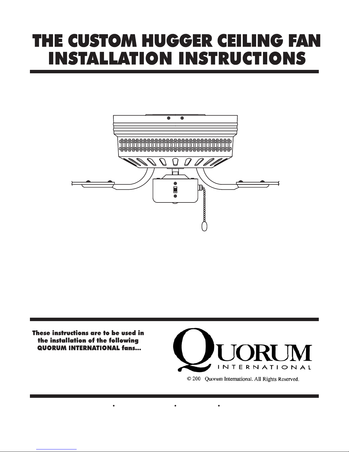
Please read and save these instructions
7
P.O.Box 961008 Fort Worth, TX 76161 (817) 626-5483 FAX (817) 626-5540
IO149-02/07
The Custom Hugger
Page 2
This warranty gives you specific legal
rights, and you may also have other rights
which vary from state to state.
WHAT IS COVERED-
Except as specified below, the manufacturer
of this product warrants it to be free of all
defects in workmanship and material.
WHAT IS NOT COVERED BY THIS
WARRANTY-
1. All costs of removal or reinstallation
of the fan.
2. Damage resulting from failure to
follow instructions contained herein.
3. Damage occurring during shipment of
the product (claims must be presented to
the carrier).
4. Damage resulting from accident,
misuse, abuse, or neglect.
5. Damage resulting from the application
of any exterior coating, or by the addition
of any unapproved accessories.
6. Damage resulting from repair or
attempted repair by anyone other than the
manufacturer.
7. Damage resulting from causes other
than product defects, including lack of
1. Most problems can be handled by our
customer service agents over the
telephone. Customers seeking warranty
repair or replacement for any fan or
component are encouraged to call us for
assistance. All returns must be issued a
Return Goods Authorization number
(RGA) prior to returning the defective
unit or part. Call (817) 626-5483 Monday thru Friday 8:00 a.m. - 5:00 p.m.
CST to obtain a RGA number.
2. Arriving shipments will be refused if
they do not bear a valid RGA number on
the outside packaging.
3. A dated proof of purchase must
accompany any fan or component clearly
indicating the name of the original
purchaser.
4. To avoid damage in transit, the
product should be returned in its original
box and packaging. Quorum will not bear
responsibility for any shipping damage.
5. Any return of a fan or component
must be shipped freight and insurance
prepaid.
Complete and mail the enclosed
warranty card within 10 days to ensure
your warranty is registered.
If you have any questions regarding the
warranty, or the procedures for
obtaining service, please call us at
(817) 626-5483 - Monday thru Friday
8:00 a.m. - 5:00 p.m. CST.
technical skill, competence, or experience
of the user.
8. Glass or acrylic components or
accessories.
9. Minor occurrences of wobble are
accepted as normal and should not
necessarily be considered a defect.
WHO MAY ENFORCE WARRANTY-
This warranty may be enforced only by
the original purchaser. The end user must
possess a dated proof of purchase from an
authorized Quorum dealer to establish a
warranty claim.
LENGTH OF THE WARRANTY -
1. For the fan motor - for the lifetime of
the original purchaser.
2. For everything else, except blades and
finish - one year from the date of
purchase.
3. For fan blades and finish - 90 days
from the date pf purchase.
WHAT WE WILL PAY FOR -
We agree to correct defects outlined in the
warranty without charge, or at our option
replace the fan with an equivalent or
superior product if the defective unit is
returned prepaid to us.
TO GET WARRANTY SERVICE -
To obtain warranty service, the product
must be returned prepaid to Quorum.
(This warranty is not enforceable outside
the United States.) Details regarding
return shipment are explained elsewhere
in this manual. Whenever warranty
service is required, you must present a
copy of the original dated sales receipt as
proof of coverage.
There is no other express warranty.
Quorum hereby disclaims any and all
implied warranties, including but not
limited to those of merchantability of
fitness for a particular purpose to the
extent permitted by law. Quorum shall
not be liable for incidental,
consequential, or special damages
arising out of or in connection with the
product use or performance except as
may otherwise be accorded by law. The
duration of any implied warranty which
cannot be disclaimed is limited to the
periods specified above in the express
warranty.
EXTENDED WARRANTY SERVICE
An extended warranty which applied to all parts except the fan motor (which is covered by the lifetime
warranty) is available. This coverage allows free parts replacement for any such components for the lifetime
of the original owner of the fan. Indicate your desire for this added coverage on the warranty reply card and
mail, along with $11.50 to Quorum. We will acknowledge your registration for this coverage.
FOR YOUR RECORDS
Purchased From
City State
Fan Model No.
Date Purchased
Page 3
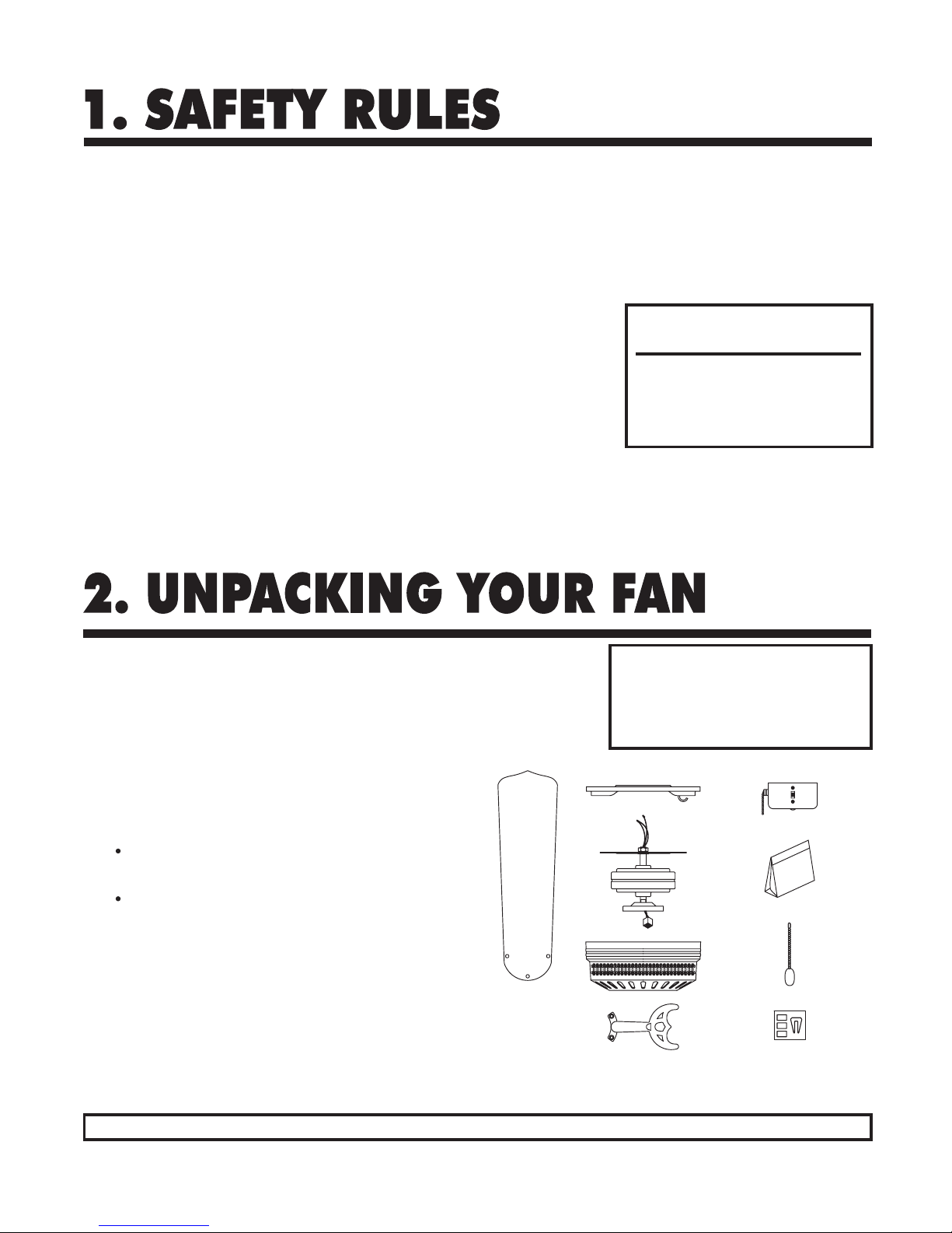
Model #11525-xx: 14.52 lbs
1. Set of blades (a)
2. Hanger/mounting plate (b)
3. Fan motor assembly (c)
4. Motor housing (d)
5. Set of blade arms (e)
6. Control cup (f)
7. Parts bags (g) containing:
Blade attachment hardware
(Screws/washers, washers may be
attached to screws)
Mounting hardware (wire nuts, wood
screws,
machine
screws, lock washers,
spring washers, metal washers
.)
8. Pull chain knob (h)
9. Blade balancing kit (i)
Unpack your fan and check the contents. Do not discard the carton. If warranty
replacement or repair is ever necessary the fan should be returned in original packaging.
Remove all parts and hardware. Do not lay motor housing on its side - because the
decorative casing may shift. Check all visible screws, bolts and nuts for tightness.
Examine all parts. The following parts should be included:
NOTE:
Some Quorum fan models will have slightly
different parts than what is shown here
depending upon the design you have chosen.
Basic installation procedures are similar for
all models.
IF YOU FIND THAT PARTS ARE MISSING. CONT ACT YOUR DEALER FOR REPLACEMENT, OR CALL QUORUM DIRECTLY AND WE WILL MAIL REPLACEMENTS TO YOU IMMEDIATELY .
a.
b.
c.
d.
e.
f.
g.
h.
i.
1. To avoid possible electric shock, turn
off the electricity at the main fuse box or
circuit panel before you begin the fan
installation or before servicing the fan or
installing accessories.
2. Read all instructions and safety
information carefully before installing
your fan and save these instructions.
3. Make sure all electrical connections
comply with local codes or ordinances as
well as the National Electrical Code. If
you are unfamiliar with electric wiring,
please use a qualified and licensed
electrician.
4. Make sure you have a location
selected for your fan which allows clear
space for the blades to rotate, and at lease
seven (7) feet of clearance between the
floor and the fan blade tips.
5. The outlet box and ceiling support
joist used must be securely mounted, and
capable of supporting at least 50 pounds.
To reduce the risk of fire, electric shock,
or personal injury, use only an outlet box
clearly labeled "Acceptable For Fan
Support".
6. To reduce the risk of personal injury
use only approved hanging brackets and
screws supplied with the outlet box for
mounting to the outlet box.
7. After installation is complete, check
that all connections are absolutely secure.
8. Do not insert anything into the fan
blades while they are rotating.
9. Do not operate the reverse switch until
the fan has come to a complete stop.
10. Do not attempt to control the
operation of the fan (or an optional light
kit) from any wall control that is not
approved by Quorum for use with its fans.
Do not use solid state wall controls. The
use of any unapproved control voids the
fan's warranty.
TOOLS REQUIRED
FOR INSTALLAITON
Phillips Screwdriver
Wire Cutters
Electrical T ape
Step Ladder
11425-xx: 9.46 lbs
Page 4
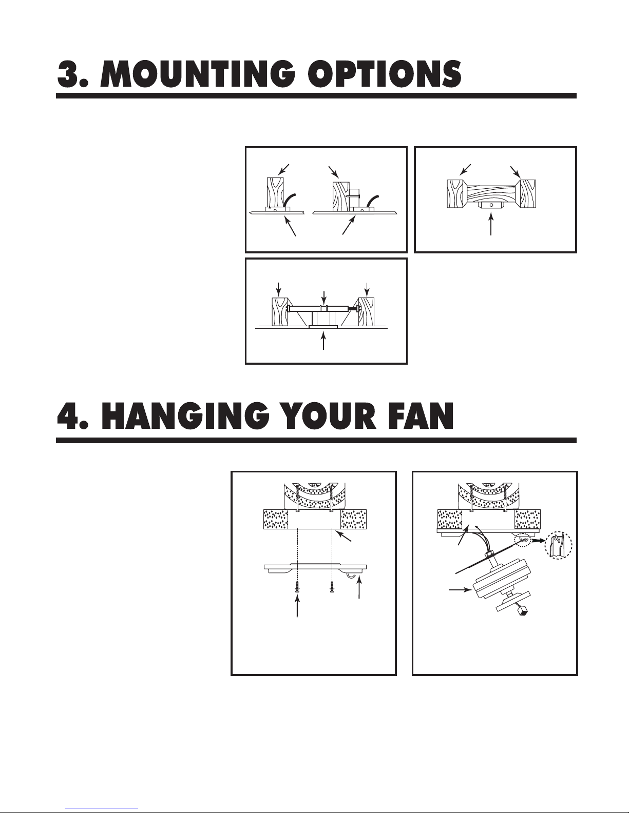
1. Disconnect the power by removing fuses
or turning off circuit breakers.
2. If there is an existing outlet box, ensure it
is clearly marked "Suitable for Fan Support".
If it is not so marked, it must be replaced
with an approved one.
3. Secure the outlet box (or make sure the
existing box is secured) directly to the
building structure. Use appropriate fasteners
and building materials.
4. Figures 1 and 2 are examples of different
ways to mount the outlet box in different
situations.
5. To hang the fan in locations where no
ceiling joist is available, a hanger support bar
may be required (Figure 4). Quorum
distributes approved hanger support bars and
outlet boxes.
WARNING: TO REDUCE THE RISK OF ELECTRIC SHOCK, FIRE, OR PERSONAL INJURY,
MOUNT THE FAN ONLY TO AN OUTLET MARKED ACCEPTABLE FOR FAN SUPPORT AND USE
MOUNTING SCREWS PROVIDED WITH THE OUTLET BOX.
Fig. 1 Fig. 2
Fig. 3
Ceiling Joists Ceiling Joists
Ceiling Joist
Hanger
Support Bar
Ceiling Joist
Outlet Boxes
Outlet Boxes
Outlet Boxes
WARNING -Turn off the power!
DO NOT fasten the blades to the fan until it is
assembled and hanging from the ceiling. To do
so now will likely bend the blade arms and
almost certainly cause wobble.
1. Secure the mounting plate to the outlet
box (Fig. 4) using the steel machine screws
or mount it directly to the ceiling joist using
the long wood screws supplied with the fan.
2. Pull the building wires though the center
hole in the mounting plate.
3. (Fig. 5) Lift the fan motor without the
blades, and engage the hole of motor plate
with the hook on the mounting plate. Let the
motor hang temporaily while safety making
the wiring connections.
Fig. 5
Screws
Hanger/
mounting
plate
Fan motor
Outlet box
Outlet box
Fig. 4
Page 5
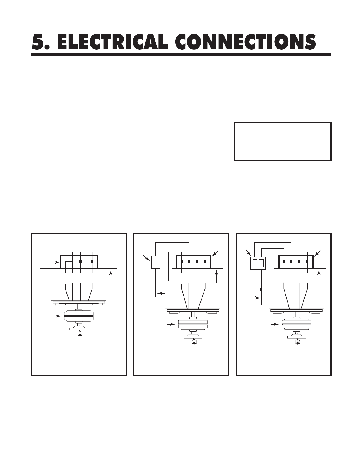
Fig. 6 Fig. 6a Fig. 6b
Outlet box
Fan switch
on wall
Ceiling
REMEMBER -Turn off the power!
WH
BLUE
BLK
WH
BLK
House
supply
wire
GROUND
GRN
4. Optional Wall Controls:
Wiring connections for optional wall
control are shown in Fig. 6a and 6b. Figure
6a shows how to wire a fan wall control
switch. This controls the fan only. To
separately control an optional light kit
using the light kit pull chain, you would
have to connect the blue wire from the fan
to the house supply wire, before it goes to
the wall control. This is not an easy
connection, and we suggest you call a
qualified electrician to do it for you.
5. Inside the ceiling junction box be sure
to spread the wires apart so that the black
and blue connections are on one side of
the outlet box and the white/white and
green/ copper connections are on the other
side.
Use the wire nuts supplied with your fan
when making connections. Secure the
connectors with electrical tape and make
sure there are no loose connections or wire
strands.
1. Spread the wires apart so that the black
and blue wires from the fan are on one
side of the mounting bracket and the white
wire and green ground wire are on the
other side.
2. Connect the green wires from the
mounting plate and the motor plate to the
copper building ground wire
3. (Fig. 6) Connect the BLACK building
supply wire to the BLACK and BLUE fan
wires. Connect the WHITE building
neutral wire to the WHITE fan neutral
wire. Connect the COPPER building
ground wire to the GREEN fan ground
wire.
Use ONLY wall controls approved by
Quorum. Use of unapproved wall
controls will cause unacceptable
humming noise, and avoids the fan
warranty.
Outlet box
Ceiling
WH
BLUE
BLUE
BLUE
BLK
WH
BLK
BLKBLK
GROUND
GRN
Fan/light
switch
on wall
House
supply
wire
Outlet box
Ceiling
WH
BLUE
BLUE
BLUE
BLK
WH
BLK
BLK
BLKBLK/WH
GROUND
GRN
Fan
Fan Fan
Page 6
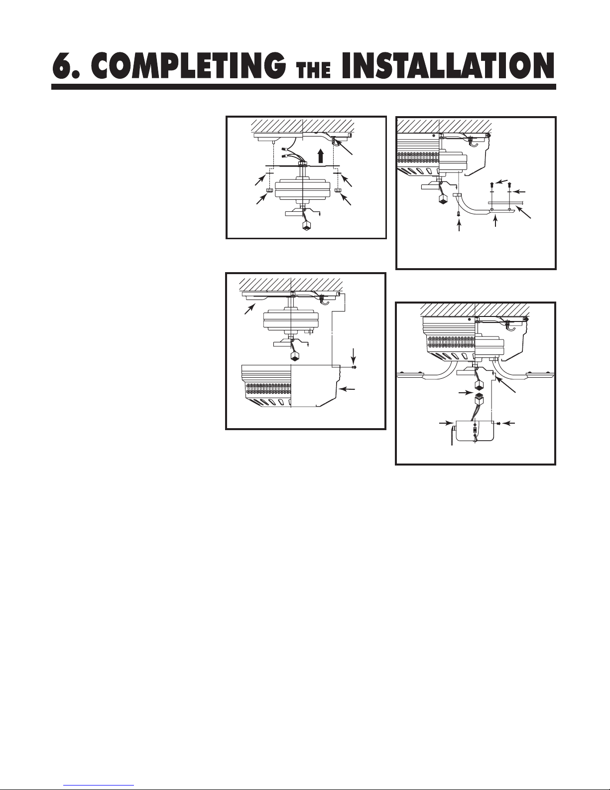
1. Make sure the wiring is safely inside the
outlet box as instructed in Step 5 -
Electrical Connections.
2. Attaching the motor (Fig. 7)
Match the four holes at both ends of the
mounting bracket with the four screws of
the mounting plate. Secure the fan assembly
to the mounting plate using washers and
nuts. See illustration.
3. Attaching the motor housing (Fig. 8)
Place the motor housing on the motor.
Firmly tighten the three or four screws
holding the housing to the mounting plate to
avoid noise and vibration.
4. Blade Assembly & Installation (Fig. 9)
Using the supplied blade arm screws, attach
the blades to the blade arms. In some cases
the fiber washer is permanently fixed to the
screw head. Ensure all screws are used for
each blade. Next attach the blades to the
motor assembly using the supplied screws.
DO NOT bend the blade arms when
installing the blades.
5. Attaching the Control Cup (Fig. 10)
Snap together the cannon plug, attach the
control cup to the control cup plate with the
three (3) screws provided.
Fig. 8
Fig. 7
Fig. 10
Fig. 9
Nuts
Washers
Nuts
Washers
Screws
Motor
housing
Mounting
plate
Screws
Screws
Fiber
washers
Screws
Blades
Blade arms
Screws
Control
cup
Control
cup plate
Cannon plug
Page 7
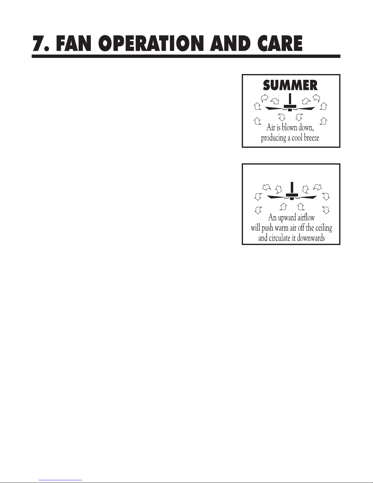
1. A ceiling fan is an environmentally
smart choice to cool as well as to help
warm your home or office. Adjust your
HVAC thermostat during fan use to save
additional energy and money on your air
conditioning and heating utility bills. You
should see a significant reduction in both
your heating and cooling costs by regular
use of your fan.
Do not hesitate to use your fan during
summer and winter months. In summer,
(Fig. 11) using the reverse switch, adjust
the fan's direction so cool air is blown
down, producing a cooling breeze. In
winter, (Fig. 12) reverse the fan so that an
upward airflow will push warm air off the
ceiling and circulate it downwards into
the living area. In winter months, use the
fan at a lower speed than summer.
2. Periodically check tightness of all
screws securing the blades to the blade
arm attachment points. A clicking or a
rattling noise is a sure indication of
loosening screws. Since screws will
invariably work loose over time, at least
once a year, tighten all the screws
attaching blades to blade arms. Do not
bend blade arms when cleaning or
servicing the fan.
3. If a light kit is attached to the fan,
likewise check that all screws attaching
glass to metal fitters are finger tight. Do
not use a screwdriver or pliers to tighten
glass screws.
4. Clean you fan periodically using only
a cloth dampened with a mild detergent
solution for all hardware - never use
solvents. The finish plating is lacquered
to prevent tarnishing. Use a lint-free
cloth with clean water to clean blades.
5. You will never need to oil or lubricate
your fan. Its permanently sealed bearings
will provide trouble free, silent operation
for many years.
6. If repairs or servicing are ever
required, to avoid possible electric shock,
turn off the electricity at the main fuse
or circuit panel before you begin.
7. If an optional fan speed wall control is
used with your fan-using the pull chain,
put the fan speed on HIGH and leave at
that setting. The fan's speed can be
adjusted from the wall control.
Fig. 12
Fig. 11
WINTER
Page 8
FAN WILL NOT START
1. Check that the electricity has been
turned on at the circuit breaker which had
probably been turned off during
installation.
2. Turn off the electricity. Check all
connections in the wiring of the fan at the
ceiling and make sure it follows the
wiring instructions outlined in this
manual.
NOISE
Note: Always allow a day or two "run-in"
time for any new fan at medium or high
speed. When attempting to diagnose
noise, listen carefully from several sides
to try and isolate the location of the noise
(blade, upper end, motor, light kit, etc.)
1. Tighten all screws attaching blades to
blade arms. Remember to tighten these
screws at least once a year because they
may loosen slowly over time and cause a
clicking noise.
2. Turn off the power. Loosen the
canopy and check that the wiring and/or
wire nut connectors are not resting against
the canopy, possibly vibrating while the
fan is on.
3. Use of a standard light rheostat or an
unapproved fan wall control to control the
fan speed will always cause an annoying
"hum". Many fan motors do not work
quietly with solid state variable speed
controls.
4. Check that the rubber gasket on the
mounting bracket has been installed if
called for in the installation instructions.
5. Check that the canopy is not touching
the ceiling.
6. Check that all screws on the motor
housing and the bottom housing are tight.
FAN TURNS, BUT DOES NOT MOVE
MUCH AIR
1. The fan may be running in reverse.
2. The distance from the ceiling to the
blades may be too small. At least 8" are
recommended.
3. The room may contain items which
obstruct the air flow.
4. The fan may be too small for the size
of the room.
EXCESSIVE WOBBLE
Note: A small amount of wobble is
considered acceptable and should not be
considered a defect.
1. Make certain all blades are tightly
attached to each blades' respective blade
arm.
REPLACEMENT PARTS AVAILABLE
A full range of genuine replacement
spare parts are available at reasonable
cost directly form Quorum
International. Please call us at (817)
626-5483. Monday through Friday
from 8:00 A.M. to 5:00 P.M. CST.
 Loading...