

Page 1
Assembly Instruction Sheet #IS-TRG8701OZ
For Style TRG8701OZ
Quoizel, Inc.
6 Corporate Parkway
Goose Creek, SC 29445
Customer Service
Phone 631.273.2700
Fax 631.231.7102
www.quoizel.com
ToolsRequired: Flatheadscrewdriver, Phillipsscrewdriver,pliers,wire cutters, wire strippers, electricaltape,
safetyglasses.
BulbRecommended:
EstimatedAssembly Time:
Preparation:
belowto be sure all partsarepresent. If any parts aremissing or damaged, do not attemptto assemble, install, or
operatethe fixture. Contact customer serviceforreplacement parts.
Fixturecan only be mounted inthedirection indicated on page 2.
Identifyand inspect all parts beforebeginninginstallation. Check package content listand diagrams
(1)Medium Base Decorative Filament 60Wbulbs(provided), Maximum 100W,Alternate
bulb(1) 23W CFL Maximum.
30-45minutes
Warnings and Cautions
Turn off electricity at circuit breaker or main fuse box before installation. Consult a licensed electrician if in doubt.
These instructions are provided for your safety. It is very important you read them completely before installing the fixture. We strongly
recommend that a licensed, professional electrician perform the installation.
Disconnect fixture from power source before replacing bulbs. Make sure bulbs are given sufficient time to cool before removal. Do not subject
glass parts to any shock while in operation or shattering may result.
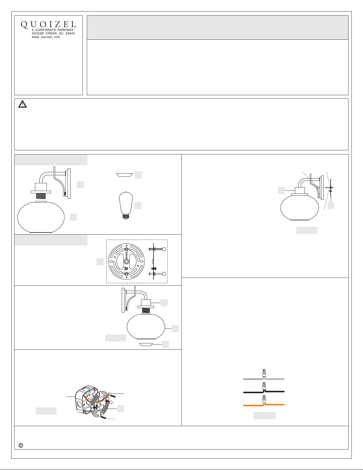
Package Contents
Socket Collar
C
x1
Bulb
D
x1
B
A
Shade
x1
Fixture Body
x1
Hardware Contents
Crossbar Assembly
STEP 1 Install Shade-
A. Place Shade (B) over the Socket, secure
by threading Socket Collar (C) onto
Socket. Hand tighten until sung.
STEP 2 Install Inner Backplate-
A. Pass the supply wires through the Crossbar Assembly (AA). Attach
the Crossbar Assembly (AA) to the Outlet Box with the head of the
Green Ground Screw facing you. Secure it with Outlet Box Screws
(not included). Tighten until snug.
Outlet Box
Figure 2
x1
AA
A
Figure 1
C
Supply Wires with
Ground Wire
AA
Outlet Box Screws
(not included)
STEP 3 Fit Fixture Body to
A. Remove mounting balls from the
STEP 4 - Wire Connections
A. Use standard wire connectors (not included) to make all wire
B. Connect White Supply Wire from the Outlet Box to Ribbed side Wire
C. Connect Black (or Red) Supply Wire from the Outlet Box to Smooth
B
D. Connect Ground Wire from the Outlet Box to Ground Wire from
E. Twist connectors until wires are tightly joined together.
F. Wrap each connection with approved electrical tape and carefully
-
Crossbar Assembly
Crossbar Assembly (AA). Fit the
Fixture Body (A) Crossbar
Assembly (AA) and secure with
mounting balls. Note: The
backplate of the Fixture Body (A)
should be snug against the wall
surface and the mounting balls. If
not, adjust the length of the nipple
on the CrossbarAssembly (AA) by
unscrewing the preassembled hex
nut and lock washer and then
screwing the mounting screws in or
out of the crossbar until the correct
length is achieved. Once the
backplate of the Fixture Body (A) is
secure, remove the mounting ball
and Fixture Body (A) and proceed
to Step 4.
connections. (Connectors are not included with fixture.) Strip and
prepare wire ends according to instructions supplied with
connectors.
from fixture.
side Wire from fixture.
fixture.
stuff all the connected wires into the Outlet Box.
White wire
from supply
Black wire from
supply (or Red)
Ground wire
from supply
Figure 4
Mounting
Ball
A
Ribbed side wire
from fixture
Smooth side wire
from fixture
Ground wire
from fixture
Hex Nut and
Lock Washer
AA
Mounting
Screw
Figure 3
2014 QuoizelInc.
Need assistance with parts or assembly? Call Quoizel customer service at 1-631-273-2700
Thank you for purchasing a Quoizel product.
or visit us on-line at www.quoizel.com
1of2
March2014
Page 2
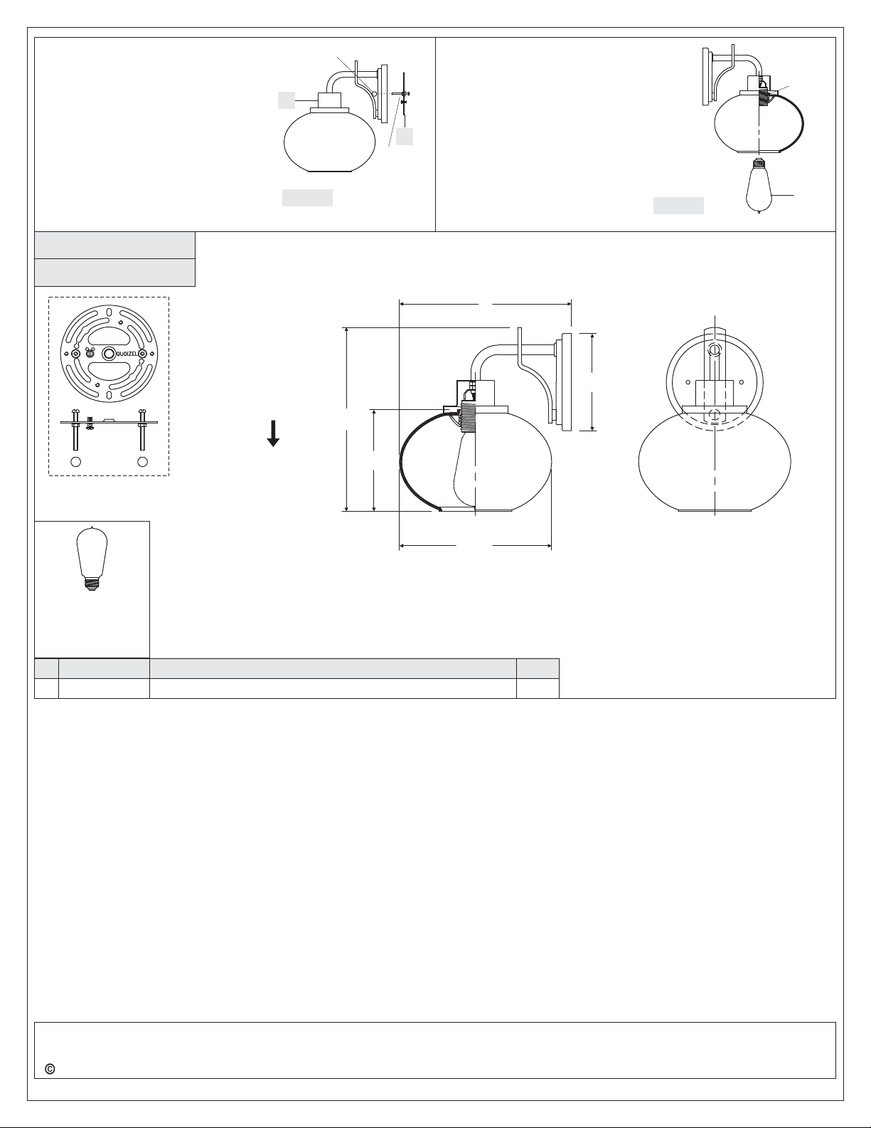
STEP 5 Install Fixture Body-
A. Carefully tuck all wires into the outlet
box and position the backplate of
Fixture Body (A) over the outlet box.
Align the holes in the backplate with
the mounting screws. Place caulk (not
supplied) into the previously removed
mounting balls and then attach Fixture
Body (A) using the mounting balls.
Hand tighten until snug.
TRG8701OZ
FINISH: OLD BRONZE
Mounting
Ball
A
Figure 5
AA
Mounting
Screw
STEP 6 Install Bulb-
A. This fixture uses standard bulb 60W
(supplied) with a standard screw base.
Maximum 100 watts.
B. Insert bulb and screw properly into place.
Your fixture is now assembled and ready to
use. Enjoy!
Figure 6
9”
Socket
Bulb
(1)Medium Base
Decorative
Filament 60W
bulbs (provided),
Maximum 100W.
PART NUMBER
NO.
1
Fixture can only be
mounted in the
direction indicated
9.5”
5”
8” Dia.
NOTE: ALL DIMENSIONS ARE ROUNDED UPTO THE NEAREST 1/2"
REPLACEMENT PART DESCRIPTION
REQ.
5” Dia.
2014 QuoizelInc.
Need assistance with parts or assembly? Call Quoizel customer service at 1-631-273-2700
Thank you for purchasing a Quoizel product.
or visit us on-line at www.quoizel.com
2of2
March2014
 Loading...