

Quoizel SNNL9009K, SNNL9009PN Assembly Instruction Sheet

6 CORPORATE PARKWAY
GOOSE CREEK SC 29445
www quoizel com
..
,.
Assembly Instruction Sheet #IS-SNNL9009
For Styles SNNL9009K and SNNL9009PN
Pleasegoto forproductcleaning tips. Go tothe selection.
ToolsRequired: Flathead screwdriver,Phillips screwdriver,pliers, wire cutters, wirestrippers,electrical tape, safety glasses.
LightSource:
EstimatedAssembly Time:
Preparation:
present.Ifany parts are missingordamaged, do not attempttoassemble, install, or operatethefixture. Contact customer serviceforreplacement
parts.
www.quoizel.com Care+Maintenance
LED16W
20-30minutes
Identifyandinspect all parts beforebeginninginstallation. Check package contentlistand diagrams below tobesure all parts are
Warnings and Cautions
Turn off electricity at circuit breaker or main fuse box before installation. Consult a licensed electrician if in doubt.
These instructions are provided for your safety. It is very important you read them completely before installing the fixture. We strongly
recommend that a licensed, professional electrician perform the installation.
Disconnect fixture from power source before replacing bulbs. Make sure bulbs are given sufficient time to cool before removal. Do not subject
glass parts to any shock while in operation or shattering may result.
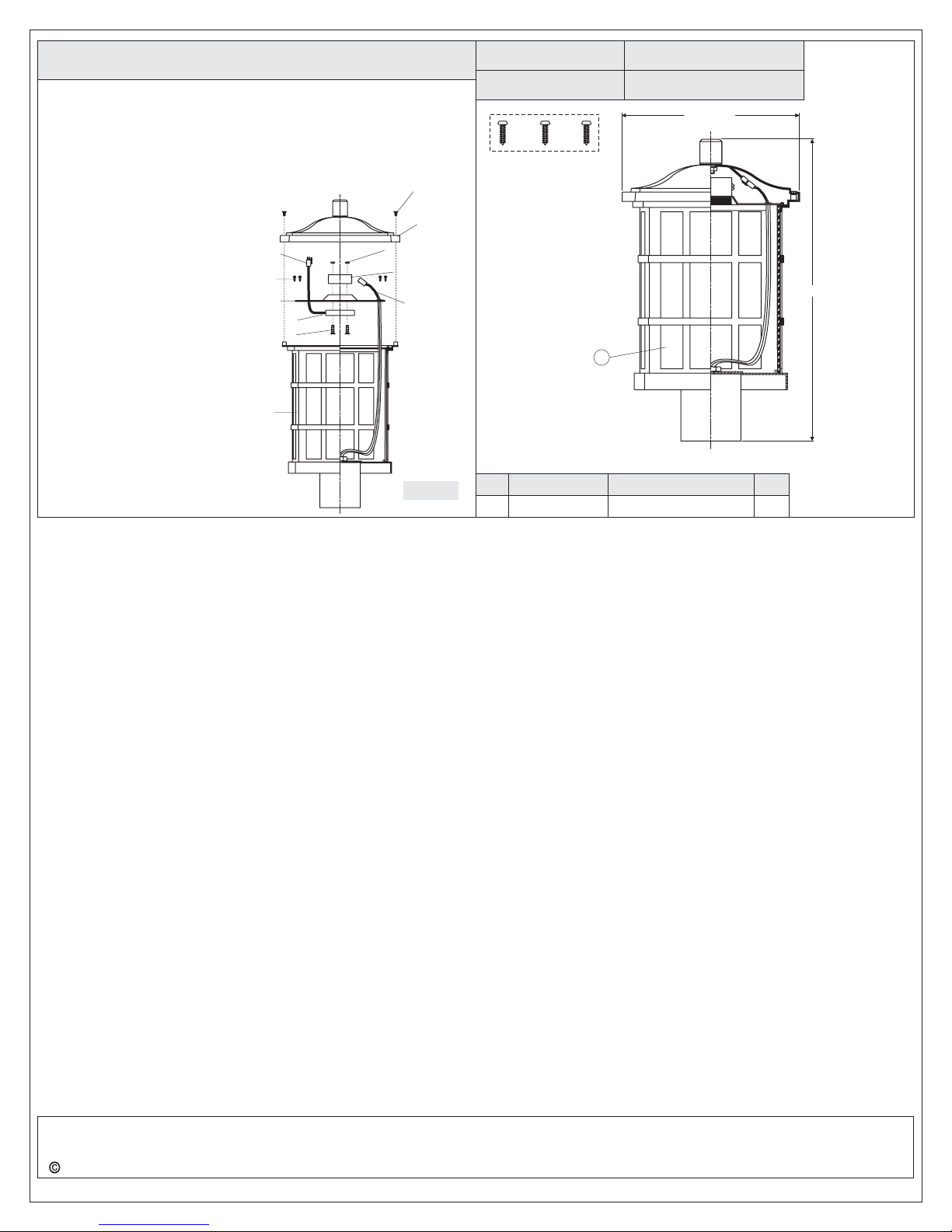
Package Contents
Mounting
Screw
A
x3
Fixture Body
STEP 1 Drill Pilot Holes on Post-
A. Carefully fit the Post Fitter over the
end of the Post (not supplied),
making sure the Post Fitter is fully
seated.
B. Mark the drill point for the (3)
Mounting Screws, using (3)
Mounting Holes as reference. After
marking hole locations, remove
fixture from post and drill 1/16” pilot
holes for screws.
STEP 2 - Wire Connections
A. Use standard wire connectors (not included) to make all wire
connections. (Connectors are not included with fixture.) Twist
connectors until wires are tightly joined together. Wrap each
connection with approved electrical tape and carefully stuff all the
connected wires into the Outlet Box.
White wire
from supply
Black wire from
supply (or Red)
Ground wire
from supply
STEP 3 - Attach Fixture Body to Post
x1
B
Figure 1
Post Fitter
Mounting Hole
Post
White wire
from fixture
Black wire
from fixture
Ground wire
from fixture
Figure 2
(Step 3 Continued)
completely, aligning the holes in
the Fitter with the 1/16” Pilot Holes
drilled into the Post.
B. Secure the Fixture to Post with (3)
Mounting Screws (A).
Your fixture is now assembled
and ready to use. Enjoy!
Figure 3
Post Fitter
Mounting Hole
Post
HOW TO REPLACE GLASS PANELS
Unlock Allen Screws on
A.
the
Fixture Hood and
remove the Fixture
Hood from the Cage.
B. Separate Quick
Connector and then
unscrew Screws from
the Cage and remove
LED Module and Heat
Sink, the Glass Holder.
Replace Glass Panels
from the Cage and then
re-install the Glass
Holder, LED Module
and Heat Sink. Secure
with removed Lock
Screws.
C. Connect Quick
Connectors. Attach the
Fixture Hood back onto
the Cage and secure
with Allen Screws.
Male Quick
Connector
Screw
LED Module
and Heat Sink
Glass
Panel
Allen Screw
Fixture
Hood
Female Quick
Connector
Glass
Holder
Cage
A. Coat the top 1” of the Post with Clear Silicone Caulk (not supplied)
and position the Post Fitter onto the Post. Be sure to seat it
Need assistance with parts or assembly? Call Quoizel customer service at 1-631-273-2700
2015 QuoizelInc.
Thank you for purchasing a Quoizel product.
or visit us on-line at www.quoizel.com
Figure 4
July2015
1of2
HOW TO REPLACE LED MODULE
Unlock Allen Screws on the
A. Fixture Hood. Remove the Fixture Hood
from Cage.
B. Separate Quick Connector and then unscrew Screws from the Cage
and remove LED Module and Heat Sink.
C. Unscrew Lock Screws on the LED Module. Replace the LED Module
with the replacement. Pass Lock Screws through the replacement
LED Module, the Heat
Sinks as shown and
thread Hex Nuts onto
Lock Screws to secure
them together. Hand
tighten until snug.
D. Pass the Quick
Connector from the LED
Module through the hole
on the Heat Sink.
E. Re-install LED Module
and Heat Sink onto the
top edge of the Cage.
Secure with Screws.
Connect Quick
Connectors. Attach
Cage with Glass Panels
back onto the Fixture
Hood and secure with
Allen Screws.
Male Quick
Connector
Screw
Heat Sink
LED Module
Lock Screw
Cage with
Glass
Panels
Allen Screw
Fixture
Hood
Hex Nut
Upper
Heat Sink
Female
Quick
Connector
Figure 5
SNNL9009K
FINISH: MYSTIC BLACK
NOTE: ALL DIMENSIONS ARE ROUNDED UP TO THE NEAREST 1/4"
PART NUMBER
PART NUMBER
NO.
1
G3729PA
FINISH: PALLADIAN BRONZE
1
REPLACEMENT PART
GLASS PANEL
SNNL9009PN
9.5” SQ.
16”
REQ.
4
Need assistance with parts or assembly? Call Quoizel customer service at 1-631-273-2700
2015 QuoizelInc.
Thank you for purchasing a Quoizel product.
or visit us on-line at www.quoizel.com
2of2
July2015
 Loading...