

Page 1
6 CORPORATE PARKWAY
GOOSE CREEK SC 29445
www quoizel com
..
Quoizel, Inc.
6 Corporate Parkway
Goose Creek, SC
29445
Customer Service
Phone 631.273.2700
Fax 631.231.7102
www.quoizel.com
,.
Assembly Instruction Sheet #IS-QF1397RWT
For Style QF1397RWT
ToolsRequired:Flatheadscrewdriver,Phillipsscrewdriver,pliers,wire cutters, wire
strippers,electricaltape,safety glasses.
BulbRecommended: (8) MediumBase60WMaximum
EstimatedAssemblyTime: 20-30minutes
Preparation:Identifyandinspect all partsbeforebeginninginstallation. Check package
contentlistanddiagrams below tobesureall parts arepresent.Ifany parts aremissing
ordamaged,donot attempt toassemble,install,or operate thefixture.Contactcustomer
serviceforreplacementparts.
Warnings and Cautions
Turn off electricity at circuit breaker or main fuse box before installation. Consult a licensed electrician if in doubt.
These instructions are provided for your safety. It is very important you read them completely before installing
the fixture. We strongly recommend that a licensed, professional electrician perform the installation.
Disconnect fixture from power source before replacing bulbs. Make sure bulbs are given sufficient time to cool
before removal. Do not subject glass parts to any shock while in operation or shattering may result.
A
G
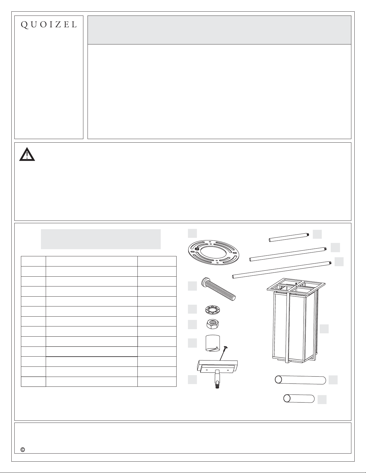
Package Contents
Part
A Crossbar
B
C
D
E
F
G
H
I
J
K
L
Description
Mounting Screw
Lock Washer
Hex Nut
Mounting Ball
Ceiling Canopy
6” Rod with Nipple
12” Rod with Nipple
24” Rod with Nipple
Socket Assembly
Long Candle Cover
Short Candle Cover
Quantity
1pc.
2 pcs.
2 pcs.
2 pcs.
2 pcs.
1pc.
2 pcs.
2 pcs.
1pc.
1pc.
4 pcs.
4 pcs.
B
C
D
E
F
J
K
H
I
Need assistance with parts or assembly? Call Quoizel customer service at 1-631-273-2700
2012 Quoizel Inc.
Thank you for purchasing a Quoizel product.
or visit us on-line at www.quoizel.com
1of7
L
December2012
Page 2
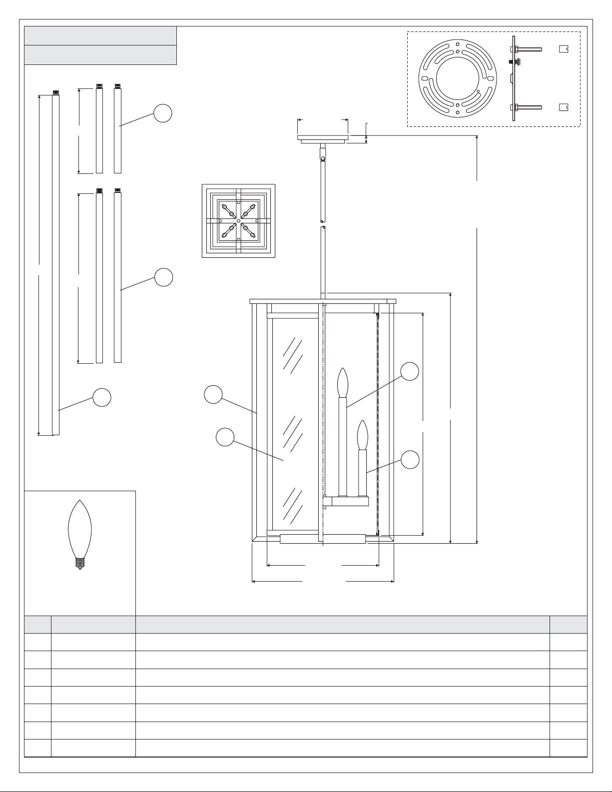
QF1397RWT
FINISH: WESTERN BRONZE
2.4mm
2.4mm
13Ga
13Ga
Q
Q
U
U
O
O
I
I
Z
Z
E
E
L
L
R
24”
6”
12”
7
5.5” Dia.
1”
90”
OVERALL HEIGHT INCLUDES
(2) 6” AND 12” RODS
(1)24”ROD
6
3
5
1
27.5”
24.5”
4
(8) 60W Candelabra
Base Bulbs
(No Supplied)
PART NUMBER
NO.
11397RWTQF
1
M2383CCWT
2
M2382CCWT
3
4
5
6
7
G3415PA
9024EXWT
9008EXWT
9007EXWT
12” Sq
15.5” Sq
NOTE: ALL DIMENSIONS ARE ROUNDED UP TO THE NEAREST 1/2"
REPLACEMENT PART DESCRIPTION
BASE QF1397RWT
CANDLE COVER WESTERN BRONZE 5.12"L
CANDLE COVER WESTERN BRONZE 10.75"L
PANEL GLASS CLEAR 11.65"W
ROD EXTENSION WESTERN BRONZE 0.63D" X 24"L
ROD EXTENSION WESTERN BRONZE 12"L X0.63"D
ROD 6"L X .63"DEXTENSION WESTERN BRONZE 0
2
REQ.
1
4
4
4
1
2
2
2of7
Page 3
6 CORPORATE PARKWAY
GOOSE CREEK SC 29445
www quoizel com
..
,.
Assembly Instruction Sheet #IS-QF1397RWT
For Style QF1397RWT
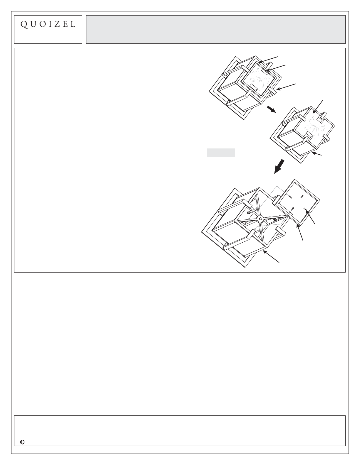
STEP 1 Remove Styrofoam inside of the Cage-
A. Place the Cage onto a flat working surface with the bottom
facing up. Remove the Ring from the bottom of the Cage
by unscrewing Lock Screws.
B. Remove Styrofoam inside the Cage.
C. Attach the Ring back onto the bottom of the Cage and
secure with Lock Screws. Hand tighten until snug.
Figure 1
Ring
Lock Screw
Cage
Styrofoam
Cage
Cage
Lock Screw
Ring
Thank you for purchasing a Quoizel product.
Need assistance with parts or assembly? Call Quoizel customer service at 1-631-273-2700
2012 Quoizel Inc. December2012
or visit us on-line at www.quoizel.com
3of7
Page 4

6 CORPORATE PARKWAY
GOOSE CREEK SC 29445
www quoizel com
..
,.
Assembly Instruction Sheet #IS-QF1397RWT
For Style QF1397RWT
STEP 2 Assemble Rods-
A. Determine the Rods (G/H/I) to be assembled to the
Socket Assembly (J) according to your hanging height.
B. Pass Supply Wires and Ground Wire through the chosen
Rods (G/H/I), then thread the chosen Rods (G/H/I) and the
Socket Assembly (J) together. Hand tighten until snug.
6” Rod with Nipple
6” Rod
with Nipple
12” Rod
with Nipple
24” Rod
with Nipple
12” Rod
with Nipple
Supply Wire and
Ground Wire
STEP 3 Assemble Ceiling Canopy to Upper
-
Rod
A. Pass Supply Wires and Ground Wire through the Ceiling
Canopy (F) and then thread the Ceiling Canopy (F) and
the Upper Rod together. Hand tighten until snug.
Socket
Assembly
Figure 2
Ceiling
Canopy
Supply Wire and
Ground Wire
Upper Rod
Figure 3
Need assistance with parts or assembly? Call Quoizel customer service at 1-631-273-2700
2012 Quoizel Inc.
Thank you for purchasing a Quoizel product.
or visit us on-line at www.quoizel.com
4of7
December2012
Page 5

6 CORPORATE PARKWAY
GOOSE CREEK SC 29445
www quoizel com
..
,.
Assembly Instruction Sheet #IS-QF1397RWT
STEP 4 - Attach Mounting Screws, Lock
Washers and Hex Nuts to Crossbar
For Style QF1397RWT
A. Line up a set of holes on the Crossbar (A) and Holes on
the Ceiling Canopy (F).
B. Thread Mounting Screws (B) into the holes on the
Crossbar (A), pass Lock Washers (C) and thread Hex Nut
(D) onto the Mounting Screws (B). Hand tighten until
snug.
STEP 5 - Attach Crossbar to Outlet Box
A. Attach the Crossbar (A) to Outlet Box and secure by
threading Outlet Box Screws (not supplied) into the
Mounting Holes on the Outlet Box. Tighten until snug.
Mounting Screw
Lock Washer
Ceiling
Canopy
Mounting
Hole
Crossbar
Hex Nut
Figure 4
Outlet
Box
Crossbar
Outlet Box
Screw
Figure 5
Thank you for purchasing a Quoizel product.
Need assistance with parts or assembly? Call Quoizel customer service at 1-631-273-2700
2012 Quoizel Inc. December2012
or visit us on-line at www.quoizel.com
5of7
Page 6

6 CORPORATE PARKWAY
GOOSE CREEK SC 29445
www quoizel com
..
,.
Assembly Instruction Sheet #IS-QF1397RWT
For Style QF1397RWT
STEP 6 - Attach Lanyard
A. The purpose of the lanyard is to provide the installer a
means to support the fixture from the junction box while
connecting the electrical wires. This enables the fixture
to hang from the junction box and your hands are free to
make the wire connections.
B. Turn the Button Stop so it may be inserted into the
crossbar slot. Make sure the Button Stop is completely
inside the crossbar. Slowly release the fixture to make
sure it is supported by the Button Stop. Proceed to the
wiring steps. Once you are complete with the wiring there
is nothing to do with Lanyard. The Lanyard will push into
the junction box when the fixture is placed for final
mounting.
STEP 7 Make Wire Connections-
A. Use standard wire connectors to make all wire
connections. (Connectors are not included with fixture.)
Strip and prepare wire ends according to instructions
supplied with connectors.
B. Connect White Supply Wire from the Outlet Box to White
Wire from fixture.
C. Connect Black (or Red) Supply Wire from the Outlet Box
to Black Wire from fixture.
D. Connect Ground Wire from the Outlet Box to Ground
Wire from fixture.
E. Twist connectors until wires are tightly joined together.
F. Wrap each connection with approved electrical tape and
carefully stuff all the connected wires into the Outlet Box.
Crossbar
Slot
Button Stop
Lanyard
Figure 6
Figure 7
White wire from supply White wire from fixture
Black wire from supply
(or Red)
Ground wire from supply Ground wire from fixture
Black wire from fixture
Figure 8
Thank you for purchasing a Quoizel product.
Need assistance with parts or assembly? Call Quoizel customer service at 1-631-273-2700
2012 Quoizel Inc. December2012
or visit us on-line at www.quoizel.com
6of7
Page 7

6 CORPORATE PARKWAY
GOOSE CREEK SC 29445
www quoizel com
..
,.
Assembly Instruction Sheet #IS-QF1397RWT
For Style QF1397RWT
STEP 8 - Attach Ceiling Canopy to Mounting
Screw
A. Place the Ceiling Canopy (F) over the Mounting Screws
(B) and secure with Mounting Balls (E). Hand tighten
until snug.
Mounting Screw
Ceiling Canopy
STEP 9 Attach Candle Cover-
A. Place Short Candle Cover (L) and Long Candle Cover (K) to
Socket.
Figure 9
Short Candle
Cover
Long Candle
Cover
Socket
Figure 10
Mounting Ball
STEP 10 Install Bulb-
A. This fixture uses candelabra bulbs with a screw base.
Maximum 60 watts.
B. Insert bulb and screw properly into place.
Your fixture is now assembled and ready to use.
Enjoy!
Thank you for purchasing a Quoizel product.
Need assistance with parts or assembly? Call Quoizel customer service at 1-631-273-2700
2012 Quoizel Inc. December2012
or visit us on-line at www.quoizel.com
7of7
Bulb
Socket
Figure 11
 Loading...