

Quoizel PO9140 Series Installation Manual
Installation Guide #IS-PO9140
For Style PO9140XX
Pleasegoto forproductcleaningtips.Gotothe selection.
ToolsRequired: Flathead screwdriver,Phillipsscrewdriver,Shovel, Electrical tape, Wire cutter,Safetyglasses,Wirestrippersandproperlength
wires(notincluded).
EstimatedAssembly Time:
Preparation:
present.Ifanypartsaremissingordamaged,donotattempttoassemble,install,oroperatethefixture.Contactcustomerserviceforreplacement
parts.
www.quoizel.com Care+Maintenance
30-45minutes
Identifyandinspectallpartsbeforebeginninginstallation.Checkpackagecontentlistanddiagramsbelowtobesureallpartsare
Warnings and Cautions
Turn off electricity at circuit breaker or main fuse box before installation. Consult a licensed electrician if in doubt.
These instructions are provided for your safety. It is very important you read them completely before installing the fixture. We strongly
recommend that a licensed, professional electrician perform the installation.
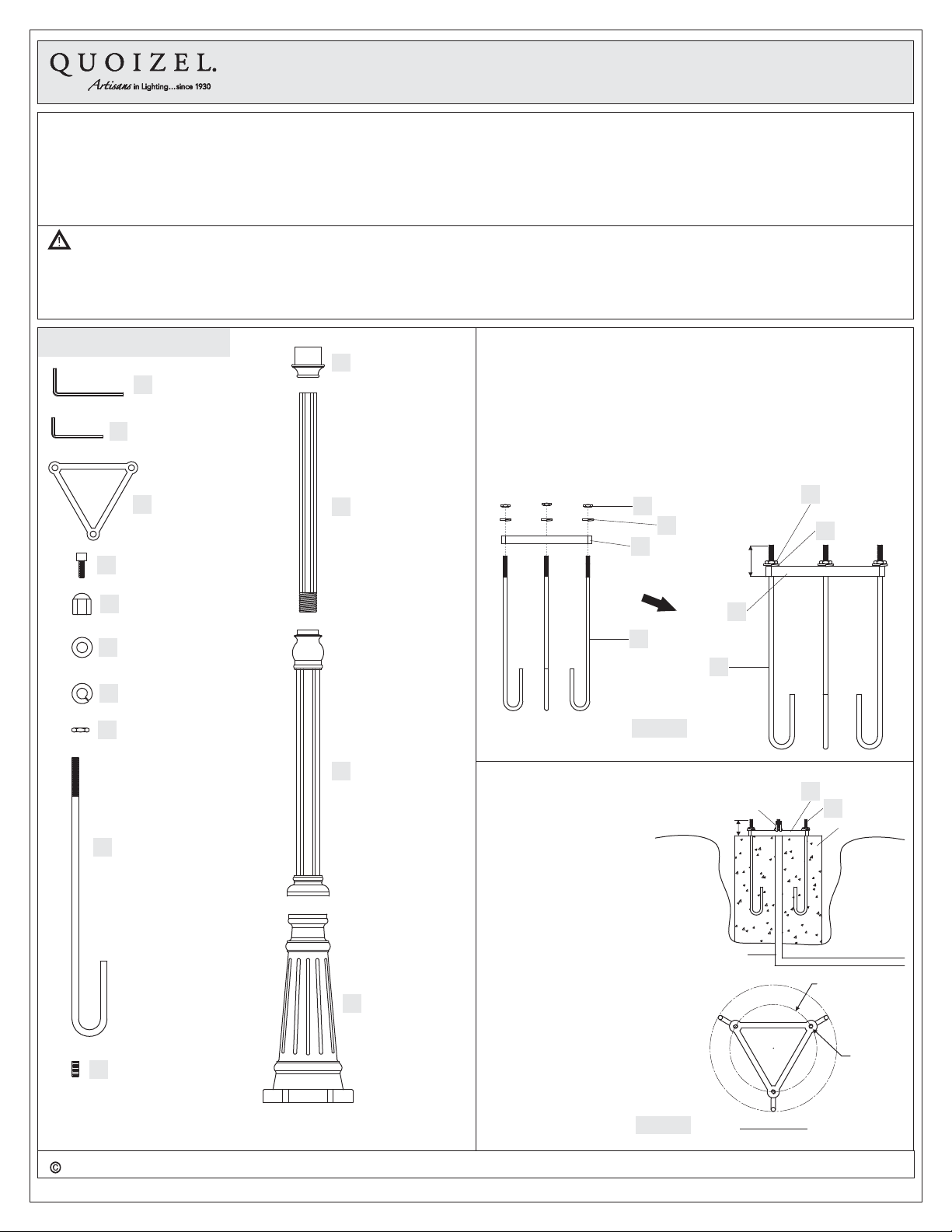
Package Contents
Big Allen Wrench
A
x1
Small Allen Wrench
B
x1
Anchor Bracket
C
x1
Allen Bolt
D
x3
Lock Ball
E
x3
Post Fitter
K
x1
Upper Post
L
x1
STEP 1 Assemble Anchor Bolts to the Anchor Bracket-
A. Remove all Spring Washers (G), Hex Nuts (H) and Lock Balls (E)
from theAnchor Bolts (I).
B. Screw the threaded end of each Anchor Bolt (I) in the Mounting
Bracket (C) making sure to that the Anchor Bolt (I) is 1.75” to 2”
extended from the bottom of the Bracket (C).
C. Place a Spring Washer (G) over the Anchor Bolt (I) and then thread
the Hex Nut (H) onto eachAnchor bolt (I). Securing the Bracket (C) in
place maintaining the 1.75”-2” length of the Anchor Bolt (I).
H
G
C
1.75” - 2”
C
H
G
Washer
F
x3
Spring Washer
G
x3
Hex Nut
H
x3
Anchor Bolt
I
x3
Allen Set Screw
J
x4
Middle Post
M
x1
Bottom Post
N
x1
I
Figure 1
STEP 2 Install Anchor
Bolts in the ground
A. At the desired location for
B. Use cement to secure the
-
the post a hole with a
minimum depth of 15” is
required for proper
installation of the post
mount. Please check with
local building codes as
local codes will always
supersede these
instructions.
Anchor Bolts (I) into the
ground making sure that
the Bracket (C) is flush on
top of the cement and level
Anchor at the desired
grade with the ground. This
is the base for the Post
Mount.
1.75” - 2”
Earth
Tube
I
Wires
C
I
Cement
Earth
Dia. 9”
Bolt
2018 Quoizel Inc.
visit us on-line atwww.quoizel.com
1of3
Figure 2
Bolt Circle
ReleasedDate:2018-10-09
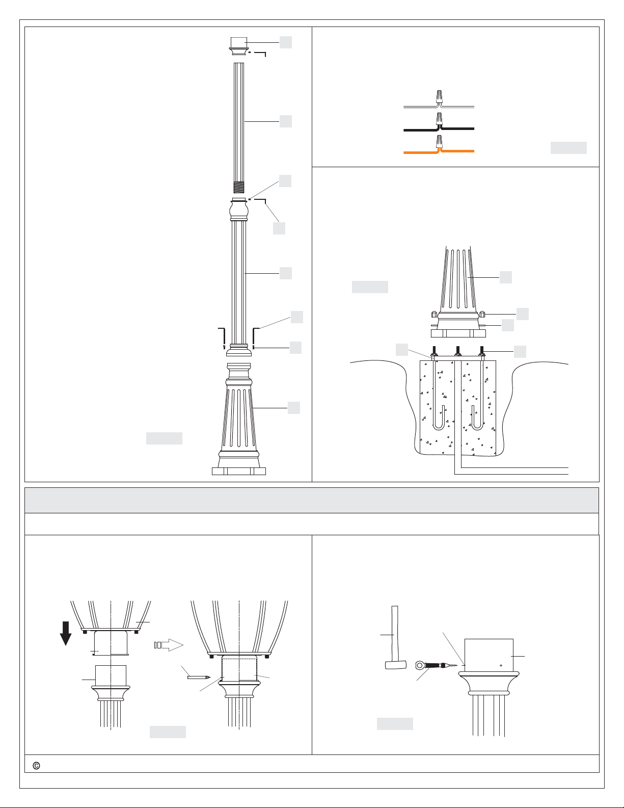
STEP 3 Assemble Post Fitter and Posts
together
A. Place the Post Fitter (K) on the Upper
B. Thread the Upper Post (L) assembly onto
C. Place the Middle Post (M) assemble onto
-
Post (L) end without the threads. Secure
the Post Fitter (K) with (2)Allen Set Screw
(J) using the SmallAllen Wrench (B)
provided.
the Middle Post (M) until secure. Secure
the Upper Post (L) assembly to the Middle
post (M) using (2)Allen Set Screw (J) and
the SmallAllen Wrench (B) provided.
the Bottom post (N) lining up the mounting
holes in the Middle Post (M) assembly
with the Bottom Post (N). Secure the
Middle Post (M) assembly to the Bottom
Post (N) using (2)Allen Bolt (D) and the
provide BigAllen Wrench (A). Tighten until
secure.
K
L
J
B
STEP 4 - Wire Connections
A. Use standard wire connectors (not included) to make all wire
connections. Twist connectors until wires are tightly joined together.
Wrap each connection with approved electrical tape and carefully
stuff all the connected wires into the Outlet Box.
White wire
from supply
Black wire from
supply (or Red)
Ground wire
from supply
STEP 5 - Install Post MountAssembly to Anchor Bolts
Place the Post Mount assembly onto the Anchor Bolts . Place a
A. (I)
Washer over eachAnchor Bolt and secure each Anchor Bolt
with the Lock Ball and tighten until secure.
Your installation is completed now. Restore electricity. Retain this
sheet for future reference.
(F) (I) (I)
(E)
White wire
from fixture
Black wire
from fixture
Ground wire
from fixture
Figure 4
M
Figure 5
A
Figure 3
D
N
Earth
C
INSTALL POST LIGHTING TO POST MOUNT
ToolsRequired: marking pen, 5/32” drill bit, center punch, hammer,drill,#10self-tappingscrew,and wrench.
STEP 1 - Mark the Location of the 3 Mounting Holes
A. Place the light fixture onto the post fitter and mark the location of
the 3 mounting holes on the fixture fitter onto the post fitter with the
marking pen.
STEP 2 M C E M H- arking the enter of ach ounting ole
A. Remove the light fixture. Using the center punch and hammer
marking the center of each mounting hole location that is marked
with the marking pen.
N
E
F
I
Earth
Post Fitter
2018 Quoizel Inc.
Post
Lighting
Marking Pen
Mounting
Hole
Figure 1
Hammer
Post
Fitter
visit us on-line atwww.quoizel.com
2of3
Center Punch
Marking
Post Fitter
Figure 2
ReleasedDate:2018-10-09
 Loading...