

Page 1
Installation Guide IS-PCCA2831EK#
For Style PCCA2831EK
Pleasegoto forproductcleaningtips.Gotothe selection.
ToolsRequired:
www.quoizel.com Care+Maintenance
Flatheadscrewdriver,Phillips screwdriver,pliers,wirecutters,wirestrippers,electricaltape,safetyglasses,markingpen,1/4”
drillbitanddrill.
LightSource:
FixtureHangingHeight:
EstimatedAssembly Time:
Preparation:
present.Ifanypartsaremissingordamaged,donotattempttoassemble,install,oroperatethefixture.
LED70W
MinimumHangingHeightis20”,MaximumHangingHeightis100”.
30-45minutes
Identifyandinspectallpartsbeforebeginninginstallation.Checkpackagecontentlistanddiagramsbelowtobesureallpartsare
MissingParts?Contactyouroriginalplaceof
purchase.
Warnings and Cautions
Turn off electricity at circuit breaker or main fuse box before installation. Consult a licensed electrician if in doubt.
These instructions are provided for your safety. It is very important you read them completely before installing the fixture. We strongly
recommend that a licensed, professional electrician perform the installation.
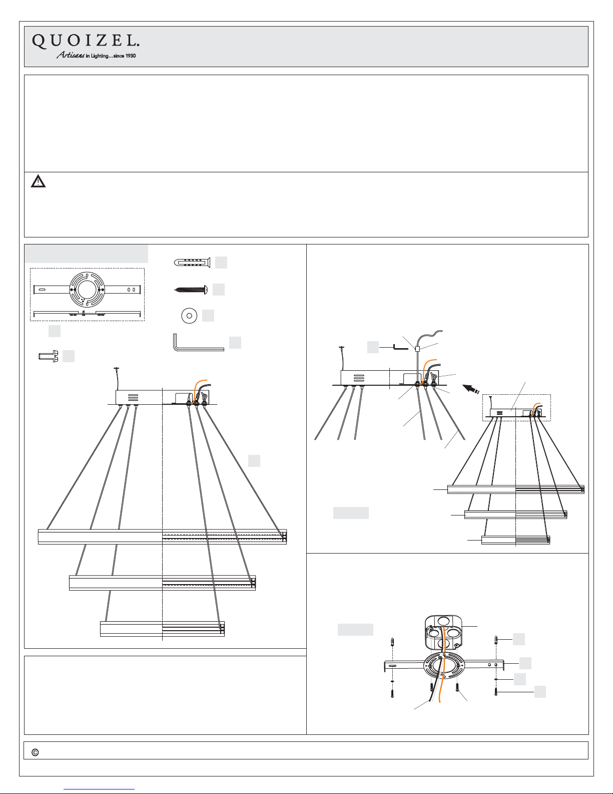
Package Contents
2.4mm
13Ga13Ga
G
ND
Crossbarx1Assembly
A
Mounting Screw
B
x2
E
C
D
Washer
x2
Wall Anchor
x2
Screw
x2
Allen Wrench
F
x1
(Step 1 Continued)
B. Move the safety clip on the cable until there is enough distance for
cable adjustment. Push pin underside of the ceiling canopy and
adjust the cable in or out of the ceiling canopy to achieve your
desired hanging height. Carefully tuck all slack wires inside of the
ceiling canopy.
C. Make sure each ring is horizontal after adjustments.
Set Screw
F
Cord Clasp
Safety Clip
Ceiling
Canopy
Pin
Hex Nut
Fixture
Body
G
x1
STEP 1 Adjust the Fixture Body Height-
A. By using the Allen Wrench (F), unscrew the set screw on the cord
clasp. Push the pin on the bottom of the ceiling canopy and adjust
the cord to your desired hanging height. Release your hand on the
pin and move the cord clasp to the hex nut inside of the ceiling
canopy. Tight the set screw on the cord clasp until snug to engage
the cord.
Cord
Cable
Top Ring
Figure 1
Medium Ring
Bottom Ring
STEP 2 Attach Crossbar Assembly to Outlet Box-
A. Attach the Crossbar Assembly (A) onto the outlet box and make two
marks on the ceiling from keyholes.
B. Remove the Crossbar Assembly (A). Using a 1/4” drill bit, drill holes
at each (2) locations marked on the ceiling.
Figure 2
Outlet Box
C
A
E
D
Supply Wires with
Ground Wire
Outlet Box Screw
(not included)
2018 QuoizelInc.
visit us on-line atwww.quoizel.com
1of2
ReleasedDate:2018-04-13
Page 2
(Step 2 Continued)
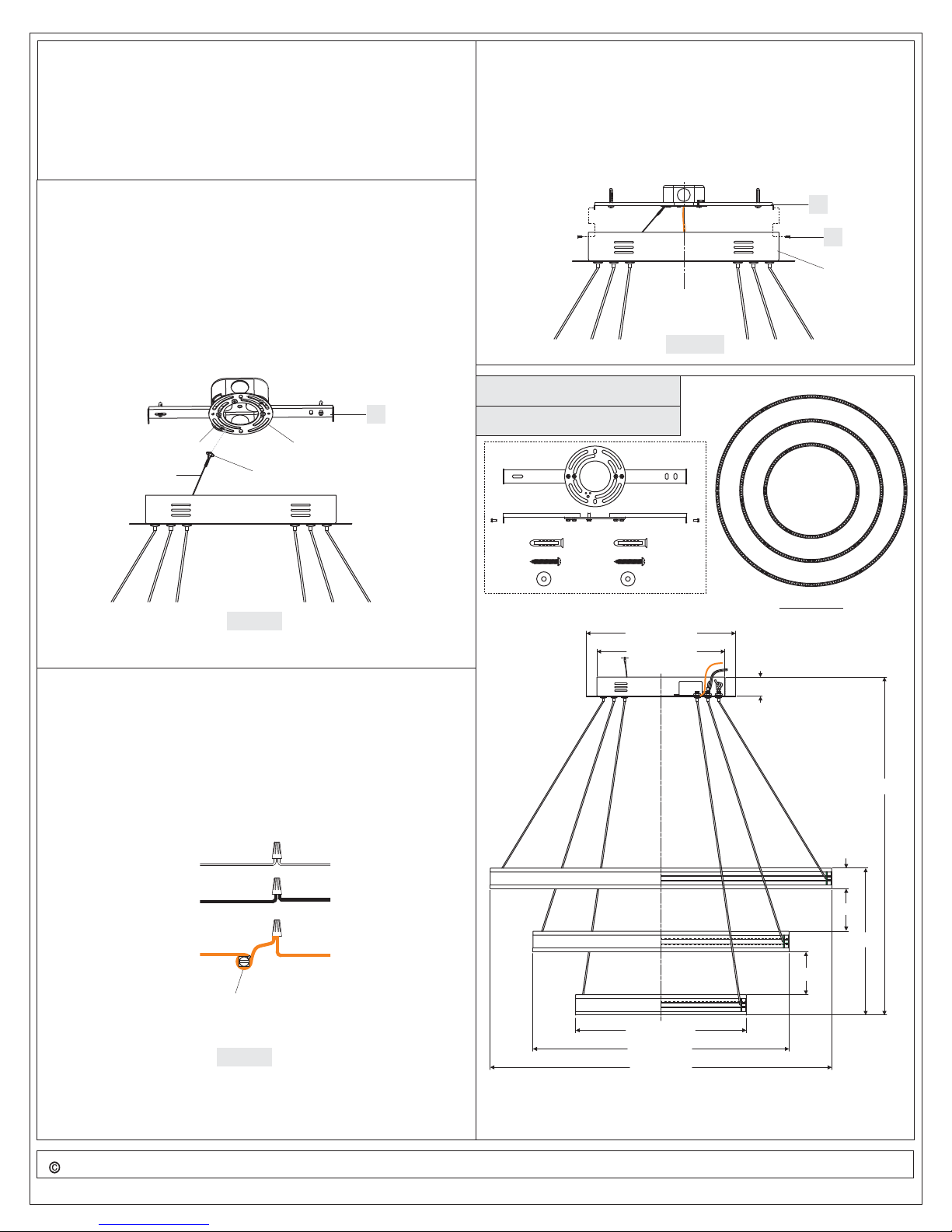
STEP 5 - Attach Fixture Body to Crossbar
C. Insert Wall Anchors (C) into drilled holes completely.
D. Pass supply wires and ground wire through the center hole of the
Crossbar Assembly (A).Attach the Crossbar Assembly (A) to outlet
box. Thread outlet box screws (not included) into mounting holes on
the outlet box. Pass Washers (E) over Screws (D) and thread
Screws (D) into Wall Anchors (C). Hand tighten until snug with
screwdrivers.
STEP 3 - Attach the Lanyard
A. The purpose of the lanyard is to provide a means to support the
fixture hands free from the junction box while connecting the
electrical wires.
B. Turn the Button Stop so it may be inserted into a Crossbar slot. Make
sure the Button Stop is completely inside the Crossbar. Slowly
release the fixture to make sure it is supported by the Button Stop.
Proceed to the wiring steps in the next step. Once you are complete
with the wiring, the Lanyard will push into the junction box when the
fixture is placed for final mounting.
A
Slot
Lanyard
Crossbar Assembly
Button Stop
A. Fit excess cord and electrical wires in the ceiling canopy properly.
Line up the holes on the side of the ceiling canopy to the mounting
holes on the Crossbar Assembly (A). Secure them with Mounting
Screws (B). Tighten until sung.
Your fixture is now assembled and ready to use. Enjoy!
A
B
Ceiling
Canopy
Figure 5
PCCA2831EK
FINISH: EARTH BLACK
2.4mm
13Ga13Ga
GN
D
Figure 3
STEP 4 - Wire Connections
A. Wrap bare or green ground wire around green ground screw on the
crossbar, no less than 2 inches from the end of the wire. Tighten the
green ground screw.
B. Use standard wire connectors (not included) to make all wire
connections. Twist connectors until wires are tightly joined together.
Wrap each connection with approved electrical tape and carefully
stuff all the connected wires into the Outlet Box.
White wire
from outlet box
Black wire from
outlet box (or Red)
Bare, or Green
Ground wire
from outlet box
White wire
from fixture
Black wire
from fixture
Ground wire
from Fixture
Green Ground Screw
on the Crossbar
Figure 4
TOP VIEW
13.75” Dia.
11.75” Dia.
1.75”
100”
2”
4”
14”
4”
15.75” Dia.
23.5” Dia.
31.5” Dia.
2018 QuoizelInc.
NOTE: ALL DIMENSIONS ARE ROUNDED
UP TO THE NEAREST 1/4"
visit us on-line atwww.quoizel.com
2of2
ReleasedDate:2018-04-13
 Loading...