

ASSEMBLY / INSTALLATION INSTRUCTIONS
6 CORPORATE PARKWAY
GOOSE CREEK SC 29445
www quoizel com
..
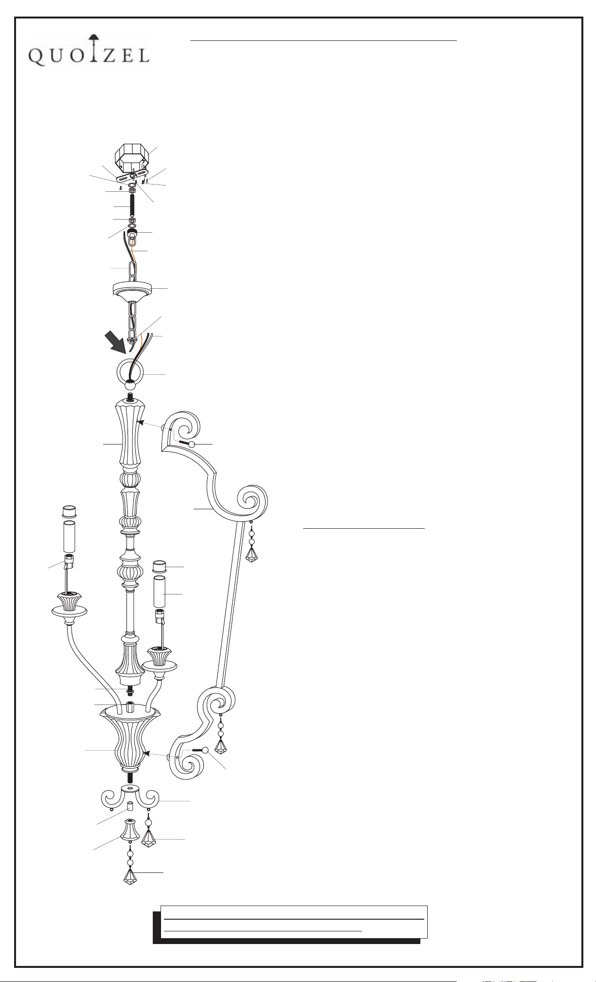
CROSSBAR
SHAKE PROOF
WASHER A
LOCK NUT A
LOCK NUT B
SHAKE PROOF
WASHER B
FIXTURE CHAIN
CENTER COLUMN
SOCKET
NIPPLE with
HEX NUT
HEX COUPLING
JUNCTION BOX
SPACER TUBE
FINIAL
NIPPLE
,.
OUTLET BOX
HOUSE SUPPLY and
GROUND WIRES
OUTLET BOX SCREWS
not supplied()
GREEN GROUND SCREW
CANOPY CHAIN LOOP
FIXTURE SUPPLY
and GROUND WIRE
CEILING CANOPY
CANOPY LOCK RING
FIXTURE SUPPLY
and GROUND WIRE
FIXTURE LOOP
LOCK SCREW
SIDE ARM
CAP
CANDLE
COVER
LOCK SCREW
SCROLL PART
CRYSTAL
1 Before beginning the installation carefully unpack
.
and identify all parts referring to the illustration
2 Turn power to the installation point OFF at circuit
.
breaker
3 Locate NIPPLE with HEX NUT. Thread end of NIPPLE
.
.
,.
,
into HEX COUPLING. Using pliers, thread the HEX NUT
against HEX COUPLING and hand tighten until snug.
Slip down the CENTER COLUMN and thread FIXTURE
LOOP onto the nipple to secure it. Hand tighten until snug.
4. Locate SCROLL PART and SPACER TUBE over end of
NIPPLE on the bottom center of JUNCTION BOX. Secure
them by threading FINIAL onto the NIPPLE. Hand tighten
until snug.
5. Locate SIDE ARM. Match the holes on SIDE ARM with
mounting holes on the side of CENTER COLUMN and
JUNCTION BOX. Thread LOCK SCREWS into mounting
holes to secure them. Hand tighten until snug.
6. Locate CRYSTALS onto the hangers on SCROLL PART,
FINIAL and SIDE ARMS. There are 2 kinds of CRYSTALS.
Please refer to the illustration for identification of
locations.
7)
.(
For Canadian installations, please refer to Page 2
Fasten the CROSSBAR to the OUTLET BOX with
(2)OUTLET BOX SCREWS(not supplied). Proceed to
thread LOCK NUT A and SHAKE PROOF WASHER A
onto the top end of NIPPLE. Thread NIPPLE into the
center of CROSSBAR. Locate the LOCK NUT B onto
the bottom end of the NIPPLE. Tighten LOCK NUT A
against CROSSBAR with plier until snug.
8. Locate the FIXTURE CHAIN and determine desired
hanging height of fixture. Adjust chain by removing
links if needed. Please note that depending on chain
material thickness, you might be required to use chain
pliers to spread links open. Proceed to attach one
end of chain to FIXTURE LOOP, attached to top of
fixture. Pass the fixture wires through FIXTURE
CHAIN alternating links. Proceed to pass the fixture
wires through the following mounting components in
this order: 1)CANOPY LOCK RING; 2)CEILING
CANOPY 3 CANOPY CHAIN LOOP 4 SHAKE
PROOF WASHER B and LOCK NUT B 5 NIPPLE
6 LOCK NUT A and SHAKE PROOF WASHER A
).
9. (2 people recommended for
Making the connections:
;) ;)
;) ;
the remaining steps) Position the fixture under the
ceiling mounted outlet box. Pass SHAKE PROOF
WASHER B over the NIPPLE. Thread CANOPY
CHAIN LOOP onto NIPPLE. Thread LOCK NUT B
down the NIPPLE, against the CANOPY CHAIN LOOP
and snug with pliers. Pass the wires through the
NIPPLE. Take up wire slack and trim wires so that
approx. 6” will remain inside outlet box. Proceed to
attach the top of the FIXTURE CHAIN to the bottom of
the CANOPY CHAIN LOOP. Using wire connectors
(not supplied) connect the HOUSE GROUND WIRE to
the FIXTURE GROUND WIRE connect the HOUSE
;
WHITE WIRE to the FIXTURE SUPPLY WIRE (WHITE
or RIBBED SIDE); connect the HOUSE BLACK (or
RED) WIRE to the FIXTURE SUPPLY WIRE(BLACK
or SMOOTH SIDE). Wrap each connection with
approved electrical tape.
10.With the proper connections made, proceed to push
the CEILING CANOPY upward over the OUTLET BOX.
Be sure that all wires are carefully tucked into the
OUTLET BOX cavity. Secure canopy against ceiling
by threading CANOPY LOCK RING onto the CANOPY
LOOP. Tighten until snug.
11.Position SOCKET through the CANDLE COVER and
place CAP onto the top end of CANDLE COVER. Install
bulbs referring to fixture markings and/or labels for
maximum wattage.
12. Restore power to the installation point ON. Retain this
sheet for future reference.
CRYSTAL
IF IN DOUBT ABOUT ELECTRICAL INSTALLATION,
CONSULT A LICENSED ELECTRICIAN!
IS MQ5206
-
Page1of3
2006 10-26
-
6 CORPORATE PARKWAY
GOOSE CREEK SC 29445
www quoizel com
..
,.
INSTALLATION INSTRUCTIONS:
FOR FIXTURES OVER 25 LBS. (Canada Only)
(
Please use the information outlined in this sheet for the ceiling
installation part of your fixture assembly.
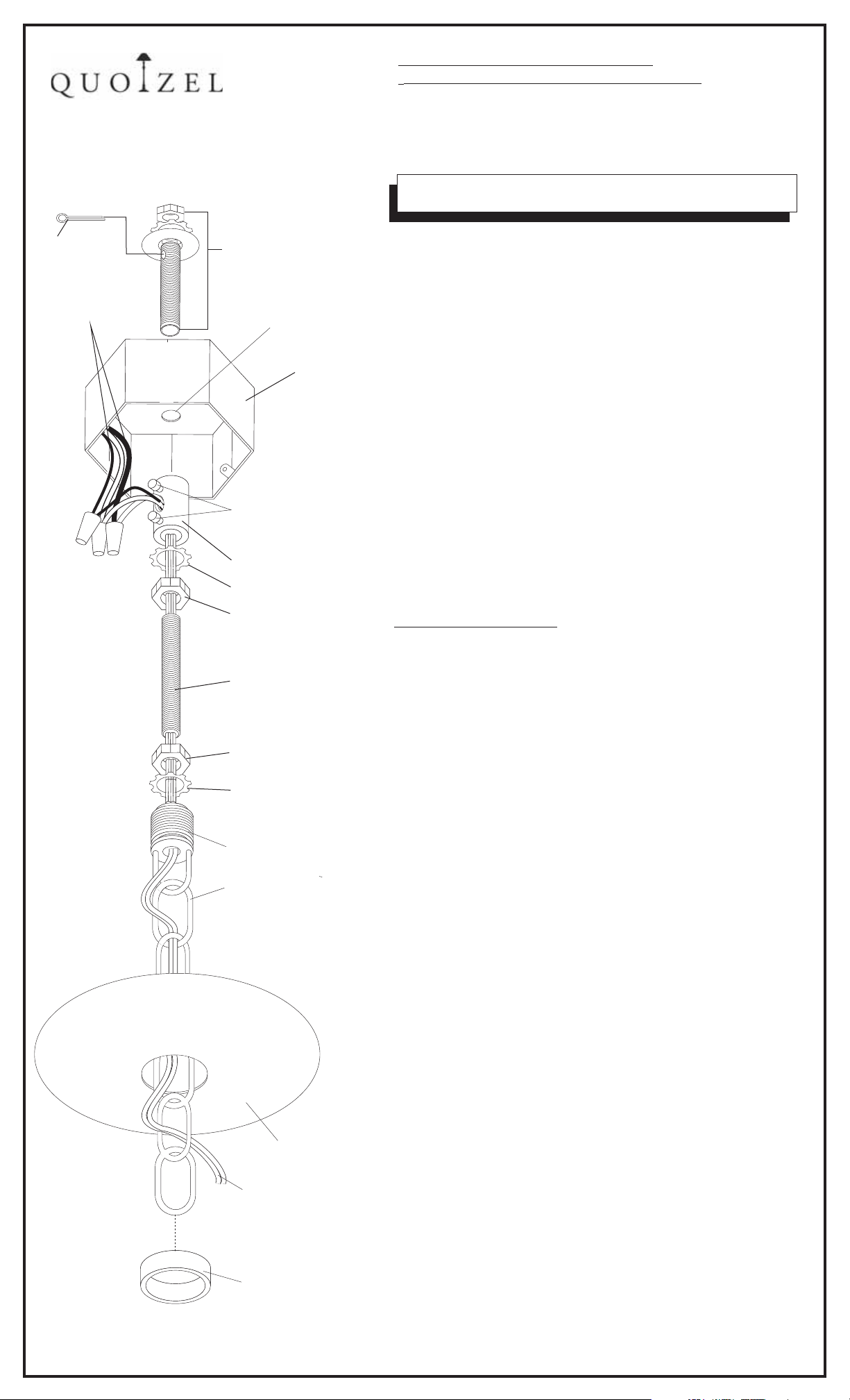
COTTER
PIN
HOUSE SUPPLY
and GROUND
WIRES
FIGURE 1.
3/8-18 NIPPLE, SHAKE
PROOF WASHER AND
HEX NUT (INCLUDED)
HOLE DRILLED
INSIDE OUTLET
BOX
OUTLEX BOX
SET SCREWS
COUPLING
SHAKE PROOF WASHER A
Quoizel recommends a licensed electrician or contractor be
consulted for this installation.
1. Before installing fixture, carefully unpack and identify all parts
referring to illustration FIGURE 1. Be sure the power to the
installation point is OFF .
2.
(Refer to Figure 2, page 3) This weight of this fixture will require
at circuit breaker
a means of support independent of the OUTLET BOX. This
fixture must b supported by 3/8-18 NPSM NIPPLE(supplied)
e
Th NIPPLE should be positioned so that 3/4“ protrudes into
e
the OUTLET BOX cavity. Note: the opposite end of the NIPPLE
must be attached to a structural or bridging member of
sufficient strength to support the fixture weight. A COTTER PIN
has been included and should be installed into the top of
NIPPLE, above HEX NUT for added safety. A clearance hole
must be drilled on the inside top center of the OUTLET BOX.
Please refer to Figure 2, page 3 for detailed illustration. We
recommend the consultation of a licensed electrician or
contractor due to the complexity of this installation.
3. With the NIPPLE properly situated, locate COUPLING and proceed
to thread onto the end of the NIPPLE protruding into the OUTLET
BOX. Thread COUPLING onto pipe until tight. Tighten the top SET
SCREW with pliers to secure COUPLING to NIPPLE.
LOCK NUT A
NIPPLE
LOCK NUT B
SHAKE PROOF WASHER B
CANOPY CHAIN LOOP
FIXTURE CHAIN
CEILING
CANOPY
FIXTURE SUPPLY
WIRE
4.
Making the connections:
the rest of this installation)
(Quoizel recommends (2) people for
Proceed to unravel the FIXTURE
SUPPLY and GROUND WIRES. Locate the FIXTURE CHAIN and
attach one end to the FIXTURE LOOP at the top of FIXTURE.
Please note that depending on chain material thickness, you might
be required to use chain pliers to spread chain links open. Proceed
to pass the FIXTURE SUPPLY and GROUND WIRES through the
chain, alternating links. Proceed the pass the wires through the
following mounting components in this order: 1) CANOPY LOCK
RING 2) CEILING CANOPY
;
Position the fixture under the OUTLET BOX. Locate the
.
CANOPY
CHAIN LOOP; SHAKE PROOF WASHER B and LOCKNUT B;
NIPPLE ; LOCK NUT A and SHAKE PROOF WASHER A. Thread
LOCK NUT A onto top end of NIPPLE. Pass SHAKE PROOF A over
top end of NIPPLE. Thread LOCK NUT B onto the end of NIPPLE.
Pass SHAKE PROOF B over end of NIPPLE. Thread the CANOPY
CHAIN LOOP onto the end of NIPPLE. Thread LOCK NUT B down
NIPPLE and snug against top of CANOPY CHAIN LOOP with pliers.
Pass wires through the bottom center CANOPY CHAIN LOOP
through NIPPLE. Pass
fixture wires through the bottom center of
the COUPLING. Pull wires through the wire way hole on side of
COUPLING.
Take up wire slack and trim wires so that approx. 6” will
remain inside outlet box.
Proceed to thread the NIPPLE into the bottom center of the
COUPLING until tight. Tighten the LOWER SET SCREW. Proceed
to thread LOCK NUT A and SHAKE PROOF WASHER A up
NIPPLE until seated against the bottom of the COUPLING.
Tighten until snug with pliers. Attach the top of the FIXTURE
CHAIN to the CANOPY CHAIN LOOP. Using wire connectors
(not supplied),
HOUSE GROUND WIRE
connect the FIXTURE GROUND WIRE to
connect the HOUSE WHITE WIRE to
;
the FIXTURE SUPPLY WIRE (WHITE or RIBBED SIDE); connect
the HOUSE BLACK (or RED)WIRE to the FIXTURE SUPPLY
WIRE (BLACK or SMOOTH SIDE). Wrap connection with
each
approved electrical tape.
5. With the proper connections made roceed to push the CEILING
p
CANOPY upward over the OUTLET BOX. Be sure that all wires are
carefully tucked into the OUTLET BOX cavity. Secure canopy
against ceiling by threading CANOPY LOCK RING onto the
CANOPY LOOP. Tighten until snug.
CHAIN
CANOPY LOCK
RING
6. Refer back to Page 1, Step 8 and finish installation.
IS MQ5206
-
Page2of3
2006 10-26
-
 Loading...