

Page 1
AssemblyInstructionSheet#IS-LLN1508PN
ForStyleLLN1508PN
Quoizel,Inc.
6CorporateParkway
GooseCreek,SC29445
CustomerService
Phone631.273.2700
Fax631.231.7102
www.quoizel.com
ToolsRequired:Flatheadscrewdriver,Phillipsscrewdriver,pliers,wirecutters,wirestrippers,electricaltape,
safetyglasses.
BulbRecommended:
EstimatedAssemblyTime:
Preparation:
belowtobesureallpartsarepresent.Ifanypartsaremissingordamaged,donotattempttoassemble,install,or
operatethefixture.Contactcustomerserviceforreplacementparts.
Identifyandinspectallpartsbeforebeginninginstallation.Checkpackagecontentlistanddiagrams
(1)MediumBase100WbulbMaximum,Alternatebulb(1)23WCFLMaximum.
20-30minutes
WarningsandCautions
Turnoffelectricityatcircuitbreakerormainfuseboxbeforeinstallation.Consultalicensedelectricianifindoubt.
Theseinstructionsareprovidedforyoursafety.Itisveryimportantyoureadthemcompletelybeforeinstallingthefixture.Westrongly
recommendthatalicensed,professionalelectricianperformtheinstallation.
Disconnectfixturefrompowersourcebeforereplacingbulbs.Makesurebulbsaregivensufficienttimetocoolbeforeremoval.Donotsubject
glasspartstoanyshockwhileinoperationorshatteringmayresult.
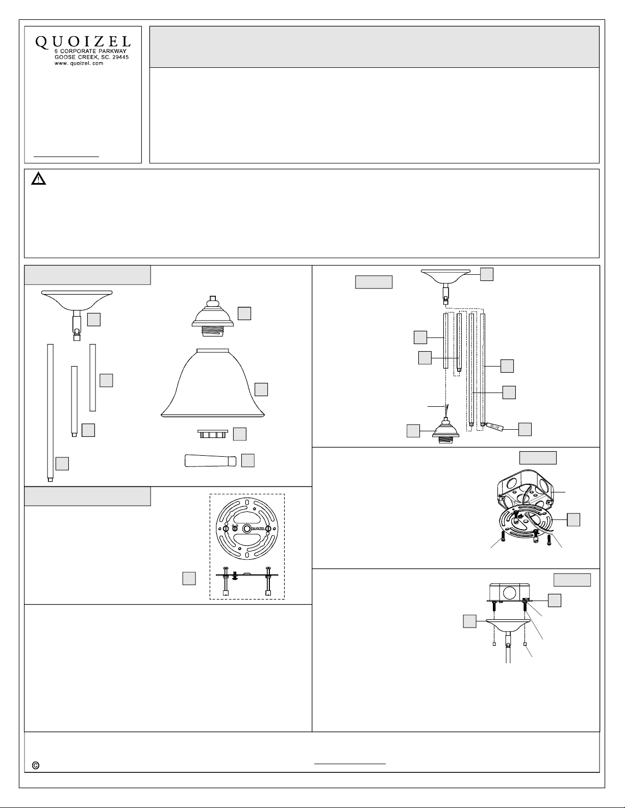
PackageContents
Socket
Assembly
E
x1
F
SocketCollar
G
x1
Glue
H
x1
Shade
x1
D
A
C
12” Rod
x2
Ceiling
Canopy
x1
6” Rod
B
x1
6”Rod
withNipple
x1
GLUE
HardwareContents
CrossbarAssembly
STEP1AssembletheRodsandtheCeilingCanopy-
A.DeterminetheRods(B/C/D)tobeassembledtotheSocket
Assembly(E)accordingtoyourhangingheight.
B.Passthesupplywiresandgroundwirethroughthechosenrods
(B/C/D)andtheCeilingCanopy(A).ThreadtheSocketAssembly
(E),thechosenRods(B/C/D)andtheCeilingCanopy(A)together.
Handtightenuntilsnug.
Note:Ifnecessary,adherethesuppliedGlue(H)tothenippleonthe
endoftheRods(C/D)beforeyoutightentherods(B/C/D)andthe
SocketAssembly(E)together.
Needassistancewithpartsorassembly?CallQuoizelcustomerserviceat1-631-273-2700
2014QuoizelInc.
x1
AA
ThankyouforpurchasingaQuoizelproduct.
orvisituson-lineatwww.quoizel.com
Figure1
B
C
SupplyWires
andGroundWire
E
STEP2InstallCrossbarAssembly-
A.Passthesupplywiresthroughthe
CrossbarAssembly(AA).Attachthe
CrossbarAssembly(AA)totheOutlet
BoxwiththeheadoftheGreen
GroundScrewfacingyou.Secureit
withOutletBoxScrews(notincluded).
Tightenuntilsnug.
OutletBoxScrews
(notincluded)
STEP3FitCeilingCanopyto
A.
not,adjustthelengthofthenippleontheCrossbarAssembly(AA)by
1of2
-
CrossbarAssembly
Removemountingballsfromthe
CrossbarAssembly(AA).Fitthe
CeilingCanopyAtothe
CrossbarAssembly(AA)and
securewithmountingballs.
Note:The()
shouldbesnugagainstthe
ceiling
andthemountingballs.If
unscrewingthepreassembledhexnutandlockwasherandthen
screwingthemountingscrewsinoroutofthecrossbaruntilthe
correctlengthisachieved.Oncethe()issecure,
removethemountingballand()andproceedto
Step4.
()
CeilingCanopyA
CeilingCanopyA
A
D
D
H
Figure2
withGroundWire
A
MountingBall
CeilingCanopyA
Outlet
Box
AA
SupplyWires
Figure3
AA
HexNutand
LockWasher
MountingScrew
March2014
Page 2
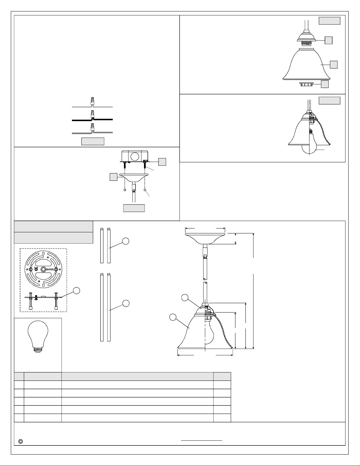
STEP4-WireConnections
A.Usestandardwireconnectors(notincluded)tomakeallwire
connections.(Connectorsarenotincludedwithfixture.)Stripand
preparewireendsaccordingtoinstructionssuppliedwith
connectors.
B.ConnectWhiteSupplyWirefromtheOutletBoxtoRibbedsideWire
fromfixture.
C.ConnectBlack(orRed)SupplyWirefromtheOutletBoxtoSmooth
sideWirefromfixture.
D.ConnectGroundWirefromtheOutletBoxtoGroundWirefrom
fixture.
E.Twistconnectorsuntilwiresaretightlyjoinedtogether.
F.Wrapeachconnectionwithapprovedelectricaltapeandcarefully
stuffalltheconnectedwiresintotheOutletBox.
Whitewire
fromsupply
Blackwirefrom
supply(orRed)
Groundwire
fromsupply
Figure4
STEP5InstallFixtureBody-
A.Carefullytuckallwiresintotheoutlet
boxandpositiontheCeilingCanopy
(A)overtheoutletbox.Alignthe
holesintheCeilingCanopy(A)with
themountingscrews,thenattachthe
CeilingCanopy(A)usingthe
previouslyremovedmountingballs.
Handtightenuntilsnug.
Ribbedsidewire
fromfixture
Smoothsidewire
fromfixture
Groundwire
fromfixture
A
Figure5
AA
Mounting
Screw
MountingBall
STEP6InstallShade-
A.PlacethetheShade(F)overtheSocketand
securewiththeSocketCollar(H).Hand
tightenuntilsnug.
STEP7InstallBulb-
A.Thisfixtureusesstandardbulbwith
mediumbase.Maximum100watts.
B.Insertbulbandscrewsnuglyintoplace.
Yourfixtureisnowassembledandready
touse.Enjoy!
Figure6
E
F
G
Figure7
Bulb
LLN1508PN
FINISH:PALLADIANBRONZE
3
(1)100W
(NotSupplied)
NO.
1
2
3 9535KIT MOUNTINGHARDWARE&CANOPY 1
3 9012EXPN RODEXTENSIONPALLADIANBRONZE12"LX0.5"D 2
3
Medium
Bulb
Base
PARTNUMBER
G3277SH
11508PNLLN
9006EXPN ROD6”LX0.5"DEXTENSIONPALLADIANBRONZE 2
NOTE:ALLDIMENSIONSAREROUNDEDUPTOTHENEAREST1/2"
REPLACEMENTPARTDESCRIPTION
AMBERVETROGLASS
BASEPALLADIANBRONZELLN1508PN
5
4
1
5.5"Dia.
2
7.5"Dia.
1.5"
45.5"
OVERALLHEIGHTINCLUDES
(2)6"AND12"RODS
6"
5"
REQ.
1
1
2014QuoizelInc.
Needassistancewithpartsorassembly?CallQuoizelcustomerserviceat1-631-273-2700
ThankyouforpurchasingaQuoizelproduct.
orvisituson-lineatwww.quoizel.com
2of2
March2014
 Loading...