

Page 1
6 CORPORATE PARKWAY
GOOSE CREEK SC 29445
www quoizel com
..
,.
INSTRUCTION SHEET IS-KY5009
STYLE NUMBER: KY5009IB
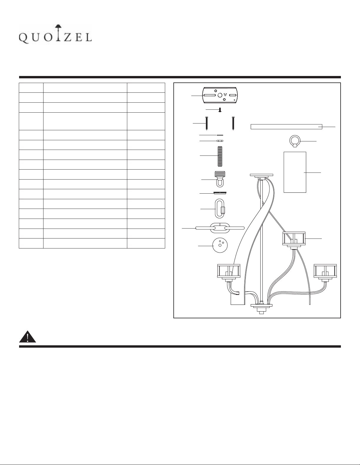
PACKAGE CONTENTS
PART
A Crossbar
B
C
D
E
F
G
H
I
J
K
L
M
N
O
DESCRIPTION
Green Ground Screw
Mounting Screw
(Independent Mounting)
Lock Washer
Hex Nut (1/4 IPS Nipple)
Nipple (1/4 IPS)
Canopy Chain Loop
Canopy Lock Ring
Quick Link
Fixture Chain
Tuck Washer
Ceiling Canopy
Fixture Loop
Shade
Fixture Assembly
QUANTITY
1pc
1pc
2pcs
2pcs
2pcs
1pc
1pc
1pc
2pcs
1pc
1pc
1pc
1pc
9pcs
1pc
ISSUED 03-2010 REVISED 2010-03-25
A
B
C
D
E
F
G
H
I
J
K
GND
R
L
M
N
O
WARNINGS AND CAUTIONS
WARNING:
● Before beginning the installation, turn off electricity at the circuit breaker box or the main fuse box by switching
off the circuit breaker or removing the fuse.
CAUTION:
● These instructions are provided for your safety. It is very important that they are read completely before the
installation of your fixture. We strongly recommend that a professional electrician install the fixture.
● Disconnect fixture from the power source before replacing the bulb(s), making sure that bulb9s) had sufficient
time to cool down. DO NOT subject the lamp to any shock while lit as shattering of lamp may result.
1OF5
Page 2
PREPARATION
STYLE NUMBER: KY5009IB
● Before beginning installation of product, make sure all parts are present. Compare parts with package contents
list and diagram above. If any part is missing or damaged, do not attempt to assemble, install or operate the
product. Contact customer service for replacement part.
● Estimated Assembly Time: 30 - 45 minutes
● Tool Required for Assembly (not included): Flathead screwdriver, Phillips screwdriver, Pliers, Electrical tape,
Wire cutter, Safety glasses and (9) 100W A19 medium base bulbs
.
● Helpful Tools (not included): Wire strippers.
INSTALLATION INSTRUCTIONS
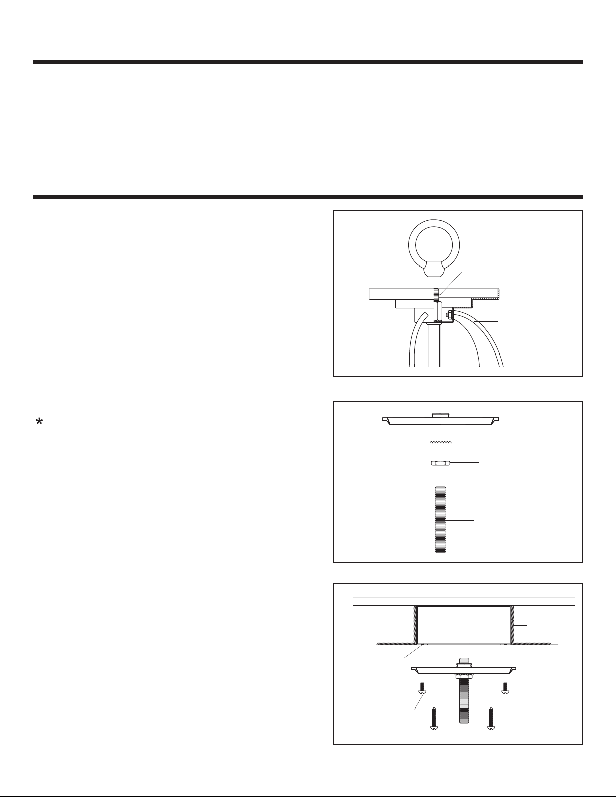
STEP 1:
a. Thread the Fixture Loop onto the Nipple in the top
center of the Fixture Assembly. Hand-tighten until
snug.
Fixture Loop
Nipple
Fixture Assembly
STEP 2:
Pliers is required on this step.
a. Thread one Hex Nut (1/4 IPS Nipple) onto top end of
the Nipple.
b. Place one Lock Washer over the top end of the Nipple
and then thread the Nipple into the center hole of the
Crossbar. Hand-tighten until snug.
c. Using pliers, thread the Hex Nut (1/4 IPS Nipple)
against the Crossbar and hand-tighten until snug.
STEP 3:
a. Drill a 5/8” diameter clearance hole on the top inside
center of the Outlet Box and through the Structural
Support Member.
b. Place Crossbar onto the Outlet Box and line up
Mounting Holes with a set of holes on Crossbar.
c. Thread Outlet Box Screws into the Mounting Holes on
the Outlet Box and tighten until snug to secure the
Crossbar.
d. Using portable screwdriver, thread Mounting Screws
into the Structural or Bridging Member and tighten until
snug.
Structural or
Bridging Member
Mounting Hole
Outlet Box Screw
not supplied()
Crossbar
Lock Washer
Hex Nut (1/4 IPS Nipple)
1 4 IPS Nipple/
Outlet Box
Crossbar
Mounting
Screw
2OF5
Page 3

INSTALLATION INSTRUCTIONS
STYLE NUMBER: KY5009IB
STEP 4:
a. Locate the Fixture Chain and attach one end of it to the
Fixture Loop at the top of the Fixture with a Quick Link
Connector.
Fixture Chain
b. Decide the length of the chain needed for your
application. You will be required to remove excess links
with bolt cutters.
Fixture Loop
Quick Link
STEP 5:
a. Unravel the Fixture Wires, Ground Wires and Safety Cable.
b. Pass the wires through alternating links on the chain. Proceed to pass the wires through the following
mounting components in this turn:
Canopy Lock Ring, Ceiling Canopy, Canopy Chain Loop, Lock Washer and Hex Nut, Nipple and Crossbar.
STEP 6:
a. Work the Safety Cable end through the Fixture Chain,
alternating every other link. Proceed to pass the Safety
Cable end through the Nipple, Crossbar and Outlet
Box. Make up the Tuck Washer Knot, refer to STEP 7.
Pull all of excess cable through all of the holes until the
Tuck Washer is very close to the opening at the end of
the 3/8-18 Pipe. Remove as much slack as possible out
of the Tuck Washer. About ½”of slack between Tuck
Washer and the hole is acceptable.
STEP 7:
a. Pull all of the Safety Cable up through the Center Hole.
b. Push the Cable down through the 12 O’clock Hole.
Leaving ½”of slack.
c. Push the Cable up through the 1 O’clock Hole and tuck
it under the cable between the Center Hole and the 12
O’clock Hole.
Safety Cable
Tuck Washer
Safety
Cable
Center Hole
12 O clock
'
Hole
Structureal or
Bridging Member
1 O clock Hole'
12
1
Outlet Box
Tuck Washer
3OF5
Page 4

INSTALLATION INSTRUCTIONS
STEP 8:
a. Thread Hex Nut (1/4 IPS Nipple) onto the end of the
Nipple and then place Lock Washer over the end of the
Nipple. Thread the Canopy Chain Loop onto the end of
the Nipple.
b. Using Pliers, thread the Hex Nut (1/4 IPS Nipple)
against the Canopy Chain Loop and tighten until snug.
c. Attach the top end of the Fixture Chain onto Canopy
Chain Loop by using Quick Link.
d. Refer to STEP 9 - Wire Connections to connect wires.
e. Push the Ceiling Canopy upward over the Outlet Box.
f. Thread the Canopy Lock Ring onto the Canopy Chain
Loop and tighten until snug to secure the Ceiling
Canopy.
Hex Nut
(1/4 IPS Nipple)
Canopy
Chain Loop
Fixture Chain
STYLE NUMBER: KY5009IB
Nipple
Lock Washer
Quick Link
Ceiling
Canopy
Canopy
Lock Ring
STEP 9:
Use Wire Connectors (not supplied) to connect the
wires.
a. Connect the House Ground Wire to the Fixture Ground
Wire.
b. Connect the House White (or Ribbed) Wire to the
Fixture Supply Wire (Black or Smooth Side).
c. Connect the House Black (or Red) Wire to the Fixture
Supply Wire (Black or Smooth Side).
d. Wrap each connection with approved electrical tape
and carefully stuff all of the connected wires into the
Outlet Box.
WHITE OR RIBBED
FROM HOUSE
BLACK (OR RED) WIRE
FROM HOUSE
GROUND WIRE
FROM HOUSE
WHITE OR RIBBED
FROM FIXTURE
BLACK OR SMOOTH
FROM FIXTURE
GROUND WIRE
FROM FIXTURE
4OF5
Page 5

INSTALLATION INSTRUCTIONS
STEP 10:
a. Place the Shade inside of the Shade Holder as shown.
STYLE NUMBER: KY5009IB
Shade
Shade
Holder
STEP 11:
a. Install correct bulbs referring to fixture markings and/or labels for maximum wattage.
Your installation is completed now. Restore electricity. Retain this sheet for future reference.
5OF5
 Loading...