

Page 1
6 CORPORATE PARKWAY
GOOSE CREEK SC 29445
www quoizel com
. .
, .
INSTRUCTION SHEET IS KD2824-
STYLE NUMBER KD2824MM:
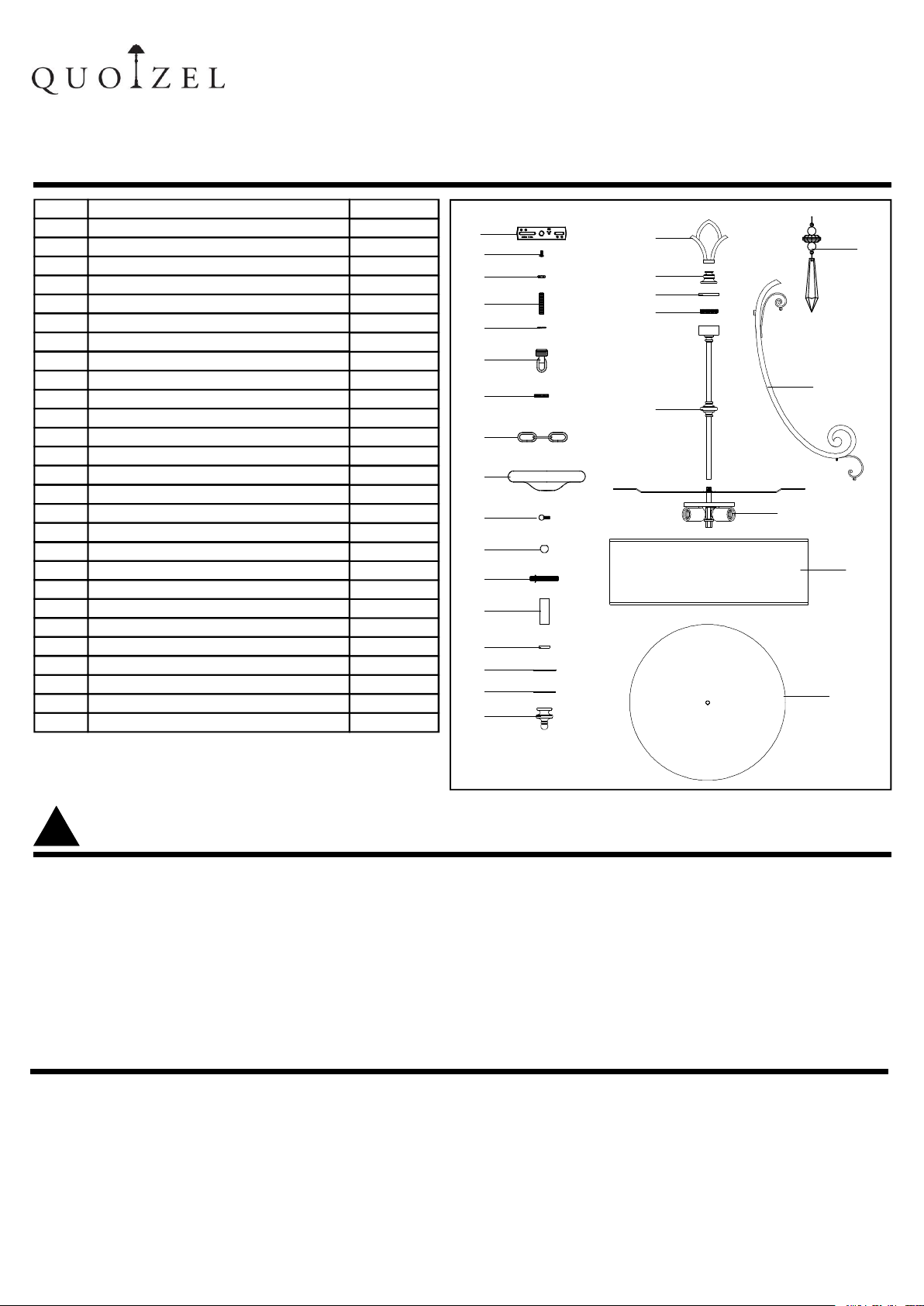
PACKAGECONTENTS
Part
A
B
C
D
E
F
G
H
I
J
K
L
M
N
O
P
Q
R
S
T
U
V
W
X
Y
Z
AA
Description
Crossbar
Green Ground Screw
Hex Nut
Nipple
Lock Washer
Canopy Chain Loop
Canopy Lock Ring
Fixture Chain
Ceiling Canopy
Lock Screw
Lock Ball
Nipple with Hex Nut
Spacer Tube
Check Ring
Flat Washer
Rubber Washer
Finial
Fixture Loop
Support Part
Cover
Nipple
Center Column
Crystal
Side Arm
Socket Assembly
Shade
Diffuser
Quantity
1pc
1pc
3pcs
1pc
2pcs
1pc
1pc
1pc
1pc
5pcs
3pcs
1pc
1pc
1pc
2pcs
2pcs
1pc
1pc
1pc
1pc
1pc
1pc
6pcs
3pcs
1pc
1pc
1pc
ISSUED 07-2008
A
B
C
D
E
F
G
H
I
J
K
L
M
N
O
P
Q
R
S
T
U
V
Revised2008-09-02
W
X
Y
Z
AA
!
WARNINGSANDCAUTIONS
WARNING:
● Before beginning the instal lation, turn off electricity at the circuit breaker box or the main fuse box by
switching off the circuit breaker or removing the fuse.
CAUTIONS:
● These instructions are provided for your safety. It is very i mpo rtant that they are read completely b efo re the
installation of your fixture. We strongly recommend that a professional electrician install the fixture.
● Disconnect fixture from the pow er source before replacing the bulb(s), making sure t he bulb(s) had suffi cient
time to cool down. DO NOT subject the lamp to any shock while lit as shattering of lamp may result.
PREPARATION
● Before beginning installation of product, make sure all parts are present. Compar e parts with pac kage
contents list and diagram above. If any part is missing or damaged, do not attempt to assemble, install or
operate the product. Contact customer service for replacement part.
● Est imated Assembly Time: 30 45 minutes
● Tool s Required for Assembly (not include d): Flathea d s crewdriver Phill ips screwdriver, pliers, ele ctrical
tape, wire cutters, safety glasses &4, 60 Watt, Type-A Medium Base Bulbs.
● Helpful Tools (not included) : Wire Stripp ers.
,
1 OF 5
Page 2
INSTALLATION INSTRUCTIONS
STYLE NUMBER KD2824MM:
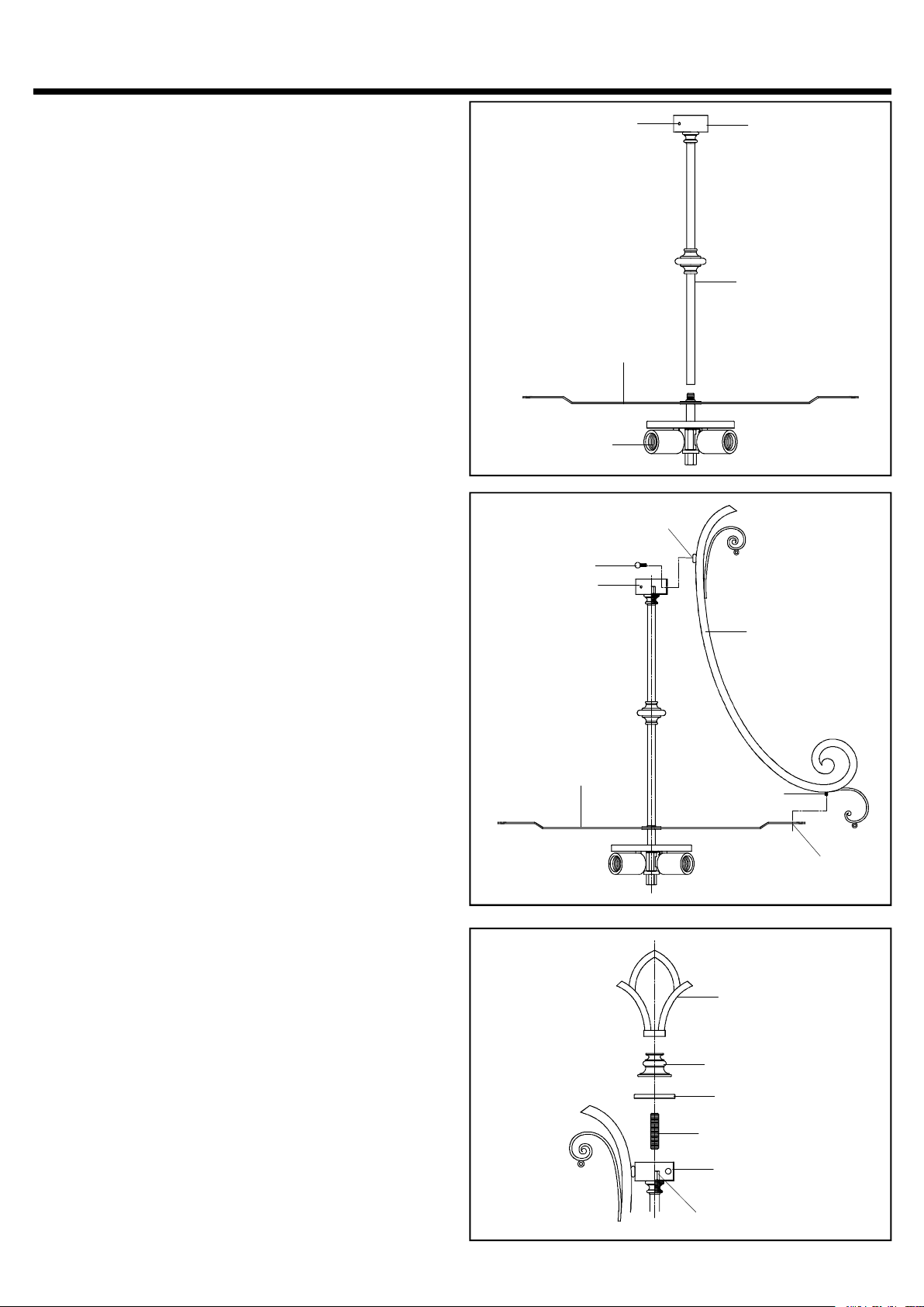
STEP 1:
a Thread the end of the Center Column onto the
.
Nipple on the top center of the Socket Assembly.
Hand tighten until snug.
Please make sure the Holes on the side of the
*
Fixture Body lining up the Spiders.
STEP 2:
a Locate the Side Arms. Place Bolts on the bottom
.
ends of arms through the Holes on Spiders.And
match Mounting Holes on other ends onto the
Holes on the side of the Fixture Body.
b. Thread Lock Screws into Mounting Holes on the
Side Arms and hand tighten until snug.
Socket Assembly
Mounting Hole
Lock Screw
Fixture Body
Hole
Spider
Fixture Body
Center Column
Side Arm
STEP 3:
a Thread the Nipple into the Hex Coupling in the
.
center of the Fixture Body Tighten until snug
b. Place the Cover and the Support Part over the
top end of the Nipple Secure them by threading
Fixture Loop onto the Nipple Hand tighten until
snug
.
. .
.
.
Spider
Bolt
Hole
Fixture Loop
Support Part
Cover
Nipple
Fixture Body
Hex Coupling
2 OF 5
Page 3

INSTALLATION INSTRUCTIONS
STEP 4:
a Thread Nipple with Hex Nut onto the Hex Coupling
.
underside of the Socket Cluster as shown.
b. Using plier, thread the Hex Nut against the Hex
coupling and hand tihgten until snug.
STEP 5:
a Locate Shade over Socket Cluster and make the
.
Tabs inside of the Shade over the Bolts extruding
from Spiders.
b. Thread Lock Balls onto Bolts and hand tighten until
snug to secure the Shade.
STYLE NUMBER KD2824MM:
Socket Cluster
Hex Coupling
Nipple with Hex Nut
Bolt
Side
Arm
Lock Ball
Tab
Socket Cluster
STEP 6:
a Place the following components over the Nipple
.
underside of the Socket Cluster in turn:
Spacer Tube, Check Ring, Flat Washer, Rubber
Washer, Diffuser, Rubber Washer and Flat Washer.
b. Thread the Hex Nut onto Nipple and hand tighten
until snug to secure the above parts.
c. At last thread the Finial onto the end of the Nipple
and tighten until snug.
Shade
Socket
Cluster
Nipple
Spacer Tube
Check Ring
Flat Washer
Rubber Washer
Diffuser
Rubber Washer
Flat Washer
Hex Nut
Finial
3 OF 5
Page 4

INSTALLATION INSTRUCTIONS
STEP 7:
a Place Crystals onto Hangers as shown in the
.
illustration.
STYLE NUMBER KD2824MM:
Hanger
Crystal
Hanger
Crystal
STEP 8:
.a Secure the Crossbar onto the Outlet Box with
Outlet Box Screws Tighten until snug. .
STEP 9:
*
Plier is required on this step
. .
Thread one Hex Nut onto top end of the Nipple
a
.
Place one Lock Washer over the top end of the
b
Nipple and then thread the Nipple into the
center lock hole of the Crossbar
. ,
Us plier thread the Hex Nut against the
c ing
rossbar and hand tighten until snug
c
.
Thread another Hex Nut onto the bottom end of
d
the Nipple
.
.
.
.
Crossbar
Outlet Box
Crossbar
Outlet BoxScrew
Lock Washer
Hex Nut
Nipple
4 OF 5
Hex Nut
Page 5

INSTALLATION INSTRUCTIONS
STEP 10:
a Adjust the Fixture Chain to your desired length by
.
removing the links if needed
Please note that depends on chain material
*
thickness you might be required to use chain
,
pliers to spread links open
b Pull the supply wires through the Fixture Chain
.
alternating links And then pull the wires through
.
the following components in turn
Canopy Lock Ring Ceiling Canopy Canopy
, ,
Chain Loop, Lock Washer and Nipple
c Place Lock Washer over the end of the Nipple and
.
thread the Canopy Chain Loop onto the end of the
Nipple
d Using plier thread the Hex Nut against the
. ,
.
Canopy Chain Loop and tighten until snug
e Attach one end of the Fixture Chain onto the
.
Fixture Loop and attach the another end of the
chain onto the Canopy Chain Loop
f Refer to Step 11 Wire Connections to connect
. -
wires
.
g Push the Ceiling Canopy upward over the Outlet
.
Box
.
h Thread the Canopy Lock Ring onto the Canopy
.
Chain Loop and tighten until snug to secure the
Ceiling Canopy
.
.
.
:
, .
.
STYLE NUMBER KD2824MM:
Nipple
Hex Nut
Lock Washer
Canopy Chain Loop
Ceiling Canopy
.
Fixture Chain
Canopy Lock Ring
Fixture Loop
STEP 11:
* ( )
Use Wire Connectors not supplied to connect
the wires
.
a Connect the House Ground Wire to the Fixture
Ground Wire.
.
b Connect the House White Wire to the Fixture
Supply Wire White or Ribbed Side .
. ( )
c Connect the House Black or Red Wire to the
Fixture Supply Wire Black or Smooth Side
.
d Wrap each connection with approved electrical
tape and carefully stuff all of the connected wires
into the Outlet Box
STEP 12
.
a Install correct Bulbs referring to fixture markings and/or labels for maximum wattage.
Your installation is completed now. Restore electricity. Retain this sheet for future reference.
.
( )
( ).
.
:
WHITE WIRE
FROM HOUSE
BLACK OR RED WIRE( )
FROM HOUSE
GROUND WIRE
FROM HOUSE
WHITE OR RIBBED
BLACK OR SMOOTH
FROM FIXTURE
FROM FIXTURE
GROUND WIRE
FROM FIXTURE
5 OF 5
 Loading...