

Page 1
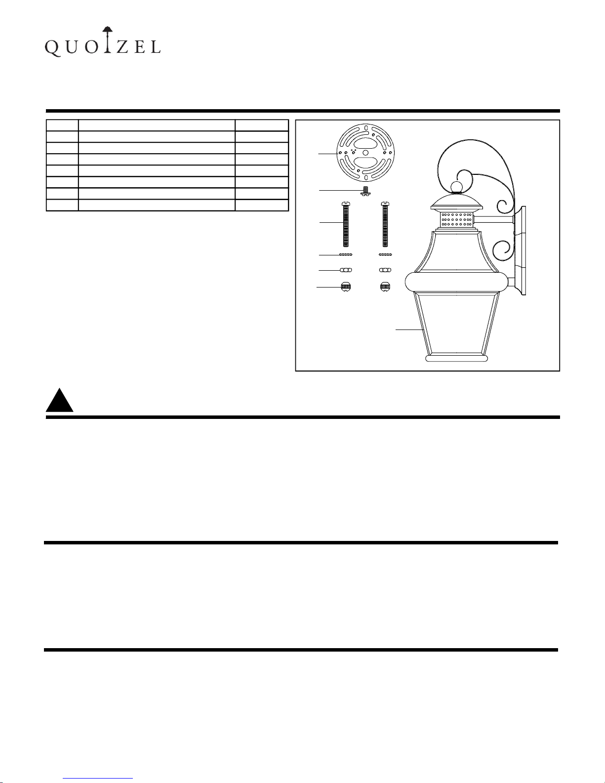
PACKAGE CONTENTS
INSTRUCTION SHEET IS 2072-
GENERAL IS SHEETS FOR OUTDOOR WALL LANTERN
ISSUED 09-2009
6 CORPORATE PARKWAY
GOOSE CREEK SC 29445
www quoizel com
, .
. .
Part
A
E
C
G
B
F
D
Description
Lock Washer
Hex Nut
Fixture Body
Crossbar
Green Ground Screw
Mounting Screw
Mounting Ball
Quantity
1pc
2pcs
2pcs
1pc
2pcs
2pcs
1pc
1 OF 3
WARNINGS AND CAUTIONS
!
PREPARATION
CAUTION
WARNING:
● Before beginning the installation, turn off electricity at the circui t breaker box or the main fuse box by
switching off the circuit breaker or removing the fuse.
CAUTIONS:
● T hese instructions are provided for your safety. It is very important that they are read completely b efore
the installation of your fixture. We strongly recommend that a professional electrician install the fixture.
● Disconnect fixture from the power source before replaci ng th e bul b( s), making sure the bulb(s) h ad
sufficient time to cool down. DO NOT subject the lamp to any shock while lit as shattering of lamp may
result.
● Before beginning installation of product, make sure all parts are present. Com pare parts with package
contents list and diagram above. If any part is missing or damaged, do not attempt to assemble, install or
operate the product. Contact customer service for replacement part.
● Estimated A ssembly Time : 15 30 minutes
● Tools Required for Assembly (not included): Flathead screwdriver Phillips screwdriver, p li er s, electrical
tape, wire cutters, safety glasses & proper Bulb(s).
● Helpful Tools (not included): Wire Strippers.
,
● T he Step 2 is only for lanyard purpose. Lanyard might be required according to the weight of the fixture.
A
B
C
D
E
F
G
Page 2
2 OF 3
INSTALLATION INSTRUCTIONS
GENERAL IS SHEETS FOR OUTDOOR WALL LANTERN
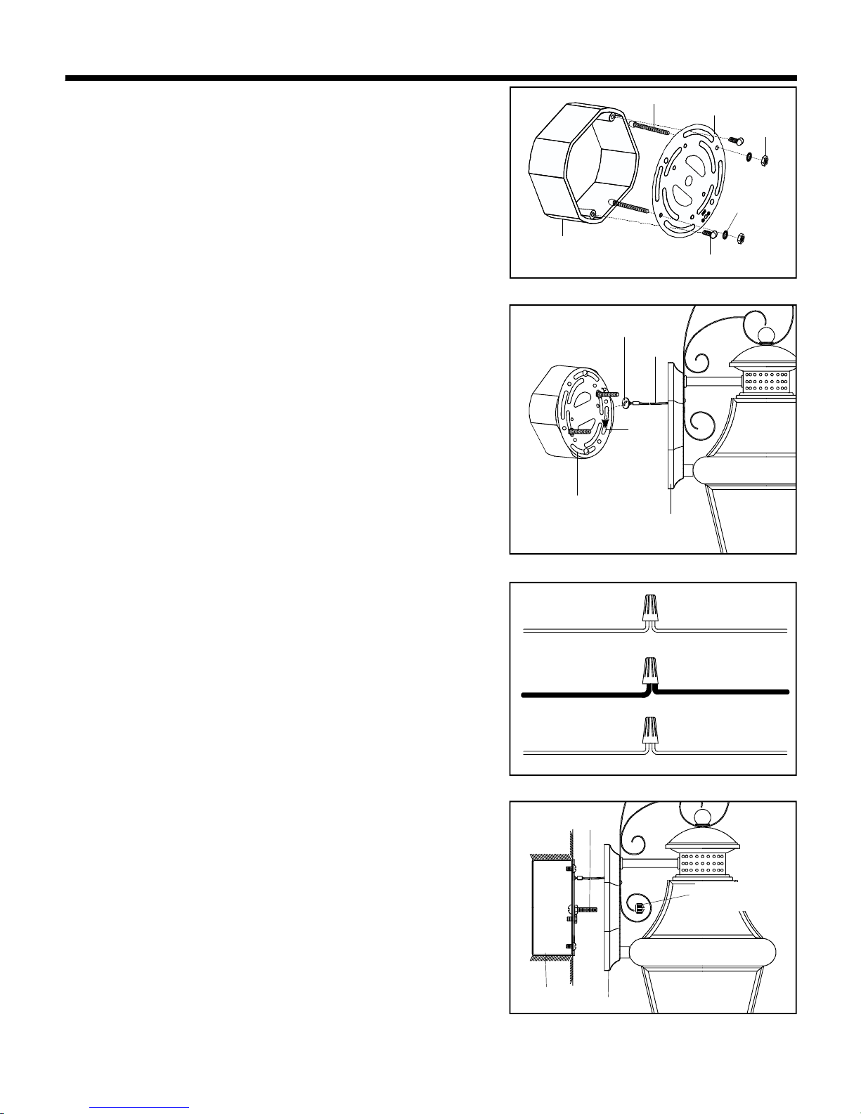
Outlet Box
Crossbar
Mounting Screw
Hex Nut
Outlet Box Screw
Lock Washer
STEP 1:
a Screw the Mounting Screws into the Crossbar place the
Lock Washers over the Mounting Screws and thread the
Hex Nuts onto the Mounting Screws as shown Secure the
position of the Mounting Screws by tightening the Hex Nuts
against the Crossbar
b Secure the Crossbar to the Outlet Box with Outlet Box
Screws
. ,
.
.
.
.
WHITE OR RIBBED
BLACK OR RED WIRE( )
FROM HOUSE
GROUND WIRE GROUND WIRE
FROM HOUSE FROM FIXTURE
WHITE OR RIBBED
FROM FIXTURE
FROM HOUSE
FROM FIXTURE
BLACK OR SMOOTH
STEP 3:
* ( )
.
.
. ( )
( )
. ( )
( ).
.
.
Use Wire Connectors not supplied to connect the
wires
a Connect the House Ground Wire to the Fixture Ground
Wire.
b Connect the House White or Ribbed Wire to the
Fixture Supply Wire White or Ribbed Side .
c Connect the House Black or Red Wire to the Fixture
Supply Wire Black or Smooth Side
d Wrap each connection with approved electrical tape and
carefully stuff all of the connected wires into the Outlet
Box
Slot
Lanyard
Backplate
Crossbar
Button Stop
STEP 2 (For Lanyard purpose only):
a Locate the Backplate onto the Crossbar and slip the Button
Stop on the end of Lanyard into the Slot on the Crossbar as
shown.
.
Mounting
Screw
Outlet Box
STEP 4:
a. Place the Backplate over the Mounting Screws and secure
with Mounting Balls. Hand tighten until snug.
Backplate
Mounting Ball
STEP 5:
a Install correct bulb(s) referring to fixture markings and or labels for maximum wattage. / .
Page 3

EXTERIOR GRADE
CAULK
OUTDOOR
FIXTURE BACKPLATE
EXTERIOR WALL SURFACE
3 OF 3
With the OUTDOOR FIXTURE properly installed in accordance with supplied Assembly/installation
instructions, proceed with caulking instructions below.
Note: Be sure EXTERIOR WALL SURFACE and FIXTURE BACKPLATE are free to dirt to caulking.
Using EXTERIOR GRADE CAULK, start on one side of FIXTURE BACKPLATE and follow contour, were
the FIXTURE BACKPLATE meets the EXTERIOR WALL SURFACE upward. Proceed to caulk over top of
backplate and down other side. to ensure proper
moisture drainage.
DO NOT CAULK BOTTOM OF FIXTURE BACKPLATE
Your installation is completed now. Restore electricity. Retain this sheet for future reference.
INSTALLATION INSTRUCTIONS
EXTERIOR GRADE
CAULK
MOUNTING BALL
STEP 6 :
a Refer to following information for caulking instructions. :
For assemble the MOUNTING BALLS please note that
you are required to apply a small amount of Silicone
sealer to the threaded side of the MOUNTING BALLS
and then install them onto the MOUNTING SCREWS
,
.
GENERAL IS SHEETS FOR OUTDOOR WALL LANTERN
 Loading...