

Quoizel GY5204K User Manual
6 CORPORATE PARKWAY
GOOSE CREEK SC 29445
www quoizel com
..
,.
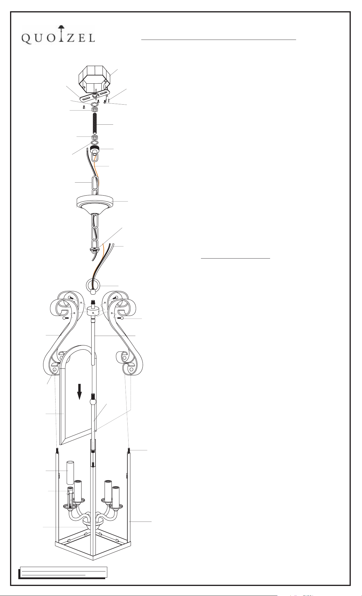
ASSEMBLY/ INSTALLATION INSTRUCTIONS
LOCK WASHER A
LOCK WASHER B
FIXTURE CHAIN
SIDE ARM
LOCK
BALL
GLASS
PAN EL
CANDLE
COVER
SOCKET
JUNCTION
BOX
CROSSBAR
LOCK NUT A
LOCK NUT B
OUTLET BOX
HOUSE SUPPLY and
GROUND WIRES
OUTLET BOX SCREWS
not supplied()
NIPPLE
CANOPY CHAIN LOOP
FIXTURE SUPPLY
and GROUND WIRE
CEILING CANOPY
CANOPY LOCK RING
FIXTURE SUPPLY
and GROUND WIRE
FIXTURE LOOP
()Large scrolled end
()Small scrolled end
CENTER
STEM
LOCK SCREW
UPPER COLUMN
SCREW
CAGE
1 Before beginning the installation carefully unpack
.
and identify all parts referring to theillustration
2 Turn power to the installation point OFF at circuit
.
breaker
3 Thread the CENTER STEM onto the coupling
.
.
,.
on the top center of the JUNCTION BOX Hand
tighten until snug Proceed to thread the CENTER
STEM UPPER COLUMN and the FIXTURE
,,
LOOP together Hand tighten until snug
.
..
,
.
4. Fasten the CROSSBARto the OUTLET BOX with
(2)OUTLET BOX SCREWS(not supplied). Proceed
to thread LOCK NUTA and LOCK WASHERA onto
the top end ofNIPPLE. Thread NIPPLE into the
center of CROSSBAR. Locatethe LOCK NUT B onto
the bottom end ofthe NIPPLE. Tighten LOCK NUTA
against CROSSBAR with plieruntil snug.
5. Locate the FIXTURECHAIN and determine desired
hanging height of fixture.Adjust chain by removing
links if needed. Pleasenote that depending on chain
material thickness, you mightbe required to use
chain pliers tospread links open. Proceed to attach
one end of chainto FIXTURE LOOP, attached to top
of fixture. Pass the fixturewires through FIXTURE
CHAIN alternating links. Proceedto pass the fixture
wires through the followingmounting components
in this order: 1)CANOPYLOCK RING; 2)CEILING
CANOPY 3 CANOPY CHAIN LOOP 4 LOCK
WASHERB and LOCK NUT B 5 NIPPLE 6 LOCK
NUT A and LOCK WASHER A
6.
Making the connections:
;) ;)
;) ; )
.
(2 people recommended forthe remaining steps)
Position the fixture underthe ceiling mounted outlet
box. Pass LOCK WASHER B overthe NIPPLE.
Thread CANOPY CHAIN LOOP ontoNIPPLE. Thread
LOCK NUT B down the NIPPLE,against the CANOPY
CHAIN LOOP and snug with pliers. Pass the wires
through the NIPPLE. Take up wire slack andtrim wires
so that approx. 6”will remain insideoutlet box.
Proceed to attach thetop of the FIXTURE CHAIN to
the bottom of the CANOPY CHAIN LOOP.
Using wire connectors (not supplied) connect the
HOUSE GROUND WIRE to theFIXTURE GROUND
WIRE connect the HOUSE WHITE WIRE to the
;
FIXTURE SUPPLY WIRE (WHITE or RIBBED SIDE);
connect the HOUSE BLACK(or RED) WIRE to the
FIXTURE SUPPLY WIRE(BLACK or SMOOTH SIDE).
Wrap each connection with approved electrical tape.
7. With the properconnections made, proceed to push
the CEILING CANOPY upward over the OUTLET
BOX. Be surethat all wires are carefully tucked into
the OUTLET BOX cavity. Secure canopy against
ceiling by threadingCANOPY LOCK RING ontothe
CANOPY LOOP. Tighten until snug.
8. Quoizel recommended 2 people for the next steps
()
Place the CAGE on a flat work surface Slip down
the GLASS PANELS inside of the CAGE Proceed
.
.
to position the SOCKET assembly into the center
of the CAGE and line up the mounting holes on
the side of the UPPER COLUMN with the SCREWS
on the four corners of the CAGE
9 Locate the SIDE ARMS Please make sure the
..
.
LARGE SCROLLED END is upside and the SMALL
SCROLLED END is downward Position the holes on
.
the bottom ends of the arms over the SCREWS on the
top end of the CAGE and match the holes on
another ends with the mounting holes on the side
of the UPPER COLUMN Secure the SIDE ARMS
with LOCK SCREWS and LOCK BALLS Hand
tighten until snug
10 Position the CANDLE COVER over the SOCKET
.
as shown Install the correct bulbs referring to the
.
.
fixture markings and or labels for maximum wattage
11 Restore power to theinstallation point ON. Retain
.
.
.
/.
this sheet for futurereference.
IF IN DOUBT ABOUT ELECTRICAL INSTALLATION,
CONSULT A LICENSED ELECTRICIAN!
Revised 2007-11 23
IS-GY5204
-
 Loading...