

Page 1

AssemblyInstructionSheet#IS-ER353BN
ForStyleER353BN
Quoizel,Inc.
6CorporateParkway
GooseCreek,SC29445
CustomerService
Phone631.273.2700
Fax631.231.7102
www.quoizel.com
ToolsRequired:Flatheadscrewdriver,Phillipsscrewdriver,pliers,wirecutters,wirestrippers,electricaltape,
safetyglasses.
BulbRecommended:
EstimatedAssemblyTime:
Preparation:
belowtobesureallpartsarepresent.Ifanypartsaremissingordamaged,donotattempttoassemble,install,or
operatethefixture.Contactcustomerserviceforreplacementparts.
Identifyandinspectallpartsbeforebeginninginstallation.Checkpackagecontentlistanddiagrams
(3)MediumBase100WbulbsMaximum,Alternatebulb(3)23WCFLMaximum.
30-45minutes
WarningsandCautions
Turnoffelectricityatcircuitbreakerormainfuseboxbeforeinstallation.Consultalicensedelectricianifindoubt.
Theseinstructionsareprovidedforyoursafety.Itisveryimportantyoureadthemcompletelybeforeinstallingthefixture.Westrongly
recommendthatalicensed,professionalelectricianperformtheinstallation.
Disconnectfixturefrompowersourcebeforereplacingbulbs.Makesurebulbsaregivensufficienttimetocoolbeforeremoval.Donotsubject
glasspartstoanyshockwhileinoperationorshatteringmayresult.
PackageContents
FixtureLoop
A
x2
6”Rod
B
x4
12” Rod
C
x4
LockScrew
O
x2
CapA
P
x2
CapB
Q
x2
UpperCollar
D
x3
E
SteelCollar
F
x3
Harpwith
SocketCollar
G
x3
Nipple
H
x3
FlatWasher
I
x3
RubberWasher
J
x3
HexNut
K
x6
SmallFlat
M
Washer
x3
Finial
N
x3
Shade
x3
L
Diffuser
x3
HardwareContents
Ceiling
BB
Canopy
x1
FixtureChain
CC
x2
Crossbar
AA
Assembly
x1
STEP1AttachCapstoSocket
A.AttachtheCaps(P/Q)totheendsofthe
STEP2AssembletheRodsandtheFixtureLoop-
A.DeterminetheRods(B/C)tobeassembledtotheSocketAssembly
B.Passthesupplywiresandgroundwirethroughthechosenrods
-
Assembly
SocketAssembly(R)andsecurewiththe
LockScrews(O).Handtightenuntilsnug.
Figure1
(R)accordingtoyourhangingheight.
(B/C)andtheFixtureLoop(A).ThreadtheSocketAssembly(R),
thechosenRods(B/C)andtheFixtureLoop(A)together.Hand
tightenuntilsnug.
Figure2
SupplyWires
andGroundWire
A
B
B
R
QuickLink
DD
x4
C
C
QPO
2014QuoizelInc.
Socket
R
Assembly
x1
ThankyouforpurchasingaQuoizelproduct.
Needassistancewithpartsorassembly?CallQuoizelcustomerserviceat1-631-273-2700
orvisituson-lineatwww.quoizel.com
1of3
R
March2014
Page 2
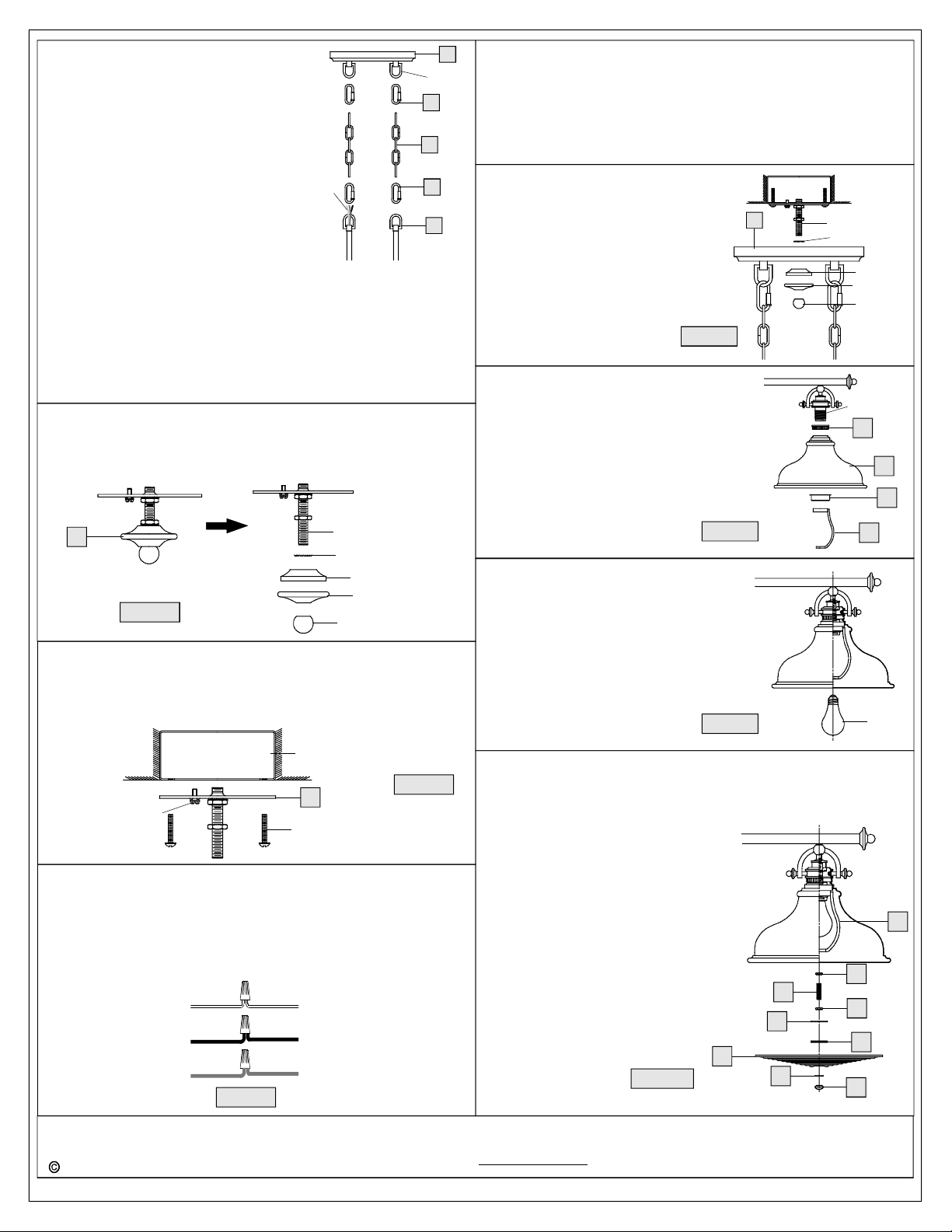
STEP3InstallFixtureChains-
A.AdjusttheFixtureChain(CC)toyour
desiredlengthbyremovingthelinksif
needed.
*
Pliersisrequiredforthisstep.
B.WiththeFixtureChain(CC)not
attachedtotheFixtureLoop(A)and
theCanopyChainLoop,pullthe
supplywiresthroughtheFixtureChain
(CC)alternatinglinks.Afterthewires
Supply
Wires
arethroughtheFixtureChain(CC),
pulltheSupplyWiresandtheGround
WirethroughtheCeilingCanopy(BB).
C.AttachoneendsoftheFixtureChains
(CC)totheFixtureLoop(A)withtwo
QuickLinks(DD)asshown.LiftthefixtureandFixtureChains(CC)
upandattachtheotherendsoftheFixtureChains(CC)ontothe
CanopyChainLoopundersideoftheCeilingCanopy(BB)withthe
resttwoQuickLinks(DD).
SuggestedrodsandchainlengthforCeilingheight:
8’ceiling:use(1)6” rodand2quicklinks
9’ ceiling:use(1)12” rod,5linksofchainand2quicklinks
10’ ceiling:use(2)12” rods,5linksofchainand2quicklinks
STEP4SeparatepartsfromCrossbarAssembly-
A.RemovetheFinial,theCovers,andtheLockWasherfromthe
CrossbarAssembly(AA).
BB
Ceiling
Loop
DD
CC
DD
A
fromfixture.
C.ConnectBlack(orRed)SupplyWirefromtheOutletBoxtoSmooth
sideWirefromfixture.
D.ConnectGroundWirefromtheOutletBoxtoGroundWirefrom
fixture.
E.Twistconnectorsuntilwiresaretightlyjoinedtogether.
F.Wrapeachconnectionwithapprovedelectricaltapeandcarefully
stuffalltheconnectedwiresintotheOutletBox.
STEP7InstallCeilingCanopy-
A.AttachtheLockWasher,theCeiling
Canopy(BB)andtheCoversoverthe
endoftheNippleasshown.Secure
bythreadingtheFinialontothe
Nipple.Handtightenuntilsnug.
BB
Nipple
LockWasher
CoverA
CoverB
Finial
Figure7
STEP8InstallShade-
A.PlacetheUpperCollar(D),theShade(E)
andtheSteelCollar(F)inturnandsecure
withtheHarpwithSocketCollar(G).Hand
Socket
D
tightenuntilsnug.
E
F
AA
Nipple
LockWasher
CoverA
CoverB
Figure4
Finial
STEP5InstallCrossbar-
A.AA)AttachtheCrossbar(totheOutletBoxwiththeheadofthe
GreenGroundScrewfacingyou.SecureitwithOutletBoxScrews
(notincluded)Tightenuntilsnug..
OutletBox
Figure5
GroundScrew
Green
AA
OutletBoxScrew
(notincluded)
STEP6-WireConnections
A.Usestandardwireconnectors(notincluded)tomakeallwire
connections.(Connectorsarenotincludedwithfixture.)Stripand
preparewireendsaccordingtoinstructionssuppliedwith
connectors.
B.ConnectWhiteSupplyWirefromtheOutletBoxtoRibbedsideWire
Whitewire
fromsupply
Blackwirefrom
supply(orRed)
Groundwire
fromsupply
Ribbedsidewire
fromfixture
Smoothsidewire
fromfixture
Groundwire
fromfixture
Figure6
Figure8
STEP9InstallBulb-
A.Thisfixtureusesstandardbulbwith
mediumbase.Maximum100watts.
B.Insertbulbandscrewsnuglyintoplace.
Figure9
STEP10InstallDiffuser-
A.ThreadoneHexNut(K)totheNipple
(H)approxhalfway.ScrewtheNipple
(H)intothebottomendoftheHarp(G)
andtightenuntilsnug.Byusingpliers,
threadtheHexNut(K)againsttheHarp
(G)andhandtightenuntilsnug.
B.ThreadanotherHexNut(K)ontothe
endoftheNipple(H)andadjustitto
properlocationforrestcomponents.
AttachtheFlatWasher(I),theRubber
Washer(J),theDiffuser(L)andthe
SmallFlatWasher(M)overtheNipple
(H)inturn.SecurethemwiththeFinial
(N)andhandtightenuntilsnug.
Yourfixtureisnowassembledandready
touse.Enjoy!
L
Figure10
I
M
G
Bulb
G
K
H
K
J
N
2014QuoizelInc.
Needassistancewithpartsorassembly?CallQuoizelcustomerserviceat1-631-273-2700
ThankyouforpurchasingaQuoizelproduct.
orvisituson-lineatwww.quoizel.com
2of3
March2014
Page 3

ER353BN
FINISH:BRUSHEDNICKEL
9”x4.5”
1”
3
4
2
(3)100W
Base
Medium
Bulbs
(NotSupplied)
PARTNUMBER
G134DI
1
2
M2127SH
9006EXBN
NOTE:ALLDIMENSIONSAREROUNDEDUPTOTHENEAREST1/2"
REPLACEMENTPARTDESCRIPTION
DIFFUSER11.5"D
METALSHADEBRUSHEDNICKEL13.5"D
RODEXTENSIONBRUSHEDNICKEL6"LX0.5"D
52.5”
REQ.NO.
439012EXBN RODEXTENSIONBRUSHEDNICKEL12”LX0.5"D 4
OVERALLHEIGHT
79”
INCLUDES12”
CHAINAND
(4)QUICKLINKS
60”
OVERALLHEIGHT
INCLUDES
(4)6” AND(4)12” RODS
23”
13.5” Dia.
1
3
3
4
2014QuoizelInc.
Needassistancewithpartsorassembly?CallQuoizelcustomerserviceat1-631-273-2700
ThankyouforpurchasingaQuoizelproduct.
orvisituson-lineatwww.quoizel.com
3of3
March2014
 Loading...