

Page 1
AssemblyInstructionSheet#IS-ER1814BN
ForStyleER1814BN
Quoizel,Inc.
6CorporateParkway
GooseCreek,SC29445
CustomerService
Phone631.273.2700
Fax631.231.7102
www.quoizel.com
ToolsRequired:Flatheadscrewdriver,Phillipsscrewdriver,pliers,wirecutters,wirestrippers,electricaltape,
safetyglasses.
BulbRecommended:
EstimatedAssemblyTime:
Preparation:
belowtobesureallpartsarepresent.Ifanypartsaremissingordamaged,donotattempttoassemble,install,or
operatethefixture.Contactcustomerserviceforreplacementparts.
Identifyandinspectallpartsbeforebeginninginstallation.Checkpackagecontentlistanddiagrams
(1)MediumBase100WbulbMaximum,Alternatebulb(1)23WCFLMaximum.
30-45minutes
WarningsandCautions
Turnoffelectricityatcircuitbreakerormainfuseboxbeforeinstallation.Consultalicensedelectricianifindoubt.
Theseinstructionsareprovidedforyoursafety.Itisveryimportantyoureadthemcompletelybeforeinstallingthefixture.Westrongly
recommendthatalicensed,professionalelectricianperformtheinstallation.
Disconnectfixturefrompowersourcebeforereplacingbulbs.Makesurebulbsaregivensufficienttimetocoolbeforeremoval.Donotsubject
glasspartstoanyshockwhileinoperationorshatteringmayresult.
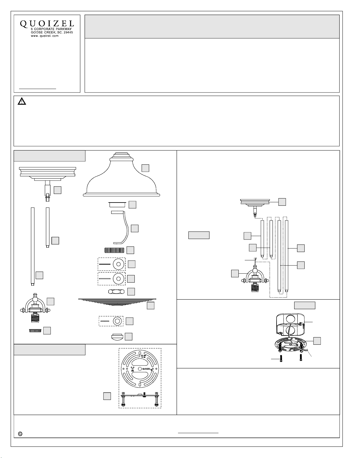
PackageContents
Ceiling
A
Canopy
x1
F
SteelCollar
G
x1
Shade
x1
STEP1AssembletheRodsandtheCeilingCanopy-
A.DeterminetheRods(B/C)tobeassembledtotheSocketAssembly
(D)accordingtoyourhangingheight.
B.Passthesupplywiresandgroundwirethroughthechosenrods
(B/C)andtheCeilingCanopy(A).ThreadtheSocketAssembly(D),
thechosenRods(B/C)andtheCeilingCanopy(A)together.Hand
tightenuntilsnug.
A
6” Rod
B
x2
12” Rod
C
x2
Socket
D
Assembly
x1
UpperCollar
E
x1
HardwareContents
CrossbarAssembly
x1
AA
Harpwith
SocketCollar
H
x1
Nipple
I
x1
FlatWasher
J
x1
RubberWasher
K
x1
HexNut
L
x2
SmallFlat
Washer
N
x1
Finial
O
x1
M
Diffuser
x1
Figure1
SupplyWires
andGroundWire
STEP2InstallCrossbarAssembly-
A.Passthesupplywiresthroughthe
CrossbarAssembly(AA).Attachthe
CrossbarAssembly(AA)totheOutlet
BoxwiththeheadoftheGreen
GroundScrewfacingyou.Secureit
withOutletBoxScrews(notincluded).
Tightenuntilsnug.
STEP3FitCeilingCanopytoCrossbarAssembly-
A.
RemovemountingballsfromtheCrossbarAssembly(AA).Fitthe
CeilingCanopyAtothe
mountingballs.Note:The()shouldbesnug
againsttheandthemountingballs.Ifnot,adjustthelengthof
thenippleontheCrossbarAssembly(AA)byunscrewingthe
preassembledhexnutandlockwasherandthenscrewingthe
()CrossbarAssembly(AA)andsecurewith
ceiling
B
B
D
OutletBoxScrews
(notincluded)
CeilingCanopyA
C
C
Figure2
Outlet
Box
AA
SupplyWires
withGroundWire
2014QuoizelInc.
Needassistancewithpartsorassembly?CallQuoizelcustomerserviceat1-631-273-2700
ThankyouforpurchasingaQuoizelproduct.
orvisituson-lineatwww.quoizel.com
1of2
March2014
Page 2
mountingscrewsinoroutofthe
crossbaruntilthecorrectlength
isachieved.OncetheCeiling
Canopy(A)issecure,removethe
mountingballandCeilingCanopy
(A)andproceedtoStep4.
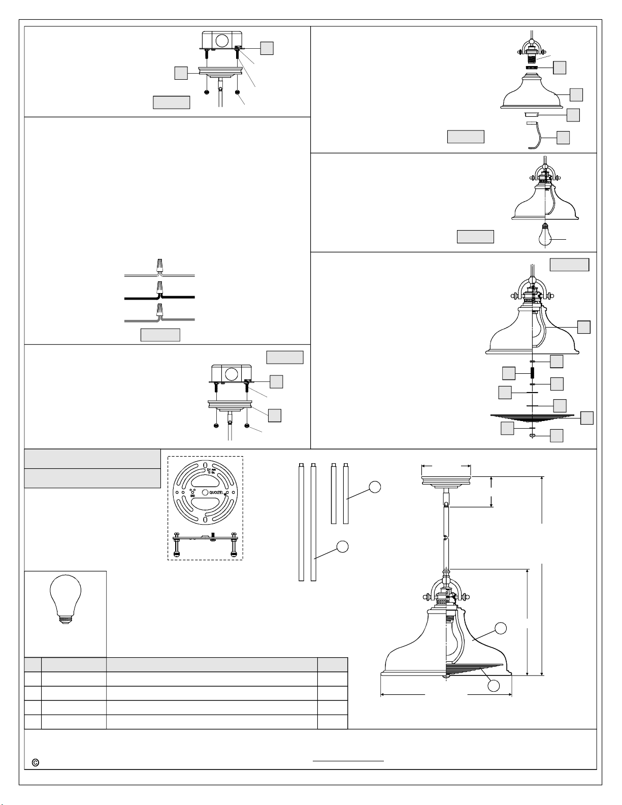
STEP4-WireConnections
A.Usestandardwireconnectors(notincluded)tomakeallwire
connections.(Connectorsarenotincludedwithfixture.)Stripand
preparewireendsaccordingtoinstructionssuppliedwith
connectors.
B.ConnectWhiteSupplyWirefromtheOutletBoxtoRibbedsideWire
fromfixture.
C.ConnectBlack(orRed)SupplyWirefromtheOutletBoxtoSmooth
sideWirefromfixture.
D.ConnectGroundWirefromtheOutletBoxtoGroundWirefrom
fixture.
E.Twistconnectorsuntilwiresaretightlyjoinedtogether.
F.Wrapeachconnectionwithapprovedelectricaltapeandcarefully
stuffalltheconnectedwiresintotheOutletBox.
Whitewire
fromsupply
Blackwirefrom
supply(orRed)
Groundwire
fromsupply
Figure4
STEP5-InstallFixtureBody
A.Carefullytuckallwiresintotheoutletbox
andpositiontheCeilingCanopy(A)over
theoutletbox.Aligntheholesinthe
CeilingCanopy(A)withthemounting
screws,thenattachtheCeilingCanopy
(A)usingthepreviouslyremoved
mountingballs.Handtightenuntilsnug.
A
Figure3
Ribbedsidewire
fromfixture
Smoothsidewire
fromfixture
Groundwire
fromfixture
AA
HexNutand
LockWasher
MountingScrew
MountingBall
Figure5
AA
Mounting
Screw
A
Mounting
Ball
STEP6InstallShade-
A.PlacetheUpperCollar(E),theShade(F)and
theSteelCollar(G)inturnandsecurewith
theHarpwithSocketCollar(H).Handtighten
untilsnug.
Figure6
STEP7InstallBulb-
A.Thisfixtureusesstandardbulbwithmedium
base.Maximum100watts.
B.Insertbulbandscrewsnuglyintoplace.
Figure7
STEP8InstallDiffuser-
A.ThreadoneHexNut(L)totheNipple(I)
approxhalfway.ScrewtheNipple(I)
intothebottomendoftheHarp(H)and
tightenuntilsnug.Byusingpliers,
threadtheHexNut(L)againsttheHarp
(H)andhandtightenuntilsnug.
B.ThreadanotherHexNut(L)ontotheend
oftheNipple(I)andadjustittoproper
locationforrestcomponents.Attachthe
FlatWasher(J),theRubberWasher(K),
theDiffuser(M)andtheSmallFlat
Washer(N)overtheNipple(I)inturn.
SecurethemwiththeFinial(O)andhand
tightenuntilsnug.
Yourfixtureisnowassembledandready
touse.Enjoy!
Socket
E
F
G
H
Bulb
Figure8
H
L
I
J
N
L
K
M
O
ER1814BN
FINISH:BRUSHEDNICKEL
(1)100W
(NotSupplied)
1
2
439012EXBN
Medium
Bulb
Base
PARTNUMBER
G134DI
M2127SH
9006EXBN
2014QuoizelInc.
DIFFUSER11.5"D
METALSHADEBRUSHEDNICKEL13.5"D
RODEXTENSIONBRUSHEDNICKEL6"LX0.5"D
RODEXTENSIONBRUSHEDNICKEL12”LX0.5"D
5” Dia.
3
4
NOTE:ALLDIMENSIONSAREROUNDED
UPTOTHENEAREST1/2"
REPLACEMENTPARTDESCRIPTION REQ.NO.
1
1
2
2
ThankyouforpurchasingaQuoizelproduct.
Needassistancewithpartsorassembly?CallQuoizelcustomerserviceat1-631-273-2700
orvisituson-lineatwww.quoizel.com
2of2
13.5” Dia.
3.5”
51.5”
OVERALLHEIGHT
INCLUDES
(2)6” AND(2)12” RODS
11.5”
2
1
March2014
 Loading...