

Page 1
Assembly Instruction Sheet #IS-DE8976IB
6 CORPORATE PARKWAY
GOOSE CREEK SC 29445
www quoizel com
..
Quoizel, Inc.
6 Corporate Parkway
Goose Creek, SC
29445
Customer Service
Phone 631.273.2700
Fax 631.231.7102
www.quoizel.com
Turn off electricity at circuit breaker or main fuse box before installation. Consult a licensed electrician if in doubt.
These instructions are provided for your safety. It is very important you read them completely before installing
the fixture. We strongly recommend that a licensed, professional electrician perform the installation.
,.
ToolsRequired:Flatheadscrewdriver,Phillipsscrewdriver,pliers, wire cutters,wire
strippers,electricaltape,safety glasses.
BulbRecommended: (2) CandelabraBase60WMaximum
EstimatedAssemblyTime: 20-30minutes
Preparation:Identifyandinspect all partsbeforebeginninginstallation. Check package
contentlistanddiagrams below tobesureall parts arepresent.Ifany parts aremissing
ordamaged,donot attempt toassemble,install,or operate thefixture.Contactcustomer
serviceforreplacementparts.
Warnings and Cautions
For Styles DE8976IB
Disconnect fixture from power source before replacing bulbs. Make sure bulbs are given sufficient time to cool
before removal. Do not subject glass parts to any shock while in operation or shattering may result.
A
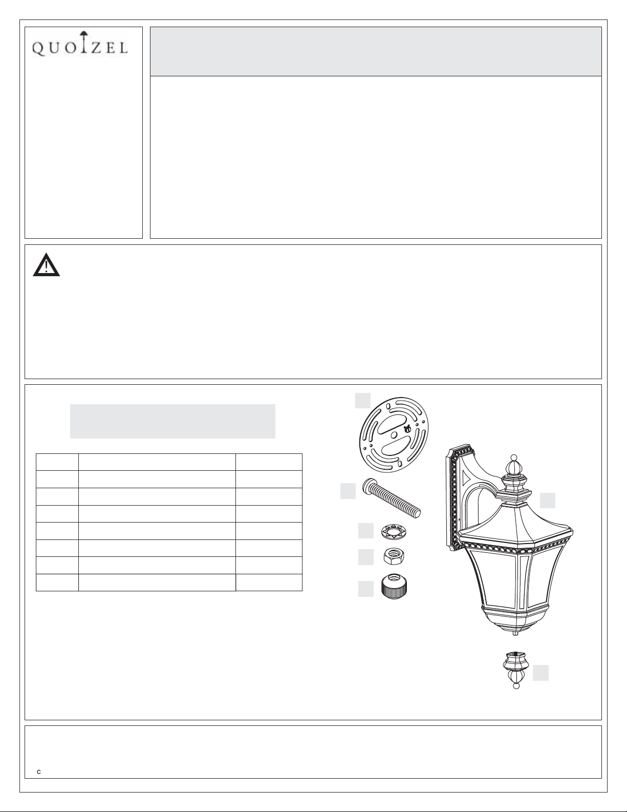
Package Contents
Part
A Crossbar
B
C
D
E
F
G
Description
Mounting Screw
Lock Washer
Hex Nut
Mounting Ball
Fixture Body
Finial Assembly
Quantity
1pc.
2 pcs.
2 pcs.
2 pcs.
2 pcs.
1pc.
1pc.
B
F
C
D
E
Need assistance with parts or assembly? Call Quoizel customer service at 1-631-273-2700
2011 Quoizel Inc.
Thank you for purchasing a Quoizel product.
or visit us on-line at www.quoizel.com
1of6
G
August2011
Page 2
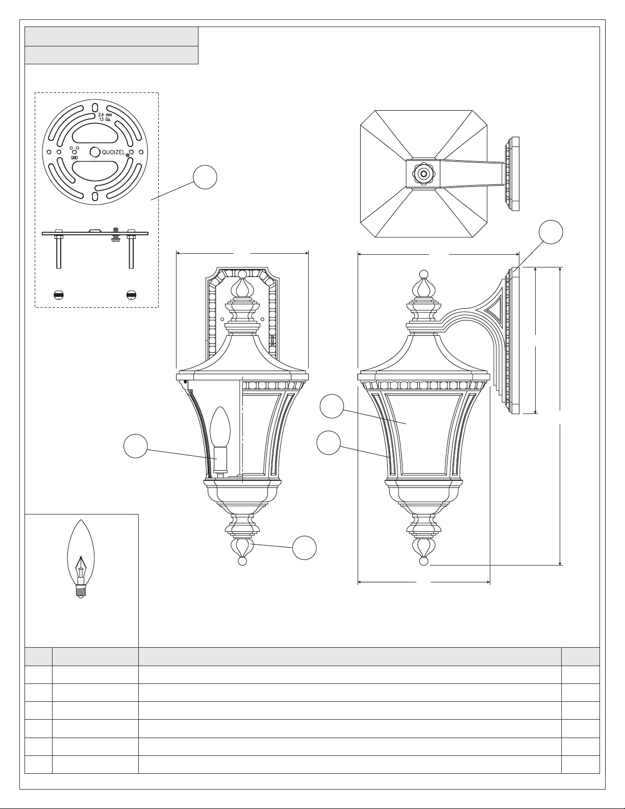
DE8976IB
FINISH: IMPERIAL BRONZE
4
1
2
9”
11”
10”
5
21”
6
(2)60W Candelabra
base bulbs
(not Supplied)
PART NUMBER
NO.
18976IBDE
1
2
3
4
5
6
M380CCIB
M387FIIB
M280KTIB
G1198PA
G1197PA
3
NOTE: ALL DIMENSIONS ARE ROUNDED UP TO THE NEAREST 1/2"
REPLACEMENT PART DESCRIPTION
BASE IMPERIAL BRONZE DE8976IB
CDCV IMPBRZ REPL CANDLE COVER
FINL IMPBRZ REPL DE8959/8976IB
KIT IMPR BRNZ REPL
PANL LRG CLR BEV REPL DE8959IB
PANL SML CLR BEV REPL DE8959IB
2of6
9”
REQ.
1
2
1
1
4
4
Page 3

6 CORPORATE PARKWAY
GOOSE CREEK SC 29445
www quoizel com
..
,.
Assembly Instruction Sheet #IS-DE8976IB
For Styles DE8976IB
STEP 1 Remove Glass Frame from Fixture
-
Hood
A. Prior to assembly, remove the Glass Frame from the
Fixture Hood by unscrewing the Hex Coupling. Remove
the packaging material inside of the Glass Frame.
STEP 2 - Attach Mounting Screws, Lock
Washers and Hex Nuts to Crossbar
A. Line up a set of holes on the Crossbar (A) and Holes on
the backplate of the Fixture Body (F).
B. Thread Mounting Screws (B) into the holes on the
Crossbar (A), pass Lock Washers (C) and thread Hex
Nut (D) onto the Mounting Screws (B). Hand tighten
until snug.
Figure 1
Mounting
Screw
Fixture Body
Fixture
Hood
Glass
Frame
Hex
Coupling
Lock Washer
Hex Nut
STEP 3 - Attach Crossbar to Outlet Box
A. Attach the Crossbar (A) to Outlet Box and secure by
threading Outlet Box Screws (not supplied) into the
Mounting Holes on the Outlet Box. Tighten until snug.
Thank you for purchasing a Quoizel product.
Need assistance with parts or assembly? Call Quoizel customer service at 1-631-273-2700
2011 Quoizel Inc.
or visit us on-line at www.quoizel.com
3of6
Crossbar
Figure 2
Mounting
Hole
Fixture
Body
Figure 3
Outlet
Box
Crossbar
Outlet Box
Screw
August2011
Page 4

6 CORPORATE PARKWAY
GOOSE CREEK SC 29445
www quoizel com
..
,.
Assembly Instruction Sheet #IS-DE8976IB
For Styles DE8976IB
STEP 4 Attach Lanyard-
A. The purpose of the lanyard is to provide the installer a
means to support the fixture from the junction box while
connecting the electrical wires. This enables the fixture
to hang from the junction box and your hands are free to
make the wire connections.
B. TurntheButtonStopsoitmaybeinsertedintothe
crossbar slot. Make sure the Button Stop is completely
inside the crossbar. Slowly release the fixture to make
sure it is supported by the Button Stop. Proceed to the
wiring steps. Once you are complete with the wiring
there is nothing to do with Lanyard. The Lanyard will
push into the junction box when the fixture is placed for
final mounting.
STEP 5 Make Wire Connections-
A. Use standard wire connectors to make all wire
connections. (Connectors are not included with fixture.)
Strip and prepare wire ends according to instructions
supplied with connectors.
B. Connect White Supply Wire from the Outlet Box to White
Wire from fixture.
C. Connect Black (or Red) Supply Wire from the Outlet Box
to Black Wire from fixture.
D. Connect Ground Wire from the Outlet Box to Ground
Wire from fixture.
E. Twist connectors until wires are tightly joined together.
F. Wrap each connection with approved electrical tape and
carefully stuff all the connected wires into the Outlet Box.
Crossbar
Button Stop
Slot
Lanyard
Figure 4
Figure 5
White wire from supply White wire from fixture
Black wire from supply
(or Red)
Ground wire from supply Ground wire from fixture
Black wire from fixture
Figure 6
Thank you for purchasing a Quoizel product.
Need assistance with parts or assembly? Call Quoizel customer service at 1-631-273-2700
2011 Quoizel Inc.
or visit us on-line at www.quoizel.com
4of6
August2011
Page 5

6 CORPORATE PARKWAY
GOOSE CREEK SC 29445
www quoizel com
..
,.
Assembly Instruction Sheet #IS-DE8976IB
For Styles DE8976IB
STEP 6 - Attach Fixture Body to Mounting
Screw
A. Place the backplate of the Fixture Body (G) over the
Mounting Screws (B) and secure with Mounting Balls
(E). Hand tighten until snug.
STEP 7 Install Bulb-
A. This fixture uses standard bulb with a candelabra screw
base. Maximum 60 watts.
B. Insert bulb and screw snugly into place.
Figure 7
Mounting Screw
Backplate
Mounting Ball
Bulb
Socket
STEP 8 Attach Glass Frame to Fixture Hood-
A. Place the Glass Frame over the end of the Stem on the
bottom center of the Junction Box. Attach to the Fixture
Hood. Secure by threading the Hex Coupling onto the
Stem and tighten until snug.
Thank you for purchasing a Quoizel product.
Need assistance with parts or assembly? Call Quoizel customer service at 1-631-273-2700
2011 Quoizel Inc.
or visit us on-line at www.quoizel.com
5of6
Figure 8
Fixture
Hood
Junction Box
Stem
Glass Frame
Figure 9
Hex Coupling
August2011
Page 6

6 CORPORATE PARKWAY
GOOSE CREEK SC 29445
www quoizel com
..
,.
Assembly Instruction Sheet #IS-DE8976IB
For Styles DE8976IB
STEP 9 - Assemble Strut Member and Finial
A. Remove the Strut Member and the Nipple from the Finial.
B. Screw one end of the Nipple into the Hex Coupling on the
bottom center of the Fixture Body (F). Hand tighten until
snug.
C. Pass the Strut Member over the top end of the Nipple and
secure with the Finial. Hand tighten until snug.
STEP 10 Apply Silicone Sealer to Mounting
-
Balls
A. To prevent moisture from entering the wire
compartment, apply a small amount of silicone sealer
(not included) to the threaded side of the mounting
balls (E) and then install them onto the mounting
screws (B). Wipe off excess caulk.
Figure 10
Fixture Body
Hex Coupling
Nipple
Strut Member
Finial
Mounting Ball
STEP 11 Apply Silicone Sealer to Backplate-
A. Make sure exterior wall surface and fixture backplate
are free of dirt before applying caulk. Using exterior
grade caulk, start on one side of fixture backplate and
follow contour, where the fixture backplate meets the
exterior wall surface upward. Proceed to caulk over top
of backplate and down other side. Do not caulk bottom
of fixture backplate to ensure proper moisture
drainage.
Your lamp wall fixture is now assembled and ready to
use. Enjoy!
Figure 11
Exterior
Wall Surface
Outdoor Fixture
Backplate
Figure 12
Exterior
Grade Caulk
Need assistance with parts or assembly? Call Quoizel customer service at 1-631-273-2700
2011 Quoizel Inc.
Thank you for purchasing a Quoizel product.
or visit us on-line at www.quoizel.com
6of6
August2011
 Loading...