

Page 1
Assembly Instruction Sheet #IS-BRN8412IB
For Style BRN8412IB
Quoizel, Inc.
6 Corporate Parkway
Goose Creek, SC 29445
Customer Service
Phone 631.273.2700
Fax 631.231.7102
www.quoizel.com
ToolsRequired: Flatheadscrewdriver, Phillipsscrewdriver,pliers,wire cutters, wire strippers, electricaltape,
safetyglasses.
BulbRecommended:
bulb(2) 23W CFL Maximum.
EstimatedAssembly Time:
Preparation:
belowto be sure all partsarepresent. If any parts aremissing or damaged, do not attemptto assemble, install, or
operatethe fixture. Contact customer serviceforreplacement parts.
Fixturecan only be mounted inthedirection indicated on page 2.
Identifyand inspect all parts beforebeginninginstallation. Check package content listand diagrams
(2)Medium Base Decorative Filament 60Wbulbs(provided), Maximum 100W,Alternate
30-45minutes
Warnings and Cautions
Turn off electricity at circuit breaker or main fuse box before installation. Consult a licensed electrician if in doubt.
These instructions are provided for your safety. It is very important you read them completely before installing the fixture. We strongly
recommend that a licensed, professional electrician perform the installation.
Disconnect fixture from power source before replacing bulbs. Make sure bulbs are given sufficient time to cool before removal. Do not subject
glass parts to any shock while in operation or shattering may result.
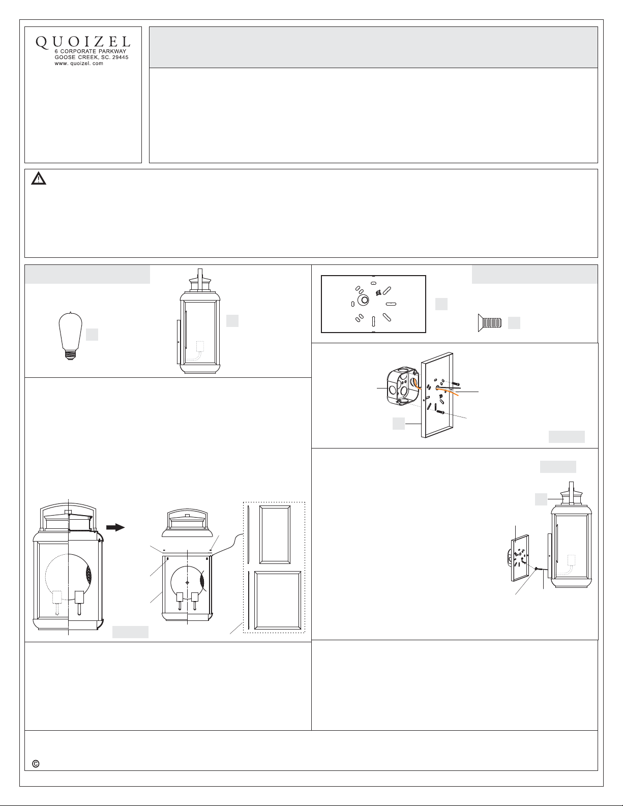
Package Contents
Bulb
A
x2
B
AA
Fixture
x1
Hardware Contents
Inner Backplate
x1
Lock Screw
BB
x2
STEP 1 Adjust the Glass panels-
Remove the fixture from the package and check glass panels. If
there are any loosen glass panels, please refer to the follows to
make adjustment.
A. Remove the Cage from the Fixture by unscrewing Lock Screws.
B. Remove the Glass Panel Holder from the top of the Cage by
unlocking Hex Nuts.
C. Adjust Glass Panels to proper location and then secure with the
removed Glass Panel Holder. Hand tighten until with Hex Nuts.
D. Place Cage back onto Fixture and secure with Lock Screws.
Glass
Panel
Holder
Lock
Screw
Cage
Figure 1
STEP 2 Install Inner Backplate-
A. Pass the supply wires through the existing hole on the Inner
Backplate (AA).
B. Inner BackplateAttach the (AA) to the Outlet Box with the head of
the Green Ground Screw facing you. Secure it with Outlet Box
Screws (not included). Tighten until snug.
Glass Panel
Hex
Nut
Outlet Box
AA
STEP 3 - Attach Lanyard
A. The purpose of the lanyard is to provide
the installer a means to support the
fixture from the junction box while
connecting the electrical wires. This
enables the fixture to hang from the
junction box and your hands are free to
make the wire connections.
B. TurntheButtonStopsoitmaybe
inserted into the Inner Backplate slot.
Make sure the Button Stop is completely
inside the Inner Backplate. Slowly
release the fixture to make sure it is
supported by the Button Stop. Proceed
to the wiring steps in the next step. Once
you are complete with the wiring there is
nothing to do with Lanyard. The Lanyard
will push into the junction box when the
fixture is placed for final mounting.
STEP 4 - Wire Connections
A. Use standard wire connectors (not included) to make all wire
connections. (Connectors are not included with fixture.) Strip and
prepare wire ends according to instructions supplied with
connectors.
B. Connect White Supply Wire from the Outlet Box to Ribbed side Wire
from fixture.
C. Connect Black (or Red) Supply Wire from the Outlet Box to Smooth
Supply Wires with
Ground Wire
Outlet Box Screws
(not included)
Inner
Backplate
Lanyard
Button
Stop
Figure 2
Figure 3
B
2014 QuoizelInc.
Need assistance with parts or assembly? Call Quoizel customer service at 1-631-273-2700
Thank you for purchasing a Quoizel product.
or visit us on-line at www.quoizel.com
1of2
April2014
Page 2
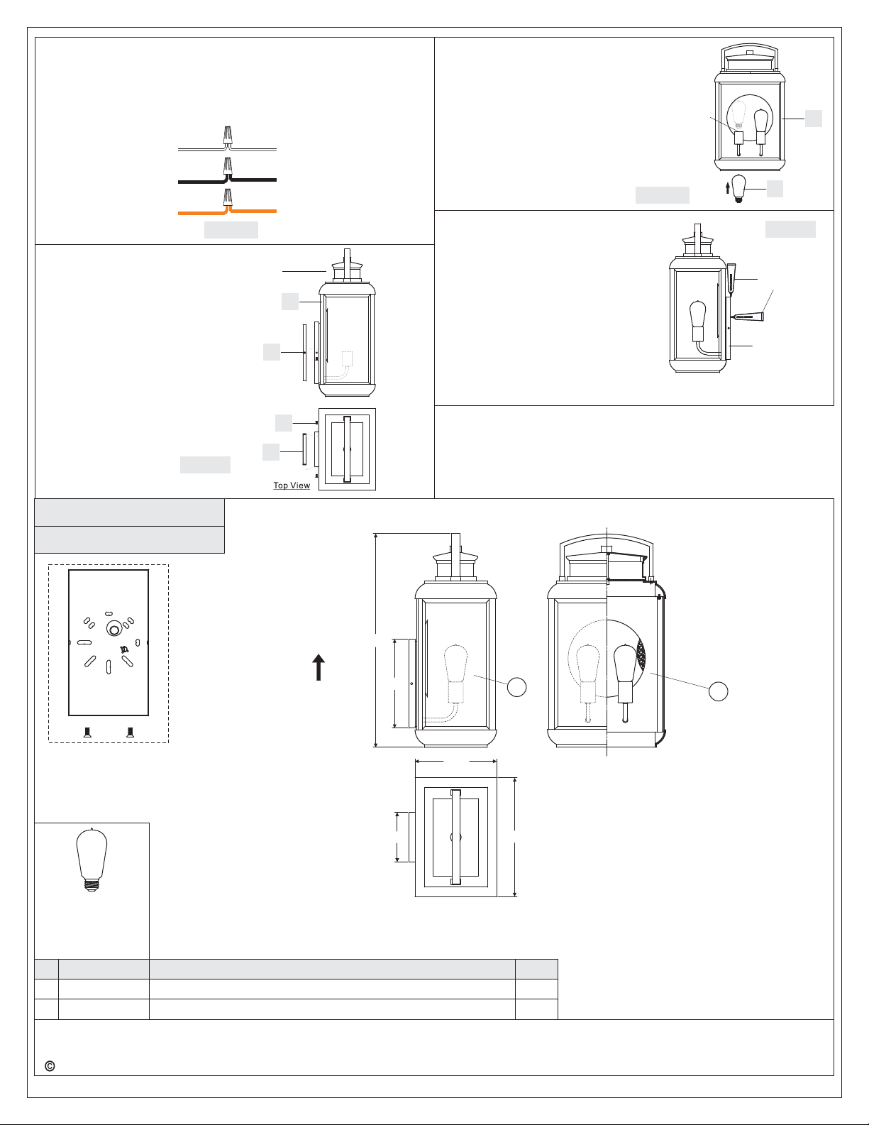
side Wire from fixture.
D. Connect Ground Wire from the Outlet Box to Ground Wire from
fixture.
E. Twist connectors until wires are tightly joined together.
F. Wrap each connection with approved electrical tape and carefully
stuff all the connected wires into the Outlet Box.
White wire
from supply
Black wire from
supply (or Red)
Ground wire
from supply
STEP 5 Install Fixture to Inner
A. Attach the Fixture (B) over the
-
Backplate
Inner Backplate (AA) and
secure with the Lock Screws
(BB). Tighten until snug with
screwdrivers.
Figure 4
Ribbed side wire
from fixture
Smooth side wire
from fixture
Ground wire
from fixture
Front View
B
AA
BB
STEP 6 Install Bulb-
A. This fixture uses standard bulb with
medium base . Maximum 100 watts.
B. Insert bulb and screw snugly into
place.
STEP 7 - Apply Silicone Sealer
A. Make sure exterior wall surface and
fixture backplate are free of dirt
before applying caulk. Using
exterior grade caulk, caulk over top
of backplate and down other side.
Do not caulk bottom of fixture
backplate to ensure proper
moisture drainage.
Your fixture is now assembled and
ready to use. Enjoy!
Socket
Figure 6
B
A
Figure 7
Exterior
Grade Caulk
Backplate
Figure 5
BRN8412IB
FINISH: IMPERIAL BRONZE
AA
Fixture can only be
mounted in the
direction indicated
21.5”
9”
5”
8.5”
1
12”
2
(2)Medium Base
Decorative
Filament 60W
bulbs (provided),
Maximum 100W.
PART NUMBER
NO.
1
G3828PA
2
G3829PA
2014 QuoizelInc.
NOTE: ALL DIMENSIONS ARE ROUNDED UPTO THE NEAREST 1/2"
REPLACEMENT PART DESCRIPTION
GLASS PANEL CLEAR BEVELED
GLASS PANEL CLEAR BEVELED
Thank you for purchasing a Quoizel product.
Need assistance with parts or assembly? Call Quoizel customer service at 1-631-273-2700
or visit us on-line at www.quoizel.com
2of2
REQ.
2
1
April2014
 Loading...