


User Ma
S404
201
2015
5
RoketGT

Content
1.
1. Product Introduction .............................................................................................................................. 2
1.2. How to Work .......................................................................................................................................... 2
1.3. Package Content..................................................................................................................................... 3
1.4. Host Unit Layout .................................................................................................................................... 4
2.1. Host Unit Installation/Cigarette lighter Connection .............................................................................. 4
3.1. Tire Sensor-Position ............................................................................................................................... 5
3.2. Tire Sensor-Battery Installation ............................................................................................................. 5
3.3. Tire Sensor-Installation on Tire .............................................................................................................. 5
3.4. Frequently Asked Questions (FAQ) ........................................................................................................ 6
4.1. Function and Setting Button .................................................................................................................. 7
4.2. Operating of Main Screen ...................................................................................................................... 8
4.3. Wireless Signal Received of Tire Sensor................................................................................................. 8
4.4. Tire Surveillance Analysis(TSA) .............................................................................................................. 9
5.1. Function and Setting ............................................................................................................................ 10
5.2. Limit Setting of Tire Pressure / Temperature ....................................................................................... 11
5.3. Unit Setting of Tire Pressure / Temperature ........................................................................................ 12
5.4. Car Model/Tire Model ......................................................................................................................... 12
5.5. Sensor Alignment ................................................................................................................................. 14
5.6. Time Setting ......................................................................................................................................... 15
5.7. Default Setting ..................................................................................................................................... 16
7.1. Specifications ....................................................................................................................................... 17
8.1. Notice ................................................................................................................................................... 17
1.1
1.2
Tire wi
Moni
Prod
How
Tire pressur
Tire Tempe
Tire sensors
on
Introd
ciga
lighte
TPM
TiTiTiTiPr
SugTiTiTiTiRe
ressure
on
Prom
Leaki
Surveilla
eatures
(T
onit
Lower/Uppe
empera
Abnormal
nalysi
(TSM)
Di
larm
Temperatur
F
onitor
T
is Rising C
Air
A
RTC)
larm
Alarm
TSA)
is shown
’s:
with

1.3. P
(Host package)
Host unit(TFT LCD) 1
Cigarette lighter Cable 1
Tire sensor 10
Tire sensor battery (CR1632) 10
Anti-thief nut 10
(Tire sensor spanner) 1
Mounting bracket 1
Antenna 1
Antenna mounting bracket 1
Antenna extension cable (including convertor) 1
User manual 1
ackage Content
Description Q’ty(Pcs)
(Accessories package)
Description Q’ty(Pcs)
Tire sensor 12
Tire sensor battery (CR1632) 12
Anti-thief nut 12
(Tire sensor spanner) 1
(Position sticker) 1
User manual 1
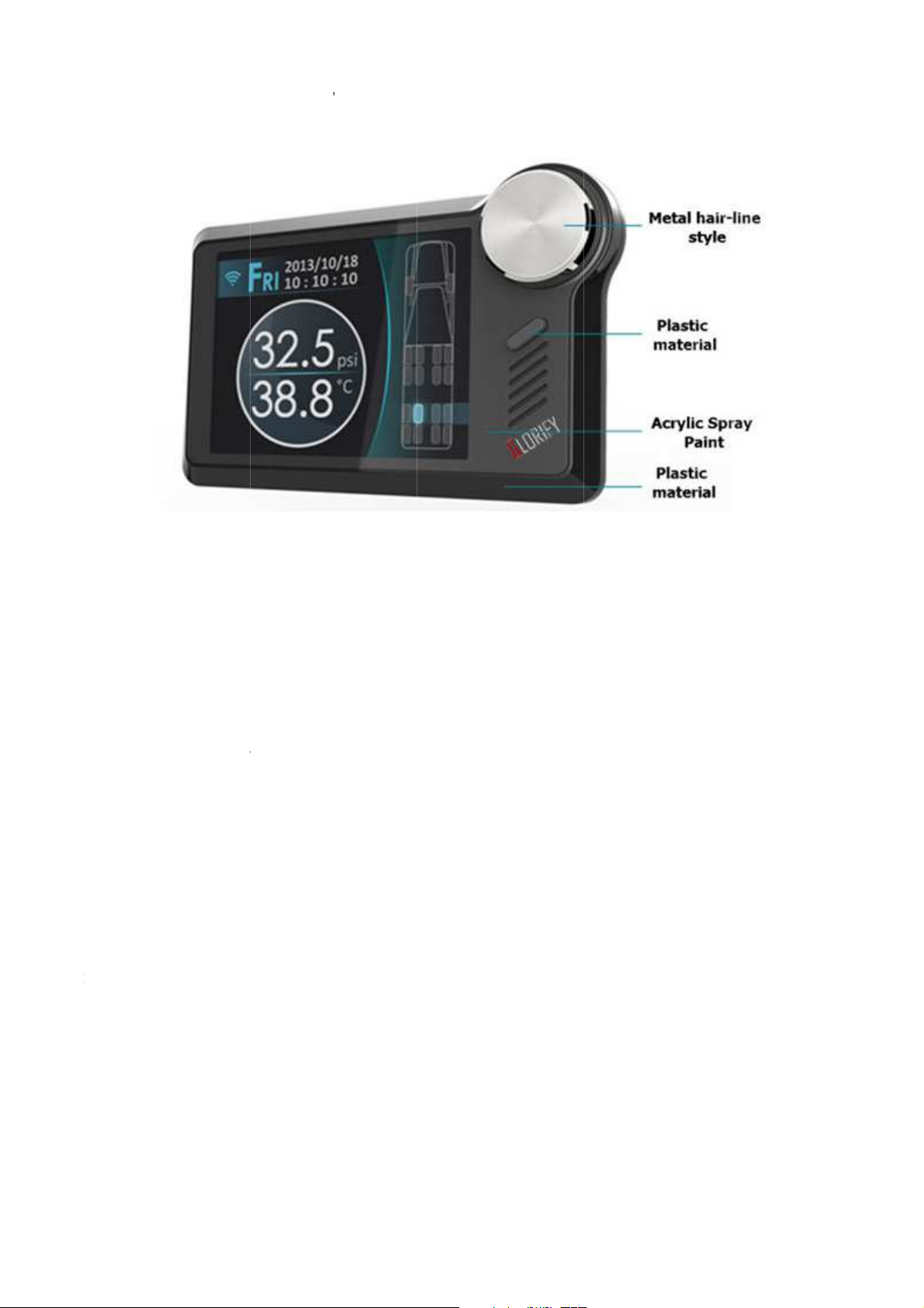
1.4
2.1
Step
Step
Note
f eng
avoid
Hos
Hos
Conne
Connec
Connector
onnector o
the
TFT LCD wil
of circle sha
tha
ed
of vehi
ngine is
automatic
of ho
consum
power po
cigar
will not
with
Jack)
lighter
unplug th
(1)
(2)
(1)
(2)
I
:
C
:
Turn on
:
be boot
ower
ed.
.
.
(DC-
.

3.1. T
ire Sensor-Position
Step 1
The sensors positions come with individual label to indicate the position from the tire.
The sensors shall be installed according to the design position.
Tire sensors position and label
:
3.2. Tire Sensor-Battery Installation
Step 2
The tire sensors come with Lithium CR1632 original Swiss made military spec. battery.
(1) Prepare the sensor battery CR1632 Lithium, locate and understand the +/- polarity.
(2) Remove sensor cap by unscrew it from the sensor metal body.
(3) Remove the battery metal cover by unclip the both clips (short and long clips).
(4) Place the battery in correct polarity.
(5) Place the battery cover in place and press the both clips with proper closure.
Tire Sensor Battery Installation
:
(6) Close the sensor cap by screwing tightly.
(7) In order the tire sensor work properly, the screen of host tire sensor battery reading shall be minimum
2.8 Voltage. Replace sensor battery when voltage reading under 2.8 Voltage.
3.3. T
tep 3
S
Before installation please is sure the position of each sensor shall be correctly placed.
(1) Remove tire-valve cap
(2) Screw-in of clockwise direction the safety lock not into tire-valve.
(3) Place the tire sensor on designated position.
(4) Screw it tightly.
(5) Screw-in of counterclockwise direction that sensor and anti-thief nut tightly with dedicated spanner.
Note:
:
ire Sensor-Installation on Tire
Installation Tire Sensor on vehicle tire
The tire sensor shall be fitted and screw tightly to avoid tire pressure leakage.

3.4. F
(1) FAQ 1:After Host turned on for 5 minutes, it still shows failure of receiving wireless signal
Solution:
1. Please make sure if the batteries are in reverse.
2. Please make sure the snap of battery is in close of the batteries.
3. Please make sure if voltages in the batteries are enough; please replace with new ones if less
4. Please disassemble the battery, replace the battery once.
5. Please turn the lid off and check if penetration of any vapor occurred which caused battery snap
6. Make sure an antenna installation and check connection between a SMA port on host side and
(2) FAQ 2:The tire always shows-when one doesn’t get data of RF signal.
Solution:
requently Asked Questions (FAQ)
(Negative is poured at bottom side and positive at upper side)
than 2.8 Voltage.
or rust and malfunction.
extend antenna tightly.
1. Please go away there. (Perhaps it has strong interference of wireless signal)
2. Please check power of sensor battery, please replace new battery it if one is less than 2.8 voltage.
3. Please contact with dealer.
(3) FAQ 3:I bought this product, but tire sensor is no label such as repeat and lost what I can do?
Solution:
We already have paired sensor with host, please contact with dealer if your problem as below.
Note
T
he system is operated on wireless signal, under certain situation, the system may be unable to receive or
reduce down the wireless signal as a result of environment intervention, mistakes made during operation
and improper installation.

4.1
Fun
on

4.2
4.3
Ope
The
Wir
Host will be
from
ll sensors
anim
Press
Check warning icon
Yes
screen save
top
Setting button
left corne
Press
Show the tire information
and wireless signal
Setting screen
Show next tire
seconds
Press
Show the tire information and wireless signal
Choice tire positi
with Rotary
Screen save
separate
or r
when hos
Setting button
TSA screen
Cho
Enter button
Warning screen
Show
tire
when eng
Press
seconds
Enter button
Check warning icon
Jump
Yes
Check
No
per 5
with Rotary
No
Jump
[
]
Main screen
[
[
]
]
5
[
]
No
Yes
(1)
colors
(2)
A
(3)
Show
-
.

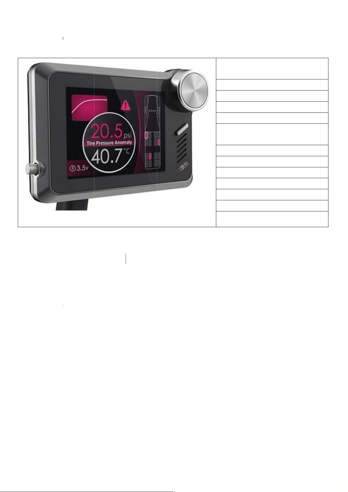
4.4. T
(1) TSA which show detail information such as tire pressure/temperature by time curve
(2) Tire pressure curve as above and tire temperature as below.
(3) User can choose timeline(x- axle) with Rotary that easy to show point of time.
(4) Top-left corner on screen show date and time.
(5) Middle-left corner on screen show tire pressure of custom time, middle-corner on screen show
abnormal status if it has occur.
(6) Bottom-left corner on screen show tire temperature of custom time, bottom-middle on screen show
current page/total page.
Record time of tire
pressure/temperature
ire Surveillance Analysis (TSA)
Tire pressure
Tire temperature
Abnormal status
TSA screen

5.1. F
(1) Setting as below
A. P. U-Limit (Set Tire Pressure Upper Limit)
B. P. L-Limit (Set Tire Pressure Lower Limit)
C. T. Limit (Set Tire Temperature Limit)
D. P. Unit (Set Tire Pressure Unit)
E. T. Unit (Set Tire Temperature Unit)
unction and Setting
Set tire pressure upper limit, it will be shown abnormal status if value of tire pressure is more
than your setting.
Set tire pressure lower limit, it will be shown abnormal status if value of tire pressure is less than
your setting.
Set tire temperature upper limit, it will be shown abnormal status if value of tire temperature is
more than your setting.
Switch unit of pressure as psi, bar, kg/cm2 & kPA.
Switch unit of temperature as ℃ & ℉.
F. Car Model
There are ten type of car model can be chosen.
G. Sensor Align
User can be swapped/replace/pair by this function.
H. Time Setting
Host provides RTC(Real Time Clock) function, please set time if you need TSA function.
I. Screen Save
Set time of screen save which has 1、2 and 5 minute for choice. It will be disabled if warning
status.
J. Language
There are languages what you can choose English and traditional Chinese .
K. Default
Help user to set up all functions.

5.2. Limit Setting of Tire Pressure / Temperature

5.3. U
nit Setting of Tire Pressure / Temperature
5.4. Car Model/Tire Model
There are ten models of car as below:
(1) Single Tow
(2) Motorhome T1
(3) Motorhome T2
(4) Caravan
(5) Tourbus
(6) Truck
(7) Pickup
(8) Sedan
(9) Hatchback
(10) Car
Host will apply when you set up completed


5.5. Sen
sor Alignment
Sensor alignment
Choice current tire with Rotary
Show current tire of blue color
Prompt sensor ID message
Replace tire sensor ID
Check current tire
pair sensor ID
Show current tire of yellow color
Prompt no sensor ID message
Pair sensor ID
1.Attached sensor label according to
current sensor on screen
2.Host will pair sensor when you
install battery to sensor
Exit
Install battery into sensor screw in cap of sensor

5.6. T
ime Setting

5.7. De
fault Setting

 Loading...