


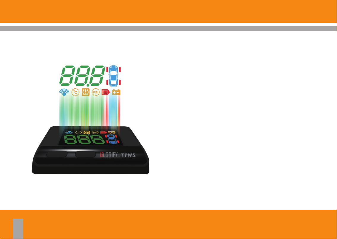
TPMS PRO
&RocketIN
Vehicle Wireless TPMS HUD
T204-I
S306
User Manual


Content
Table of Content
1.1 Introduction of Product Safety.
1.2 w It Works.Ho
‧‧‧‧‧‧‧‧‧‧‧‧‧‧‧‧‧‧‧‧‧‧‧‧‧‧‧‧‧‧‧‧‧‧‧‧‧‧‧‧‧‧ ‧‧‧‧‧ ‧‧‧‧‧ ‧‧‧‧‧
1.3 s-Up Display (HUD) Technology.Head
1.4 ge Content.Packa
1.5 HUD Unit Lay Out.
‧‧‧‧‧‧‧‧‧‧‧‧‧‧‧‧‧‧‧‧‧‧‧‧‧‧‧‧‧‧‧‧‧‧‧‧‧‧‧‧‧‧ ‧‧‧‧‧ ‧‧
‧‧‧‧‧‧‧‧‧‧‧‧‧‧‧‧‧‧‧‧‧‧‧‧‧‧‧‧‧‧‧‧‧‧‧‧‧‧‧‧‧‧ ‧‧‧‧‧ ‧‧‧
‧‧‧‧‧‧‧‧‧‧‧‧‧‧‧‧‧‧‧‧‧‧‧‧‧‧‧
‧‧‧‧‧‧‧‧‧‧‧‧‧‧
2.1 HUD Unit and Cigarette lighter Connection.
2.2 Sticking the Reflective-Film.
2.3 Sticking the VELCRO Tape.
‧‧‧‧‧‧‧‧‧‧‧‧‧‧‧‧‧‧‧‧‧‧‧‧‧‧‧‧‧‧‧
‧‧‧‧‧‧‧‧‧‧‧‧‧‧‧‧‧‧‧‧‧‧‧‧‧‧‧‧‧‧‧‧‧‧
3.1 Tire Sensor / Position (Marking on sensor).
3.2 Tire Sensor Installation.
‧‧‧‧‧‧‧‧‧‧‧‧‧‧‧‧‧‧‧‧‧‧‧‧‧‧‧‧‧‧‧‧‧‧
‧‧‧‧‧‧
02
03
04
05
06
‧‧‧
07
08
09
3.3 Tire sensor / Installation On Vehicle Tire.
3.4 Installation FAQs
4.1 HUD-HUD Operating Instructions
‧‧‧‧‧‧‧‧‧‧‧‧‧‧‧‧‧‧‧‧‧‧‧‧‧‧‧‧‧‧‧‧‧‧‧‧‧‧‧‧‧‧ ‧‧‧‧‧ ‧‧‧
‧‧‧‧‧‧‧‧‧‧‧‧‧‧
4.2 HUD-Receiving RF Signal From Tire Sensors.
5.1 HUD-Function and Setting.
5.2 Quick Check Tire Condition.
5.3 HUD-Warnings and Legends.
6.1 Product Speciflcations.
‧‧‧‧‧‧‧‧‧‧‧‧‧‧‧‧‧‧‧‧‧‧‧‧‧‧‧‧‧‧‧‧‧
‧‧‧‧‧‧‧‧‧‧‧‧‧‧‧‧‧‧‧‧‧‧‧‧‧‧‧‧‧‧‧‧‧
‧‧‧‧‧‧‧‧‧‧‧‧‧‧‧‧‧‧‧‧‧‧‧‧‧‧‧‧‧‧‧
‧‧‧‧‧‧‧‧‧‧‧‧‧‧‧‧‧‧‧‧‧‧‧‧‧‧‧‧‧‧
‧‧‧‧‧‧‧‧‧
‧‧‧‧‧‧
12
13
15
16
17
18
19
20
10
11
TPMS PRO
1.1 Introduction of Product Safety
TPMS PRO 8 in 1 Feature s
Ÿ Heads-Up Display(HUD).
Ÿ Tire pressure monitoring(TPM)
Ÿ Tire temperature monitoring.
Ÿ Low pressure tire warning alarm.
Ÿ Over pressure tire warning alarm.
Ÿ Over tire temperature warning alarm.
Ÿ Vehicles battery voltage monitoring.
Ÿ TPMS tire sensor battery voltage monitoring.
02
TPMS PRO
Tire Sensor Tire Sensor
Tire SensorTire Sensor
Tire wireless sensors transmitting data’s:
Ÿ Tires pressure.
Ÿ Tires temperature.
Ÿ Tire sensors batteries voltage.
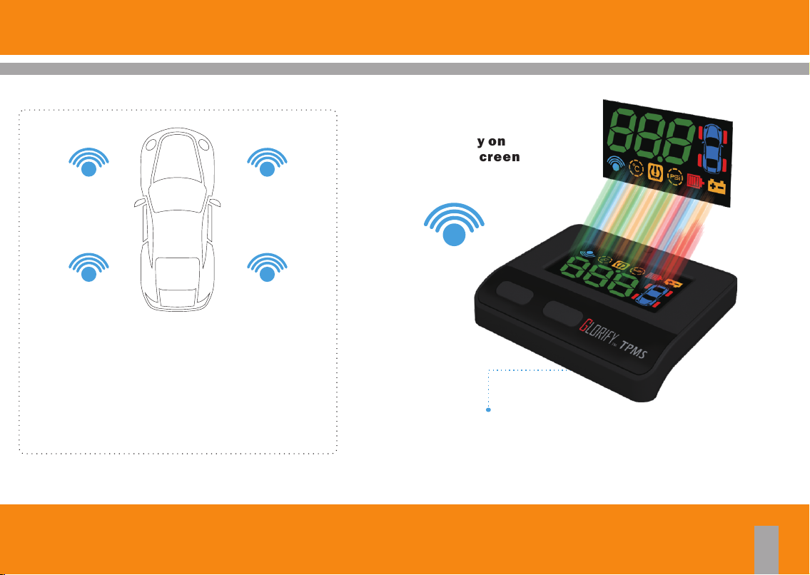
1.2 How It Works
HUD display on
vehicle w indscreen
RF
Link provided by the host HUD cigarette lighter power
TPMS PRO
03

1.3 Heads-Up Display (HUD) Technology
HUD(Heads-Up Display) Technology firstly developed for
military and commercial aviation to help pilot being able to
view real time data on the windshield or helmet without looking
down the lower side instrument.
04
TPMS PRO

1.4 Package Content
Descripti ons
HUD (Heads- Up D isplay) U ni t
Cigarette L ighter Power Cab le
HUD Refle ctive Fil m
HUD Fitting Accessorie s
Tire Sensor
User Manual
Warra nty Card
Q’ty (Pcs)
1
1
1
2
4
1
1
TPMS PRO
05

1.5 HUD Unit Lay Out
HUD display automatic
illumination sensor
Power connector
Power switc h
Heads-Up Display
SETTING Button
FUNCTION Button
06
TPMS PRO

2.1 HUD Unit and Cigarette lighter Connection
Step 1 :Locat e the vehic le cigarett e lighter
(1) Search position of Host Unit.(Figure 1)
(2) Cigarette lighter Connector.(Figure 2)
Step 2: To confirm t he screen tur ns on automat ically
(1) Turn on the engine.
(2) Turn on the switch of the HUD unit.(Figure 3)
(3) Wait the screen turn on automatically.(Figure 4)
Figure 1 Figure 2 Figure 3
Instruction :
1. If Cigaret te lighter, turn of f the engine, the p ower will b e shut down, th e host switch nor mally open.
2. If engine is s hut down, the p ower will n ot turn off will be required to host the r ear of the switch to turn off
or unplug the c igarette lighter plug to prevent batt er y power deple tion.
Figure 4
TPMS PRO
07

2.2 Sticking the Reflective-Film
Step 3 : Sticking t he reflecti ve film
(1) Clean the windshield reflective area. (Figure 5)
(2) Take off the release film, spray soap water both on windshield and reflective film (Figure 6), place absorbent
material below to prevent water dripping on dashboard. (Figure 7)
(3) Stick the reflective film on windshield and align it properly. (Figure 8)
(4) Scratch out air and water between reflective film and glass windshield than clean. (Figure 9)
(5) Wait until reflective film dry. (Figure 10)
08
Figure 5
Figure 6
TPMS PRO
Figure 7
Figure 8Figure 9Figure 10

2.3 Sticking the VELCRO Tape
Step 4 : Sticking t he VELCRO t ape
(1) Stick the VELCRO tape at the bottom side of HUD unit. (Figure 11)
(2) Tear-off the release film. (Figure 12)
(3) Stick the VELCRO tape on designated vehicle dashboard area.
(4) Place the HUD unit. (Figure 13)
Figure 11
Figure 12 Figure 13
TPMS PRO
09

3.1 Tire Sensor / Tire Sensor Position
Step1 : Tire sensors position and label
The tire sensors position come with individual label to indicate the position from the tire.
The tire sensors shall be installed according to the designation position. (Figure 14)
LF (L1)
LR (L2)
10
RF (R1)
L1 Left Front
L2 Left Rear
R1 Right Front
R2 Right Rear
RR (R2)
Figure 14
TPMS PRO

3.2 Tire Sensor Installation
Step2 : Tire sensors inst al lation for per tire
Please make sure labels before installation and follow position of tire.
1.Get a sensor. (Figure 15)
2.Remove tire-valve cap and screw nut.(Figure 16)
3.Install sensor from internal hole of rim to external.(Figure 17)
4.Install screw nut.(Figure 18)
Figure 15
Figure 16
TPMS PRO
Figure 17
Figure 18
11

3.3 Tire sensor / Installation On Vehicle Tire
Step2 : Tire sensors inst allation for per tire
5.Lock screw nut with hands.(Figure 19)
6.Adjust an angle of sensor with hex key.(Figure 20)
7.Fix sensor with wrench and torque wrench about 40~45kgf-cm (4~4.5Nm) Figure 21).(
8.Lock tire-valve cap after inflated tire. Figure 22)(
12
Figure 19
Figure 20
TPMS PRO
Figure 21
Figure 22

3.4 Installation FAQs
FAQ 1:How to reset position of tire if I need rotate tires?
Solution:
1.Please turn off Host unit and confirm power off. (Figure 23)
2.Press function and setting button simultaneously, then turn on host unit about 5 seconds will be into learning
mode.(Figure 24)
3.It will be flashed current position sequentially as L1,R1,R2,L2.
4.Follow position of flashing and inflating one, then host unit will be received signal and setup it changes next
position until all positions learned.(Figure 25)
Pow er swit ch
Set ting bu tton
Fun ction b utton
Figure 23
Figure 24
Figure 25
TPMS PRO
13

3.4 Installation FAQs
FAQ 2: When a tire position for 5 minutes did not receive RF signals, and see a red icon lights up of the tire position.
Solution:
(1) Please drive the vehicle to leave this area (may have a strong radio signal interference in the vicinity)
(2) Make sure the battery is suf ficient, if less than 2.6 V battery should be replaced new sensor.
(3) Please contact your dealer for assistance.
FAQ 3: If the purchased products that no sticker af fixed to the wheel position sensors, round stickers duplicated or fall, how to do?
Solution:
When production, HUD unit and four sensor settings have been completed, subject to the above questions, please contact your
dealer to reset, to avoid placing the sensor position error.
Instruction :
The system is bas ed on the operation of the wirel ess signal, in some special cases, the system m ay be due to
environme ntal interference, incorrect operation or i mproper insta llation, resulting in redu ced or unable to
receive radio signals.
14
TPMS PRO

4.1 HUD Operating Instructions
Function button:
Press the function button to cycle through the various functions in the battery voltage screen (main screen).
Setting button:
Press the setting button to change the settings in the temperature/pressure limit setting screen.
Press the setting button to show tire temperature/pressure and sensor voltage in others.
Functio n Button Setting But ton
Battery(VOLT)
Tire Temperature Upper Limits Settings
Tire Pressure lower Limits Settings
Tire Pressure Bottom Limits Settings
TPMS PRO
Tire Pressure Display
Tire Temperature Display
Battery Voltage Display
15

4.2 HUD-Receiving RF Signal From Tire Sensors
Start the engine, power turned on.(For turn on the power switch,
open Host at the power switch) Into the enter the receiving state.
When the Host receives RF signal from Sensor, the red light on the tire
will extinguish one after one.
Received all RF signals from 4 pieces of Sensor.
TPMS is ready.
16
TPMS PRO

5.1 HUD-Function and Setting
Do not press
Showing battery power.
Press once
Set temperature warning of tire, and the limited range is available
from 60~75℃.
Press two t imes
Upper limit settings of tire pressure, PSI(H=High),rightclick can set
value range from 40~60 Psi.
Press Three t imes
Lower limit settings of tire pressure, PSI(L=Lower),and the range is
available from 25~45 Psi.
TPMS PRO
17

5.2 Quick Check Tire Condition
Press SETTING button once for quick check individual tire pressure (PSI), tire temperature (℃) and tire sensor
battery voltage (Volt), each item will be displayed in 5 seconds sequentially.
Tire pressure Tire temperature
18
Tire sensor battery
SETTING Button
1 2
4
Display 1 → 2 → 3 4 →
tire data in 5 sec. sequentially.
TPMS PRO
3

5.3 HUD - Warnings and Legends
Veh icle battery vo ltage (Volt)
Display vehicle battery voltage. Icons blink and a beep sounds per 10
seconds when voltage below 11.5 Volt .
Tire pressu re abnormality detected
Tire pressure abnormality detected on particular tire.
Icons blink and two beeps sound per 10 seconds (lasted one minute).
Tire temperature abnorma lity detect ed
Tire temperature abnormality detected on particular tire. Icons blink
and two beeps sound per 10 seconds (lasted one minute).
Tire sensor l ow batter y
Warning icon appear when insufficient power (less than 2.6 Volt).
Replace tire sensor battery for optimum performance.
TPMS PRO
19

6.1 Product Specifications
Heads-Up Disp lay (HUD)
Voltage (Volt)
Current (mA)
Working temperature (℃)
RF frequency (MHz)
Disclaime r
The information provided in this user manual doesn't mean all inclusive. All user have to observe and comply to the
vehicle manufacturer or tire manufacturer specification and all available safety regulation.
This device co mplie s with Part 1 5 of the FCC Rules . Opera tion is s ubjec t to the followi ng two co nditi ons:( 1)Thi s
devic e may not cause harmful i nterference, a nd(2) t his device mus t accep t any interference received, including
interfe rence that may c ause un desir ed oper ation .
9~16
50~200
-40~85 -40~85
433.92
Voltage (Volt)
Battery type
Working temperature (℃)
RF frequency (MHz)
Battery life(Year)
Tire Sensor
3
CR 2045
433.92
3~5
20
TPMS PRO

24 1N

Glorify International Co.,Ltd.
copyright © 2016 Glo rify Intern ational Co. ,Ltd.
 Loading...