

Page 1

Cardiac Stress Treadmills
User Guide
042100-001 Rev A
Page 2

This is the CE marking of conformity indicating that the
device having this symbol on its immediate label meets the
applicable requirements of the European Medical Device
Directive.
Authorized European Representative
Medical Device Safety Service
Burckhardtstr. 1
D-30163 Hannover, Germany
Caution! Due to rapid changes in computer technology, the
specifications provided in this manual are subject to change
without notice.
Federal law restricts this device to sale by or on the order of
a physician.
Trademarks
Quinton, Burdick, Q-Stress, and Quest are trademarks or registered
trademarks of Quinton Cardiology, Inc.
All other product and company names are trademarks or registered
trademarks of their respective companies.
Copyright 2004 Quinton Cardiology, Inc.
All rights reserved
Cardiac Stress Treadmill User Guide
Publication No. 042100-001 Rev A (September 2004)
Quinton Cardiology, Inc.
3303 Monte Villa Parkway
Bothell WA 98021-8969
Telephone: 425-402-2000 Fax: 425-402-2001
Toll-free USA: 800-426-0337
www.quinton.com
www.burdick.com
E-mail: [email protected]
For sales and technical support outside the USA, contact your local
sales and technical support representative.
Page 3
Cardiac Stress Treadmills User Guide Preface iii
Preface
This user guide contains the user and patient safety
requirements, operating instructions and maintenance
requirements for the Cardiac Stress treadmills, models ST55,
TM55, ST65, and TM65. The user guide is intended for use
by trained clinicians working in a clinical setting. It is
expected that the clinician will instruct the patient in the
proper use of the treadmill and its accessories. Before using
the treadmill, read the user guide carefully, noting the safety
requirements in Appendix A.
There are no user-serviceable parts in the treadmill. Any
attempt by non-authorized personnel to service the equipment
may void the warranty. Upon request, we will provide a
technical document containing block-level theory of
operation, troubleshooting, removal and replacement
instructions (by module), maintenance, and other information
that will assist appropriately-trained personnel to repair those
parts of the equipment designated as repairable.
Liability Notice
Failure to follow the conditions set forth below shall limit, to
the extent allowed by law, Quinton Cardiology, Inc.
responsibility for the safety, reliability, and performance of
this equipment:
The operator manual must be read in full by each operator
before the product is first used.
Page 4

iv Preface Cardiac Stress Treadmills User Guide
Assembly operations, extensions, readjustments,
modifications, or repairs must be carried out only by
personnel trained or authorized by Quinton Cardiology, Inc.
The electrical wiring within the treadmill’s setting and the
electrical installation of the treadmill must comply with the
applicable local or provincial requirements.
The equipment must be used in accordance with the
instructions for use.
Caution! Accessory equipment connected to analog, digital, or
power interfaces must be either equipment offered for sale
by Quinton Cardiology, Inc. or equipment that, when
connected to such interfaces, maintains the safety and
specified performance of the overall system and the
individual devices. For example, such safety is maintained
if the individual equipment and overall system complies
with relevant safety requirements found in International
Electrotechnical Commission (IEC) standards.
Page 5
Cardiac Stress Treadmills User Guide Contents v
Contents
Introduction
Overview . . . . . . . . . . . . . . . . . . . . . . . . . . . . . . . . . . . . . . . . . . . . . . . . . . . 1-1
Treadmill Configuration . . . . . . . . . . . . . . . . . . . . . . . . . . . . . . . . . . . . . . . 1-2
Controls . . . . . . . . . . . . . . . . . . . . . . . . . . . . . . . . . . . . . . . . . . . . . . . . . . . . 1-2
Power . . . . . . . . . . . . . . . . . . . . . . . . . . . . . . . . . . . . . . . . . . . . . . . . . . 1-2
Operation. . . . . . . . . . . . . . . . . . . . . . . . . . . . . . . . . . . . . . . . . . . . . . . . 1-3
Emergency Stop Button . . . . . . . . . . . . . . . . . . . . . . . . . . . . . . . . . . . . 1-3
Indicators . . . . . . . . . . . . . . . . . . . . . . . . . . . . . . . . . . . . . . . . . . . . . . . . . . . 1-4
Accessories and Options . . . . . . . . . . . . . . . . . . . . . . . . . . . . . . . . . . . . . . . 1-4
Operating the Treadmill
Guidelines for Safe Operation . . . . . . . . . . . . . . . . . . . . . . . . . . . . . . . . . . . 2-1
Instructing the Patient . . . . . . . . . . . . . . . . . . . . . . . . . . . . . . . . . . . . . . . . . 2-2
Starting the Exercise . . . . . . . . . . . . . . . . . . . . . . . . . . . . . . . . . . . . . . . . . . 2-2
Emergency Stop Button (option) . . . . . . . . . . . . . . . . . . . . . . . . . . . . . 2-3
Ending the Exercise . . . . . . . . . . . . . . . . . . . . . . . . . . . . . . . . . . . . . . . . . . . 2-3
Maintenance/Troubleshooting
Daily Visual Inspection . . . . . . . . . . . . . . . . . . . . . . . . . . . . . . . . . . . . . . . . 3-1
Cleaning. . . . . . . . . . . . . . . . . . . . . . . . . . . . . . . . . . . . . . . . . . . . . . . . . . . . 3-2
Exterior . . . . . . . . . . . . . . . . . . . . . . . . . . . . . . . . . . . . . . . . . . . . . . . . . 3-2
Daily . . . . . . . . . . . . . . . . . . . . . . . . . . . . . . . . . . . . . . . . . . . . . . . 3-2
Page 6

vi Contents Cardiac Stress Treadmills User Guide
Weekly . . . . . . . . . . . . . . . . . . . . . . . . . . . . . . . . . . . . . . . . . . . . . . 3-2
Interior . . . . . . . . . . . . . . . . . . . . . . . . . . . . . . . . . . . . . . . . . . . . . . . . . 3-2
Disinfection . . . . . . . . . . . . . . . . . . . . . . . . . . . . . . . . . . . . . . . . . . . . . . . . 3-2
Adjustments . . . . . . . . . . . . . . . . . . . . . . . . . . . . . . . . . . . . . . . . . . . . . . . . 3-3
Belt Tension . . . . . . . . . . . . . . . . . . . . . . . . . . . . . . . . . . . . . . . . . . . . . 3-3
Belt Tracking . . . . . . . . . . . . . . . . . . . . . . . . . . . . . . . . . . . . . . . . . . . . 3-4
Rear Roller Guards . . . . . . . . . . . . . . . . . . . . . . . . . . . . . . . . . . . . . . . 3-5
Electrical Testing . . . . . . . . . . . . . . . . . . . . . . . . . . . . . . . . . . . . . . . . . . . . 3-6
Moving and Storing the treadmill . . . . . . . . . . . . . . . . . . . . . . . . . . . . . . . 3-6
Re-use . . . . . . . . . . . . . . . . . . . . . . . . . . . . . . . . . . . . . . . . . . . . . . . . . 3-7
Troubleshooting . . . . . . . . . . . . . . . . . . . . . . . . . . . . . . . . . . . . . . . . . . . . . 3-7
Troubleshooting Guide . . . . . . . . . . . . . . . . . . . . . . . . . . . . . . . . . . . . 3-8
Safety Requirements
Warnings and Cautions. . . . . . . . . . . . . . . . . . . . . . . . . . . . . . . . . . . . . . . . A-1
EMC Declaration Tables . . . . . . . . . . . . . . . . . . . . . . . . . . . . . . . . . . . . . . A-4
Specifications
Cardiac Stress Treadmills. . . . . . . . . . . . . . . . . . . . . . . . . . . . . . . . . . . . . . B-1
Power Requirements . . . . . . . . . . . . . . . . . . . . . . . . . . . . . . . . . . . . . . . . . B-2
Speed Vs. Weight Range . . . . . . . . . . . . . . . . . . . . . . . . . . . . . . . . . . . . . . B-2
% Grade vs Angle Relationship . . . . . . . . . . . . . . . . . . . . . . . . . . . . . . . . . B-3
Receiving and Installation
Receiving . . . . . . . . . . . . . . . . . . . . . . . . . . . . . . . . . . . . . . . . . . . . . . . . . . C-1
Installation Notice . . . . . . . . . . . . . . . . . . . . . . . . . . . . . . . . . . . . . . . . . . . C-1
Site Requirements . . . . . . . . . . . . . . . . . . . . . . . . . . . . . . . . . . . . . . . . . . . C-2
Installation . . . . . . . . . . . . . . . . . . . . . . . . . . . . . . . . . . . . . . . . . . . . . . . . . C-3
Tools . . . . . . . . . . . . . . . . . . . . . . . . . . . . . . . . . . . . . . . . . . . . . . . . . . C-3
Procedure. . . . . . . . . . . . . . . . . . . . . . . . . . . . . . . . . . . . . . . . . . . . . . . C-3
Connecting to the Monitoring System . . . . . . . . . . . . . . . . . . . . . . . . . . . . C-4
Testing the Treadmill . . . . . . . . . . . . . . . . . . . . . . . . . . . . . . . . . . . . . . . . . C-5
Glossary
Glossary . . . . . . . . . . . . . . . . . . . . . . . . . . . . . . . . . . . . . . . . . . . . . . . . . . . .D-1
Symbol Definitions
Symbol Definitions . . . . . . . . . . . . . . . . . . . . . . . . . . . . . . . . . . . . . . . . . . .E-1
Index
Index. . . . . . . . . . . . . . . . . . . . . . . . . . . . . . . . . . . . . . . . . . . . . . . . . . . Index-1
Page 7
Cardiac Stress Treadmills User Guide Introduction 1-1
1
Introduction
Overview
The Cardiac Stress Treadmills are heavy-duty medical
treadmills designed specifically for stress test applications.
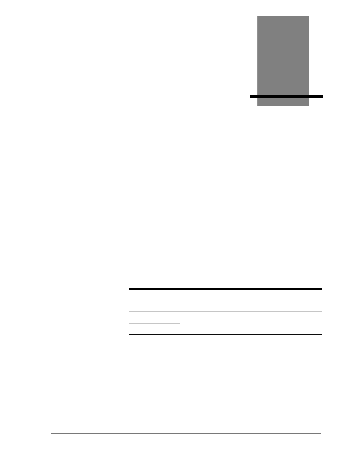
Four models are available and can be used with the following
cardiac stress testing systems:
All models feature variable speed and grade and a 20-inchwide walking surface.
Treadmill
Model
Where Used
TM55
Quinton Q-Stress Cardiac Stress System
Burdick Quest Exercise Stress System
TM65
ST55
Quinton Q-4500 Stress Test Monitor System
Quinton Q710 Stress Monitor & Resting ECG System
ST65
Page 8
1-2 Introduction Cardiac Stress Treadmills User Guide
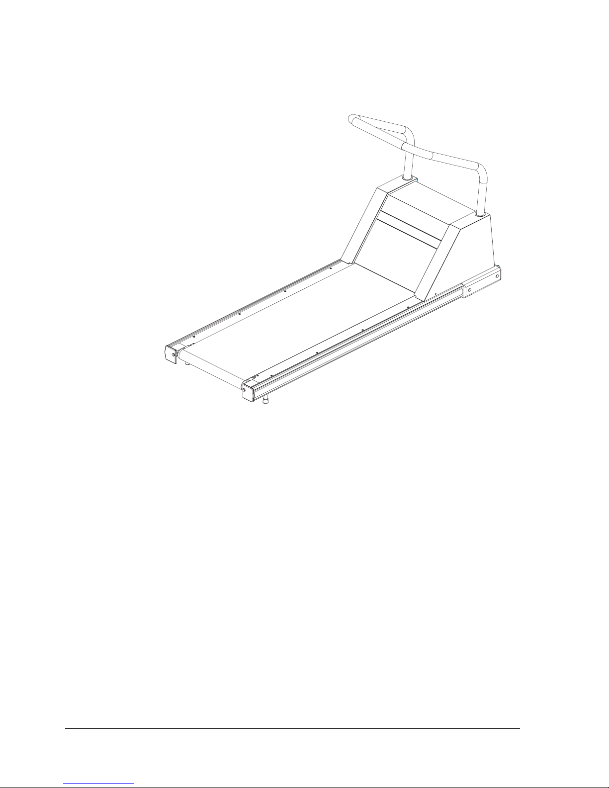
Treadmill Configuration
Controls
Power
The circuit breaker on the front of the treadmill hood controls
the power to the treadmill (see item 1 in the next drawing).
The circuit breaker must be set to
ON for the treadmill to run.
As long as the treadmill is plugged into a powered socket and
the circuit breaker is set to ON, the treadmill is receiving
power, even when the monitoring system power is turned off.
WARNING! Turn off the treadmill circuit breaker before
connecting or disconnecting the treadmill from the
power outlet.
1. Front of hood
2. Walking belt
3. Rear of treadmill
1
2
3
Page 9
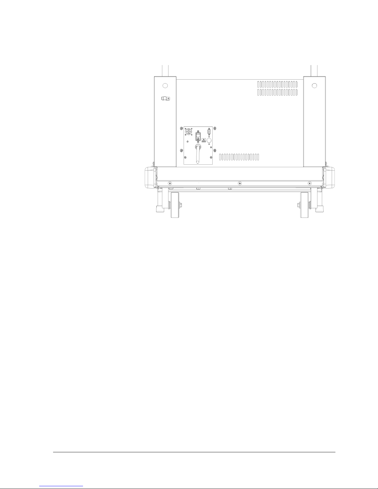
Cardiac Stress Treadmills User Guide Introduction 1-3
Hood Configuration Plate for Treadmill
Operation
Except for an optional emergency stop button, all commands,
including walking belt power, speed, grade, and protocol, are
entered from the monitoring system. All patient data will
appear on the monitoring system screen. Use the operator
manual supplied with the monitoring system for instructions
on how to control the treadmill.
As long as the treadmill is plugged into a powered socket and
the circuit breaker is set to
ON, the treadmill is receiving
power, even when the monitoring system power is turned off.
Emergency Stop Button
The treadmill may have an optional emergency stop button
located on the front handrail. When pressed, power to the belt
drive motor and the grade motor is stopped.
♦ The emergency stop button is intended only for emergency use.
You may have to restart the stress test if the emergency stop
button is pressed.
1. Circuit Breaker
2. Power cord
1
2
Page 10

1-4 Introduction Cardiac Stress Treadmills User Guide
WARNING! If your treadmill is equipped with the Emergency
Stop Button feature, the treadmill will not run unless
the emergency button cable is plugged into the
connector on the front of the hood. Once installed,
this cable should not be removed except by an
authorized technician.
Indicators
There are no visual indicators on the treadmill. All patient
responses and warnings for low power, motor overload, and
such appear on the stress test monitoring system screen.
Accessories and Options
The following are available for order:
Part No. Description
036734-002 Hand grip, Blue Vinyl
013802-003 Hand grip Blue Vinyl, Emergency Stop
032758-001 Side Handrail Kit, Short, TM55/ST55
032758-002 Side Handrail Kit, Short, TM65/ST65
032759-001 Side Handrail Kit, Long TM55/ST55
032759-002 Side Handrail Kit, Long TM65/ST65
019331-001 Low Handrail Kit
037082-xxx
Rapid Deceleration Kit (specify
language)
037080-xxx
Emergency Stop Button Kit (specify ST
or TM version)
Page 11
Cardiac Stress Treadmills User Guide Operating the Treadmill 2-1
2
Operating the Treadmill
The stress test monitor controls all treadmill operation. Please
read the following treadmill-specific information, then refer to
the operator manual supplied with your stress test monitor for
operational procedures.
Guidelines for Safe Operation
• Keep the treadmill area clear. Maintain a minimum open
space of 1.5 feet (0.5 meter) on each side and 6 feet (2
meters) at the rear.
• Before using the treadmill, verify that the correct cable
connects the treadmill to the monitoring system.
• Do not start the treadmill when someone is standing on
the belt.
• Never place chairs or other objects on treadmills.
• Do not leave a patient unattended on the treadmill.
• Patients and clinicians should secure long hair and loose
clothing before using and operating the treadmill.
Page 12

2-2 Operating the Treadmill Cardiac Stress Treadmills User Guide
• Keep speed and grade at minimum settings when patients
are getting on and off the treadmill.
• Use the optional emergency stop button only for
emergency.
Instructing the Patient
1. Before each test, describe the complete procedure to the
patient. Remind the patient to not use the handrail for
support during the exercise unless absolutely necessary.
Explain that gripping the handrail can affect the accuracy
of the test measurements. Describe how you will change
the belt speed and treadmill grade during the test.
2. Demonstrate how to get on and off the moving belt:
a. Stand next to the treadmill belt, facing the front of
the treadmill.
b. Place both hands on the handrail.
c. Step onto the side of the deck or straddle the belt.
d. (Optional) Place one foot forward on the belt and let
it move backwards, as though walking with one foot.
Repeat until comfortable.
e. Carefully step onto the belt and begin walking.
f. When able to walk unassisted, let go of the handrail.
g. While walking on the treadmill:
• Face forward; avoid looking down.
• Maintain speed by keeping a constant distance
from the handrail.
Starting the Exercise
1. Start the treadmill walking belt while the patient stands
on the side of the deck or straddles the walking belt.
Page 13
Cardiac Stress Treadmills User Guide Operating the Treadmill 2-3
WARNING! Do not start the belt while someone is on the
treadmill belt.
2. Set the speed and grade to the minimum settings.
3. Have the patient step onto the treadmill as previously
instructed.
4. Inform the patient beforehand when you are about to
change speed or grade.
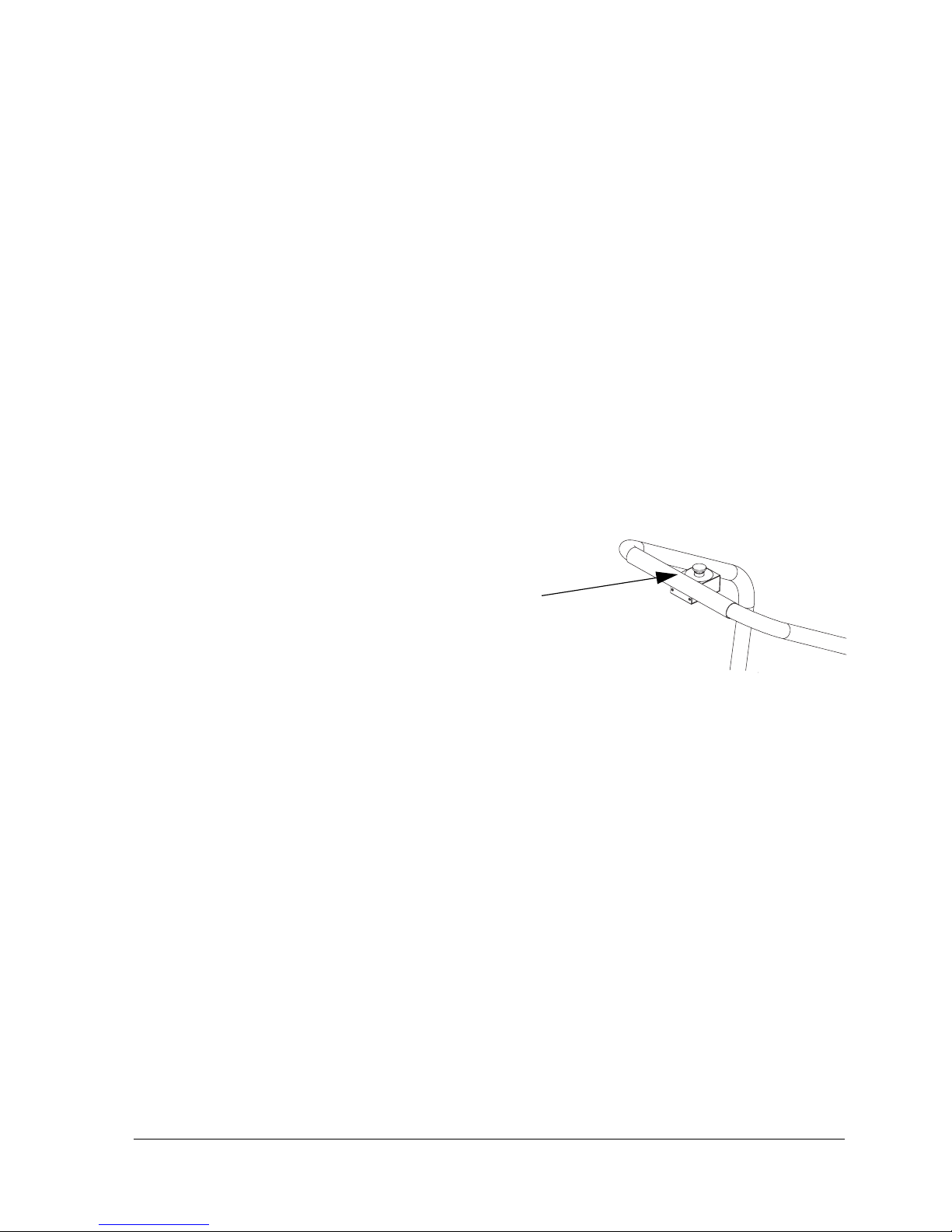
Emergency Stop Button (option)
If your treadmill is equipped with an optional emergency stop
button, pressing this button will cut power to the belt drive
motor and the grade motor, stopping the belt. The button will
lock into place and the treadmill will not run until the button
is disengaged. To unlock the button, turn it counter-clockwise.
Ending the Exercise
1. Tell the patient when the test is about to end. Decrease
the speed and grade gradually to minimum settings.
2. Before stopping the walking belt, tell the patient to grasp
the handrail for balance.
3. Stop the walking belt.
4. Tell the patient to hold the handrail and step off to the
side.
Warning! The patient may be slightly unsteady for several
seconds after stepping off the walking belt.
Emergency Stop Button
Page 14

Page 15
Cardiac Stress Treadmills User Guide Maintenance/Troubleshooting 3-1
3
Maintenance/Troubleshooting
The treadmill should be visually inspected, cleaned, and
adjusted regularly and as needed.
Daily Visual Inspection
• Inspect the treadmill power cord and walking belt for
wear.
• Check the position of the walking belt; be sure it is not
rubbing against the frame. It should be centered on the
deck within 0.25 inch of the sides; adjust if necessary.
• Check optional attachments to be sure they are fastened
securely.
• Remove potential hazards from the treadmill area.
Page 16

3-2 Maintenance/Troubleshooting Cardiac Stress Treadmills User Guide
Cleaning
Exterior
WARNING! Turn off the treadmill and unplug the power cord
from the wall outlet before cleaning.
Daily
Keep the treadmill free of dust and debris. Clean the exterior
and walking belt with a damp sponge; do not soak surfaces.
Dry all surfaces thoroughly.
Caution! Never wipe the deck beneath the belt, even when
changing the belt. Wiping can damage the wax finish.
Do not use detergents or cleaning agents on any part
of the deck.
Do not let liquid enter the interior of the treadmill. If it
does, the equipment must be inspected and tested
for safety by an approved technician before it can be
used again.
Weekly
Elevate the treadmill to maximum grade and vacuum the
floor under it to prevent excess dust and dirt from interfering
with operation.
Interior
Depending upon the treadmill environment, dust and or lint
can accumulate under the hood. Periodic internal cleaning by
an authorized technician is recommended (see Service
Manual).
Disinfection
If it is necessary to disinfect the treadmill, follow the
procedures established by your institution.
♦ Do not use liquids on the deck surface.
Page 17

Cardiac Stress Treadmills User Guide Maintenance/Troubleshooting 3-3
Adjustments
Tools Required: hex wrenches, Phillips screwdriver
Warning! Secure long hair and loose clothing before using the
treadmill or working near the treadmill walking
surface or pulleys.
Belt Tension
Adjust the belt tension whenever the belt slips or moves
unsteadily during operation:
1. Use the controls on the monitoring system to start the
treadmill at minimum speed and grade, then increase the
speed to 2.5 mph.
2. Hold onto the handrail for balance and walk heavily on
the treadmill by marching flat-footed.
a. If the belt hesitates or lags noticeably, tighten the belt
as in steps 3 and 4.
Caution! Do not use all your weight to resist the belt
movement. Too much resistance applied too long
(more than two seconds) will shut down the system.
If this should occur, recycle power to resume normal
operation.
b. Increase the speed to 4.5 mph (7.1 km/h) and jog on
the treadmill. If the belt hesitates or lags noticeably,
tighten the belt as in steps 3 and 4.
c. Increase the speed to 6.5 mph (10.3 km/h) and run on
the treadmill. If the belt hesitates or lags noticeably,
tighten the belt as in steps 3 and 4.
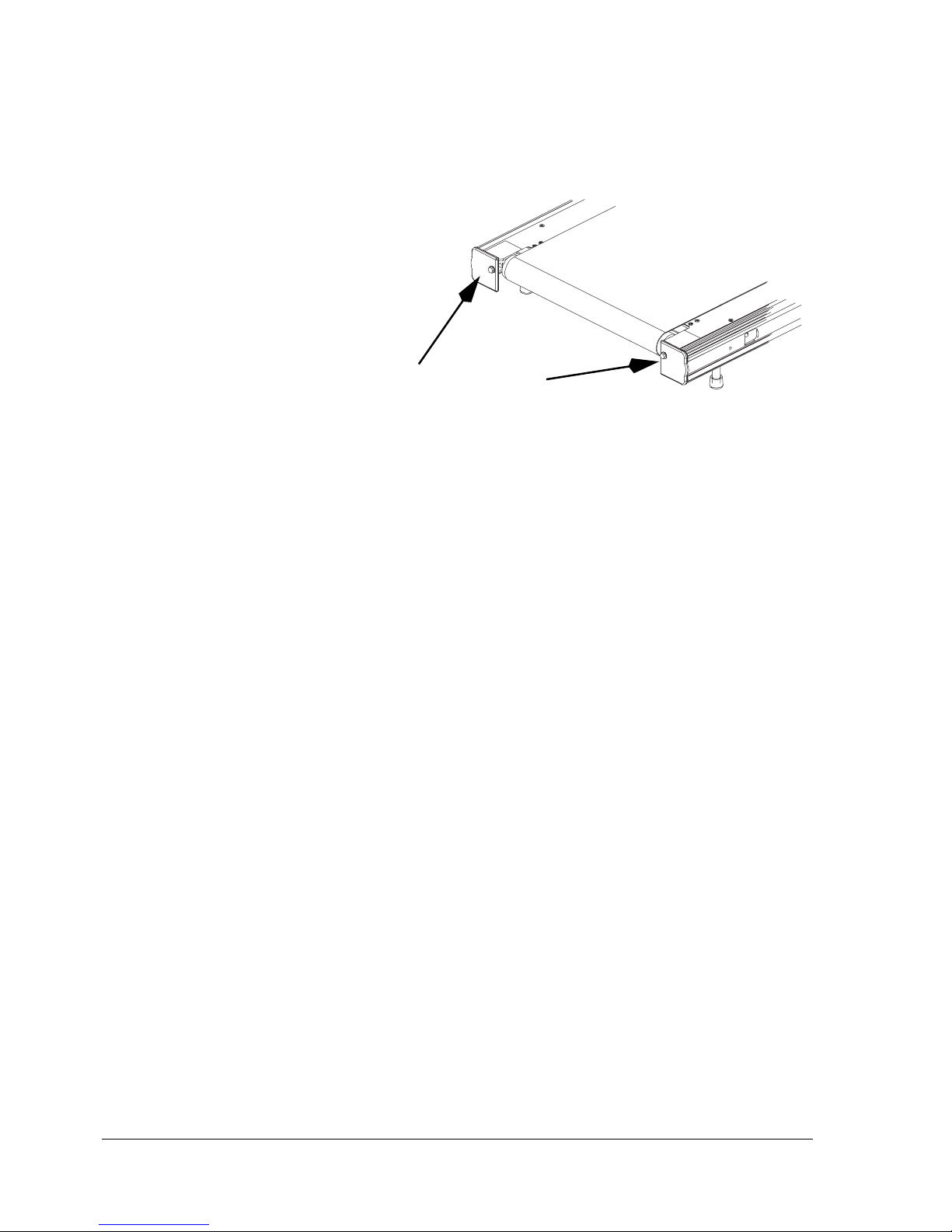
3. Locate the two adjustment bolts at the rear of the
treadmill
Page 18
3-4 Maintenance/Troubleshooting Cardiac Stress Treadmills User Guide
4. Turn both adjustment bolts clockwise 1/4 turn. Test the
belt tension as in Step 2. Repeat if necessary until the belt
runs smoothly without slipping. If more than three
adjustments are necessary, call an authorized technician.
Caution! Do not overtighten the walking belt. Overtightening
can damage the belt and rollers. Do not torque
adjustment screws beyond 80 in/lb (9 Nm) maximum.
5. Stop the treadmill.
6. Check the position of the rear roller guards and adjust if
necessary (see “Rear Roller Guards” on page 3-5).
Belt Tracking
Perform this procedure whenever the belt moves to one side or
the other.
WARNING! Stay off the belt when adjusting the tracking. Do not
touch or grab the walking belt while it is moving.
1. Use the controls on the monitoring system to start the
treadmill at minimum speed and grade.
2. Increase speed to 6 mph (9.5 km/h) and make the
following adjustment (See Belt Tension for the location
of the bolts):
a. If the belt moves to the right, rotate the right tension
bolt clockwise 1/4 turn.
b. If the belt moves to the left, rotate the left tension
bolt clockwise 1/4 turn.
Adjustment bolts
Page 19
Cardiac Stress Treadmills User Guide Maintenance/Troubleshooting 3-5
3. After making an initial adjustment, run the treadmill for
several minutes and observe how the belt tracks;
adjustments to belt tracking take several minutes to
become apparent. If the belt continues to move off center,
adjust accordingly until it is properly centered.
If more than three adjustments are necessary, call an
authorized technician.
Caution! Do not overtighten the walking belt. Overtightening
can damage the belt and rollers. Do not torque
adjustment screws beyond 80 in/lb. (9N/m)
maximum.
4. Stop the treadmill.
5. Check the position of the rear roller guards and adjust, if
necessary (see “Rear Roller Guards” below).
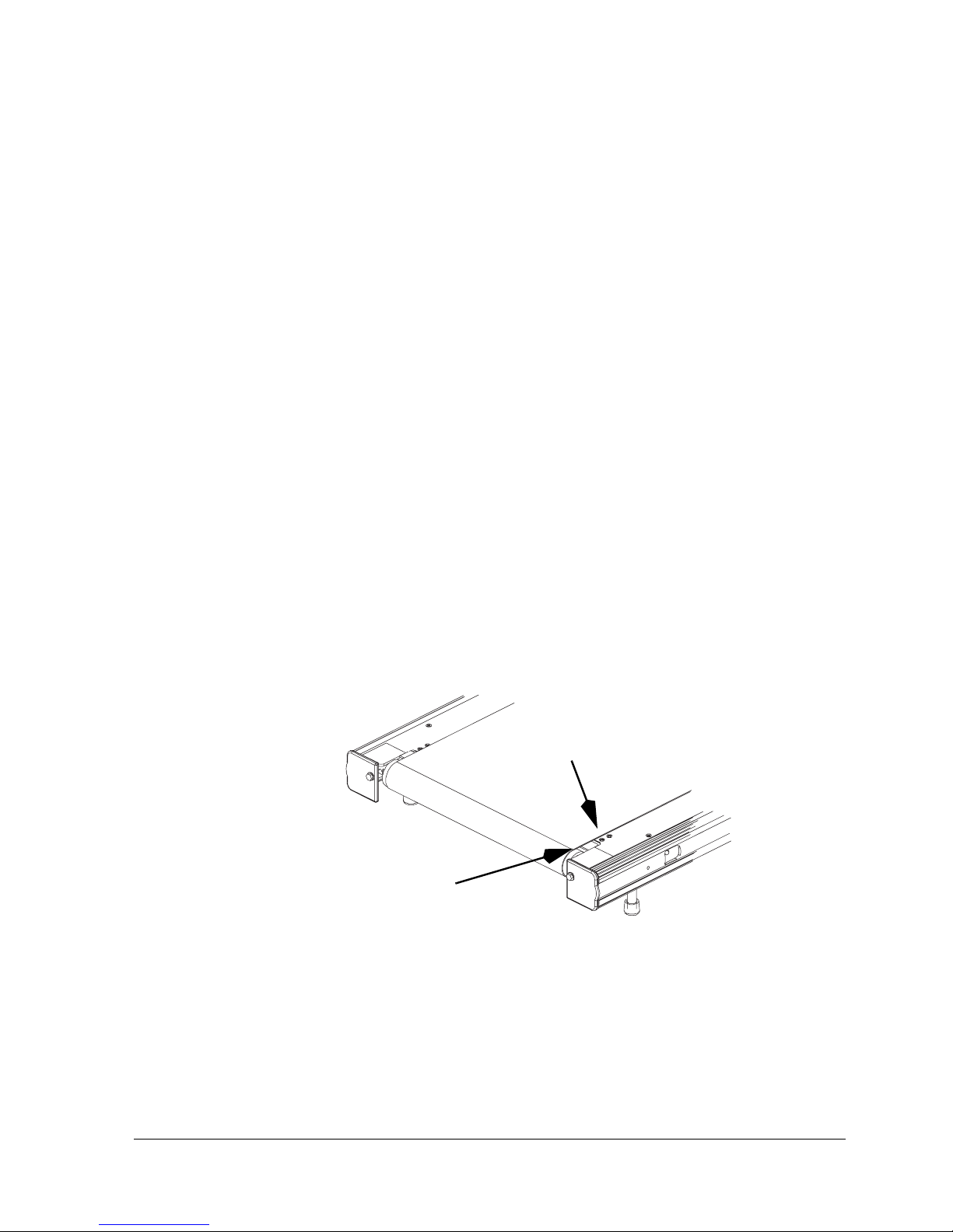
Rear Roller Guards
Check the position of the rear roller guards each time you
readjust the belt tracking or the belt tension. The roller guards
are located at the rear of the treadmill between the rear roller
and the deck (see following figure).
Adjust the guards when the gap between the roller and the
guard exceeds 3/8 of an inch (or 0.375 inch) (9.5 mm).
1. Disconnect the treadmill power cord from the power
source.
2. Loosen, but do not remove, the two screws attaching the
rear roller guard to the deck (hold the nuts on the
underside with your finger).
Adjustment Screws
Roller Guard
Page 20

3-6 Maintenance/Troubleshooting Cardiac Stress Treadmills User Guide
3. Slide the rear roller guard towards the rear roller until the
gap between the two is approximately 0.1 inch (2.5 mm
or the thickness of two quarters).
4. Tighten the mounting screws loosened in Step 2.
5. Connect the power cord.
Warning! Do not permit anyone to stand on the treadmill belt
when it is started.
6. Use the controls on the monitoring system to start the
treadmill belt. If there is a scraping noise by the rear
roller guards, redo steps 1 through 6.
Electrical Testing
Electrical testing is to be done by the facility’s biomedical
department as required. Check the leakage current of the
treadmill periodically—at least every nine months—to be sure
it does not exceed local or provincial standards.
Moving and Storing the treadmill
Warning! Moving the treadmill requires two people.
1. If you are using a Quinton Q-Stress system, remove the
Q-Stress preamp if it is attached to the handrail.
2. Set the treadmill to 3 to 5% grade.
3. To avoid electric shock, turn off the treadmill circuit
breaker and the monitoring system, then remove the
power cord from the power source.
Warning! As long as the treadmill is plugged into a powered
outlet and the treadmill circuit breaker is set to ON,
the treadmill is receiving power, even when the
monitoring system is turned off. Do not place hands
beneath the treadmill while it is plugged in.
4. Together, lift the rear of the treadmill, then roll it to the
new site using the wheels on the front of the treadmill.
Page 21

Cardiac Stress Treadmills User Guide Maintenance/Troubleshooting 3-7
When storing for prolonged periods, cover the treadmill with
a dust cover. Do not store in damp areas.
WARNING! Do not store the treadmill on its end as it could fall on
someone.
Re-use
Before using the treadmill again after moving or storage,
check the power cord and all attachments to be sure they are
undamaged and securely connected, then test the system for
proper operation.
Troubleshooting
If the walking belt does not run, check the monitoring system
for an error code. Record the code, if present, then call an
authorized technician. If no error message is present, recycle
the power by turning the monitoring system power off and on
again; this may eliminate the fault. If not, check the interface
cables for proper connection.
If problems persist, refer to the Troubleshooting Guide that
follows. Problems beyond the scope of this table can require
service assistance to isolate and correct. Contact an
authorized technician or call 800-426-0337.
Warning! Do not remove the treadmill hood: Dangerous
voltages are present. There are no operatorserviceable components.
Caution! Servicing should be done only by an authorized
technician who should consult the service manual
before attempting any in-depth troubleshooting.
Page 22

3-8 Maintenance/Troubleshooting Cardiac Stress Treadmills User Guide
Troubleshooting Guide
Problem Possible Cause Remedy
Treadmill will not run Treadmill or monitoring
system power cord is not
plugged in.
Plug in power cords.
Interface cable disconnected
or damaged
Plug in and secure interface cable.
Replace if damaged.
Monitoring system power off. Turn on power. Check AC power, if
necessary.
Circuit breaker on treadmill
hood reads OFF.
Set the circuit breaker switch on the
treadmill to ON.
1. Start key not selected.
2. Not in proper menu.
Press proper key on monitoring system
control panel. Consult stress test
system user guide.
No power at outlet Check building circuit breaker.
Voltage below nominal Provide dedicated line for treadmill.
Emergency Stop button has
been unplugged.
Plug into connector on front of hood.
Emergency Stop button
activated.
Turn emergency stop button counterclockwise to deactivate.
Internal problem. Service required. Contact an
authorized technician.
Walking belt too far
left or right
Improper belt tracking. Adjust tracking (see “Belt Tracking” on
page 3-4). If problem persists, contact
an authorized technician.
Walking belt slips,
but front roller turns.
Improper belt tension Adjust belt tension (see “Belt Tension”
on page 3-3). If problem persists, contact an authorized technician.
Walking belt
hesitates; adjusting
walking belt tension
is ineffective
Internal drive belt slipping. Service required. Contact an
authorized technician.
Treadmill will not
change grade.
Excess weight on treadmill. See Appendix B for maximum load.
Internal problem. Service required. Contact an
authorized technician.
Circuit breaker trips
during normal
operation.
Power fault. Service required. Contact an
authorized technician.
Error messages on
stress test monitor
Refer to monitoring system
user guide.
Refer to monitoring system user guide.
Internal problem Service required. Contact an
authorized technician.
Page 23
Cardiac Stress Treadmills User Guide Safety Requirements A-1
A
Safety Requirements
Warnings and Cautions
• Read this manual in full before operating the treadmill.
• Before each use of this equipment, check the power
receptacle for signs of damage. Do not operate the
equipment if the integrity of these items is in question.
• Be sure the connection for the optional Emergency Off
switch is secure. Test the switch to verify proper
operation. Do not operate the equipment if the integrity
of these items is in question.
• Regularly inspect cables and treadmill belts for wear or
damage. Do not operate the equipment if the integrity of
these items is in question.
• When connecting auxiliary equipment approved for use
with the monitoring system, be certain the summation
leakage current does not exceed local or provincial
standards.
Page 24

A-2 Safety Requirements Cardiac Stress Treadmills User Guide
• The treadmill must be on an appropriate, dedicated
electrical circuit with a power rating that meets the
electrical specification on the treadmill serial number
label. Nothing else should be connected to the circuit.
• To avoid potential safety and electrical problems, use
parts and accessories that meet specifications as noted in
this user guide and the user guide for your stress monitor.
• Use of accessories or cables other than those specified,
with the exception of accessories or cables sold by
Quinton Cardiology, Inc. as replacement parts for
internal components, may result in increased emissions
or decreased immunity of the treadmill.
• This equipment is classified Class I, Type B, ordinary
equipment, not protected against fluid ingress. It is rated
for continuous operation.
• The Cardiac Stress Treadmill needs special precautions
regarding EMC and needs to be installed and put into
service according to the guidelines of the EMC
declaration tables.
• Portable and mobile RF communications equipment may
affect the Cardiac Stress Treadmill and the recommended
separation distances in the EMC declaration tables
should be observed.
• The Cardiac Stress Treadmill should not be used adjacent
to or stacked with other equipment. If adjacent or stacked
use is necessary, the Cardiac Stress Treadmill should be
observed to verify normal operation in the configuration
in which it will be used.
• Do not operate this equipment in the presence of
flammable anesthetic mixtures.
• Increased risk due to leakage current can result if this
equipment is not grounded properly.
Page 25

Cardiac Stress Treadmills User Guide Safety Requirements A-3
• Failure to follow these guidelines can produce a serious
or possibly fatal electrical shock hazard. Consult a
qualified electrician as required.
• Do not start the treadmill when someone is standing on
the belt.
• Keep speed and grade at the lowest settings when getting
on and off the treadmill belt.
• Never place chairs or other objects on treadmills.
• Keep the area underneath and around the treadmill clear.
Make sure cables are clear of the treadmill.
• Be aware of a moving treadmill belt.
• Allow sufficient room for patients to maneuver around
the system and to safely mount and dismount the
treadmill.
• Ensure the patient understands the proper treadmill
mount and dismount procedure.
• Patient should straddle the treadmill belt or stand on the
deck’s edge at start up.
• The patient should always face the front of the treadmill
when stepping on or off the belt. Do not step onto the belt
while facing the side of the treadmill.
• At the end of the test, patient should hold the handrail
and step off to the side of the treadmill.
• Properly train new staff.
• If your treadmill is equipped with the rapid deceleration
profile, it is specifically designed to come to a rapid stop.
This feature requires that attendant(s) are available to
support and assist the patient user. Attendants MUST
be
in a position to support and assist the patient when the
belt stops.
Page 26

A-4 Safety Requirements Cardiac Stress Treadmills User Guide
EMC Declaration Tables
Guidance and Manufacturer's Declaration - Electromagnetic Emissions
The Cardiac Stress Treadmills are intended for use in the electromagnetic environment specified
below. The customer or the user of the Cardiac Stress Treadmills should assure that they are used
in such an environment.
Emissions test Compliance Electromagnetic environment - guidance
RF emissions
CISPR 11
Group 1
The Cardiac Stress Treadmills use RF energy only for
its internal function. Therefore, its RF emissions are
very low and are not likely to cause any interference
in nearby electronic equipment.
RF emissions
CISPR 11
Class A
The Cardiac Stress Treadmills are suitable for use in
all establishments other than domestic and those
directly connected to the public low-voltage power
supply network that supplies buildings used for
domestic purposes.
Harmonic
emissions
IEC 61000-3-2
Class A
Voltage fluctuations/
flicker emissions
IEC 61000-3-3
Complies
NOTE Tests verified with shielded input/output cables only.
Page 27

Cardiac Stress Treadmills User Guide Safety Requirements A-5
Guidance and Manufacturer's Declaration - Electromagnetic Immunity
The Cardiac Stress Treadmills are intended for use in the electromagnetic environment specified below.
The customer or the user of the Cardiac Stress Treadmills should assure that they are used in such an
environment.
Immunity test
IEC 60601 test
level
Compliance Level
Electromagnetic environment -
guidance
Electrostatic
discharge (ESD)
IEC 61000-4-2
+ 6kV contact
+ 8 kV air
+ 6kV contact
+ 8 kV air
Floors should be wood, concrete or
ceramic tile. If floors are covered
with synthetic material, the relative
humidity should be at least 30%.
Electrical fast
transient/burst
IEC 61000-4-4
+2 kV for power
supply lines
+1 kV for input/
output lines
+2 kV for power
supply lines
+1 kV for input/
output lines
Mains power quality should be that
of a typical commercial or hospital
environment
Surge
IEC 61000-4-5
+ 1 kV differential
mode
+2 kV common
mode
+ 1 kV differential
mode
+2 kV common
mode
Mains power quality should be that
of a typical commercial or hospital
environment
Voltage dips, short
interruptions and
voltage variations
on power supply
input lines
IEC 61000-4-11
<5% U
T
(>95% dip in UT) for
0.5 cycle
<40% U
T
(>60% dip in UT) for
5 cycle
<70% U
T
(>30% dip in UT)
for25 cycle
<5% U
T
(>95% dip in UT) for
5 sec
<5% U
T
(>95% dip in UT) for
0.5 cycle
<40% U
T
(>60% dip in UT) for
5 cycle
<70% U
T
(>30% dip in UT)
for25 cycle
<5% U
T
(>95% dip in UT) for
5 sec
Mains power quality should be that
of a typical commercial or hospital
environment. If the user of the ST/
TM55 or ST/TM65 requires
continued operation during power
mains interruptions, it is
recommended that the ST/TM55 or
ST/TM65 be powered from an
uninterruptible power supply or a
battery.
Power frequency
(50/60 Hz)
Magnetic field
IEC 61000-4-8
3 A/m 3 A/m
Power frequency magnetic fields
should be at levels characteristic of a
typical location in a typical
commercial or hospital environment
NOTE 1: UT is the a.c. mains voltage prior to application of the test level.
NOTE 2: Tests verified with shielded input/output cables only.
Page 28
A-6 Safety Requirements Cardiac Stress Treadmills User Guide
Guidance and Manufacturer's Declaration - Electromagnetic Immunity
The Cardiac Stress Treadmills are intended for use in the electromagnetic environment specified below. The
customer or the user of the Cardiac Stress Treadmills should assure that they are used in such an
environment.
Immunity test
IEC 60601 test
level
Compliance Level
Electromagnetic environment -
guidance
Conducted RF
IEC 61000-4-6
3 Vrms
150 kHz to 80 MHz 3 V
Portable and mobile RF communications
equipment should be used no closer to
any part of the ST/TM55 or ST/TM65,
including cables, than the recommended
separation distance calculated from the
equation applicable to the frequency of the
transmitter.
Recommended separation distance
Radiated RF
IEC 61000-4-3
3 V/m
80 MHz to 2.5 GHz
3 V/m 80 MHz to 800 MHz
800 MHz to 2.5 GHz
where P is the maximum output power
rating of the transmitter in watts (W)
according to the transmitter manufacturer
and d is the recommended separation
distance in meters (m).
Field strengths from fixed RF transmitters,
as determined by an electromagnetic site
survey
a
, should be less than the
compliance level in each frequency range
b
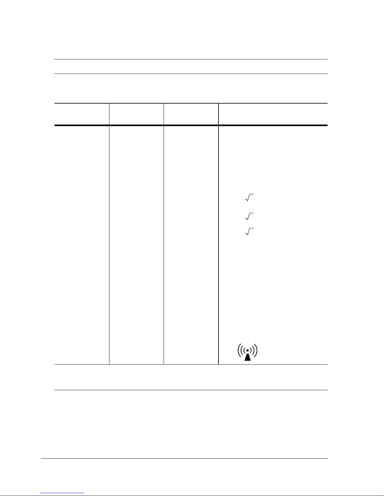
Interference may occur in the vicinity of
equipment marked with the following
symbol:
NOTE 1: At 80 MHz and 800 MHz, the higher frequency range applies.
NOTE 2: These guidelines may not apply in all situations. Electromagnetic propagation is affected by absorption and reflection from
structures, objects and people.
NOTE 3: Tests were verified with shielded input/output cables only.
a.Field strengths from fixed transmitters, such as base stations for radio (cellular/cordless) telephones and land mobile radios,
amateur radio, AM and FM radio broadcast and TV broadcast cannot be predicted theoretically with accuracy. To assess the electromagnetic environment due to fixed RF transmitters, an electromagnetic site survey should be considered. If the measured field
strength in the location in which the ST/TM55 or ST/TM65 is used exceeds the applicable RF compliance level above, the ST/
TM55 or ST/TM65 should be observed to verify normal operation. If abnormal performance is observed, additional measures may
be necessary, such as reorienting or relocating the ST/TM55 or ST/TM65.
b.Over the frequency range 150 kHz to 80 MHz, field strengths should be less than 3 V/m.
d 1.2 P=
d 1.2 P=
d 2.3 P=
Page 29
Cardiac Stress Treadmills User Guide Safety Requirements A-7
)
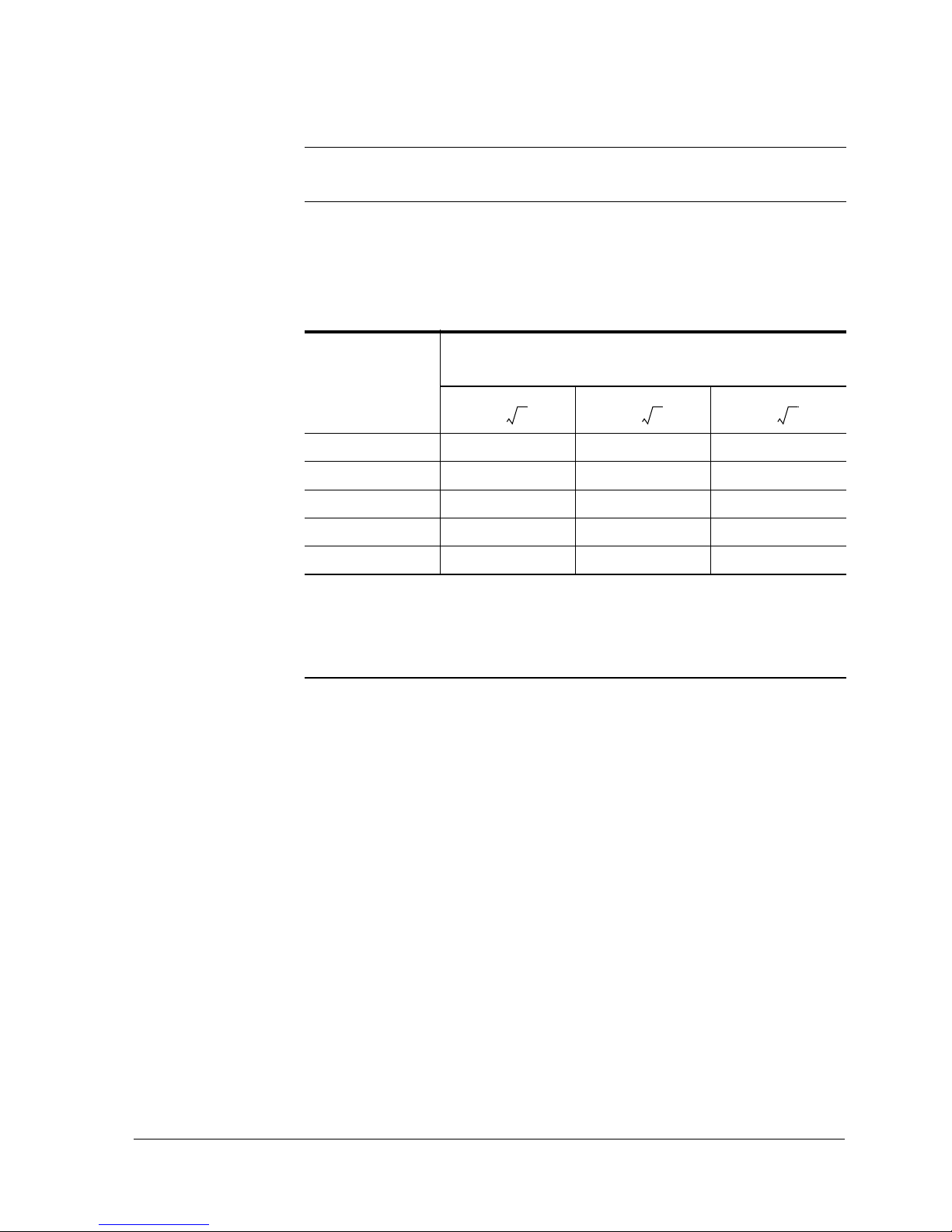
Recommended Separation Distances Between Portable and Mobile RF
Communications Equipment and the Cardiac Stress Treadmills
The Cardiac Stress Treadmills are intended for use in an electromagnetic environment
in which radiated RF disturbances are controlled. The customer or the user of the
Cardiac Stress Treadmills can help prevent electromagnetic interference by
maintaining a minimum distance between portable and mobile RF communications
equipment (transmitters) and the Cardiac Stress Treadmills as recommended below,
according to the maximum output power of the communications equipment.
Rated maximum
output power of
transmitter
W
Separation distance according to frequency of transmitter
m
150 kHz to 80 MHz 80 MHz to 800 MHz 800 MHz to 2.5 GHz
0.01 0.12 0.12 0.23
0.1 0.38 0.38 0.73
1 1.2 1.2 2.3
10 3.8 3.8 7.3
100121223
For transmitters rated at a maximum output power not listed above, the recommended separation distance d in
meters (m) can be estimated using the equation applicable to the frequency of the transmitter, where P is the
maximum output power rating of the transmitter in watts (W) according to the transmitter manufacturer.
NOTE 1 At 80 MHz and 800 MHz, the higher frequency range applies.
NOTE 2 These guidelines may not apply in all situations. Electromagnetic propagation is affected by
absorption and reflection from structures, objects and people.
NOTE 3 Tests were verified with shielded input/output cables only.
d 1.2 P= d 1.2 P= d 2.3 P=
Page 30

Page 31
Cardiac Stress Treadmills User Guide Specifications B-1
B
Specifications
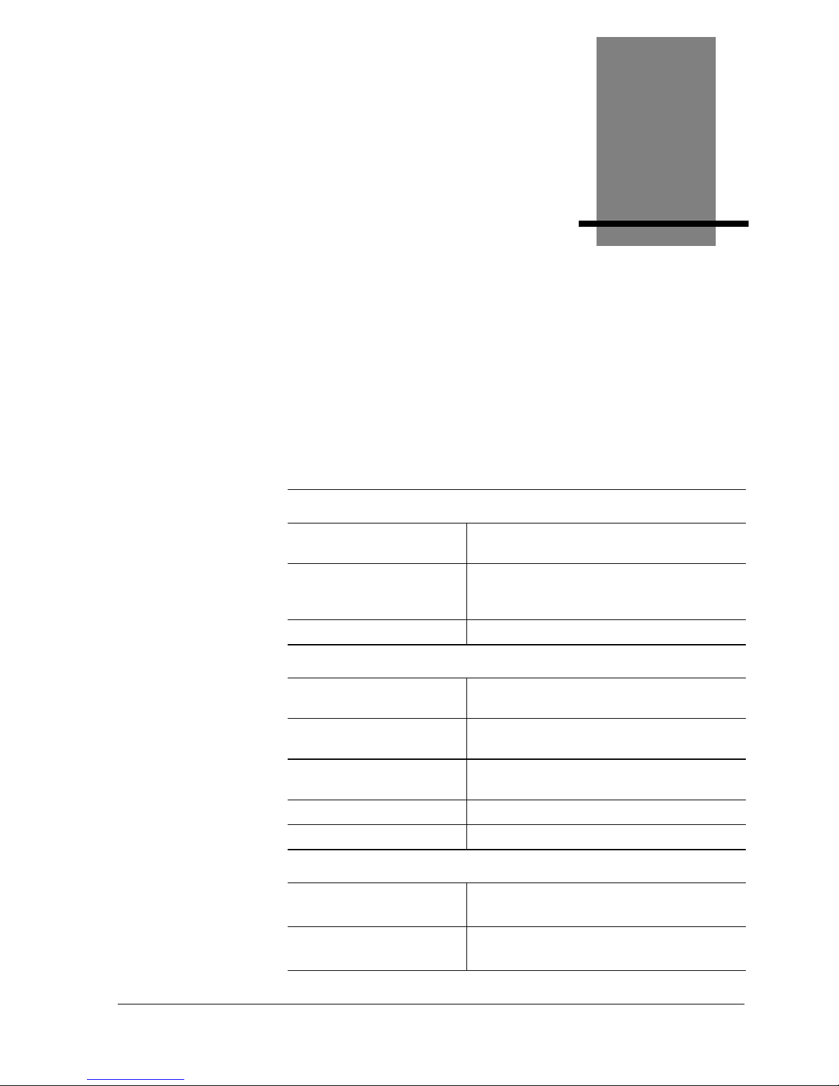
Cardiac Stress Treadmills
Performance
Maximum Rated Load 500 lb (227.3 kg) (with restrictions -- see
Speed Vs. Weight graph next page)
Belt Speed Range ± 0.2
mph (continuously
adjustable)
0.8 to 9.6 mph (1.3 to 15.4 km/h)
Grade Range ± 0.5% 0 to 25%
Physical
Weight ST/TM55: 352 lb (160 kg)
ST/TM65: 375 lb (170 kg)
Nominal Walking Surface ST/TM55: 20 x 55 in. (51 x 140 cm)
ST/TM65: 20 x 65 in. (51 x 165 cm)
Treadmill Area ST/TM55: 29.9 x 80.2 in. (76 x 204 cm)
ST/TM65: 29.9 x 90.2 in. (76 x 229 cm)
Walking Surface Height 7.0 in. (18 cm) from floor
Handrail Height 47.2 in. (120 cm) from floor
Environmental
Temperature Operating: 50 to 104 °F (10 to 40 °C)
Storage: -40 to 158 °F (-40 to 70 °C)
Humidity (noncondensing)
Operating: 15 to 95% relative
Storage: 5 to 95% relative
Page 32
B-2 Specifications Cardiac Stress Treadmills User Guide
Power Requirements
Listed below are the power requirements for your treadmill
* The nominal voltage range is listed on the serial number
name plate, which can be found on the hood under the
circuit breaker switch.
**Full-load current is computed as described in section
430-24 of the National Electrical Code.
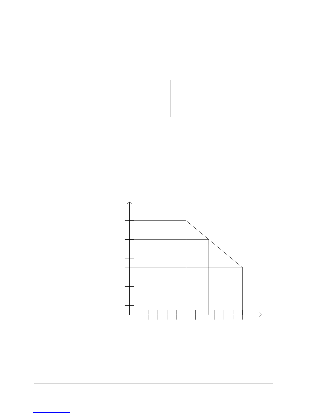
Speed Vs. Weight Range
Nominal Voltage Range
(min - max) / Hertz*
Current Draw
(Amps)
Min. Branch Circuit
Amps
100-120 V, 50/60 Hz 20** 20
200-240 V, 50/60 Hz 10** 10
100
200
300
400
500
1.6 9.68.06.44.83.2
User
Weight
Pounds
Speed (mph)
Performance Envelope 115V or 230V Operation
250
Pounds
6.7 mph
4.8 mph
Page 33
Cardiac Stress Treadmills User Guide Specifications B-3
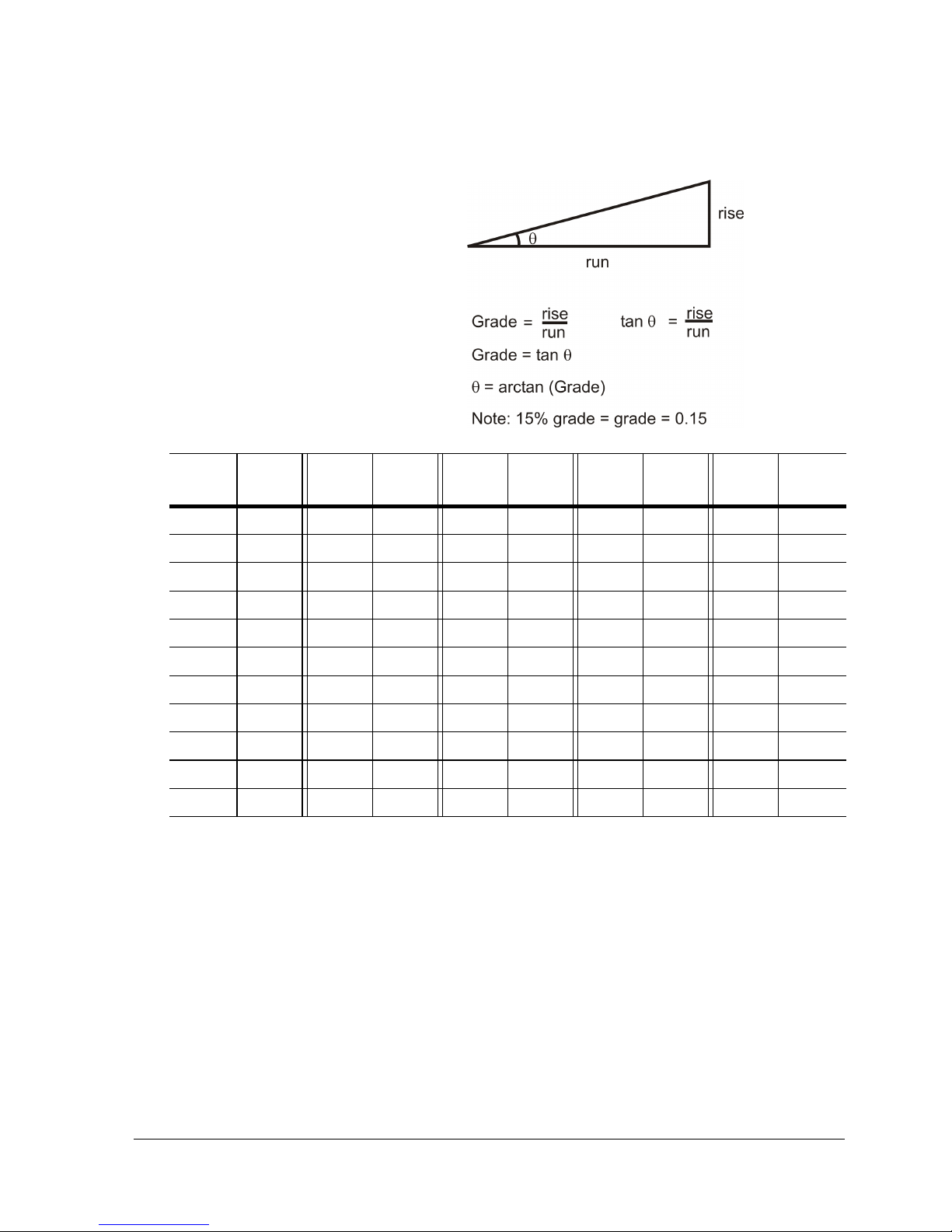
% Grade vs Angle Relationship
Grade
(%)
Angle
(°)
Grade
(%)
Angle
(°)
Grade
(%)
Angle
(°)
Grade
(%)
Angle
(°)
Grade
(%)
Angle
(°)
0.0 0.005.0 2.8610.05.7115.08.5320.011.31
0.5 0.295.5 3.1510.55.9915.58.8120.511.59
1.0 0.57 6.0 3.43 11.0 6.28 16.0 9.09 21.0 11.86
1.5 0.86 6.5 3.72 11.5 6.56 16.5 9.37 21.5 12.13
2.0 1.157.0 4.0012.06.8417.09.6522.012.41
2.5 1.437.5 4.2912.57.1317.59.9322.512.68
3.0 1.72 8.0 4.57 13.0 7.41 18.0 10.20 23.0 12.95
3.5 2.00 8.5 4.86 13.5 7.69 18.5 10.48 23.5 13.22
4.0 2.29 9.0 5.14 14.0 7.97 19.0 10.76 24.0 13.50
4.5 2.58 9.5 5.43 14.5 8.25 19.5 11.03 24.5 13.77
5.0 2.86 10.0 5.71 15.0 8.53 20.0 11.31 25.0 14.04
Page 34

Page 35
Cardiac Stress Treadmills User Guide Receiving and Installation C-1
C
Receiving and Installation
Receiving
When the carrier delivers your order, verify that the number
of items received equals the number listed on the freight bill
or express receipt.
Inspect the containers for damage. Itemize discrepancies and
damage on the waybill and have the agent sign it. Failure to
describe external evidence of loss adequately may result in
the carrier refusing to honor your claim. Do not discard the
packing materials until you have verified physical condition
and proper operation.
Installation Notice
The treadmill and controller must be installed correctly
before being used. We recommend that you contact your
treadmill dealer or representative when your equipment
arrives. The representative will help unpack, install, and
demonstrate it, to ensure that:
• equipment is free from shipping damage.
Page 36

C-2 Receiving and Installation Cardiac Stress Treadmills User Guide
• the treadmill is connected correctly to the appropriate AC
power source.
• installation and operation are in accordance with
standards stated in this manual.
Incorrect installation by unauthorized personnel can lead to
equipment damage and may void the warranty.
Warning! The treadmill must be on a dedicated branch circuit.
No other device should be connected to that circuit.
Excessive risk current (leakage) can result if the
equipment is not properly grounded.
Failure to follow these guidelines will produce a
serious or possibly fatal electrical shock hazard.
Consult a qualified electrician as required.
Site Requirements
The treadmill requires a dedicated AC power line (refer to
“Power Requirements” on page B-2). To ensure electrical
safety, the treadmill is equipped with a three-wire power cord
and three-pronged plug. To maintain ground reliability, the
plug must be connected to an equivalent receptacle.
Caution! The treadmill is designed to operate in a typical
clinical environment with adequate heat dissipation
(1850 Watts maximum).
Place the treadmill on a flat surface, free of moisture and
debris. Maintain a minimum clearance of 1.5 feet (0.5 m) on
each side and 6 feet at the rear.
If the preamp for the Q-Stress system is to be attached to the
handrail, maintain a clearance of 1.5 feet (0.5 m) at the front
of the treadmill.
Page 37
Cardiac Stress Treadmills User Guide Receiving and Installation C-3
Installation
If you choose to install your treadmill without the assistance
of your representative, follow the procedure given below:
Tools
• hex wrench (supplied in kit)
Procedure
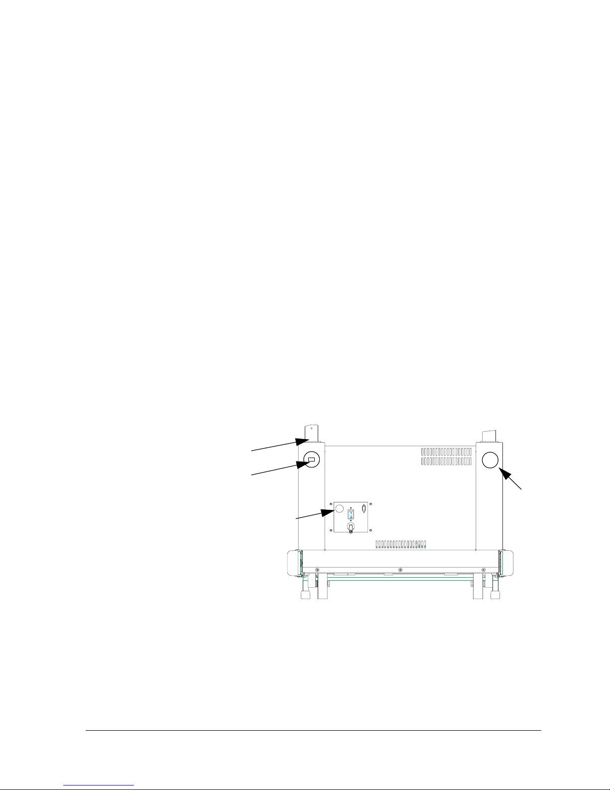
1. Ensure that the handrail gaskets have been placed in their
proper location (see drawing below).
2. Insert the front handrail into the holes on each side of the
hood.
3. Use the two hex-head socket screws recessed within the
front of the hood to secure the handrail:
a. Using the hex wrench supplied in the ship kit, turn
the socket screws clockwise.
b. Cover the screws with the caps supplied in the ship
kit.
4. Plug the cable for the optional Emergency Stop Button, if
present, into the connector on the front of the hood
(reference figure above).
♦ If the optional Emergency Stop Button is present, it must remain
connected and secured at all times. It should be disconnected
only by an authorized technician.
Socket
Screw
Cap i
n
Handrail
Gasket
Emergency Stop
Switch Connector
(optional)
Place
Page 38

C-4 Receiving and Installation Cardiac Stress Treadmills User Guide
5. (High Voltage units only) Plug the female end of the
power cord into the connector on the front of the
treadmill hood. Be sure the plug is connected securely,
then tighten the clamp using the hex wrench provided.
6. If you want to attach the Q-Stress preamp to the handrail,
follow the installation instructions included with the
preamp.
Connecting to the Monitoring System
1. Be sure the treadmill and the monitoring system are
disconnected from the power source.
2. Inspect the monitoring system interface cable connector,
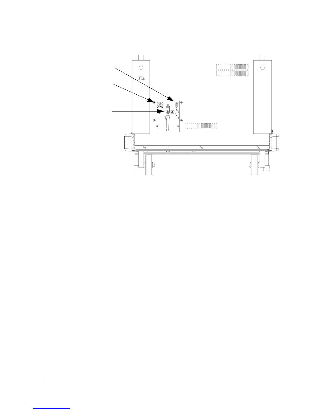
located on the front of the hood (see figure below). If it
appears damaged, contact an authorized technician
before continuing this installation.
If the connector is undamaged, plug the male end of the
monitoring system interface cable into the connector.
Tighten the connector thumb screws until finger tight.
3. Plug the female end into the treadmill connector on the
back panel of the monitoring system.
4. Verify that the outlet voltage matches the voltage on the
nameplate located on the front of the treadmill hood. If
the voltage is adequate, plug in the power cord. Do not
use this outlet if the voltage is not adequate.
Page 39
Cardiac Stress Treadmills User Guide Receiving and Installation C-5
5. Check the circuit breaker switch on the treadmill hood to
be sure it is set to ON.
6. Test the treadmill as described below by using the
controls on the monitoring system.
Testing the Treadmill
Warning! DO NOT permit anyone to stand on the treadmill
when it is started.
1. Connect the treadmill power cord to the correct power
outlet. Turn on treadmill power.
2. Start the walking belt from the monitoring system: the
treadmill starts running immediately at low speed.
3. Set the treadmill to minimum speed and zero grade and
confirm that the treadmill meets these values.
4. Set the treadmill to maximum speed and confirm that the
treadmill meets that value.
5. Set the treadmill to maximum grade and confirm that the
treadmill meets that value.
6. Let the treadmill run for at least 15 minutes.
Emergency Stop
(optional)
Circuit Breaker
Switch
Monitoring System
Interface Cable
Connector
Switch Connector
Page 40

C-6 Receiving and Installation Cardiac Stress Treadmills User Guide
a. Watch the walking belt carefully to ensure that it
does not drift left or right. Adjust if necessary using
the adjustment procedures in Chapter 3.
b. Listen for unusual noises, such as squeals or squeaks.
The treadmill should run quietly.
c. Reduce speed and grade until the treadmill belt is
moving at a reasonable speed for walking.
d. Walk on the moving belt and verify proper operation
at representative speeds and grades. If the walking
belt slips, but the front roller turns, adjust the
walking belt tension.
7. When the test is finished:
a. Set the treadmill to zero grade.
b. Stop the walking belt.
c. Turn off the monitoring system.
If your treadmill is not running smoothly, contact an
authorized technician before using it.
Page 41
Cardiac Stress Treadmills User Guide Glossary D-1
D
Glossary
Controller
Press-button panel that lets the user control the
treadmill and view exercise progress.
Deck
Treadmill surface under walking belt.
Grade
Incline, or slope, of the treadmill deck
measured in percent grade.
Monitoring
System
A device that receives ECG signals from a
patient and displays and/or records them for
review. Used with cardiac stress treadmills for
exercise testing.
Protocol
The specific treadmill workload sequence used
for a particular stress test.
Roller Guard
Metal plate at the rear of the treadmill deck,
designed to prevent people from placing fingers
between the walking belt and rear roller.
Stress Test
A procedure used to test cardiovascular and
pulmonary response. Consists of a patient
performing controlled exercise while heart and/
or lung activity is measured with precision
instrumentation. Also called a treadmill
exercise test or exercise tolerance test (ETT).
Track
The path that the treadmill belt follows.
Walking Belt
Walking surface of the treadmill—moves
according to the speed set on the controller.
Page 42

Page 43
Cardiac Stress Treadmills User Guide Symbol Definitions E-1
E
Symbol Definitions
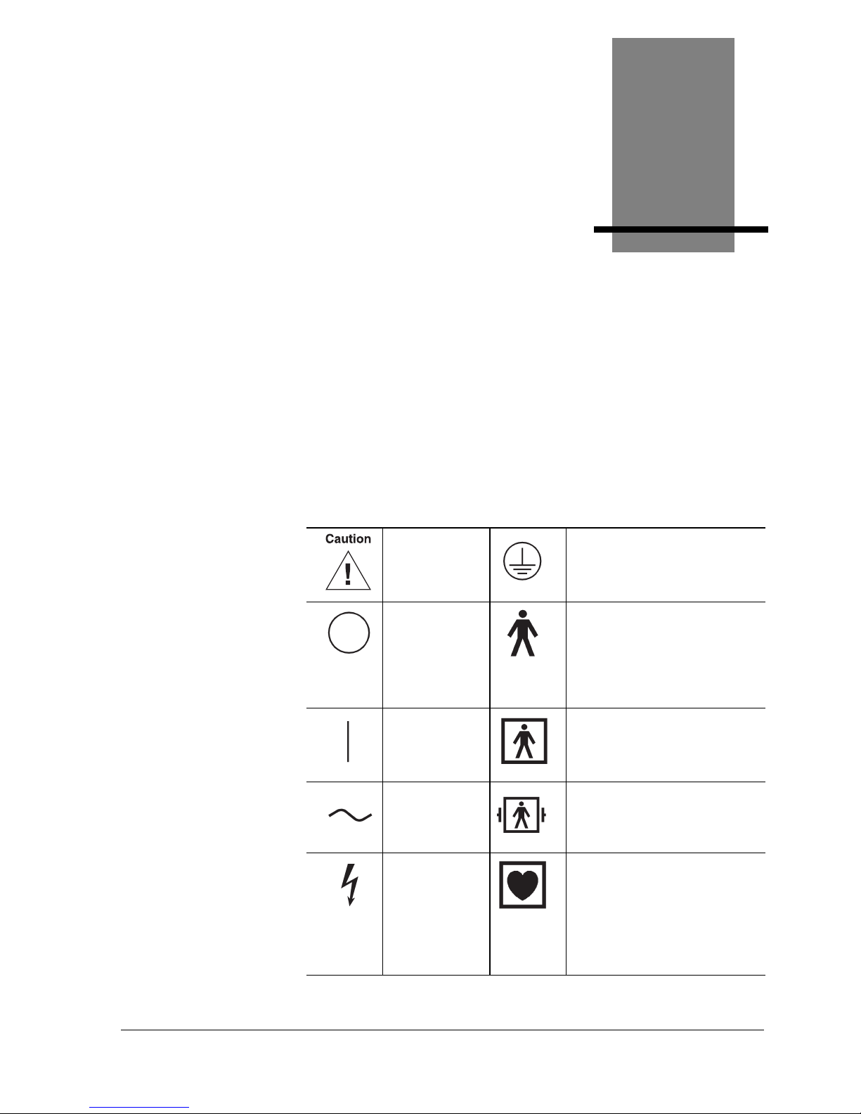
Your treadmill may display one or more of the following
symbols and warning labels for your protection. No single
product displays all.
Attention:
Consult
accompanying
documents
Earth ground (protective)
Off (power
disconnected
from mains)
Type B equipment - provides
adequate protection against
electric shock, particularly
regarding allowable leakage
current; reliability of the protective
earth connection (when present)
On (power
connected to
mains)
Type BF equipment - contains an
F-type isolated patient applied
part providing a high degree of
protection against electric shock
Alternating
current
Type BF equipment with
defibrillation protection
High voltage Type CF equipment - contains an
F-type isolated patient applied
part and provides a degree of
protection against electric shock
higher than that for type BF
equipment regarding allowable
leakage currents
Page 44
E-2 Symbol Definitions Cardiac Stress Treadmills User Guide
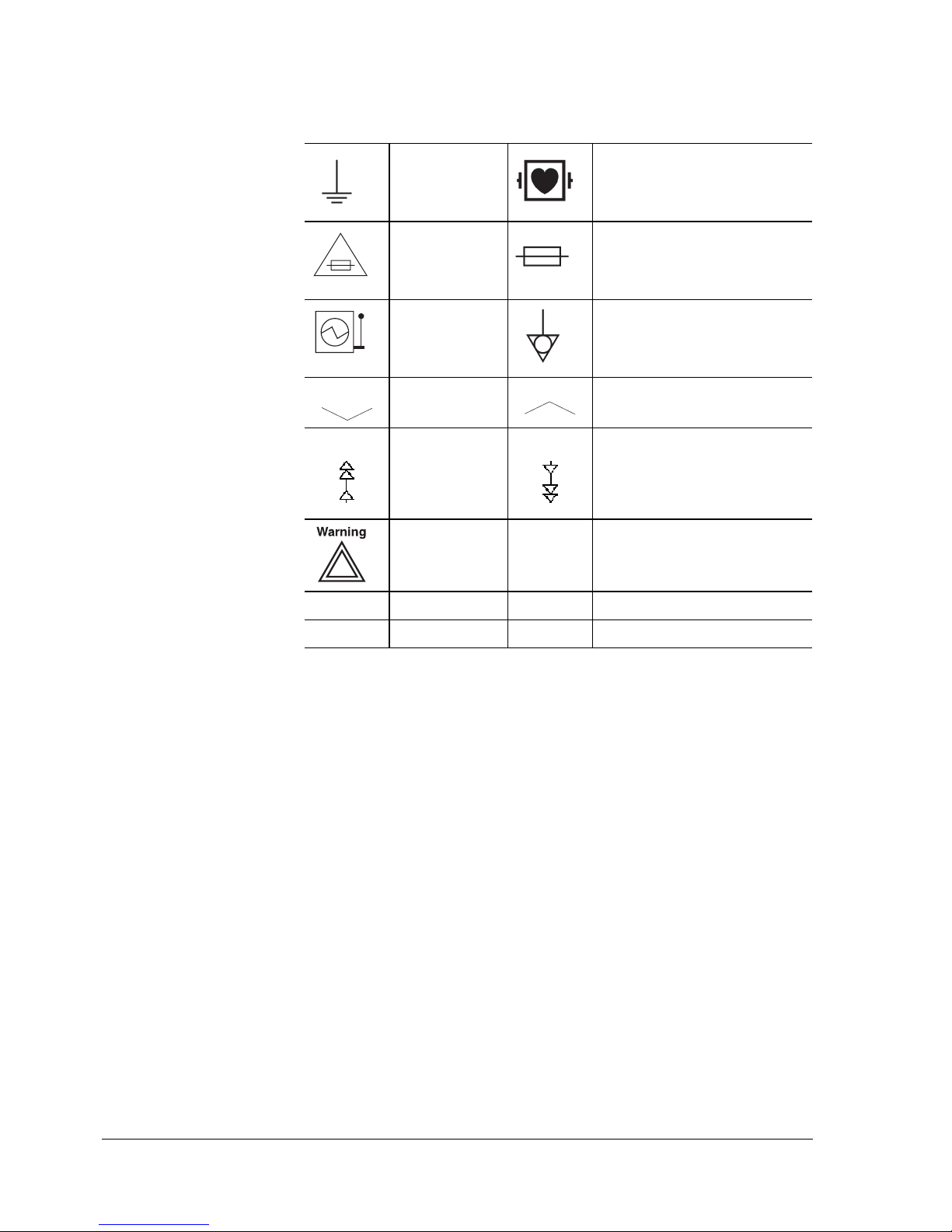
Earth ground
(functional)
Type CF equipment with
defibrillation protection
Replace fuse
only as marked
Fuse
Mains power Equipotentiality
Down Up
Faster Slower
Warning T Timed fuse (slo-blo)
Hz Hertz V Volts
A Amperes VA Volt Amperes
Page 45
Cardiac Stress Treadmills User Guide Index-1
Index
A
Accessories 1-4
Adjustment 3-3
belt tension 3-3
roller guards 3-5
B
Belt tension 3-3
C
Circuit breaker 1-2
trips 3-8
Cleaning 3-2
Commands 1-3
Configuration plate 1-3
Connecting the monitoring
system
C-4
D
Daily inspection 3-1
Deck D-1
Dedicated line 3-8, A-2, C-2
Disinfection 3-2
E
Electrical testing 3-6
Emergency stop button 1-3,
2-3
Ending exercise 2-3
Error codes 3-7
Exercise
ending
2-3
starting 2-2
G
Glossary D-1
Grade D-1
Guidelines
safe operation
2-1
H
Hand grip 1-4
Handrail kit 1-4
Heat dissipation C-2
Hood configuration plate 1-
3
I
Indicators 1-4
Inspection daily 3-1
Installation C-1
site requirements C-2
Instructing the patient 2-2
Introduction 1-1
Page 46

Index--2 Cardiac Stress Treadmills User Guide
M
Maintenance 3-1
Monitoring system D-1
connecting C-4
Moving the treadmill 3-6
O
Operating the treadmill 2-1
Operation 1-3
Options 1-4
Overtightening 3-4
P
Patient
data
1-3, 1-4
instructions 2-2, 2-3, A-3
patient 2-3
Power 1-2
Protocol D-1
R
Receiving C-1
Roller guard D-1
adjustment 3-5
S
Safety requirements A-1
Site requirements C-2
Specifications B-1
Starting the exercise 2-2
Storing the treadmill 3-6
Stress test D-1
Symbols E-1
T
Testing
controller
C-6
treadmill C-5
Tools C-3
Track D-1
Troubleshooting 3-1, 3-7
V
Visual
indicators
1-4
inspection 3-1
W
Walking belt D-1
hesitates 3-8
slips 3-8
 Loading...